US668992A - Bellows for rocking-chairs. - Google Patents
Bellows for rocking-chairs. Download PDFInfo
- Publication number
- US668992A US668992A US68433298A US1898684332A US668992A US 668992 A US668992 A US 668992A US 68433298 A US68433298 A US 68433298A US 1898684332 A US1898684332 A US 1898684332A US 668992 A US668992 A US 668992A
- Authority
- US
- United States
- Prior art keywords
- bellows
- valve
- box
- air
- chair
- Prior art date
- Legal status (The legal status is an assumption and is not a legal conclusion. Google has not performed a legal analysis and makes no representation as to the accuracy of the status listed.)
- Expired - Lifetime
Links
- 238000010276 construction Methods 0.000 description 4
- 239000000126 substance Substances 0.000 description 4
- 239000000659 freezing mixture Substances 0.000 description 2
- 239000002184 metal Substances 0.000 description 2
- 238000012856 packing Methods 0.000 description 2
- 101100001674 Emericella variicolor andI gene Proteins 0.000 description 1
- 241000238631 Hexapoda Species 0.000 description 1
- 241000699666 Mus <mouse, genus> Species 0.000 description 1
- 241000699670 Mus sp. Species 0.000 description 1
- 238000005266 casting Methods 0.000 description 1
- 229940079593 drug Drugs 0.000 description 1
- 239000003814 drug Substances 0.000 description 1
- 239000000463 material Substances 0.000 description 1
- 238000012986 modification Methods 0.000 description 1
- 230000004048 modification Effects 0.000 description 1
- 238000005192 partition Methods 0.000 description 1
- 238000009877 rendering Methods 0.000 description 1
Images


Classifications
-
- A—HUMAN NECESSITIES
- A47—FURNITURE; DOMESTIC ARTICLES OR APPLIANCES; COFFEE MILLS; SPICE MILLS; SUCTION CLEANERS IN GENERAL
- A47C—CHAIRS; SOFAS; BEDS
- A47C3/00—Chairs characterised by structural features; Chairs or stools with rotatable or vertically-adjustable seats
- A47C3/02—Rocking chairs
- A47C3/025—Rocking chairs with seat, or seat and back-rest unit elastically or pivotally mounted in a rigid base frame
- A47C3/027—Rocking chairs with seat, or seat and back-rest unit elastically or pivotally mounted in a rigid base frame with curved rocking members between seat and base frame
Definitions
- My invention is an improvement in the class of rocking-ch airs which are provided with a bellows or other attachment for creating a blast or current of air.
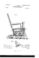
- Figure 1 is a perspective view of a rocking-chair provided with myinvention; Fig. 2, a longitudinal vertical section through the same; Fig. 2, a detail view of the guide-plates Fig. 3, a vertical longitudinal section showing a double bellows; 3, a detail enlarged section of box 40; 4, a detail section of the tubes for conveying the air to the occupant of the chair Fig. 5, a detail section showinga modification of the tubes; Fig. 6, a detail section showing the valve for the box-chambers 40; Fig. 7, a detail plan view of the wire rods for the bellows, and Fig. 8 a detail transverse section through the box 40.
- the numeral 1 represents the chair, which may be of the usual or any desired form or style of rockingchair adapted for the attachment thereto of my invention.
- the rockers 2 of the chair rest on the strips or plates 3, which are preferably covered with carpet or similar covering to render the movement of the rockers thereon noiseless, and said plates or strips are connected by cross-pieces 4 and may be mounted on rollers or casters, if desired.
- a guide-plate 5 is secured to the crosspieces 4 of the plates or strips 3 in a rearwardly-inclined position, and in it is formed a slot 6, having a straight rear wall and a front wall formed with a V-shaped recess, as at 7, into which slots the grooved rollers 8, mounted on studs from the rockers of the chair, work in order to limit the forward and backward creeping movement of the chair while rocking, the V-shaped recesses of the slots receiving the rollers in the forward motion of the chair to prevent the same tilting too far forward.
- the bottom of the casting forming the guide-plate 5 is enlarged and inclines outwardly, so as to prevent the rocker working too close thereto.
- the bellows, valve-chambers, and chambers for chemicals, ice, &c. wholly beneath the chair.
- the numeral 9 represents the bellows, and 10 a box, to which the upper edges of the bellows are secured in any desired airtight manner.
- the box 10 is provided with an air-tight cover or top 11, the side edges of which project beyond the sides of the box to receive the screws for securing the bellows to the chair-seat.
- a valve-ohamber 12 is formed, which has communication through openings 13 in its rear wall with the bellows, said openings being provided with a flap-valve 14, opening in Ward.
- the rear wall of chamber 12 is preferably inclined, as shown in Fig. 2, in order to better direct the air from the bellows to the opening in said rear wall and to insure the proper working of the flap-valve 145.
- an opening 15 (see Fig. 4) is formed, around which are secured the flange-plates 16, into which are secured the ends of the short tubes 17, over which are fitted the ends of the elbowtubes 18 for conducting the air from the valvechamber 12 to the occupant of the chair, as will be described hereinafter.
- the ends of the elbow-tubes 18 are screw-threaded, and rubber or other washer-rings 19 are held in place thereon by the flanged screw-threaded rings 20 in orderto render the joint air-tight between the tubes 17 and said tube 18.
- a similar ring 21 is provided for the upper ends of the tubes 18 to form an air-tight joint between it and the sliding or adjustable tubes 22, telescoped therein, said last-named tubes 22 being provided with flexible nozzles 23, which are fitted over the ends of and connected to the tubes by means of the threaded rings 24, screwed down thereon.
- two openings 25 are formed to receive the perforated tubes 26 for the chemicals, said openings being closed by screw-caps 27.
- a spring-held safety-valve 28 is arranged to permit of escape of surplus air.
- the lower or bottom edges of the bellows are secured to the top edges of a box 29, which is secured to the cross-pieces 4 of the frame or platform for the chair, and at its rear is provided with a removable box 30, having an inclined rear end formed with openings 31, over which a flapvalve 32 works.
- the box forms a cover for the open rear end of box 29, to which it is secured in any desired manner.
- a perforated metallic partition 33 is arranged in order to prevent the entrance of mice and insects to the bellows through the air-inlet openings 34 of the outer wall of said box.
- the flap-valve 32 may be manually operated when desired, as in the event of the valve working hard, by the handle 35, which is connected to the hinged loops 36 and adapted to engage said valve to raise the same when the.
- box 29 may be placed chemicals to medicate and purify the air drawn therethrough or to heat the same, or, as shown, a metallic box 37, containing ice or a suitable freezing mixture, may be placed within said box 29 to cool the air.
- the bellows above described is adapted for unupholstered chairs and when it is desired .to apply the air to the occupant through the tubes described; but for an upholstered chair I have invented the double bellows, (best shown in Fig. 3,) the rear bellows of which is for the purpose of forcing air through the back and seat of the chair and the front bellows for supplying the tubes 18 with air.
- the double bellows (best shown in Fig. 3,) the rear bellows of which is for the purpose of forcing air through the back and seat of the chair and the front bellows for supplying the tubes 18 with air.
- the front bellows is secured to a top box 40, in which is the valve-chamber 4l, having the openings 42 in its bottom, which communicate with the interior of the said front bellows 43 and are covered by the flap-valve 44, said valve being adapted for manual operation by the rod 45, journaled or hinged to the bottom of the box 40 and being bent, as at46, to project through the openings 42 and engage and lift said valve when desired.
- the front wall 47 of the valve-chamber 41 is removably secured in position and is formed with openings to receive the perforated chemical-tn bes 48, which are provided with screw caps or covers 49.
- Asafety-valve 50 covers an opening 51 in said wall 47.
- the box 52 At the rear is arranged the box 52 to receive the valve-chamber 53, which consists of the side walls 54, the inclined rear Wall 55 having an opening therein provided with a valve 56, and the front wall 57, the latter being reinovably securedto the box 52.
- the valve 56 may be operated by the rod 58 passing through the front and rear walls and turned or bent back through the valve-opening to engage valve 56.
- an opening 59 is formed, and a slidevalve 60 is arranged thereover, which controls the admission of air to the space 61 under the chair-seat and to the space 62 in the rear of the chair-back, as described and shown in my Patent No. 580,284, dated April 6, 1897, whereby the air may be delivered through the openings.in said back and seat.
- the front valve-chamber 4]. is connected to the rear valve-chamber 53 by a pipe or tube 63, controlled by a slide-valve 64, so that the air from both bellows may be directed through the tubes 18 when desired by merely closing the valve 60 and opening valve 64.
- a pipe or tube 63 controlled by a slide-valve 64
- valves 56 and 78 By reversing or arranging valves 56 and 78 on the opposite sides of the openings in valve-chamber 53 and box 77 and opening valve 60 the air may be drawn through the perforated back and seat of the chair when the bellows is operated.
- the front bellows is connected at its lower end to a box 65, having a flapvalve 66 arranged in an opening in the top of said box, said valve being adapted for manual operation by an arm 67, formed in a rod 68, and the valve-opening being provided with a perforated metal plate 69.
- the front wall of a box is formed by the front wall 70 of a drawer 71, formed with an inclined top and with the rear portion partly inclosed, said drawer being for the purpose of receiving a receptacle 72 for ice or a freezing mixture, which rests on cleats 73 and against corner-cleats 74 therein, so as to provide a space under and at the front of said receptacle for the passage of air from the inlet-opening 75 in the rear of the drawer to the valve 66 of the front bellows.
- a suitable packing 76 such as rubber tubing, is secured to the top edges of the drawer to make an air-tight joint between the drawer and the box.
- the lower edge of the rear bellows is attached to a box 77, having an opening in its top protected by a perforated metal plate and communicating with the rear bellows and provided with a flap-valve 78 and a rod '79 for manually operating the same, similar to the valve and rod for the front box 65, said box 77 being adapted to receive a wedge-shaped ice box or drawer 80, having an inlet-opening 81 therein, through which the air is drawn into the rear bellows.
- the inlet-openings 75 and 81 may be provided with threaded caps 82 and 83 in order to connect thereto pipes or tubes from mechanically-operated fans in order to force air through the tubes 18 and to the chair, if found desirable so to do, as in the case of chairs or seats in theaters or other buildings where the air might be drawn from hot or cold air storage rooms. Also there may be connected to the tubes 18 pipes or tubes which lead to a musical instrument in order to furnish air thereto.
- the means hereinbefore described for forming an air-tight joint between the tubes 18 and 22 may be modified, as shown in Fig. 5, in which view the tube 22 is formed with flanges 114, between which cord or other suitable packing 115 is arranged, which serves the purpose of the washers 19 and is a less expensive means forforming the joint.
- the flexible nozzle 23 may be lengthened and attached to a spherical rubber bulb 116, adapted to fit over the rounded or saucer-shaped perforated end of a short tube 117, which fits down onto the tube 22. Medicine may be placed on the saucer-shaped end of tube 117, and thus the air passing therethrough becomes impregnated before delivery to the person occupying the chair.
- a bellows having a lower box adapted to receive an ice-receptacle, a removable valvechamber'provided with a flap-valve, an upper box having a valve-chamber, a flap-valve for said last-named chamber, perforated tubes for holding chemicals arranged in said upper valve-chamber, and tubes connected to said chamber to convey the air therefrom.
Landscapes
- Special Chairs (AREA)
Description
" No. 668,992. Patented Feb. 26, 1901 c. u. KBIEG, Sn. BELLOWS FOB ROCKING CHAIRS.
(Application filed June 24. 1e9s.
4 Sheets-Sheet].
(No llodaL') ym- Memes 1n: beams PETERS an. Puomuwa. wuumo'rou, u. c.
No. 668.992. Patented Feb. 26, mm.
c. u. KRIEG, sn. BELLOWSFOR ROCKING CHAIRS.
(No Modal): I (Application filed June 2i 1898, 4 Sheetssh6et 2.
M mus Pawns coy. Pnomurwa. wunmafon. n. c.
No. 668,992. Patanted Feb. 26, l90l.
C; U. KRIEG, SR. BELLOWS FOBQROCKING CHAIRS.
(Application filed June 24. 1898., (No Model.) 4' Shaets-8heet 3 3 .4, I 7 a I M K 4 woentoz III/III Witncmaea I'll "cams Pzrzns cu. PNOTOLITML. wAsnmomu. 04 c.
Patented Feb. 26, l90l.
1%. 668,992. c. u. KBIEG, Sn.
BELLOWS FOB ROCKING CHAIRS.
(Application filed June 24. 1898.)
. 4 Sheets-Sheet 4.
(No Model.)
W'vtmeawa Tun" noams fins: 00.. moromw. wksumawm b. c. I
l ATENT OFFICE.
CHRISTIAN U. KRIEG, SR., OF NASHVILLE, TENNESSEE.
BELLOWS FOR ROCKING-CHAIRS.
SPEGIFIGATION formingpart of Letters Patent No. 668,992, dated February 26, 1901.
Application filed June 24, 1898. Serial No. 684N382. (No model.)
To all whom it 777/6111] concern:
Be it known that I, CHRISTIAN U. KRIEG,SI., a citizen of the United States, residing at Nashville, in the county of Davidson and State of Tennessee,have invented certain new and useful Improvements in Bellows for Rocking-Chairs; andI do declare the following to be a full, ciear, and exact description of the invention, such as will enable others skilled in the art to which it appertains to make and use the same.
My invention is an improvement in the class of rocking-ch airs which are provided with a bellows or other attachment for creating a blast or current of air.
My invention is embodied in the construction, arrangement, and combination of parts, as hereinafter described and claimed, and shown in the accompanying drawings.
In the accompanying drawings, forming a part of this specification, Figure 1 is a perspective view of a rocking-chair provided with myinvention; Fig. 2, a longitudinal vertical section through the same; Fig. 2, a detail view of the guide-plates Fig. 3, a vertical longitudinal section showing a double bellows; 3, a detail enlarged section of box 40; 4, a detail section of the tubes for conveying the air to the occupant of the chair Fig. 5, a detail section showinga modification of the tubes; Fig. 6, a detail section showing the valve for the box-chambers 40; Fig. 7, a detail plan view of the wire rods for the bellows, and Fig. 8 a detail transverse section through the box 40.
Similar numerals refer to similar parts throughout all the views.
Referring to the drawings, the numeral 1 represents the chair, which may be of the usual or any desired form or style of rockingchair adapted for the attachment thereto of my invention. The rockers 2 of the chair rest on the strips or plates 3, which are preferably covered with carpet or similar covering to render the movement of the rockers thereon noiseless, and said plates or strips are connected by cross-pieces 4 and may be mounted on rollers or casters, if desired. At each side of the chair a guide-plate 5 is secured to the crosspieces 4 of the plates or strips 3 in a rearwardly-inclined position, and in it is formed a slot 6, having a straight rear wall and a front wall formed with a V-shaped recess, as at 7, into which slots the grooved rollers 8, mounted on studs from the rockers of the chair, work in order to limit the forward and backward creeping movement of the chair while rocking, the V-shaped recesses of the slots receiving the rollers in the forward motion of the chair to prevent the same tilting too far forward. The bottom of the casting forming the guide-plate 5 is enlarged and inclines outwardly, so as to prevent the rocker working too close thereto. Between the seat of the chair and the frame formed by the strips 3 and oross-pieces4 are arranged the bellows, valve-chambers, and chambers for chemicals, ice, &c., wholly beneath the chair.
Referring more particularly to Fig. 2 of the drawings, the numeral 9 represents the bellows, and 10 a box, to which the upper edges of the bellows are secured in any desired airtight manner. The box 10 is provided with an air-tight cover or top 11, the side edges of which project beyond the sides of the box to receive the screws for securing the bellows to the chair-seat. At the front of the box a valve-ohamber 12 is formed, which has communication through openings 13 in its rear wall with the bellows, said openings being provided with a flap-valve 14, opening in Ward. The rear wall of chamber 12 is preferably inclined, as shown in Fig. 2, in order to better direct the air from the bellows to the opening in said rear wall and to insure the proper working of the flap-valve 145.
In each end of the valve-chamber 12 an opening 15 (see Fig. 4) is formed, around which are secured the flange-plates 16, into which are secured the ends of the short tubes 17, over which are fitted the ends of the elbowtubes 18 for conducting the air from the valvechamber 12 to the occupant of the chair, as will be described hereinafter. The ends of the elbow-tubes 18 are screw-threaded, and rubber or other washer-rings 19 are held in place thereon by the flanged screw-threaded rings 20 in orderto render the joint air-tight between the tubes 17 and said tube 18. A similar ring 21 is provided for the upper ends of the tubes 18 to form an air-tight joint between it and the sliding or adjustable tubes 22, telescoped therein, said last-named tubes 22 being provided with flexible nozzles 23, which are fitted over the ends of and connected to the tubes by means of the threaded rings 24, screwed down thereon.
In the front wall of the valve-chamber 12 two openings 25 are formed to receive the perforated tubes 26 for the chemicals, said openings being closed by screw-caps 27.
In the rear. wall of box l0 a spring-held safety-valve 28 is arranged to permit of escape of surplus air. The lower or bottom edges of the bellows are secured to the top edges of a box 29, which is secured to the cross-pieces 4 of the frame or platform for the chair, and at its rear is provided with a removable box 30, having an inclined rear end formed with openings 31, over which a flapvalve 32 works. The box forms a cover for the open rear end of box 29, to which it is secured in any desired manner. Within the box 30 a perforated metallic partition 33 is arranged in order to prevent the entrance of mice and insects to the bellows through the air-inlet openings 34 of the outer wall of said box.
The flap-valve 32 may be manually operated when desired, as in the event of the valve working hard, by the handle 35, which is connected to the hinged loops 36 and adapted to engage said valve to raise the same when the.
handle is pushed in.
Within the box 29 may be placed chemicals to medicate and purify the air drawn therethrough or to heat the same, or, as shown, a metallic box 37, containing ice or a suitable freezing mixture, may be placed within said box 29 to cool the air.
The back-and-forward motion of the chair while being rocked causes the top of the bellows to lap over the bottom, thus rendering a bellows of the ordinary construction having stiffened sides useless for my purpose, and I have therefore invented a bellows of peculiar construction to meet the requirements and permit of the chair being easily and readily rocked without liability of breaking the sides of the bellows. To accomplish this, I make the bellows with flexible sides and provide wire rods 38, having their ends inturned to prevent cutting the corners of the bellows, which I arrange in the front, rear, and side folds of the bellows, thus holding said folds in their proper position, while the front and rear folds of the bellows are provided with any suitable stiffening material 39. The arrangement and construction of the bellows enable the same to work easily and satisfactorily under the conditions which it must opcrate and also permit of the free movement of the chair.
The bellows above described is adapted for unupholstered chairs and when it is desired .to apply the air to the occupant through the tubes described; but for an upholstered chair I have invented the double bellows, (best shown in Fig. 3,) the rear bellows of which is for the purpose of forcing air through the back and seat of the chair and the front bellows for supplying the tubes 18 with air. Referring to Fig. 3, the front bellows is secured to a top box 40, in which is the valve-chamber 4l, having the openings 42 in its bottom, which communicate with the interior of the said front bellows 43 and are covered by the flap-valve 44, said valve being adapted for manual operation by the rod 45, journaled or hinged to the bottom of the box 40 and being bent, as at46, to project through the openings 42 and engage and lift said valve when desired. The front wall 47 of the valve-chamber 41 is removably secured in position and is formed with openings to receive the perforated chemical-tn bes 48, which are provided with screw caps or covers 49. Asafety-valve 50 covers an opening 51 in said wall 47. At the rear is arranged the box 52 to receive the valve-chamber 53, which consists of the side walls 54, the inclined rear Wall 55 having an opening therein provided with a valve 56, and the front wall 57, the latter being reinovably securedto the box 52. The valve 56 may be operated by the rod 58 passing through the front and rear walls and turned or bent back through the valve-opening to engage valve 56. In the top of box 52 an opening 59 is formed, and a slidevalve 60 is arranged thereover, which controls the admission of air to the space 61 under the chair-seat and to the space 62 in the rear of the chair-back, as described and shown in my Patent No. 580,284, dated April 6, 1897, whereby the air may be delivered through the openings.in said back and seat.
The front valve-chamber 4]. is connected to the rear valve-chamber 53 by a pipe or tube 63, controlled by a slide-valve 64, so that the air from both bellows may be directed through the tubes 18 when desired by merely closing the valve 60 and opening valve 64. By reversing or arranging valves 56 and 78 on the opposite sides of the openings in valve-chamber 53 and box 77 and opening valve 60 the air may be drawn through the perforated back and seat of the chair when the bellows is operated. The front bellows is connected at its lower end to a box 65, having a flapvalve 66 arranged in an opening in the top of said box, said valve being adapted for manual operation by an arm 67, formed in a rod 68, and the valve-opening being provided with a perforated metal plate 69. The front wall of a box is formed by the front wall 70 of a drawer 71, formed with an inclined top and with the rear portion partly inclosed, said drawer being for the purpose of receiving a receptacle 72 for ice or a freezing mixture, which rests on cleats 73 and against corner-cleats 74 therein, so as to provide a space under and at the front of said receptacle for the passage of air from the inlet-opening 75 in the rear of the drawer to the valve 66 of the front bellows.
A suitable packing 76, such as rubber tubing, is secured to the top edges of the drawer to make an air-tight joint between the drawer and the box.
The lower edge of the rear bellows is attached to a box 77, having an opening in its top protected bya perforated metal plate and communicating with the rear bellows and provided with a flap-valve 78 and a rod '79 for manually operating the same, similar to the valve and rod for the front box 65, said box 77 being adapted to receive a wedge-shaped ice box or drawer 80, having an inlet-opening 81 therein, through which the air is drawn into the rear bellows. The inlet-openings 75 and 81 may be provided with threaded caps 82 and 83 in order to connect thereto pipes or tubes from mechanically-operated fans in order to force air through the tubes 18 and to the chair, if found desirable so to do, as in the case of chairs or seats in theaters or other buildings where the air might be drawn from hot or cold air storage rooms. Also there may be connected to the tubes 18 pipes or tubes which lead to a musical instrument in order to furnish air thereto.
The means hereinbefore described for forming an air-tight joint between the tubes 18 and 22 may be modified, as shown in Fig. 5, in which view the tube 22 is formed with flanges 114, between which cord or other suitable packing 115 is arranged, which serves the purpose of the washers 19 and is a less expensive means forforming the joint. Also, as shown in Fig. 5, the flexible nozzle 23 may be lengthened and attached to a spherical rubber bulb 116, adapted to fit over the rounded or saucer-shaped perforated end of a short tube 117, which fits down onto the tube 22. Medicine may be placed on the saucer-shaped end of tube 117, and thus the air passing therethrough becomes impregnated before delivery to the person occupying the chair.
Having thus described my invention, what I claim as new, and desire to secure by Letters Patent, is-
1. The combination, with a rocking-chair, of a pair of bellows having each an inlet adapted to be operated by said chair, outlet valve-chambers for said bellows, a pipe or tube connecting said chambers, and a valve for said pipe or tube for controlling the passage of air from one to the other of said outletchambers.
2. A bellows having a lower box adapted to receive an ice-receptacle, a removable valvechamber'provided with a flap-valve, an upper box having a valve-chamber, a flap-valve for said last-named chamber, perforated tubes for holding chemicals arranged in said upper valve-chamber, and tubes connected to said chamber to convey the air therefrom.
In testimony whereof I affix my signature in presence of two witnesses.
CHRISTIAN U. KRIEG, SR.
\Vitnesses:
GEO. 1W1. FLETCHER, WM. SIMPSON.
Priority Applications (1)
| Application Number | Priority Date | Filing Date | Title |
|---|---|---|---|
| US68433298A US668992A (en) | 1898-06-24 | 1898-06-24 | Bellows for rocking-chairs. |
Applications Claiming Priority (1)
| Application Number | Priority Date | Filing Date | Title |
|---|---|---|---|
| US68433298A US668992A (en) | 1898-06-24 | 1898-06-24 | Bellows for rocking-chairs. |
Publications (1)
| Publication Number | Publication Date |
|---|---|
| US668992A true US668992A (en) | 1901-02-26 |
Family
ID=2737547
Family Applications (1)
| Application Number | Title | Priority Date | Filing Date |
|---|---|---|---|
| US68433298A Expired - Lifetime US668992A (en) | 1898-06-24 | 1898-06-24 | Bellows for rocking-chairs. |
Country Status (1)
| Country | Link |
|---|---|
| US (1) | US668992A (en) |
-
1898
- 1898-06-24 US US68433298A patent/US668992A/en not_active Expired - Lifetime
Similar Documents
| Publication | Publication Date | Title |
|---|---|---|
| US2782834A (en) | Air-conditioned furniture article | |
| US7261371B2 (en) | Ventilation system for an upholstery part | |
| US945234A (en) | Pneumatic mattress. | |
| US668992A (en) | Bellows for rocking-chairs. | |
| KR20210064712A (en) | Ventilation chamber and Car seat including the same | |
| US580284A (en) | Bellows attachment for chairs | |
| US10765219B1 (en) | Lounger having a pneumatic lounging system | |
| US181397A (en) | Improvement in earth-closets | |
| US633398A (en) | Combined rocking-chair and bath. | |
| US1750873A (en) | Ventilating system | |
| US2257555A (en) | Suction cleaner | |
| US134733A (en) | Improvement in foot-rests for chairs | |
| US337521A (en) | scaeeitt | |
| US484072A (en) | Pneumatic chair | |
| US1038394A (en) | Portable vapor-bath cabinet. | |
| US226119A (en) | John n | |
| US192203A (en) | Improvement in seats and backs for chairs | |
| JP4630714B2 (en) | Chair type massage machine | |
| US5365A (en) | Said gould | |
| US95848A (en) | Improved bed and cushion-spring | |
| US1141571A (en) | Compression-pump. | |
| US194389A (en) | Improvement in chairs | |
| US115787A (en) | Improvement in chairs | |
| US229944A (en) | Car-seat | |
| US728141A (en) | Knockdown adjustable chair. |