US6681675B2 - Remote hazardous devices interdiction process and apparatus - Google Patents
Remote hazardous devices interdiction process and apparatus Download PDFInfo
- Publication number
- US6681675B2 US6681675B2 US10/022,215 US2221501A US6681675B2 US 6681675 B2 US6681675 B2 US 6681675B2 US 2221501 A US2221501 A US 2221501A US 6681675 B2 US6681675 B2 US 6681675B2
- Authority
- US
- United States
- Prior art keywords
- high pressure
- abrasive
- fluid
- hazardous
- cutting
- Prior art date
- Legal status (The legal status is an assumption and is not a legal conclusion. Google has not performed a legal analysis and makes no representation as to the accuracy of the status listed.)
- Expired - Lifetime
Links
- 231100001261 hazardous Toxicity 0.000 title claims abstract description 55
- 238000000034 method Methods 0.000 title claims abstract description 50
- 230000008569 process Effects 0.000 title description 2
- 239000012530 fluid Substances 0.000 claims abstract description 72
- 230000000977 initiatory effect Effects 0.000 claims abstract description 14
- 239000002245 particle Substances 0.000 claims abstract description 13
- 238000011065 in-situ storage Methods 0.000 claims abstract description 5
- XLYOFNOQVPJJNP-UHFFFAOYSA-N water Substances O XLYOFNOQVPJJNP-UHFFFAOYSA-N 0.000 claims description 25
- 239000000839 emulsion Substances 0.000 claims description 3
- 238000012546 transfer Methods 0.000 claims description 2
- 239000013056 hazardous product Substances 0.000 claims 11
- 230000001105 regulatory effect Effects 0.000 claims 2
- 239000003082 abrasive agent Substances 0.000 claims 1
- 239000012213 gelatinous substance Substances 0.000 claims 1
- 238000005096 rolling process Methods 0.000 claims 1
- 238000003860 storage Methods 0.000 claims 1
- 239000002360 explosive Substances 0.000 abstract description 9
- 230000008713 feedback mechanism Effects 0.000 abstract description 3
- 239000000463 material Substances 0.000 abstract description 3
- 239000000126 substance Substances 0.000 description 7
- 238000013461 design Methods 0.000 description 5
- 238000005516 engineering process Methods 0.000 description 5
- 238000010586 diagram Methods 0.000 description 3
- 238000012552 review Methods 0.000 description 3
- QGZKDVFQNNGYKY-UHFFFAOYSA-N Ammonia Chemical compound N QGZKDVFQNNGYKY-UHFFFAOYSA-N 0.000 description 2
- 229910003460 diamond Inorganic materials 0.000 description 2
- 239000010432 diamond Substances 0.000 description 2
- 238000011156 evaluation Methods 0.000 description 2
- 239000000499 gel Substances 0.000 description 2
- 239000007788 liquid Substances 0.000 description 2
- 229910021529 ammonia Inorganic materials 0.000 description 1
- 230000009849 deactivation Effects 0.000 description 1
- 230000003203 everyday effect Effects 0.000 description 1
- 238000010304 firing Methods 0.000 description 1
- 230000007246 mechanism Effects 0.000 description 1
- 239000000203 mixture Substances 0.000 description 1
- 238000012986 modification Methods 0.000 description 1
- 230000004048 modification Effects 0.000 description 1
- 230000003287 optical effect Effects 0.000 description 1
- 230000001737 promoting effect Effects 0.000 description 1
- 238000005086 pumping Methods 0.000 description 1
- 238000011160 research Methods 0.000 description 1
- 238000010008 shearing Methods 0.000 description 1
Images


Classifications
-
- F—MECHANICAL ENGINEERING; LIGHTING; HEATING; WEAPONS; BLASTING
- F42—AMMUNITION; BLASTING
- F42B—EXPLOSIVE CHARGES, e.g. FOR BLASTING, FIREWORKS, AMMUNITION
- F42B33/00—Manufacture of ammunition; Dismantling of ammunition; Apparatus therefor
- F42B33/06—Dismantling fuzes, cartridges, projectiles, missiles, rockets or bombs
- F42B33/062—Dismantling fuzes, cartridges, projectiles, missiles, rockets or bombs by high-pressure water jet means
Definitions
- the present invention relates to accessing hazardous devices, and more particularly to a method for the safe and remote access and disruption of packages suspected to contain hazardous devices, chemicals, and/or initiating circuits, using a continuous stream of high pressure liquid, gel, or emulsion.
- the continuous stream is capable of disrupting the initiating system while not presenting sufficient stimuli to initiate explosive, pyrotechnic, or flammable materials.
- U.S. Pat. No. 5,988,038 describes an apparatus and method for destroying buried objects, such as mines. The device shoots a projectile, such as a bullet, into the buried mine essentially destroying the mine on impact.
- U.S. Pat. No. 5,460,154 describes an apparatus for pneumatically propelling a projectile substance. This device is designed like a pneumatic gun and propels a single projectile substance into an explosive device.
- U.S. Pat. No. 5,353,676 describes an apparatus which employs a shearing means, such as a blade, for disassembling a failed explosive device.
- the above mentioned apparatuses can cause the device to explode or are designed to only discharge one projectile at a time resulting in wasted time reloading the apparatus or waiting for the apparatus to recharge. None of the previous devices employ a continuous stream of high velocity abrasive particles and/or fluid(s) for safely deactivating a hazardous device.
- U.S. Pat. No. 6,080,907 describes ammonia fluid jet cutting.
- these fluid jet cutting techniques have been focused on the demilitarization of conventional and chemical military munitions.
- the only known methods for deactivation of hazardous devices such as large vehicle bombs are (1) EOD personnel and (2) explosive disruption techniques.
- the present invention relates to a method for remotely accessing packages containing hazardous devices using a continuous stream of high velocity abrasive particles and/or fluid(s).
- the stream is created in-situ while attached to a remotely or autonomously operated vehicle.
- the object of the invention is accomplished by means of a high pressure fluid being converted to high velocity through an appropriately sized orifice aspirating an abrasive stream from a mixing chamber.
- optimal focusing of the high velocity abrasive particle solution onto the exterior surface of the hazardous device is achieved at a controlled speed and impact area which is below the impact initiation threshold of the hazardous device.
- This invention provides an apparatus design for the safe and remote access of packages suspected to contain hazardous devices, chemicals, and/or initiating systems (fuses, detonators, timers, or triggering devices) using a continuous stream of a high pressure liquid, gel, or emulsion capable of disrupting the initiating systems while not presenting sufficient stimuli to initiate explosive, pyrotechnic, or flammable materials.
- This apparatus is intended to be used on a remotely operated vehicle, but could also be used as a hand-held device or as a personnel operated piece of equipment.
- the process of accessing the hazardous devices can be enhanced by the use of an automatic standoff device such as a commercially available proximity sensor (mechanical, optical, acoustic, etc.) which allows the operator of the remotely operated vehicle or the feedback mechanism of a pre-programmed robotic vehicle to locate the cutting nozzle for the abrasive fluid stream at an optimum standoff distance.
- an automatic standoff device such as a commercially available proximity sensor (mechanical, optical, acoustic, etc.) which allows the operator of the remotely operated vehicle or the feedback mechanism of a pre-programmed robotic vehicle to locate the cutting nozzle for the abrasive fluid stream at an optimum standoff distance.
- the system is an autonomous unit and contains all the components and support equipment necessary to operate the system.
- the system can be deployed to the location of a suspected hazardous device and operated without utility power or any additional support vehicles.
- the system can be deployed with or without a hazardous duty robot.
- a hazardous device In operation a hazardous device can be breached by directing a high-velocity hydroabrasive stream from the fluid jet cutting nozzle onto the exterior of the hazardous device container.
- the device For certain hazardous devices, such as a pipe bomb, the device can be safely disabled using this fluid jet cutting system.
- this fluid jet cutting system can be used to safely access the vehicle interior allowing the EOD squad to more thoroughly assess the hazardous device.
- the cutting nozzle can be mounted on a robot that is capable of directing the hydroabrasive stream to a desired point.
- the cutting nozzle can be mounted on a commercially available programmable x-y stage and deployed to the target by a robot or can be manually-deployed.
- the robot/cutting nozzle is remotely controlled to allow operation at a safe distance.
- the invention provides a remote hazardous device interdiction apparatus which employs a fluid jet cutting nozzle; an abrasive feed system; a high pressure flexible hose; a hose reel; a high pressure intensifier; a power generator supply for electric power; a water reservoir; and an air compressor.
- the instant invention further provides a method for the interdiction of remote hazardous devices which employs the apparatus.
- the pressurization of water is performed using a remote high pressure pump of commercial origin and the pressurized water (50,000 lbs. per sq. in.) is conveyed through a flexible hose or conduit that is stored autonomously with the other equipment contributing to the invention including an intensifier for maintaining the pressurization of water; a water supply reservoir; an air compressor for assisting in the water pressurization; a feedback loop from the intensifier to the water supply reservoir for excess water collection and transfer; and a generator set for providing the necessary power required for operation.
- a small diameter diamond orifice located in a cutting nozzle is used to increase the water flow to one of continuous high velocity and is connected to the flexible hose remotely from the aforementioned equipment.
- the orifice can have a diameter varying from 0.007 inch to 0.014 inch.
- the pressurized water feeds into a hazardous duty robot before exiting at the cutting nozzle.
- This design allows for remote operation in locating and focusing the high velocity water onto a suspect package.
- the cutting nozzle is mounted on an automatic standoff device, an x-y programmable stage, located on the hazardous duty robot. This design allows remote optimal focusing of the high velocity water at a controlled speed and impact area on the exterior of the suspect package.
- FIG. 1 shows a block diagram of an embodiment of the invention
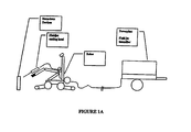
- FIG. 1A shows a schematic view of an embodiment of the invention.
- FIG. 2 shows a block diagram of an embodiment of the invention with a hazardous duty robot
- FIG. 3 shows a block diagram of an embodiment of the invention with a hazardous duty robot and an automatic standoff device.
- FIG. 1 an apparatus 20 for the remote access of packages suspect to contain hazardous devices is shown as an autonomous unit mounted on a skid (not shown).
- a 25 gallon water supply reservoir 22 supplies water to a boost pump 24 .
- the boost pump pressurizes the water to approximately 50 lbs. per sq. inch pumping it to an intensifier 26 .
- the intensifier 26 pressurizes the water to 50,000 lbs./in 2 .
- the air compressor 28 supplies the air that is necessary to operate an emergency stop pressure dump valve (not shown) and the hydroabrasive nozzle ( 40 ).
- a feedback loop 30 collects excess return water from the intensifier 26 and returns it to the water supply reservoir 22 .
- the intensifier 26 forces pressurized water through conduit 32 to a high pressure hose 34 stored on hose reel 36 .
- the high pressure hose terminates in a cutting nozzle 40 which includes a small diameter diamond orifice (not shown).
- the small diameter of the orifice (not shown) included in the cutting nozzle 40 converts the high pressure water to a high velocity continuous stream flow field which can be controlled and directed to an impact area well below the impact initiation threshold of a package suspect of containing a hazardous device.
- Abrasive particles are added to the high pressure water at the orifice (not shown) via an abrasive particle mixing chamber 40 . 1 mounted on the cutting nozzle 40 .
- the abrasive particles enhance the cutting capacity of the high velocity flow field and are an essential component necessary for safely breaching the exterior of the package containing a suspect hazardous device.
- a generator set 42 provides power to the apparatus 20 thus promoting a completely autonomous unit.
- the apparatus 20 can be seen with a hazardous duty robot 44 included in the design.
- the cutting nozzle 40 is mounted on the robot 44 and enhances safety by allowing remote operation of the hydroabrasive cutting nozzle water stream.
- the apparatus 20 is further enhanced with the addition of a programmable x-y stage 46 .
- the programmable x-y stage 46 is an automatic standoff device that allows the operator of the hazardous duty robot 44 to optimally position the continuous stream of water and to more precisely control the cutting speed and impact area.
- the programmable x-y stage 46 is removeably attached to the hazardous duty robot 44 .
- the cutting nozzle 40 is mounted onto the programmable x-y stage 46 . Once programmed, no further human intervention is required until the apparatus 20 has completed its programmed interdiction sequence.
- the programmable x-y stage 46 may be used without the hazardous duty robot 44 with the cutting nozzle 40 directly mounted. It is also feasible to include the programmable x-y stage 46 in a feedback mechanism of an autonomously operated vehicle containing the apparatus 20 .
Landscapes
- Engineering & Computer Science (AREA)
- Manufacturing & Machinery (AREA)
- General Engineering & Computer Science (AREA)
- Perforating, Stamping-Out Or Severing By Means Other Than Cutting (AREA)
Abstract
Description
Claims (54)
Priority Applications (1)
| Application Number | Priority Date | Filing Date | Title |
|---|---|---|---|
| US10/022,215 US6681675B2 (en) | 2000-03-03 | 2001-12-20 | Remote hazardous devices interdiction process and apparatus |
Applications Claiming Priority (3)
| Application Number | Priority Date | Filing Date | Title |
|---|---|---|---|
| US18667300P | 2000-03-03 | 2000-03-03 | |
| US79785201A | 2001-03-05 | 2001-03-05 | |
| US10/022,215 US6681675B2 (en) | 2000-03-03 | 2001-12-20 | Remote hazardous devices interdiction process and apparatus |
Related Parent Applications (1)
| Application Number | Title | Priority Date | Filing Date |
|---|---|---|---|
| US79785201A Continuation-In-Part | 2000-03-03 | 2001-03-05 |
Publications (2)
| Publication Number | Publication Date |
|---|---|
| US20020112598A1 US20020112598A1 (en) | 2002-08-22 |
| US6681675B2 true US6681675B2 (en) | 2004-01-27 |
Family
ID=26882309
Family Applications (1)
| Application Number | Title | Priority Date | Filing Date |
|---|---|---|---|
| US10/022,215 Expired - Lifetime US6681675B2 (en) | 2000-03-03 | 2001-12-20 | Remote hazardous devices interdiction process and apparatus |
Country Status (1)
| Country | Link |
|---|---|
| US (1) | US6681675B2 (en) |
Cited By (10)
| Publication number | Priority date | Publication date | Assignee | Title |
|---|---|---|---|---|
| US20060037462A1 (en) * | 2002-04-12 | 2006-02-23 | Euronord S.A.S. Di G.B Marcolla & C., | Mine removing system |
| US20060178085A1 (en) * | 2005-02-04 | 2006-08-10 | Nicholas Sotereanos | Remotely controlled vehicle |
| US7162943B1 (en) * | 2005-02-14 | 2007-01-16 | The United States Of America As Represented By The Secretary Of The Navy | Cavitating explosively augmented water-jet mine cutter system |
| US20080006142A1 (en) * | 2003-05-23 | 2008-01-10 | Goetsch Duane A | Process for accessing munitions using fluid jet technology |
| US20080083320A1 (en) * | 2006-10-05 | 2008-04-10 | Chang Tony S | System, Method, and Apparatus for Countering Improvised Explosive Devices (IED) |
| US20090223355A1 (en) * | 2006-05-09 | 2009-09-10 | Manders Stephen M | On-site land mine removal system |
| US8240239B1 (en) * | 2011-07-16 | 2012-08-14 | Kevin Mark Diaz | Green energy mine defeat system |
| US20120241016A1 (en) * | 2010-11-22 | 2012-09-27 | Vanair Manufacturing Inc. | Pressurized fluid delivery system and method of use |
| US20130014633A1 (en) * | 2011-07-16 | 2013-01-17 | Kevin Mark Diaz | Green Energy Mine Defeat System |
| RU2772366C1 (en) * | 2021-08-19 | 2022-05-19 | Федеральное казенное предприятие "Казанский государственный казенный пороховой завод" | Portable installation and a method for waterjet cutting of materials containing inflammable and explosive substances |
Families Citing this family (5)
| Publication number | Priority date | Publication date | Assignee | Title |
|---|---|---|---|---|
| US20040132383A1 (en) * | 2002-08-14 | 2004-07-08 | Langford Mark A. | Fluid jet cutting system |
| FI115796B (en) * | 2004-04-14 | 2005-07-15 | Suojasauma Oy | Hollow shield structure for stopping flying bodies e.g. bullets, fragments, shock wave, includes compartments that accommodate absorbent materials which can be mixtures of gel and water |
| WO2021207288A1 (en) * | 2020-04-06 | 2021-10-14 | Delta Subsea Llc | Underwater cut and capture system for submerged munitions |
| CN112562306A (en) * | 2020-11-09 | 2021-03-26 | 天津芯缘君威科技有限公司 | Security check explosive-handling system and explosive-handling method thereof |
| US12460913B2 (en) * | 2023-11-17 | 2025-11-04 | Gradient Technology | Cut-and-capture systems for demilitarization of underwater munitions |
Citations (54)
| Publication number | Priority date | Publication date | Assignee | Title |
|---|---|---|---|---|
| US2340945A (en) | 1942-10-21 | 1944-02-08 | Otto E Ellick | Means for extinguishing incendiary bombs |
| US3594890A (en) | 1968-04-29 | 1971-07-27 | Harold E Cordell | Explosive actuated pulling apparatus |
| US3771413A (en) | 1972-05-01 | 1973-11-13 | Us Army | Mine neutralization device |
| US4046055A (en) | 1975-07-18 | 1977-09-06 | The United States Of America As Represented By The Secretary Of The Army | Apparatus for safely neutralizing explosive devices |
| US4169403A (en) | 1978-08-04 | 1979-10-02 | Hanson Ralph W | Bomb circuit disrupting device and method |
| US4201368A (en) | 1977-11-16 | 1980-05-06 | Manfred Vetter | Arrangement for emergency opening a vehicle door |
| US4437525A (en) * | 1981-07-06 | 1984-03-20 | Flow Industries, Inc. | Hand held water drilling apparatus |
| US4493239A (en) | 1982-04-19 | 1985-01-15 | The United States Of America As Represented By The Secretary Of The Navy | Range clearance by enhancing oxidation of ferrous ordnance in-situ |
| US4589341A (en) | 1984-02-10 | 1986-05-20 | Rockwood Systems Corporation | Method for explosive blast control using expanded foam |
| US4621562A (en) | 1983-05-31 | 1986-11-11 | Monitor Engineers Limited | Remote control robot vehicle |
| US4768709A (en) * | 1986-10-29 | 1988-09-06 | Fluidyne Corporation | Process and apparatus for generating particulate containing fluid jets |
| US4779511A (en) | 1985-07-09 | 1988-10-25 | The United States Of America As Represented By The Secretary Of The Navy | Disposal dearmer for EOD applications |
| US4786848A (en) * | 1987-07-27 | 1988-11-22 | Davidson Textron Inc. | Water jet trim head simulator |
| US4817653A (en) * | 1988-01-22 | 1989-04-04 | Serv-Tech, Inc. | Tank cleaning, water washing robot |
| US4826087A (en) * | 1985-02-12 | 1989-05-02 | David Chinery | Manipulative device |
| US4836079A (en) | 1987-01-14 | 1989-06-06 | Cube Overseas Trading Ltd | Bomb blast inhibitor and method of bomb blast inhibition |
| US4840105A (en) | 1987-03-16 | 1989-06-20 | Israel Aircraft Industries Ltd. | Mine field clearing apparatus |
| US4854982A (en) | 1989-01-31 | 1989-08-08 | The United States Of America As Represented By The Secretary Of The Army | Method to dimilitarize extract, and recover ammonium perchlorate from composite propellants using liquid ammonia |
| US4909152A (en) | 1987-08-08 | 1990-03-20 | Mauser-Werke Oberndorf Gmbh | Cartridge for the expulsion of liquids under pressure |
| US4919034A (en) | 1988-01-28 | 1990-04-24 | Firth Charles B | Mine clearing apparatus |
| US4932831A (en) | 1988-09-26 | 1990-06-12 | Remotec, Inc. | All terrain mobile robot |
| US4955939A (en) | 1983-03-02 | 1990-09-11 | The United States Of America As Represented By The Secretary Of The Navy | Shaped charge with explosively driven liquid follow through |
| US4957027A (en) | 1989-10-02 | 1990-09-18 | The United States Of America As Represented By The Secretary Of The Navy | Versatile nonelectric dearmer |
| US5007325A (en) | 1985-01-10 | 1991-04-16 | Aardvark Clear Mine Limited Of Shevock Farm | Apparatus for clearing mines |
| US5134921A (en) | 1990-06-24 | 1992-08-04 | Custom Engineering And Designs, Inc. | Water cannon for neutralizing explosive devices, and replaceable cartridge therefor |
| US5136920A (en) | 1990-06-24 | 1992-08-11 | Custom Engineering And Design, Inc. | Water cannon for neutralizing explosive devices, and replaceable cartridge therefor |
| US5140891A (en) | 1990-09-21 | 1992-08-25 | Technology International Incorporated | Explosive ordnance disposal and mine neutralization system |
| US5203646A (en) * | 1992-02-06 | 1993-04-20 | Cornell Research Foundation, Inc. | Cable crawling underwater inspection and cleaning robot |
| US5210368A (en) | 1992-04-15 | 1993-05-11 | Heller Jr James M | Bomb neutralizing apparatus |
| US5223661A (en) | 1990-09-21 | 1993-06-29 | Technology International Incorporated | Rapid area clearance of explosives |
| US5223666A (en) | 1992-06-04 | 1993-06-29 | The United States Of America As Represented By The Secretary Of The Navy | Apparatus for clearing mines |
| US5249500A (en) | 1990-09-21 | 1993-10-05 | Technology International Incorporated | Rapid area clearance of explosives |
| US5301594A (en) | 1992-12-30 | 1994-04-12 | Loctite Corporation | Apparatus and method for effecting penetration and mass transfer at a penetrable situs |
| US5353676A (en) | 1993-12-27 | 1994-10-11 | The United States Of America As Represented By The Secretary Of The Army | Apparatus and method for remote disassembly of failed high explosive type mine |
| US5363603A (en) | 1992-06-22 | 1994-11-15 | Alliant Techsystems, Inc. | Abrasive fluid jet cutting compositon and method |
| US5386758A (en) | 1993-09-13 | 1995-02-07 | Conley; Kenneth A. | Apparatus and method for disarming pipe bombs |
| US5430229A (en) | 1992-12-30 | 1995-07-04 | Hercules Incorporated | Chemical process for disposal of rocket propellant containing nitrate ester |
| US5448936A (en) | 1994-08-23 | 1995-09-12 | Hughes Aircraft Company | Destruction of underwater objects |
| US5452639A (en) | 1992-12-16 | 1995-09-26 | Tzn Forschungs- Und Entwicklungszentrum Unterluss Gmbh | Arrangement for locating below-ground ammunition |
| US5460154A (en) | 1993-09-10 | 1995-10-24 | Earth Resources Corporation | Method for pneumatically propelling a projectile substance |
| US5516970A (en) | 1991-08-30 | 1996-05-14 | Global Environmental Solutions, Inc. | Process and apparatus for photolytic degradation of explosives |
| US5527204A (en) * | 1993-08-27 | 1996-06-18 | Rhoades; Lawrence J. | Abrasive jet stream cutting |
| US5574203A (en) | 1993-04-26 | 1996-11-12 | Snpe Ingenierie S.A. | Process and installation for destroying munitions containing toxic agents |
| US5657676A (en) | 1993-11-02 | 1997-08-19 | Fichtel & Sachs Ag | Process and apparatus for the removal of gases and/or liquids from a container |
| US5728967A (en) | 1995-11-08 | 1998-03-17 | Parkes; John H. | Suppressing explosions and installation |
| US5737709A (en) | 1994-12-29 | 1998-04-07 | Getty; Heather L. | High pressure washout of explosives agents |
| US5743246A (en) | 1993-09-10 | 1998-04-28 | Earth Resources Corporation | Cannon for disarming an explosive device |
| US5770913A (en) * | 1995-10-23 | 1998-06-23 | Omnific International, Ltd. | Actuators, motors and wheelless autonomous robots using vibratory transducer drivers |
| US5859372A (en) * | 1994-04-11 | 1999-01-12 | Neltoft; Peter | Device for use in manual control of the movement of a real or imaginary object |
| US5936184A (en) | 1997-11-21 | 1999-08-10 | Tracor Aerospace, Inc. | Devices and methods for clearance of mines or ordnance |
| US5979289A (en) | 1995-08-24 | 1999-11-09 | J R French Limited | Apparatus for and method of detonating mines |
| US5988038A (en) | 1998-01-22 | 1999-11-23 | Raytheon Company | Method and apparatus for destroying buried objects |
| US5987723A (en) | 1997-01-15 | 1999-11-23 | Mcnally; Daniel L. | Apparatus and method for rapid, remote, forcible entry |
| US6080907A (en) | 1998-04-27 | 2000-06-27 | Teledyne Commodore, L.L.C. | Ammonia fluidjet cutting in demilitarization processes using solvated electrons |
-
2001
- 2001-12-20 US US10/022,215 patent/US6681675B2/en not_active Expired - Lifetime
Patent Citations (55)
| Publication number | Priority date | Publication date | Assignee | Title |
|---|---|---|---|---|
| US2340945A (en) | 1942-10-21 | 1944-02-08 | Otto E Ellick | Means for extinguishing incendiary bombs |
| US3594890A (en) | 1968-04-29 | 1971-07-27 | Harold E Cordell | Explosive actuated pulling apparatus |
| US3771413A (en) | 1972-05-01 | 1973-11-13 | Us Army | Mine neutralization device |
| US4046055A (en) | 1975-07-18 | 1977-09-06 | The United States Of America As Represented By The Secretary Of The Army | Apparatus for safely neutralizing explosive devices |
| US4201368A (en) | 1977-11-16 | 1980-05-06 | Manfred Vetter | Arrangement for emergency opening a vehicle door |
| US4169403A (en) | 1978-08-04 | 1979-10-02 | Hanson Ralph W | Bomb circuit disrupting device and method |
| US4437525A (en) * | 1981-07-06 | 1984-03-20 | Flow Industries, Inc. | Hand held water drilling apparatus |
| US4493239A (en) | 1982-04-19 | 1985-01-15 | The United States Of America As Represented By The Secretary Of The Navy | Range clearance by enhancing oxidation of ferrous ordnance in-situ |
| US4955939A (en) | 1983-03-02 | 1990-09-11 | The United States Of America As Represented By The Secretary Of The Navy | Shaped charge with explosively driven liquid follow through |
| US4621562A (en) | 1983-05-31 | 1986-11-11 | Monitor Engineers Limited | Remote control robot vehicle |
| US4589341A (en) | 1984-02-10 | 1986-05-20 | Rockwood Systems Corporation | Method for explosive blast control using expanded foam |
| US5007325A (en) | 1985-01-10 | 1991-04-16 | Aardvark Clear Mine Limited Of Shevock Farm | Apparatus for clearing mines |
| US4826087A (en) * | 1985-02-12 | 1989-05-02 | David Chinery | Manipulative device |
| US4779511A (en) | 1985-07-09 | 1988-10-25 | The United States Of America As Represented By The Secretary Of The Navy | Disposal dearmer for EOD applications |
| US4768709A (en) * | 1986-10-29 | 1988-09-06 | Fluidyne Corporation | Process and apparatus for generating particulate containing fluid jets |
| US4836079A (en) | 1987-01-14 | 1989-06-06 | Cube Overseas Trading Ltd | Bomb blast inhibitor and method of bomb blast inhibition |
| US4840105A (en) | 1987-03-16 | 1989-06-20 | Israel Aircraft Industries Ltd. | Mine field clearing apparatus |
| US4786848A (en) * | 1987-07-27 | 1988-11-22 | Davidson Textron Inc. | Water jet trim head simulator |
| US4909152A (en) | 1987-08-08 | 1990-03-20 | Mauser-Werke Oberndorf Gmbh | Cartridge for the expulsion of liquids under pressure |
| US4817653A (en) * | 1988-01-22 | 1989-04-04 | Serv-Tech, Inc. | Tank cleaning, water washing robot |
| US4919034A (en) | 1988-01-28 | 1990-04-24 | Firth Charles B | Mine clearing apparatus |
| US4932831A (en) | 1988-09-26 | 1990-06-12 | Remotec, Inc. | All terrain mobile robot |
| US4854982A (en) | 1989-01-31 | 1989-08-08 | The United States Of America As Represented By The Secretary Of The Army | Method to dimilitarize extract, and recover ammonium perchlorate from composite propellants using liquid ammonia |
| US4957027A (en) | 1989-10-02 | 1990-09-18 | The United States Of America As Represented By The Secretary Of The Navy | Versatile nonelectric dearmer |
| US5134921A (en) | 1990-06-24 | 1992-08-04 | Custom Engineering And Designs, Inc. | Water cannon for neutralizing explosive devices, and replaceable cartridge therefor |
| US5136920A (en) | 1990-06-24 | 1992-08-11 | Custom Engineering And Design, Inc. | Water cannon for neutralizing explosive devices, and replaceable cartridge therefor |
| US5140891A (en) | 1990-09-21 | 1992-08-25 | Technology International Incorporated | Explosive ordnance disposal and mine neutralization system |
| US5223661A (en) | 1990-09-21 | 1993-06-29 | Technology International Incorporated | Rapid area clearance of explosives |
| US5249500A (en) | 1990-09-21 | 1993-10-05 | Technology International Incorporated | Rapid area clearance of explosives |
| US5516970A (en) | 1991-08-30 | 1996-05-14 | Global Environmental Solutions, Inc. | Process and apparatus for photolytic degradation of explosives |
| US5203646A (en) * | 1992-02-06 | 1993-04-20 | Cornell Research Foundation, Inc. | Cable crawling underwater inspection and cleaning robot |
| US5210368A (en) | 1992-04-15 | 1993-05-11 | Heller Jr James M | Bomb neutralizing apparatus |
| US5223666A (en) | 1992-06-04 | 1993-06-29 | The United States Of America As Represented By The Secretary Of The Navy | Apparatus for clearing mines |
| US5363603A (en) | 1992-06-22 | 1994-11-15 | Alliant Techsystems, Inc. | Abrasive fluid jet cutting compositon and method |
| US5452639A (en) | 1992-12-16 | 1995-09-26 | Tzn Forschungs- Und Entwicklungszentrum Unterluss Gmbh | Arrangement for locating below-ground ammunition |
| US5301594A (en) | 1992-12-30 | 1994-04-12 | Loctite Corporation | Apparatus and method for effecting penetration and mass transfer at a penetrable situs |
| US5430229A (en) | 1992-12-30 | 1995-07-04 | Hercules Incorporated | Chemical process for disposal of rocket propellant containing nitrate ester |
| US5574203A (en) | 1993-04-26 | 1996-11-12 | Snpe Ingenierie S.A. | Process and installation for destroying munitions containing toxic agents |
| US5527204A (en) * | 1993-08-27 | 1996-06-18 | Rhoades; Lawrence J. | Abrasive jet stream cutting |
| US5785038A (en) | 1993-09-10 | 1998-07-28 | Earth Resources Corporation | Cannon for disarming an explosive device |
| US5460154A (en) | 1993-09-10 | 1995-10-24 | Earth Resources Corporation | Method for pneumatically propelling a projectile substance |
| US5743246A (en) | 1993-09-10 | 1998-04-28 | Earth Resources Corporation | Cannon for disarming an explosive device |
| US5386758A (en) | 1993-09-13 | 1995-02-07 | Conley; Kenneth A. | Apparatus and method for disarming pipe bombs |
| US5657676A (en) | 1993-11-02 | 1997-08-19 | Fichtel & Sachs Ag | Process and apparatus for the removal of gases and/or liquids from a container |
| US5353676A (en) | 1993-12-27 | 1994-10-11 | The United States Of America As Represented By The Secretary Of The Army | Apparatus and method for remote disassembly of failed high explosive type mine |
| US5859372A (en) * | 1994-04-11 | 1999-01-12 | Neltoft; Peter | Device for use in manual control of the movement of a real or imaginary object |
| US5448936A (en) | 1994-08-23 | 1995-09-12 | Hughes Aircraft Company | Destruction of underwater objects |
| US5737709A (en) | 1994-12-29 | 1998-04-07 | Getty; Heather L. | High pressure washout of explosives agents |
| US5979289A (en) | 1995-08-24 | 1999-11-09 | J R French Limited | Apparatus for and method of detonating mines |
| US5770913A (en) * | 1995-10-23 | 1998-06-23 | Omnific International, Ltd. | Actuators, motors and wheelless autonomous robots using vibratory transducer drivers |
| US5728967A (en) | 1995-11-08 | 1998-03-17 | Parkes; John H. | Suppressing explosions and installation |
| US5987723A (en) | 1997-01-15 | 1999-11-23 | Mcnally; Daniel L. | Apparatus and method for rapid, remote, forcible entry |
| US5936184A (en) | 1997-11-21 | 1999-08-10 | Tracor Aerospace, Inc. | Devices and methods for clearance of mines or ordnance |
| US5988038A (en) | 1998-01-22 | 1999-11-23 | Raytheon Company | Method and apparatus for destroying buried objects |
| US6080907A (en) | 1998-04-27 | 2000-06-27 | Teledyne Commodore, L.L.C. | Ammonia fluidjet cutting in demilitarization processes using solvated electrons |
Non-Patent Citations (25)
| Title |
|---|
| "Appendix G-Fluid-Jet Cutting of Ordnance and High-Pressure Clean-Out of Energetic Materials", the Nat'l Academy Press, 1999, pp. 235-239; pulled from the internet Jun. 6, 2001, http://books.nap.edu/books.nap.edu/books/0309066395/html. |
| "Applications", pulled from the internet Mar. 10, 2002, http://grpweb.gintic.gov.sg/~wjweb/Applications/Applications page 1.html, 10 pages. |
| "Colt Product Range", various illustrations pulled from the internet Oct. 29, 2002 and Nov. 6, 2002, 30 pages. |
| "Demilitarization Services", ATK Thiokol Propulsion Demilitarization Services, 2002, 1 page, pulled from the internet Nov. 6, 2002, http://www.thiokol.com/demil/htm. various illustrations pulled from the internet Oct. 29, 2002, 22 pages. |
| "DiaJet Osprey", pulled from the internet on Mar. 10, 2002, http://www.phrgroup.comuk/diajet/osprey.htm, 4 pages. |
| "Disposal of Conventional Ordnance", pulled from the internet on Mar. 10, 2002, http://aai.business.israel.net/eod/3.htm, 4 pages. |
| "Manufacturing Engineer on a disk", Version 1.0 Aug. 31, 2001, pulled from the internet Mar. 30, 2002, http://claymore.engineer.gvsu.edu/~jackh/eod/manufact/manufact-272.html. |
| "Mobile Disrupter Vehicle", article found at http://www.inuktun.com, 4 pages. |
| "New Technology Revolutionizes War Material Removal and Bomb Defusing", "Waterjet Use Dealing With the Problem of Anti-Personnel Landmines", D.A. Summers, et al., 10<th >American Waterjet Conference Aug. 14-17, 1999, 10 pages. |
| "Other Detection Technologies Workshop", pulled from the internet Mar. 10, 2002, http://www.uxocoe.brtrc.com/WorkshopNote/otherdetect.htm, 17 pages. |
| "Petroleum Place: Oil & Gas Business Directory: Abrasive Cutting", pulled from the internet Mar. 10, 2002, http://www.petroleumplace.com/BusinessDirectory/AbrasiveCutting/. |
| "Site Map for WJTC (Under Construction)", pulled from the internet on Mar. 10, 2002, http://grpweb.gintic.gov.sg/~wjweb/Site%20Map/Site%20page%201.html, 3 pages. |
| "The Website for Defense Industries-Army", pulled from the internet Oct. 29, 2002, http://www.army-technology.com/contractors/mines/remotec/. |
| "WaterJetCutting Abrasive Cutting WaterJet Jet Cutting Water Cutting ANT AG", Applied New Technologies AG, pulled from the internet on Mar. 10, 2002, http://WWW.ant-ag.net/en/set_home.html, 2 pages. |
| "WWW Links (Humanitarian Demining)-ExtendedRef", pulled from the internet on Mar. 11, 2002, http://Diwww.epfl.ch/lami/detec/minelinks.html, 17 pages. |
| "Appendix G—Fluid-Jet Cutting of Ordnance and High-Pressure Clean-Out of Energetic Materials", the Nat'l Academy Press, 1999, pp. 235-239; pulled from the internet Jun. 6, 2001, http://books.nap.edu/books.nap.edu/books/0309066395/html. |
| "Applications", pulled from the internet Mar. 10, 2002, http://grpweb.gintic.gov.sg/˜wjweb/Applications/Applications page 1.html, 10 pages. |
| "Manufacturing Engineer on a disk", Version 1.0 Aug. 31, 2001, pulled from the internet Mar. 30, 2002, http://claymore.engineer.gvsu.edu/˜jackh/eod/manufact/manufact-272.html. |
| "New Technology Revolutionizes War Material Removal and Bomb Defusing", "Waterjet Use Dealing With the Problem of Anti-Personnel Landmines", D.A. Summers, et al., 10th American Waterjet Conference Aug. 14-17, 1999, 10 pages. |
| "Site Map for WJTC (Under Construction)", pulled from the internet on Mar. 10, 2002, http://grpweb.gintic.gov.sg/˜wjweb/Site%20Map/Site%20page%201.html, 3 pages. |
| "The Website for Defense Industries—Army", pulled from the internet Oct. 29, 2002, http://www.army-technology.com/contractors/mines/remotec/. |
| "WWW Links (Humanitarian Demining)—ExtendedRef", pulled from the internet on Mar. 11, 2002, http://Diwww.epfl.ch/lami/detec/minelinks.html, 17 pages. |
| Hugh Jack, Manufacturing Engineer on a disk, Apr. 20, 1998, Hugh Jack, pp. 6-9.* * |
| Jetedge.com, Hydro-Crawler, Dec. 22, 1999, Jet Edge.* * |
| Jetedge.com, Jet Edge, Jan. 31, 1997, Jet Edge.* * |
Cited By (18)
| Publication number | Priority date | Publication date | Assignee | Title |
|---|---|---|---|---|
| US20060037462A1 (en) * | 2002-04-12 | 2006-02-23 | Euronord S.A.S. Di G.B Marcolla & C., | Mine removing system |
| US20080006142A1 (en) * | 2003-05-23 | 2008-01-10 | Goetsch Duane A | Process for accessing munitions using fluid jet technology |
| US7328643B2 (en) * | 2003-05-23 | 2008-02-12 | Gradient Technology | Process for accessing munitions using fluid jet technology |
| US8083569B2 (en) * | 2005-02-04 | 2011-12-27 | Nicholas Sotereanos | Remotely controlled vehicle |
| US20060178085A1 (en) * | 2005-02-04 | 2006-08-10 | Nicholas Sotereanos | Remotely controlled vehicle |
| US7162943B1 (en) * | 2005-02-14 | 2007-01-16 | The United States Of America As Represented By The Secretary Of The Navy | Cavitating explosively augmented water-jet mine cutter system |
| US20090223355A1 (en) * | 2006-05-09 | 2009-09-10 | Manders Stephen M | On-site land mine removal system |
| US7600460B2 (en) * | 2006-05-09 | 2009-10-13 | Stephen M. Manders | On-site land mine removal system |
| US20080083320A1 (en) * | 2006-10-05 | 2008-04-10 | Chang Tony S | System, Method, and Apparatus for Countering Improvised Explosive Devices (IED) |
| US20120241016A1 (en) * | 2010-11-22 | 2012-09-27 | Vanair Manufacturing Inc. | Pressurized fluid delivery system and method of use |
| US8567299B2 (en) * | 2010-11-22 | 2013-10-29 | Vanair Manufacturing, Inc. | Pressurized fluid delivery system and method of use |
| US8770082B1 (en) * | 2010-11-22 | 2014-07-08 | Vanair Manufacturing, Inc. | Pressurized fluid delivery system and method of use |
| US8240239B1 (en) * | 2011-07-16 | 2012-08-14 | Kevin Mark Diaz | Green energy mine defeat system |
| US20130014633A1 (en) * | 2011-07-16 | 2013-01-17 | Kevin Mark Diaz | Green Energy Mine Defeat System |
| US20140007756A1 (en) * | 2011-07-16 | 2014-01-09 | Kevin Mark Diaz | Green Energy Mine Defeat System |
| US8677876B2 (en) * | 2011-07-16 | 2014-03-25 | Kevin Mark Diaz | 4D simultaneous robotic containment with recoil |
| US9234725B2 (en) * | 2011-07-16 | 2016-01-12 | Kevin Mark Diaz | Green energy mine defeat system |
| RU2772366C1 (en) * | 2021-08-19 | 2022-05-19 | Федеральное казенное предприятие "Казанский государственный казенный пороховой завод" | Portable installation and a method for waterjet cutting of materials containing inflammable and explosive substances |
Also Published As
| Publication number | Publication date |
|---|---|
| US20020112598A1 (en) | 2002-08-22 |
Similar Documents
| Publication | Publication Date | Title |
|---|---|---|
| US6681675B2 (en) | Remote hazardous devices interdiction process and apparatus | |
| US12173990B2 (en) | Electrode for a conducted electrical weapon | |
| US7478680B2 (en) | Fire extinguishing by explosive pulverisation of projectile based frozen gases and compacted solid extinguishing agents | |
| US11274900B2 (en) | Method and apparatus for rendering safe unexploded ordnance | |
| US8371903B2 (en) | Portable demilitarization apparatus for segmenting ordnance | |
| US5301594A (en) | Apparatus and method for effecting penetration and mass transfer at a penetrable situs | |
| US7275529B2 (en) | Incendiary projectile launcher | |
| US20160339280A1 (en) | Fire Extinguishing Pod | |
| US5657676A (en) | Process and apparatus for the removal of gases and/or liquids from a container | |
| US7182011B2 (en) | Mine retrieval method and apparatus | |
| US11320247B2 (en) | Stand-off breaching round | |
| US3713383A (en) | Dispersal technique for cw bw agents | |
| US20020050534A1 (en) | Textile and cordage net fire extinguisher system | |
| CA2880114A1 (en) | Hyper-pressure pulse excavator | |
| US4678010A (en) | Accumulator for airless spraying apparatus | |
| WO2004005838A1 (en) | Device for disarming explosive | |
| US7828078B2 (en) | System for rapidly boring through materials | |
| US20170146325A1 (en) | Line charge | |
| WO2002077563A1 (en) | A method and apparatus for neutralising an explosive device | |
| KR20020060747A (en) | Driver for power tools | |
| JP2024125764A (en) | Drilling and loading system and method | |
| Bernard | Robotic Manufacture of Hazardous Substances | |
| DE10353571A1 (en) | Arrangement for fire limitation and extinguishing, using containers with integrated detonators | |
| WO2013187793A1 (en) | Pneumatic-pulse throwing method and device for carrying out same |
Legal Events
| Date | Code | Title | Description |
|---|---|---|---|
| AS | Assignment |
Owner name: TELEDYNE BROWN ENGINEERING, INC., ALABAMA Free format text: ASSIGNMENT OF ASSIGNORS INTEREST;ASSIGNOR:MILLER, PAUL L.;REEL/FRAME:012901/0396 Effective date: 20020311 |
|
| FEPP | Fee payment procedure |
Free format text: PAYOR NUMBER ASSIGNED (ORIGINAL EVENT CODE: ASPN); ENTITY STATUS OF PATENT OWNER: LARGE ENTITY |
|
| STCF | Information on status: patent grant |
Free format text: PATENTED CASE |
|
| FPAY | Fee payment |
Year of fee payment: 4 |
|
| FPAY | Fee payment |
Year of fee payment: 8 |
|
| FEPP | Fee payment procedure |
Free format text: PAYER NUMBER DE-ASSIGNED (ORIGINAL EVENT CODE: RMPN); ENTITY STATUS OF PATENT OWNER: LARGE ENTITY Free format text: PAYOR NUMBER ASSIGNED (ORIGINAL EVENT CODE: ASPN); ENTITY STATUS OF PATENT OWNER: LARGE ENTITY |
|
| FPAY | Fee payment |
Year of fee payment: 12 |