US5134921A - Water cannon for neutralizing explosive devices, and replaceable cartridge therefor - Google Patents
Water cannon for neutralizing explosive devices, and replaceable cartridge therefor Download PDFInfo
- Publication number
- US5134921A US5134921A US07/762,654 US76265491A US5134921A US 5134921 A US5134921 A US 5134921A US 76265491 A US76265491 A US 76265491A US 5134921 A US5134921 A US 5134921A
- Authority
- US
- United States
- Prior art keywords
- cannon
- assembly
- upright
- platform
- liquid
- Prior art date
- Legal status (The legal status is an assumption and is not a legal conclusion. Google has not performed a legal analysis and makes no representation as to the accuracy of the status listed.)
- Expired - Fee Related
Links
Images


Classifications
-
- F—MECHANICAL ENGINEERING; LIGHTING; HEATING; WEAPONS; BLASTING
- F41—WEAPONS
- F41B—WEAPONS FOR PROJECTING MISSILES WITHOUT USE OF EXPLOSIVE OR COMBUSTIBLE PROPELLANT CHARGE; WEAPONS NOT OTHERWISE PROVIDED FOR
- F41B9/00—Liquid ejecting guns, e.g. water pistols, devices ejecting electrically charged liquid jets, devices ejecting liquid jets by explosive pressure
- F41B9/0003—Liquid ejecting guns, e.g. water pistols, devices ejecting electrically charged liquid jets, devices ejecting liquid jets by explosive pressure characterised by the pressurisation of the liquid
- F41B9/0031—Liquid ejecting guns, e.g. water pistols, devices ejecting electrically charged liquid jets, devices ejecting liquid jets by explosive pressure characterised by the pressurisation of the liquid the liquid being pressurised at the moment of ejection
- F41B9/0043—Pressurisation by explosive pressure
- F41B9/0046—Disruptors, i.e. for neutralising explosive devices
-
- F—MECHANICAL ENGINEERING; LIGHTING; HEATING; WEAPONS; BLASTING
- F41—WEAPONS
- F41A—FUNCTIONAL FEATURES OR DETAILS COMMON TO BOTH SMALLARMS AND ORDNANCE, e.g. CANNONS; MOUNTINGS FOR SMALLARMS OR ORDNANCE
- F41A23/00—Gun mountings, e.g. on vehicles; Disposition of guns on vehicles
- F41A23/02—Mountings without wheels
- F41A23/04—Unipods
- F41A23/06—Unipods adjustable
-
- F—MECHANICAL ENGINEERING; LIGHTING; HEATING; WEAPONS; BLASTING
- F42—AMMUNITION; BLASTING
- F42B—EXPLOSIVE CHARGES, e.g. FOR BLASTING, FIREWORKS, AMMUNITION
- F42B33/00—Manufacture of ammunition; Dismantling of ammunition; Apparatus therefor
- F42B33/06—Dismantling fuzes, cartridges, projectiles, missiles, rockets or bombs
- F42B33/062—Dismantling fuzes, cartridges, projectiles, missiles, rockets or bombs by high-pressure water jet means
Landscapes
- Engineering & Computer Science (AREA)
- General Engineering & Computer Science (AREA)
- Manufacturing & Machinery (AREA)
- Catching Or Destruction (AREA)
Abstract
A water cannon assembly is described which includes a stand used to support and aim a water cannon, and a replaceable cartridge which may be placed in the cannon. When the cartridge is set off, the cannon shoots out a concentrated liquid jet which may be used to disable the detonator of an explosive device, such as a bomb. The stand may have a base suitable for a hard flat surface, or it may include a spike for positioning the cannon on soft ground.
Description
This is a continuation of copending application Ser. No. 07/557,530 filed Jun. 24, 1990, now abandoned.
a. Field of Invention
This invention pertains to water cannons, and more particularly to a portable water cannon kit used for neutralizing bombs. The invention also pertains to a water cartridge used for the same.
b. Description of the Prior Art
A technique has been developed over the past few years for neutralizing active bombs using a concentrated high pressure water jet. The technique involved filling a tube with water, placing the tube in a barrel and then forcibly ejecting the water therefrom using an explosive charge. The water jet thus generated was directed toward the actual or suspected placement of the detonator to displace and disconnect it from the explosive. However, the prior art devices constructed so far were unreliable and difficult to aim and operate. Furthermore, in cold weather they were prone to freezing.
In view of the disadvantages of the prior art, it is an objective of the present invention to provide a water cannon assembly which operates reliably to insure that bombs can be effectively and quickly neutralized.
A further objective is to provide a water canon assembly which can be easily positioned and used under a variety of physical conditions.
Yet another objective is to provide a standardized, reliable water cartridge for a water cannon assembly which may be used even in cold weather.
Other objectives and advantages of the invention shall become apparent from the following description.
Briefly a water cannon assembly constructed in accordance with this invention consists of a stand including a platform which may be vertically movable. The canon may be mounted on the platform and aimed by raising or lowering the platform, and rotating he stand. A replaceable cartridge is disposed in the cannon and it includes a housing which contains a liquid, and liquid ejecting means. With the cartridge in the cannon, and the cannon aimed at the explosive device detonator, when the ejecting means within the cartridge is activated or otherwise set off, a concentrated stream of liquid shoots out of the cannon to deactivate the detonator.
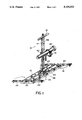
FIG. 1 shows an orthogonal view of a water canon assembly constructed in accordance with this invention;
FIG. 2 shows a side view of the assembly of FIG. 1;
FIG. 3 shows side sectional view of an alternate embodiment of the invention;
FIG. 4 shows a front view of the upright used in the embodiment of FIG. 3;
FIG. 5 shows a side view of the upright of FIG. 4;
FIG. 6 shows a top view of the upright of FIGS. 4 and 5;
FIG. 7 shows an enlarged side-sectional view of water cartridge constructed in accordance with this invention to be used in the assembly of FIGS. 1-6; and
FIG. 8 shows a side view of the water canon itself.
Referring now to the Figures, an assembly 10 consists of a base 12 with a vertical upright 14 terminating in a transversal handle 16. A platform 18 is mounted reciprocatively in the upright 14 for holding a water cannon 20.
Preferably base 12 consists of a main body 22 and four legs 24 extending laterally from the base to increase the effective support area and stability of the base 12. Legs 24 may be mounted rigidly to main body 22, or alternatively, each leg 24 may be mounted to the body 22 by a pivoting means such as a screw and nut arrangement. In this later configuration, the legs may be folded close to body 22, as shown by arrows 26. In this configuration the assembly 10 occupies less volume, and is easier to store or transport. Base 12 also has a round plate 28 used to secure upright 14 to base 12.
The cannon assembly shown in FIGS. 1 and 2 is best suited to be positioned on a hard surface whereby it achieves stability by opening the legs 24. Another assembly made of similar parts is shown in FIGS. 3-6. This assembly 10, includes an upright 14, with a handle 16 and a reciprocating platform 18 for supporting a water cannon 20 just like in the assembly 10 shown in FIGS. 1 and 2. However in this assembly 10', the upright 12 is secured to triangular plate 70. Plate 70 in turn is secured to an elongated spike 72 terminating in point 74. Assembly 10' is more suited for positioning the cannon on a soft surface, such as grass or dirt, by burying the spike 72.
The cannon assemblies described above are used to fire a water cartridge 80 which may be arranged and constructed as shown in FIG. 7. Cartridge 80 includes an elongated cylindrical housing 82 made of plastic material such as polyethylene. At one end the cartridge is closed off with a plug 84 which is also made of polyethylene and is secured to the housing 82 for example by welding. Plug 84 has an end cap 86 made of a strong, rigid material such as brass. End cap 86 is formed with a central hole 88. Plug 84 is formed with a concave inner surface 90 with a hole 92 passing from surface 90 to hole 88 as shown. Surface 90 defines an air space 96. Within hole 92 and extending into air space 96 is an electric match 94 having two leads 98, 98. Match 94 may be for example an M-100 Electric Match made by the I.C.I. Aerospace company of Valley Forge, Pa. The plug 84 has an enlarged crown 100 with a diameter which is slightly larger than the diameter of housing 82. Adjacent to plug 84 and air space 96, the cartridge is loaded with a suitable amount of smokeless gun powder 102 shaped into a cylinder as shown. Adjacent to the gunpowder 102, there is a disk-shaped insert 104 formed with a circumferential groove 106. Preferably insert 104 is also made of plastic polyethylene and is welded in place.
The opposite end of housing 82 there is a front end plug 108 having a plurality of grooves 110, and also made of polyethylene. Preferably plug 108 is crimped in place. To insure that the housing 82 is water tight, an 0-ring 112 is disposed in at least one of the grooves 110. Between insert 104 and plug 108, the cartridge 80 is filled with a liquid 114. This liquid 114 may consist for example of a solution of 50/50 water and methanol. This solution has a much lower freezing temperature than water so that the cartridge can be used in cold climates. Of course for warm climates, plain water may be used. Preferably the space 116 between plug 108 and insert 104 is only partially filled with liquid 114 thereby leaving an air space 118 to permit the liquid 114 to thermally expand and contract when the ambient temperature changes. Otherwise, the cartridge may be burst.
Finally, cannon 20 includes a cylindrical barrel 120 threaded as at 122. Preferably, threads 122 are not continuous, but are interrupted. A breech 124 is threadedly mounted on the barrel 120, and is formed with a hole 126. The breech 124 and barrel 120 cooperate to hold and secure a cartridge 80 for example by capturing crown 100 therebetween. Leads 98 can be passed through hole 126. To insure that the breech is mounted on the barrel 120 properly aligning marks 128, 130, are provided. The aligning marks indicate the match between the interrupted thread on the breech and the barrel. The interrupted thread is provided to facilitate loading and unloading the cannon. The thread is designed to permit a one-quarter turn (or less) of the breech to mount or dismount the same from the barrel.
The operation of the assembly is as follows. Base 12 used for a flat surface, (or the base shown in FIGS. 4-6 for a soft surface) upright 14, and platform 18 together form a stand for the cannon 20. The stand is positioned and the platform pivoted, raised or lowered so that the cannon is pointing toward a target such as the known or suspected position of the detonator of a bomb (not shown). A cannon 20 is positioned on platform 18 and clamped in place by chain 50. Alternatively the cannon can be secured to the platform 18 before the stand is positioned. Preferably the cannon has been preloaded with a cartridge 80 so that once the cannon is mounted and aimed it is ready to be fired. The leads 98 of match 94 are then connected to an electric source such as a battery or hand-held current generator (not shown). Electric current from the source activates match 94 which in turn detonates powder 102. The detonated powder in turn ejects insert 104 out of the barrel which in turn pushes the liquid 114 (and incidently plug 108) out of the barrel, the liquid being shaped into a narrow high pressure stream for deactivating the bomb detonator. Once the cannon is discharged, the breech is removed with the aid of the rod and spanner dowels and the remains of the cartridge can be quickly cleaned out, for example, by pushing a rod 130 into the barrel 120 as shown in FIG. 8. The cannon can then be reloaded with another cartridge 80.
Obviously numerous modifications may be made to this invention without departing from the scope of the invention as defined in the appended claims.
Claims (18)
1. A water cannon assembly comprising:
a base;
an upright secured to and extending vertically from said base and having a length and a side;
a platform mounted on said one side of said upright, said platform being movable vertically substantially along the length of said upright;
disposable cartridge means disposed in said cannon and including a liquid and ejecting means for selectively ejecting said liquid from said cannon in a concentrated stream; and
clamping means including a cradle secured to said platform and a clamping member, said cradle and clamping member being constructed and arranged to hold said cannon therebetween.
2. The assembly of claim 1 wherein said base is arranged and constructed to rest on a planar surface.
3. The assembly of claim 1 wherein said base is arranged and constructed for embedding in a soft surface.
4. The assembly of claim 1 wherein said cannon includes barrel means and breech means mounted on said barrel means and cooperating to capture said cartridge means.
5. The assembly of claim 4 wherein said breech and barrel are coupled by an interrupted thread arrangement cooperating to allow the breech to be mounted by no more than a quarter turn.
6. The assembly of claim 1 wherein said cartridge means includes an elongated housing containing a liquid, and an explosive separated from said liquid and adapted to project said liquid from said cannon when set off.
7. The assembly of claim 1 wherein said base comprises a flat body attached to said upright, and a plurality of legs extending laterally away from said body.
8. The assembly of claim 1 wherein said base comprises a plate secured to said upright and a stake extending downwardly form said plate.
9. The assembly of claim 1 wherein said upright has a longitudinal slot, and said platform includes upright engaging means extending through said slot for selectively securing said platform to said upright.
10. The assembly of claim 1 wherein said clamping means includes chain means for training around said cannon and tightening means for tightening said chain means.
11. The assembly of claim 1 wherein said cartridge comprises a cylindrical housing including a first end and a second end opposite said first end; a first plug secured to said first end; explosive means disposed adjacent to said first plug; insert means disposed adjacent to said explosive means; a second plug disposed at said second end; and a liquid disposed in a space defined between said insert and said second plug.
12. The assembly of claim 11 wherein said liquid consists of a mixture of water and methanol.
13. The assembly of claim 11 wherein said housing, said first plug, and said insert are made of a plastic, said first plug and said insert being welded to said housing.
14. A water cannon assembly kit comprising:
a first base for mounting a water cannon on a flat surface;
a second base for mounting said water cannon on a soft surface;
upright means selectively secured to one of said first and second bases and having a length and a side;
platform means reciprocatively mounted on said side, said platform being movable vertically substantially along said length and including cannon securing means;
a cannon securable to said platform means by said cannon securing means; and
disposable cartridge means arranged and constructed to fit into said cannon, said cartridge means including a cavity with a liquid, and liquid ejecting means for selectively ejecting said liquid when said cartridge is disposed in said cannon.
15. The kit of claim 14 further including cannon cleaning means for cleaning the cannon after a cartridge has been fired.
16. The kit of claim 14 wherein said platform means has coupling means on one side for mounting said platform means on said upright means.
17. The assembly of claim 1 wherein said platform is pivotable with respect to said upright.
18. The assembly of claim 1 wherein said platform may be secured at substantially any position along said upright.
Applications Claiming Priority (1)
| Application Number | Priority Date | Filing Date | Title |
|---|---|---|---|
| US55753090A | 1990-06-24 | 1990-06-24 |
Related Parent Applications (1)
| Application Number | Title | Priority Date | Filing Date |
|---|---|---|---|
| US55753090A Continuation | 1990-06-24 | 1990-06-24 |
Publications (1)
| Publication Number | Publication Date |
|---|---|
| US5134921A true US5134921A (en) | 1992-08-04 |
Family
ID=24225795
Family Applications (1)
| Application Number | Title | Priority Date | Filing Date |
|---|---|---|---|
| US07/762,654 Expired - Fee Related US5134921A (en) | 1990-06-24 | 1991-09-19 | Water cannon for neutralizing explosive devices, and replaceable cartridge therefor |
Country Status (1)
| Country | Link |
|---|---|
| US (1) | US5134921A (en) |
Cited By (31)
| Publication number | Priority date | Publication date | Assignee | Title |
|---|---|---|---|---|
| US5386758A (en) * | 1993-09-13 | 1995-02-07 | Conley; Kenneth A. | Apparatus and method for disarming pipe bombs |
| US5460154A (en) * | 1993-09-10 | 1995-10-24 | Earth Resources Corporation | Method for pneumatically propelling a projectile substance |
| US5715803A (en) * | 1993-04-30 | 1998-02-10 | Earth Resources Corporation | System for removing hazardous contents from compressed gas cylinders |
| US5743246A (en) * | 1993-09-10 | 1998-04-28 | Earth Resources Corporation | Cannon for disarming an explosive device |
| US5826631A (en) * | 1984-11-08 | 1998-10-27 | Earth Resources Corporation | Cylinder rupture vessel |
| US5868174A (en) * | 1997-07-28 | 1999-02-09 | Earth Resources Corporation | System for accessing and extracting contents from a container within a sealable recovery vessel |
| US5900216A (en) * | 1996-06-19 | 1999-05-04 | Earth Resources Corporation | Venturi reactor and scrubber with suckback prevention |
| US6119574A (en) * | 1998-07-02 | 2000-09-19 | Battelle Memorial Institute | Blast effects suppression system |
| US6164344A (en) | 1997-07-28 | 2000-12-26 | Earth Resources Corporation | Sealable recovery vessel system and method for accessing valved containers |
| US6240981B1 (en) | 1993-05-28 | 2001-06-05 | Earth Resources Corporation | Apparatus and method for controlled penetration of compressed fluid cylinders |
| US6490957B1 (en) * | 1999-11-19 | 2002-12-10 | Battelle Memorial Institute | Explosives disrupter |
| US6681675B2 (en) | 2000-03-03 | 2004-01-27 | Teledyne Brown Engineering, Inc. | Remote hazardous devices interdiction process and apparatus |
| US20040132383A1 (en) * | 2002-08-14 | 2004-07-08 | Langford Mark A. | Fluid jet cutting system |
| US7313881B1 (en) * | 2004-11-08 | 2008-01-01 | The United States Of America As Represented By The Secretary Of The Navy | Pneumatic launcher system and method for operating same |
| US20080011152A1 (en) * | 2006-07-11 | 2008-01-17 | Peter Weiss | Device for disrupting improvised explosive devices (IEDS) |
| US20090178548A1 (en) * | 2006-05-16 | 2009-07-16 | Blastech Ltd. | Detonation interrupter |
| US20100319526A1 (en) * | 2008-04-24 | 2010-12-23 | Imholt Timothy J | Systems and methods for mitigating a blast wave |
| CN1695751B (en) * | 2005-01-20 | 2011-01-12 | 陶泽文 | Deluge gun water caught along track |
| US8677902B1 (en) * | 2011-03-30 | 2014-03-25 | Thomas Michael Rock | Precision water jet disruptor delivery system |
| US9200881B1 (en) * | 2011-10-24 | 2015-12-01 | F. Richard Langner | Systems and methods for an improved firing assembly |
| US9322625B1 (en) | 2011-10-24 | 2016-04-26 | F. Richard Langner | Systems and methods for launching water from a disrupter cannon |
| US9958245B1 (en) | 2017-05-24 | 2018-05-01 | National Chung Shan Institute Of Science And Technology | Liquid disruptor device, method of manufacturing the same, and liquid disruptor device module |
| US10071810B1 (en) * | 2017-02-09 | 2018-09-11 | F. Richard Langner | Methods and apparatus for a parachute retainer |
| US10126106B1 (en) * | 2016-10-01 | 2018-11-13 | F. Richard Langner | Methods and apparatus for releasably coupling shock tube to a disrupter |
| US10451378B2 (en) | 2018-02-14 | 2019-10-22 | The United States of America as represented by the Federal Bureau of Investigation, Department of Justice | Reverse velocity jet tamper disrupter enhancer |
| US10495433B1 (en) * | 2018-02-03 | 2019-12-03 | F. Richard Langner | Methods and apparatus for disarming an explosive device |
| US10712140B2 (en) * | 2017-03-09 | 2020-07-14 | Zero Point, Incorporated | Bumper system for an explosive ordnance disposal disruptor |
| US10794660B2 (en) | 2018-02-14 | 2020-10-06 | The United States of America as represented by the Federal Bureau of Investigation, Department of Justice | Reverse velocity jet tamper disrupter enhancer with muzzle blast suppression |
| US11262155B2 (en) * | 2019-08-09 | 2022-03-01 | The United States of America as represented by the Federal Bureau of Investigation, Department of Justice | Fluid jet stabilizing projectile for enhanced IED disrupters |
| US11421971B2 (en) | 2020-06-02 | 2022-08-23 | The United States of America as represented by the Federal Bureau of Investigation, Department of Justice | Rounded projectiles for target disruption |
| US11933580B2 (en) | 2019-08-09 | 2024-03-19 | The United States of America as represented by the Federal Bureau of Investigation, Department of Justice | Shaped charges for focusing a fluid mass |
Citations (6)
| Publication number | Priority date | Publication date | Assignee | Title |
|---|---|---|---|---|
| US3225656A (en) * | 1964-09-14 | 1965-12-28 | John T Flaherty | Field rifle rest |
| US4169403A (en) * | 1978-08-04 | 1979-10-02 | Hanson Ralph W | Bomb circuit disrupting device and method |
| DE2907759A1 (en) * | 1979-02-28 | 1980-09-04 | Bergwerksverband Gmbh | Water gun for removing corroded bolts or screws - has cartridge containing explosive and quantity of water divided by membrane |
| GB2083894A (en) * | 1980-09-18 | 1982-03-31 | Ester Gerd | Gun for neutralising explosives and the like |
| US4909152A (en) * | 1987-08-08 | 1990-03-20 | Mauser-Werke Oberndorf Gmbh | Cartridge for the expulsion of liquids under pressure |
| US4957027A (en) * | 1989-10-02 | 1990-09-18 | The United States Of America As Represented By The Secretary Of The Navy | Versatile nonelectric dearmer |
-
1991
- 1991-09-19 US US07/762,654 patent/US5134921A/en not_active Expired - Fee Related
Patent Citations (6)
| Publication number | Priority date | Publication date | Assignee | Title |
|---|---|---|---|---|
| US3225656A (en) * | 1964-09-14 | 1965-12-28 | John T Flaherty | Field rifle rest |
| US4169403A (en) * | 1978-08-04 | 1979-10-02 | Hanson Ralph W | Bomb circuit disrupting device and method |
| DE2907759A1 (en) * | 1979-02-28 | 1980-09-04 | Bergwerksverband Gmbh | Water gun for removing corroded bolts or screws - has cartridge containing explosive and quantity of water divided by membrane |
| GB2083894A (en) * | 1980-09-18 | 1982-03-31 | Ester Gerd | Gun for neutralising explosives and the like |
| US4909152A (en) * | 1987-08-08 | 1990-03-20 | Mauser-Werke Oberndorf Gmbh | Cartridge for the expulsion of liquids under pressure |
| US4957027A (en) * | 1989-10-02 | 1990-09-18 | The United States Of America As Represented By The Secretary Of The Navy | Versatile nonelectric dearmer |
Non-Patent Citations (6)
| Title |
|---|
| Brochure: Canon disrupteur Disrupter Gun. * |
| Brochure: EOD Disruptor Model 1870 and Accesirues. * |
| Brochure: Model E Electrical Disrupters. * |
| Brochure: On Target with Neutrex. * |
| Brochure: Spanish Water Disrupter. * |
| Pedsco Disrupter for Improvised Explosive Devices Model PE 101. * |
Cited By (42)
| Publication number | Priority date | Publication date | Assignee | Title |
|---|---|---|---|---|
| US5826631A (en) * | 1984-11-08 | 1998-10-27 | Earth Resources Corporation | Cylinder rupture vessel |
| US5715803A (en) * | 1993-04-30 | 1998-02-10 | Earth Resources Corporation | System for removing hazardous contents from compressed gas cylinders |
| US6240981B1 (en) | 1993-05-28 | 2001-06-05 | Earth Resources Corporation | Apparatus and method for controlled penetration of compressed fluid cylinders |
| US5460154A (en) * | 1993-09-10 | 1995-10-24 | Earth Resources Corporation | Method for pneumatically propelling a projectile substance |
| US5743246A (en) * | 1993-09-10 | 1998-04-28 | Earth Resources Corporation | Cannon for disarming an explosive device |
| US5785038A (en) * | 1993-09-10 | 1998-07-28 | Earth Resources Corporation | Cannon for disarming an explosive device |
| US5386758A (en) * | 1993-09-13 | 1995-02-07 | Conley; Kenneth A. | Apparatus and method for disarming pipe bombs |
| US6139806A (en) * | 1996-06-19 | 2000-10-31 | Earth Resources Corporation | Venturi reactor and scrubber with suckback prevention |
| US5900216A (en) * | 1996-06-19 | 1999-05-04 | Earth Resources Corporation | Venturi reactor and scrubber with suckback prevention |
| US6308748B1 (en) | 1997-07-28 | 2001-10-30 | Earth Resources Corporation | Sealable recovery vessel system and method for accessing valved containers |
| US6164344A (en) | 1997-07-28 | 2000-12-26 | Earth Resources Corporation | Sealable recovery vessel system and method for accessing valved containers |
| US5868174A (en) * | 1997-07-28 | 1999-02-09 | Earth Resources Corporation | System for accessing and extracting contents from a container within a sealable recovery vessel |
| US6119574A (en) * | 1998-07-02 | 2000-09-19 | Battelle Memorial Institute | Blast effects suppression system |
| US6490957B1 (en) * | 1999-11-19 | 2002-12-10 | Battelle Memorial Institute | Explosives disrupter |
| US6644166B2 (en) | 1999-11-19 | 2003-11-11 | Battelle Memorial Institute | Explosives disrupter |
| US6681675B2 (en) | 2000-03-03 | 2004-01-27 | Teledyne Brown Engineering, Inc. | Remote hazardous devices interdiction process and apparatus |
| US20040132383A1 (en) * | 2002-08-14 | 2004-07-08 | Langford Mark A. | Fluid jet cutting system |
| US7313881B1 (en) * | 2004-11-08 | 2008-01-01 | The United States Of America As Represented By The Secretary Of The Navy | Pneumatic launcher system and method for operating same |
| CN1695751B (en) * | 2005-01-20 | 2011-01-12 | 陶泽文 | Deluge gun water caught along track |
| US20090178548A1 (en) * | 2006-05-16 | 2009-07-16 | Blastech Ltd. | Detonation interrupter |
| US7481146B2 (en) * | 2006-07-11 | 2009-01-27 | Peter Weiss | Device for disrupting improvised explosive devices (IEDS) |
| US20080011152A1 (en) * | 2006-07-11 | 2008-01-17 | Peter Weiss | Device for disrupting improvised explosive devices (IEDS) |
| US20100319526A1 (en) * | 2008-04-24 | 2010-12-23 | Imholt Timothy J | Systems and methods for mitigating a blast wave |
| US7878103B2 (en) * | 2008-04-24 | 2011-02-01 | Raytheon Company | Systems and methods for mitigating a blast wave |
| US8677902B1 (en) * | 2011-03-30 | 2014-03-25 | Thomas Michael Rock | Precision water jet disruptor delivery system |
| US9322625B1 (en) | 2011-10-24 | 2016-04-26 | F. Richard Langner | Systems and methods for launching water from a disrupter cannon |
| US9200881B1 (en) * | 2011-10-24 | 2015-12-01 | F. Richard Langner | Systems and methods for an improved firing assembly |
| US10126106B1 (en) * | 2016-10-01 | 2018-11-13 | F. Richard Langner | Methods and apparatus for releasably coupling shock tube to a disrupter |
| US10071810B1 (en) * | 2017-02-09 | 2018-09-11 | F. Richard Langner | Methods and apparatus for a parachute retainer |
| US11092414B2 (en) | 2017-03-09 | 2021-08-17 | Zero Point, Incorporated | Bumper system for an explosive ordnance disposal disruptor |
| US10712140B2 (en) * | 2017-03-09 | 2020-07-14 | Zero Point, Incorporated | Bumper system for an explosive ordnance disposal disruptor |
| US9958245B1 (en) | 2017-05-24 | 2018-05-01 | National Chung Shan Institute Of Science And Technology | Liquid disruptor device, method of manufacturing the same, and liquid disruptor device module |
| US10760888B1 (en) * | 2018-02-03 | 2020-09-01 | Concept Development Corporation | Methods and apparatus for disarming an explosive device |
| US10495433B1 (en) * | 2018-02-03 | 2019-12-03 | F. Richard Langner | Methods and apparatus for disarming an explosive device |
| US10451378B2 (en) | 2018-02-14 | 2019-10-22 | The United States of America as represented by the Federal Bureau of Investigation, Department of Justice | Reverse velocity jet tamper disrupter enhancer |
| US10760872B2 (en) * | 2018-02-14 | 2020-09-01 | The United States Of America As Represented By The Federal Bureau Of Investigation Department Of Justice | Reverse velocity jet tamper disrupter enhancer |
| US10794660B2 (en) | 2018-02-14 | 2020-10-06 | The United States of America as represented by the Federal Bureau of Investigation, Department of Justice | Reverse velocity jet tamper disrupter enhancer with muzzle blast suppression |
| US20200056858A1 (en) * | 2018-02-14 | 2020-02-20 | The United States of America as represented by the Federal Bureau of Investigation, Dept. of Justice | Reverse Velocity Jet Tamper Disrupter Enhancer |
| US11262155B2 (en) * | 2019-08-09 | 2022-03-01 | The United States of America as represented by the Federal Bureau of Investigation, Department of Justice | Fluid jet stabilizing projectile for enhanced IED disrupters |
| US11933580B2 (en) | 2019-08-09 | 2024-03-19 | The United States of America as represented by the Federal Bureau of Investigation, Department of Justice | Shaped charges for focusing a fluid mass |
| US11421971B2 (en) | 2020-06-02 | 2022-08-23 | The United States of America as represented by the Federal Bureau of Investigation, Department of Justice | Rounded projectiles for target disruption |
| US11898830B2 (en) | 2020-06-02 | 2024-02-13 | The United States of America as represented by the Federal Bureau of Investigation, Department of Justice | Rounded projectiles for target disruption |
Similar Documents
| Publication | Publication Date | Title |
|---|---|---|
| US5134921A (en) | Water cannon for neutralizing explosive devices, and replaceable cartridge therefor | |
| US5136920A (en) | Water cannon for neutralizing explosive devices, and replaceable cartridge therefor | |
| US7066365B2 (en) | Transportable shooting apparatus | |
| US5039052A (en) | Portable weapon rack | |
| US4697226A (en) | Light mounting for firearms | |
| US6644166B2 (en) | Explosives disrupter | |
| US5370240A (en) | Dual shooters bow and gun stand | |
| US7857279B2 (en) | Bow holder and bow cradle | |
| US5903995A (en) | Monopod | |
| US9322625B1 (en) | Systems and methods for launching water from a disrupter cannon | |
| US6920713B1 (en) | Gun support for hunters | |
| US4393614A (en) | Gun rest | |
| US20020134365A1 (en) | Net launching tool apparatus | |
| US3017874A (en) | Bow magazine | |
| US5016380A (en) | Weapon apparatus | |
| US9546844B2 (en) | Converted muzzleloader arrow gun | |
| US20100219302A1 (en) | Portable Gun and Crossbow Holder | |
| US20190219370A1 (en) | Portable target system | |
| US4442620A (en) | Fast muzzle-loading device | |
| US6726162B1 (en) | Bow holder | |
| US20090189030A1 (en) | Bow Holder and Bow Cradle | |
| US4229897A (en) | Muzzle loading apparatus | |
| US6289819B1 (en) | Paint ball land mine | |
| US5044590A (en) | Portable weapon rack | |
| US20070119094A1 (en) | Mole gun |
Legal Events
| Date | Code | Title | Description |
|---|---|---|---|
| REMI | Maintenance fee reminder mailed | ||
| LAPS | Lapse for failure to pay maintenance fees | ||
| FP | Lapsed due to failure to pay maintenance fee |
Effective date: 19960807 |
|
| STCH | Information on status: patent discontinuation |
Free format text: PATENT EXPIRED DUE TO NONPAYMENT OF MAINTENANCE FEES UNDER 37 CFR 1.362 |