US6675386B1 - Apparatus for video access and control over computer network, including image correction - Google Patents
Apparatus for video access and control over computer network, including image correction Download PDFInfo
- Publication number
- US6675386B1 US6675386B1 US08/923,091 US92309197A US6675386B1 US 6675386 B1 US6675386 B1 US 6675386B1 US 92309197 A US92309197 A US 92309197A US 6675386 B1 US6675386 B1 US 6675386B1
- Authority
- US
- United States
- Prior art keywords
- video
- remote site
- remote
- cameras
- camera
- Prior art date
- Legal status (The legal status is an assumption and is not a legal conclusion. Google has not performed a legal analysis and makes no representation as to the accuracy of the status listed.)
- Expired - Lifetime
Links
Images


Classifications
-
- H—ELECTRICITY
- H04—ELECTRIC COMMUNICATION TECHNIQUE
- H04N—PICTORIAL COMMUNICATION, e.g. TELEVISION
- H04N7/00—Television systems
- H04N7/16—Analogue secrecy systems; Analogue subscription systems
- H04N7/173—Analogue secrecy systems; Analogue subscription systems with two-way working, e.g. subscriber sending a programme selection signal
- H04N7/17309—Transmission or handling of upstream communications
- H04N7/17318—Direct or substantially direct transmission and handling of requests
-
- H—ELECTRICITY
- H04—ELECTRIC COMMUNICATION TECHNIQUE
- H04N—PICTORIAL COMMUNICATION, e.g. TELEVISION
- H04N21/00—Selective content distribution, e.g. interactive television or video on demand [VOD]
- H04N21/20—Servers specifically adapted for the distribution of content, e.g. VOD servers; Operations thereof
- H04N21/21—Server components or server architectures
- H04N21/218—Source of audio or video content, e.g. local disk arrays
- H04N21/21805—Source of audio or video content, e.g. local disk arrays enabling multiple viewpoints, e.g. using a plurality of cameras
-
- H—ELECTRICITY
- H04—ELECTRIC COMMUNICATION TECHNIQUE
- H04N—PICTORIAL COMMUNICATION, e.g. TELEVISION
- H04N21/00—Selective content distribution, e.g. interactive television or video on demand [VOD]
- H04N21/20—Servers specifically adapted for the distribution of content, e.g. VOD servers; Operations thereof
- H04N21/21—Server components or server architectures
- H04N21/222—Secondary servers, e.g. proxy server, cable television Head-end
- H04N21/2221—Secondary servers, e.g. proxy server, cable television Head-end being a cable television head-end
-
- H—ELECTRICITY
- H04—ELECTRIC COMMUNICATION TECHNIQUE
- H04N—PICTORIAL COMMUNICATION, e.g. TELEVISION
- H04N21/00—Selective content distribution, e.g. interactive television or video on demand [VOD]
- H04N21/20—Servers specifically adapted for the distribution of content, e.g. VOD servers; Operations thereof
- H04N21/23—Processing of content or additional data; Elementary server operations; Server middleware
- H04N21/234—Processing of video elementary streams, e.g. splicing of video streams, manipulating MPEG-4 scene graphs
- H04N21/2343—Processing of video elementary streams, e.g. splicing of video streams, manipulating MPEG-4 scene graphs involving reformatting operations of video signals for distribution or compliance with end-user requests or end-user device requirements
- H04N21/23439—Processing of video elementary streams, e.g. splicing of video streams, manipulating MPEG-4 scene graphs involving reformatting operations of video signals for distribution or compliance with end-user requests or end-user device requirements for generating different versions
-
- H—ELECTRICITY
- H04—ELECTRIC COMMUNICATION TECHNIQUE
- H04N—PICTORIAL COMMUNICATION, e.g. TELEVISION
- H04N21/00—Selective content distribution, e.g. interactive television or video on demand [VOD]
- H04N21/40—Client devices specifically adapted for the reception of or interaction with content, e.g. set-top-box [STB]; Operations thereof
- H04N21/45—Management operations performed by the client for facilitating the reception of or the interaction with the content or administrating data related to the end-user or to the client device itself, e.g. learning user preferences for recommending movies, resolving scheduling conflicts
- H04N21/462—Content or additional data management, e.g. creating a master electronic program guide from data received from the Internet and a Head-end, controlling the complexity of a video stream by scaling the resolution or bit-rate based on the client capabilities
- H04N21/4622—Retrieving content or additional data from different sources, e.g. from a broadcast channel and the Internet
-
- H—ELECTRICITY
- H04—ELECTRIC COMMUNICATION TECHNIQUE
- H04N—PICTORIAL COMMUNICATION, e.g. TELEVISION
- H04N21/00—Selective content distribution, e.g. interactive television or video on demand [VOD]
- H04N21/40—Client devices specifically adapted for the reception of or interaction with content, e.g. set-top-box [STB]; Operations thereof
- H04N21/47—End-user applications
- H04N21/475—End-user interface for inputting end-user data, e.g. personal identification number [PIN], preference data
- H04N21/4758—End-user interface for inputting end-user data, e.g. personal identification number [PIN], preference data for providing answers, e.g. voting
-
- H—ELECTRICITY
- H04—ELECTRIC COMMUNICATION TECHNIQUE
- H04N—PICTORIAL COMMUNICATION, e.g. TELEVISION
- H04N21/00—Selective content distribution, e.g. interactive television or video on demand [VOD]
- H04N21/40—Client devices specifically adapted for the reception of or interaction with content, e.g. set-top-box [STB]; Operations thereof
- H04N21/47—End-user applications
- H04N21/478—Supplemental services, e.g. displaying phone caller identification, shopping application
- H04N21/4782—Web browsing, e.g. WebTV
-
- H—ELECTRICITY
- H04—ELECTRIC COMMUNICATION TECHNIQUE
- H04N—PICTORIAL COMMUNICATION, e.g. TELEVISION
- H04N21/00—Selective content distribution, e.g. interactive television or video on demand [VOD]
- H04N21/60—Network structure or processes for video distribution between server and client or between remote clients; Control signalling between clients, server and network components; Transmission of management data between server and client, e.g. sending from server to client commands for recording incoming content stream; Communication details between server and client
- H04N21/61—Network physical structure; Signal processing
- H04N21/6106—Network physical structure; Signal processing specially adapted to the downstream path of the transmission network
- H04N21/6125—Network physical structure; Signal processing specially adapted to the downstream path of the transmission network involving transmission via Internet
-
- H—ELECTRICITY
- H04—ELECTRIC COMMUNICATION TECHNIQUE
- H04N—PICTORIAL COMMUNICATION, e.g. TELEVISION
- H04N21/00—Selective content distribution, e.g. interactive television or video on demand [VOD]
- H04N21/60—Network structure or processes for video distribution between server and client or between remote clients; Control signalling between clients, server and network components; Transmission of management data between server and client, e.g. sending from server to client commands for recording incoming content stream; Communication details between server and client
- H04N21/61—Network physical structure; Signal processing
- H04N21/6156—Network physical structure; Signal processing specially adapted to the upstream path of the transmission network
- H04N21/6175—Network physical structure; Signal processing specially adapted to the upstream path of the transmission network involving transmission via Internet
-
- H—ELECTRICITY
- H04—ELECTRIC COMMUNICATION TECHNIQUE
- H04N—PICTORIAL COMMUNICATION, e.g. TELEVISION
- H04N21/00—Selective content distribution, e.g. interactive television or video on demand [VOD]
- H04N21/60—Network structure or processes for video distribution between server and client or between remote clients; Control signalling between clients, server and network components; Transmission of management data between server and client, e.g. sending from server to client commands for recording incoming content stream; Communication details between server and client
- H04N21/65—Transmission of management data between client and server
- H04N21/658—Transmission by the client directed to the server
- H04N21/6587—Control parameters, e.g. trick play commands, viewpoint selection
-
- H—ELECTRICITY
- H04—ELECTRIC COMMUNICATION TECHNIQUE
- H04N—PICTORIAL COMMUNICATION, e.g. TELEVISION
- H04N7/00—Television systems
- H04N7/16—Analogue secrecy systems; Analogue subscription systems
- H04N7/173—Analogue secrecy systems; Analogue subscription systems with two-way working, e.g. subscriber sending a programme selection signal
- H04N7/17309—Transmission or handling of upstream communications
- H04N7/17336—Handling of requests in head-ends
-
- H—ELECTRICITY
- H04—ELECTRIC COMMUNICATION TECHNIQUE
- H04N—PICTORIAL COMMUNICATION, e.g. TELEVISION
- H04N7/00—Television systems
- H04N7/18—Closed-circuit television [CCTV] systems, i.e. systems in which the video signal is not broadcast
- H04N7/183—Closed-circuit television [CCTV] systems, i.e. systems in which the video signal is not broadcast for receiving images from a single remote source
- H04N7/185—Closed-circuit television [CCTV] systems, i.e. systems in which the video signal is not broadcast for receiving images from a single remote source from a mobile camera, e.g. for remote control
Definitions
- This invention relates to the distribution of audiovisual signals through communications networks such as computer networks and servers.
- the invention has particular use with respect to global networks such as the internet and “World Wide Web”.
- the invention also relates to education.
- the invention provides an alternative to in-person classroom instruction.
- the present invention relates to the fields of education, audiovisual systems, communications systems and computer networks.
- Video and audio signals are commonly transmitted over broadcast communications media to provide viewers with news and entertainment.
- Computer networks are used for the remote exchange of data and other information. Broadly speaking, these systems are attempts to communicate useful knowledge between geographically separate individuals and institutions.
- the invention generally relates to improvements in the transmission of information between remote locations.
- audiovisual presentations have begun to be used in the field of education. These systems may provide playback of a recording of a lecturer who provides a presentation on an educational topic. For example, students may learn about math from watching a videotape or television broadcast of a math professor's lecture. Education can also occur on a more informal basis. For example, specialty channels in the United States such as the Discovery Channel® and The Learning Channel® (headquartered in Bethesda, Md., U.S.A.) broadcast educational programming which both entertains and educates a diverse viewership.
- Discovery Channel® and The Learning Channel® headquartered in Bethesda, Md., U.S.A.
- Cable and broadcast television are commonly known media which supply information to large numbers of viewers equipped with receivers known as “television sets.” By receiving a broadcast, cablecast or satellite signal, users are able to view scenes from remote locations and observe newsworthy events which occur far from the user's location.
- conventional television is a one-way media in which users cannot communicate with each other or the broadcaster.
- the internet is a large computer network which connects “host” computers. Users with a computer, modem and telephone line commonly call via telephone to connect with a “host.” The “host,” being in communication with other hosts (connected to other users) is able to transfer information between users.
- the internet is used, for example, to transfer, data files, still images, sounds and messages between virtually any two points in the world with telephone access.
- What is needed is a medium of communication that is interactive and which carries audio, video, text, and graphics.
- video is collected at a remote site.
- video includes stereophonic or monophonic audio signals which may accompany a video signal. Additionally, “video” is used broadly herein to include still images, groups of related still images, animation, graphics, pictures, or other visual data.
- the remote video information may be obtained from a video cassette, CD ROMs, television channels, one or more video cameras, or other well known sources. If video cameras are used, they may be connected to a computer so that they are remotely controllable, or they may be oriented such that a perception of control can be created for users.
- the video may relate to remote sites of interest, such as a pyramid in Egypt, or the images may relate to an educational lecture being conducted at a remote site.
- the collected video is transferred to a web site, either in compressed or uncompressed form.
- the video may be physically transported or may be transmitted through a communications medium to the web site.
- the web site contains a storage media which may store some or all of the video. Additionally, the web site passes camera control commands, if applicable, to the remotely controlled cameras or may simulate the remote control of a camera.
- the main function of the web site is to pass video to a plurality of users, through a communication media such as the internet, in response to user selections.
- the video passed to the plurality of users may be live video being fed to the web site, or may be stored video.
- a number of video servers are used to output the video to the users through the communications media, such as the internet.
- the video may be tailored by the web site for the particular user's hardware, including data communication equipment, or memory size, etc . . . , i.e. the data rate matches the highest speed which the user's equipment can handle.
- Users receive and display the video sent from the web site. Many simultaneous video pictures may be received. Of course, the quality and frame rate of the video is dependent on the user's communications hardware. Users with high-speed modems or cable modems receive higher quality video.
- the users are able to send commands and/or queries to the web site. The commands and queries are forwarded to remote locations to control remote cameras or query remotely located instructors. Alternatively, the commands cause the web site to change from among many video signals with different camera angles or locations (or to transmit a different portion of a wide angle image), causing the user to have a perception of remote camera control.
- the user's commands may also cause a different portion of a received wide angle image to be displayed, giving the user a perception of camera control.
- the web site provides information, such as graphics and text, which is related to the video. This information may be automatically supplied, or provided upon user request. Therefore, the user is provided with a comprehensive set of information concerning remote sites, enabling the user to be quickly educated about the remote site of interest.
- FIG. 1 is a block diagram of an embodiment of the invention where remote video is provided to a web server by videocassette and by ordinary television.
- FIG. 2 is a block diagram of an embodiment of the invention where remote video is provided by remotely located cameras and a communication network carries the video to the web server.
- FIGS. 3A and 3B are a block diagrams of an embodiment of the invention using the embodiments of FIGS. 1 and 2 with remotely controllable cameras.
- FIG. 4 shows remote cameras positioned around a building for perceived camera control.
- FIGS. 5A, 5 B, 5 C, and 5 D show video images from specific cameras shown in FIG. 4 .
- FIG. 6 shows remote cameras deployed to follow a parade route.
- FIGS. 7A and 7B show remotely controlled cameras at a remote location.
- FIGS. 8A and 8B show a single remote camera at a remote location, where the camera has a 180 degree spherical (or other wide angle) lens.
- FIGS. 9A and 9B are block diagrams of a server platform.
- FIG. 10 is a block diagram of communications paths from the server site to remote users.
- FIG. 11 shows a home page in accordance with an embodiment of the invention.
- FIG. 12 shows a “society” page in accordance with another embodiment of the invention.
- FIG. 13 shows a “map” page of remote camera locations throughout the world.
- FIG. 14 shows a “watch” page containing live video feeds from five remote cameras.
- FIG. 15 shows a page directed to determining the user's data rate.
- FIG. 16 shows a page of an interactive lecture.
- FIGS. 17 and 18 show pages of an embodiment of the invention which combines live video, prestored video, graphics, and interactive questions.
- FIG. 19 shows a flow diagram of a method of automatically monitoring and panning an area using perceived camera control.
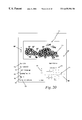
- FIG. 20 is an exemplary screen display of the present invention, showing video and also showing video data.
- FIG. 21 is a diagram showing the interaction between a computer network embodiment of the present invention and a cable television system.
- the present invention is related to obtaining video from remote sites and interactively presenting that video to users.
- the video is obtained at a remote site, communicated to a web site (where it may be stored), and forwarded to users.
- FIG. 1 shows a preferred embodiment of the invention where remote video sources are videocassette and television programs.
- FIG. 1 shows remote sites 102 , remote cameras 104 , videocassette 106 , compression devices 108 , 114 , digital storage device 110 and web site 112 .
- a video camera 104 is used to film activity at remote site 102 .
- numerous video cameras at a single remote site may be used to obtain different views and audio (preferably stereophonic) of the remote site from different angles and orientations.
- numerous remote sites, each with its own video camera may used as shown at 102 ′, 102 ′′ and 104 ′ and 104 ′′.
- the video cameras film events at the remote sites, and record the events on videocassette 106 or other suitable media.
- the recorded information is then transported to a web site 112 , or to a site in communication with web site 112 .
- the recorded information from video tape 106 is then compressed in compression unit 108 and stored in digital storage media 110 .
- Many compression algorithms may be used, such as MPEG-1, MPEG-2 and Wavelet. Compression systems currently available from The Duck Corp, Xing Technology Corp., Indeo, Digital Video Arts, Ltd., VDOnet Corp. and Intel Corp., may be used with the system.
- the digital storage media may be any known storage device, such as a hard disk, CD ROM, digital video disc (DVD), digital tape, video file server or other media.
- the stored and compressed audio/video is then provided on a number of streamed audio-video outputs 116 from the web site 112 .
- This enables many users to access the stored video and audio, and allows for one user to receive numerous audio-video signals, i.e. split the display into numerous “camera” feeds.
- the web site 112 may provide audio and video from television channels.
- the television signals are received by a conventional television receiver (not shown), and digitally compressed by the compression unit 114 and fed through the web site 112 to the streamed output. It is not normally necessary to store the television programs in a digital storage unit (such as the storage unit 110 ), since the audio and video is constantly incoming and changing. However, certain segments of broadcast television may be stored in a storage device (not shown) for recall by a user.
- FIG. 2 shows another embodiment of the invention where similar reference numerals indicate items that correspond to the items shown in FIG. 1 .
- the system of FIG. 2 uses remote cameras and a communication network to provide remote video to the web site.
- FIG. 2 shows remote sites 102 , video cameras 104 , compression unit 118 , data communication network 120 , web site 130 , digital storage unit 132 , and streamed video 116 .
- remote sites 102 are filmed by cameras 104 (as in FIG. 1 ). However, in this embodiment, the output of the cameras 104 pass through a compression unit 118 . The compressed audio and video is communicated over data communication network 120 to web site 130 .
- the data communication network 120 may be any network currently known to one of ordinary skill in the art, such as land-leased lines, satellite, fiber optic cable, microwave link or any other suitable network.
- Suitable networks may be cellular networks or paging networks.
- cameras 104 may be connected to a paging device and/or digital storage media or paging transmitter for communication of the video (including still images) to the web site 130 .
- the web site 130 in this example is adapted to receive information from the data communication network 120 .
- the web site may pass the video from cameras 104 to users at streamed video outputs 116 .
- the web site may contain a decompressor to decompress the video prior to streaming it to users, or change the compression scheme of the video to one which is compatible with the connected user.
- the video may be compressed at the streamed video output and users who connect to the web site 130 may run decompression software.
- the web site 130 may store the audio and video received over data communication network 120 in digital storage unit 132 before providing it to the streamed outputs 116 .
- the audio and video may be directly passed to the streamed outputs 116 .
- FIG. 3A shows another embodiment of the invention that combines the embodiments of FIGS. 1 and 2 and adds remote camera control.
- FIG. 3A shows remote sites 102 , cameras 104 , computer 134 , video path 122 , 129 , control path 124 , 126 , 128 , compressors 108 , 114 , 118 , 136 data communication network 120 , web site 140 , digital storage means 132 , and streamed video 116 .
- remote sites 102 are filmed by camera 104 .
- the web site 140 is able to receive video tape 106 , compress the audio and video in compression unit 108 , and store the compressed audio and video 110 . Audio and video from television stations may also be compressed by compression unit 114 and stored or passed as streamed video 116 , as in FIG. 1 .
- the cameras 104 may be connected to compression unit 118 (as in FIG. 2) and communicate compressed audio and video to web site 140 via data communication network 120 .
- compression unit 118 as in FIG. 2
- FIGS. 1 and 2 may be combined in a variety of manners at a single web site 140 .
- FIGS. 3A and 3B add the additional feature of camera control to the previously described embodiments.
- a computer 134 is connected to remote camera 104 .
- the computer is able to control a mechanical or electrical device on the camera 104 , to alter the camera's orientation (including position and/or angle). Audio and video from the camera 104 passes to the, computer 134 .
- the video may be processed and stored in the computer.
- the computer is connected to multiple remote cameras 104 ′ and 104 ′′ so that multiple users may each control a camera.
- the computer 134 may either contain a compressor or be connected to an external compression unit 136 .
- the video from cameras 104 ′ and 104 ′′ is compressed and provided to data communications network 120 .
- This compressed video is subsequently received by web site 140 .
- the remote cameras 104 ′, 104 ′′ (FIG. 3B) may be controlled by control signals passed from computer 134 on path 124 .
- the control signals are received by computer 134 from the data communications network 120 over the camera control path 126 .
- the web site 140 provides the control information to the data communications network 120 over path 128 .
- the web site 140 of this example is adapted to pass control signals to cameras 104 and to store video images in a digital storage means 132 .
- the web site provides a number of streamed video outputs 116 as in the other examples.
- This embodiment allows remote users to control the angle or orientation of cameras 104 ′, 104 ′′.
- Users are connected to the web site 140 and receive the streamed video 116 from the cameras 104 ′, 104 ′′. If the users wish to move the camera 104 ′, 104 ′′ to the right, they may enter a user command (such as “pan right”) at their terminal.
- the command is received by the web site 140 , and formatted, if necessary.
- the command is outputted to the data communication network 120 as a control signal through the camera control path 128 .
- the remote computer 134 receives the camera control signals from the communication network 120 over camera control path 126 .
- the remote computer 134 may be adapted to control multiple cameras at multiple locations 102 , or multiple cameras at the same location 102 .
- the computer 134 is connected to the remote camera 104 by a camera control path 124 .
- This path allows control commands from the computer to travel to the cameras 104 ′, 104 ′′ and control the cameras 104 ′, 104 ′′.
- the cameras 104 ′, 104 ′′ may have computer-controlled swivel motors (not shown) for panning left and right, may have a computer-controlled pivot motor (not shown) for panning up and down, and may have a computer-controlled motor (not shown) for moving a zoom lens. These motors are known to the artisan and are currently available.
- a plurality of cameras may be provided at a single site to allow multiple users to have camera control at the same time.
- This system of obtaining and/or storing video at a web site is extremely flexible.
- the system allows for perceived camera control by multiple cameras, actual camera control of one or more cameras, perceived camera control via a wide-angle lens on a single camera, and for the generation of comprehensive interactive programs.
- FIGS. 4-6 users are given the perception of camera control.
- a plurality of fixed cameras 104 , 150 , 152 , 153 , 154 , 156 , 158 , 160 , 162 are disposed around a remote site 102 .
- FIGS. 4-6 show this concept in greater detail.
- a building 146 is being prepared for demolition. Disposed around the building 146 are cameras 104 , 150 , 152 , 153 , 154 , 156 , 158 , 160 , 162 , connected to a computer 135 .
- the computer 135 is connected to a communication network 120 (not shown).
- the video from cameras 104 , 150 , 152 , 153 , 154 , 156 , 158 , 160 , 162 is digitized and preferably compressed prior to communication over network 120 , either by compressors connected to the cameras (not shown) or by a compressor connected to the computer 135 (not shown).
- the cameras may be digital cameras or analog cameras connected to an analog-to-digital converter.
- the cameras specifically identified around the periphery are cameras 150 , 152 , 153 , 154 , 156 , 158 , 160 , and 162 .
- the building contains the letter “A” and the letter “B” on two sides as shown at 144 and 148 in FIGS. 4 and 5.
- a number of additional cameras 104 are disposed about the periphery of the building in a circular pattern. The pattern and number of cameras are not critical, but will control how the user perceives movement of the “camera”.
- a video camera 150 faces side A
- a video camera 152 is between sides A and B
- a video camera 153 faces side B
- a video camera 154 is between side B and the side opposite side A.
- the video cameras 156 , 158 , 160 and 162 are disposed closer to the building, as shown. All the video cameras contain audio pickups (preferably stereo). Additionally, all the video cameras are connected to a computer 135 which outputs compressed audiovisual signals to the communication network 120 and consequently to the web site.
- the system shown in FIG. 4 may be implemented by the systems shown in either FIG. 2 or FIG. 3 . Any number of users in communication with the web site 130 , 140 may receive the audio and video from these cameras.
- FIG. 5A shows a typical screen view 150 of the video presented to remote users who are connected to the web site of the present invention.
- the user is observing live video from camera 150 , which provides a view of the building on side A.
- a “toolbar” of commands 151 is presented to the user, including a pan left command “ ⁇ ”, a pan right command “ ⁇ ”, a pan up command “ ⁇ ” and a pan down command “ ⁇ ”.
- An “autopan” command is used in conjunction with another command (such as pan right). The “autopan” command is used to automatically move the picture position in the direction previously entered.
- “autopan” is entered after “pan right,” then the picture will keep panning right until another key is pressed or a default key (such as the ESCape key) is pressed.
- the speed of the “autopan” function is controlled by the “speed” command, which is used in conjunction with the “+” and “ ⁇ ” commands. Additionally, the “+” and “ ⁇ ” commands, when used alone, control a “zoom-in” and “zoom-out” function, respectively.
- the “toolbar” commands are selected via a user input device, which may be a keyboard, mouse, trackball, remote control, etc . . .
- the web site receives the command, and in response, causes the video from the camera positioned to the right of the camera 150 , in this case the video camera 152 (FIG. 4) to be transmitted to the user.
- the user observes the picture appearing in FIG. 5B, which appears to be a view to the right from the previous position (camera 150 ). If the user continues to pan right, he is presented with the FIG. 5C view, received from the camera 153 . The user may continue to pan right all away around the building in this manner.
- the user has special functions available, such as “autopan” and “zoom.”
- “autopan” in conjunction with “pan right” would cause the view of the building to rotate, at a speed dictated by the “speed” function and the “+” and “ ⁇ ” keys.
- Using the “+” and “ ⁇ ” keys alone causes the view to change to a closer camera (“+”) or a camera further away (“ ⁇ ”).
- the cameras 156 , 158 , 160 and 162 are disposed closer to the building than cameras 150 , 152 , 153 and 154 .
- a “magnified” image, obtained from the camera 156 is shown in FIG. 5 D. If no cameras are disposed closer or further away, digital image processing may be used to digitally increase or reduce the size of the image.
- the software which controls these functions may be disposed either at the web server or on the user's computer.
- users may obtain different views of the building 146 as if they were remotely controlling the positioning of a single remote camera.
- the users may observe the demolition of the building from many exciting perspectives.
- This “perceived” camera control is advantageous because it allows any number of users to “control” a camera.
- a single camera which is remotely controllable is only controllable by a single user.
- the present invention is suitable for large audiences. The realism of this perceived control is directly dependent upon the number of cameras and their distances from the viewed object.
- any number of users may pan around the building in real time as if they were actually present at the site.
- the video cameras pick up, preferably in stereo, the sounds of the demolition. Users who have loudspeakers connected to their computer may experience the demolition almost as if they were present.
- FIG. 6 shows a deployment of a number of cameras 104 which are arranged in a linear fashion around a point of interest, each camera connected to computer 135 as in FIG. 4 .
- this embodiment uses “perceived” camera control which may be achieved by the systems shown in FIGS. 2 or 3 .
- the remote location and point of interest is a parade, such as a New Year's Day Parade.
- a user may traverse the length of the parade without actually being present. Users may view whichever part of the parade they are interested in, for as long as they desire, without worry that they have missed an interesting band or float.
- the camera deployment merely follows the parade route.
- Parents who have children in a band or float may search for the child and follow the child throughout the parade route, rather than having to monitor every moment of the parade on television in the hopes that the child will pass the reviewing camera when the parents are watching.
- the parents merely “move” from different cameras along the parade route as their children progress in the parade.
- FIGS. 7A and 7B show another embodiment, where a number of cameras 160 , 162 , 164 , 166 , are provided. These cameras are in direct communication with and are controlled by computer 170 . Although it is possible to form a ring of cameras to perform “perceived” camera control (as in FIGS. 4 - 6 ), the embodiment shown uses four cameras 160 , 162 , 164 , 166 which contain motors 105 (FIG. 7B) for controlling the camera's positioning. The motors are controlled by computer 170 . Either a single computer 170 or a number of computers 170 may be used.
- the remote location and point of interest shown in FIGS. 7A and 7B are, for example, a watering hole or desert oasis.
- the cameras 160 , 162 , 164 , 166 are disposed at an island in the middle of the watering hole.
- the toolbar 151 of FIG. 5 is also used in this embodiment and enables users to choose camera control commands to spin the cameras around or perform other camera functions, such as zoom. Users are therefore able to receive different views and angles, and observe the entire watering hole.
- FIG. 7B shows the control and video paths of the FIG. 7A system combined with system shown in FIGS. 3A and 3B.
- the video from cameras 160 , 162 , 164 , 166 is communicated to computer 170 , in compressed or uncompressed form on path 122 .
- the computer 170 communicates the video to communications network 120 for reception by the web site 140 (FIGS. 3A, 3 B).
- the video is digitized and compressed by either the cameras 160 , 162 , 164 , 166 , the computer 170 , or an external analog-to-digital converter (not shown) and compressor 136 (FIGS. 3A, 3 B) prior to transfer to the communications network 120 .
- Camera control commands are received by the computer 170 on control line 126 , as shown in FIGS. 3A, 3 B and 7 B.
- the commands are formatted, if necessary, by computer 170 and transferred to control units 105 attached to cameras 160 , 162 , 164 , 166 .
- the control units 105 are connected to spin, zoom, or otherwise control the cameras as directed by the user.
- Communications links 124 and 122 may be wired, wireless, digital or analog, and computer 170 may be located nearby or remote from the site 102 .
- FIGS. 7A and 7B are unlike the embodiments shown in FIGS. 4-6, because each user is assigned a remote camera in the FIGS. 7A, 7 B embodiment. Since each user must be assigned their own controllable camera, users will have to contend for available cameras.
- the number of controllable cameras may range from a single camera to any number, and is preferably statistically determined to correlate to the average number of users who access the web server 140 at any given time or at peak times. The number of cameras may be reduced by using known systems which utilize queuing, reservations, and time limits.
- FIGS. 8A and 8B show another embodiment, using only a single camera, where an unlimited number of users may view any portion of the remote site 102 .
- This embodiment uses a spherical lens 182 in optical communication with the camera 180 .
- the remote site 102 shown in FIG. 8 is a remote watering hole or oasis as in FIGS. 7A and 7B.
- a camera 180 has a spherical (or other wide angle) lens 182 , which provides a 180° spherical (or other wide-angle) view.
- This view which is communicated to a computer 184 , contains distortion.
- the computer 184 communicates and compresses the distorted video back to the web site 130 or 140 which stores and may process the image.
- a simple transmitter may be used to convey the entire spherical video to the web site 130 , 140 (FIGS. 2 and 3 ).
- the web site removes the barrel distortion and stores data relating to the entire spherical view. Users may then access different portions of the 180° sphere.
- FIG. 8B shows alternative embodiments of the system shown in FIG. 8 A.
- the spherical (or other wide angle) lens 182 is used with video camera 180 ′′, which conveys video information to computer 184 .
- Computer 184 communicates the video over communications network 120 to the web site 130 .
- the web site 130 may store or process the received video, and make the video available to users at user terminals 302 , 304 , 306 , 308 , 310 by communicating the video over communication network 125 .
- Communication network 125 is explained in more depth below with respect to FIG. 10 .
- processing is conducted on the distorted image to remove the distortion from a segment of the image.
- This processing may be performed at the computer 184 , or the web site 130 , but is preferably performed at the user terminals 302 , 304 , 306 , 308 , 310 .
- the web site 130 has available wide angle video for sending to users. Users display and view only a segment of the wide angle video at a time. Then, by using toolbar 151 (FIG. 5 ), the user may select adjacent segments of the video for view. When a user selects an adjacent segment of the video for display, the adjacent segment is processed to remove distortion and then displayed. Displaying the adjacent segment gives the appearance that the camera was physically “moved” to the adjacent side of the original segment.
- Zimmerman's apparatus uses the following hardware for processing a captured and digitized image: a microcomputer connected to a remote control, computer control, X-Map and Y-Map; an input image buffer connected to the X-Map and Y-Map with an output connected to an image filter and an output image buffer.
- This hardware for example, or any other suitable hardware, may be placed at the computer 184 , or the web site 130 , but is preferably located at the user terminals 302 , 304 , 306 , 308 , 310 .
- the specialized hardware is removed and the hardware functionality is implemented in software at the computer 184 or web site 130 , but preferably the software is loaded into the user terminal 302 , 304 , 306 , 308 , 310 .
- a spherical (or other wide angle) image is supplied to the user's terminal, which executes appropriate software (which may be a “plug-in” for a browser application program) for displaying a segment of the image (or video) without distortion.
- appropriate software which may be a “plug-in” for a browser application program
- the distorted spherical image (or video) may be saved to a storage medium, either at the user's terminal or at the web site, for future loading and viewing.
- FIG. 8B also shows how to remove the lens distortion without special processing.
- a spherical (or other wide angle) lens 182 is in optical communication with a video camera 180 ′.
- a nonlinear imaging sensor 186 is placed between the spherical lens 182 and the video camera 180 ′.
- the imaging sensor is designed to provide a distorted output which cancels out the distortion of the spherical lens 182 , and thus an undistorted wide-angle image is provided to video camera 180 ′.
- imaging sensor 186 may itself provide a digital output, making it unnecessary to use a camera 180 ′. In this case, the imaging sensor 186 would be directly connected to computer 184 .
- imaging sensors 186 are disclosed in U.S. Pat. No. 5,489,940, issued on Feb. 6, 1996 to Richardson et al., and in PCT publication WO 96/12862, published Jun. 13, 1996 to Richardson et al., each incorporated herein by reference. Other suitable imaging sensors may be used with the present invention.
- the image obtained by the imaging sensor 186 may be undistorted and not require further processing. A segment of the image may then be selected for display by simply passing the image data to a display device. If the imaging sensor is imperfect, further processing may occur to correct for defects in the sensor. Additionally, further processing for “zoom” and “unzoom” functions may occur. This further processing may take place at the web site 130 or at the user's terminal 302 , 304 , 306 , 308 , 310 .
- FIGS. 5 through 8 may be used in conjunction with either live audio and video or prerecorded video data (with audio) (shown in FIGS. 1 - 3 ). For example, if nothing interesting is happening at the watering hole, a connected user may access a stored audio and video clip of a lion attack which occurred the day before. If “perceived” camera control is utilized, the stored audio and video preferably includes all camera angles (or a wide-angle view), such that the ability to pan and zoom is preserved.
- FIGS. 9A and 9B show a more detailed view of the web site, listed as web site 140 (FIG. 3 ), but which may also correspond to web sites 112 (FIG. 1) and 130 (FIG. 2 ).
- the web site 140 is connected to a data communication network 120 , the internet 242 , and direct connections 244 .
- the web site contains transmission equipment 210 , receive equipment 220 , 220 ,′ two compression units 108 , 114 , a web server 200 , a router 230 , and communication equipment 240 .
- the web server 200 itself contains a digital matrix switch 250 , a plurality of digital video servers 252 , 252 ′, 252 ′′, 252 ,′′′ a firewall access control unit 254 , a database server 256 , an audio and video storage unit 258 , a data storage unit 260 , an administrative unit 262 , a digital matrix switch 264 , a camera control unit 268 and a digital video matrix switch 270 .
- the web site 140 is connected to the data communication network 120 by transmission equipment 210 and receive equipment 220 . As shown, multiple receivers 220 , 220 ′ may be used. Also, as shown, the receivers may have more than one video output. Audio and video signals may also be input to the web server 200 by videocassette (or other suitable recorded media) or simply by feeding in television programming. As with FIGS. 1 and 3, these signals are preferably compressed by compression units 108 , 114 .
- the web server 200 is connected to remote users by a router 230 and communication equipment 240 , which in turn are connected to the internet 242 or directly connected 244 to users.
- the communications equipment 240 outputs the video streams 116 through a number of input/output ports.
- the web server 200 contains a digital matrix switch 250 , a plurality of digital video servers 252 , 252 ′, 252 ′′, 252 ,′′′ a firewall access control unit 254 , a database server 256 , an audio and video storage unit 258 , a data storage unit 260 , an administrative unit 262 , a digital matrix switch 264 , a camera control unit 268 and a video matrix switch 270 .
- the digital matrix switch 250 receives all incoming compressed video signals from the receivers 220 , 220 ′ and the compressor units 108 , 114 .
- the matrix switch 250 also receives compressed video data from database server 256 .
- the digital matrix switch 250 Under control of the administrative unit 262 , the digital matrix switch 250 outputs the input compressed video signals to digital video servers 252 , 252 ′, 252 ′′, 252 ′′′. In this manner, any input signal can be transferred to any video server as directed by the admin unit.
- stored programming from the database server 256 is routed to the digital matrix switch 250 to be switched as if it were incoming live video.
- the outputs of the digital matrix switch 250 also connect to the database server 256 , so that anything at the inputs, such as incoming live audio and video, can be stored in the database server 256 .
- the compressed input video is passed into various digital video servers 252 , 252 ′, 252 ′′, 252 ′′′ for formatting. Users who connect to web server 200 preferably run their own decompression software so that the no decompression need occur at the web server 200 . As an alternative, the digital video servers may decompress the input video.
- the audio and video from the video servers 252 are passed through a second digital (video) matrix switch 270 . Since switching has already occurred at the digital matrix switch 250 , the second video matrix switch 270 is not required, but is desired for maximum flexibility. It is also optimal where the number of users exceeds the number of video inputs, as one input may be channeled to numerous connected users.
- the matrix switch 270 may contain a processor which joins different frames of video and audio such that each output contains frames for multiple video pictures (including audio). This enables users to receive split screen images of video and select an audio track for playback (see FIG. 14, discussed below).
- the split-screen images may be formed by using known methods, which may differ depending on the type of compression used. For example, digital images may be decompressed, combined with other decompressed images, and then re-compressed; or the images may be decompressed and converted to analog, combined, and then converted to digital and compressed for transmission.
- the signals switched by the video matrix switch 270 are preferably digital. This is because the communicated video streams 116 are preferably digital. It is preferred to process all the signals in the web server in the digital domain to improve simplicity and maintain maximum flexibility.
- the various streams of video output from the video matrix switch 270 are passed to the firewall access control unit 254 for output to the router 230 and the communication equipment 240 .
- any user may receive any signal present at any input, including stored signals within audio and video database 258 or data storage unit 260 . Additionally, any compressed digital signal present at the input to digital matrix switch 250 may be stored in the audio and video storage unit 258 or data storage unit 260 . This is advantageous in the perceived camera control embodiment (FIGS. 4-8) where the web server 200 must output a different video picture to the user upon user request.
- the administrative unit 262 directs the matrix switches 250 and 270 to output the correct video stream to the user. If the user is requesting stored video, the administrative unit directs the database server 256 to provide the video to digital matrix switch 250 . If graphics or textual data are required, the administrative unit 262 directs the database server 256 to output the text or graphics to digital matrix switch 264 .
- the database server 256 may be implemented by using several servers and/or multiport servers.
- the audio and video storage unit 258 and data storage unit 260 may be implemented by using many storage media of different types, such as optical storage devices (i.e. CD-ROM), magnetic disks, magnetic tape, or memory circuits (i.e. RAM/ROM). The number of units depends on the amount of stored data, the number of users, and the desired output speed.
- the database server 256 may be one or multiple units.
- the audio and video storage unit 258 stores (preferably compressed) audio and video presentations, including all relevant camera angles.
- the video servers 252 may also be implemented as one or more servers and/or multiport servers.
- the data storage unit 260 is used to store information relating to audiovisual displays. This information relates to the menu structure and screen displays communicated to connected users. The stored information may also relate to specifically to the audio and video which is currently being displayed and heard. For example, in the demolition embodiment of FIG. 5, a user may click on a “more info” icon, to obtain information on demolition. Such information, which could include statistics on dynamite, for example, would be stored as text or graphics in data storage unit 260 . The “more info” command would be transmitted to the communications equipment 240 , pass through the router 230 , and the firewall access control 254 to administrative unit 262 .
- the administrative unit 262 then directs the database server 256 to recall the relevant information, such as statistics on dynamite, from data storage device 260 and pass the information to digital matrix switch 264 .
- the recalled information is then passed to the firewall access control unit 254 , the router 230 , and the communication equipment 240 for transmission to the proper subscriber.
- the data may be combined with audio and video in the firewall access control unit 254 , or be a separate transmission.
- the communication equipment 240 forwards the user's command (such as “pan right”) to the router 230 , which detects the command and forwards it to the firewall access control unit 254 , which passes it to the administrative unit 262 .
- the administrative unit 262 controls the video being fed to each connected user.
- the administrative unit 262 also responds to user commands by instructing either the matrix switch 250 or the matrix switch 270 to pass a different audiovisual signal from another source (i.e. camera, for example, the camera to the right of the present camera) to the connected user. If the user is receiving a stored image from database 258 , the administrative unit instructs the database server 256 to recall the appropriate video signal.
- commands from the user are received by the communication equipment 240 and forwarded to the router 230 .
- the commands enter the web server 200 via the firewall access control unit 254 , and are passed to the administrative unit 262 .
- the commands may be stored in the administrative unit 262 or passed to the database server 256 . Either way, the commands pass through the camera control unit 268 which formats the commands as necessary for remote camera control.
- the formatted commands are passed to the transmission unit 210 .
- the transmission unit 210 provides the commands to data communication network 120 for reception at remote cameras and CPU 134 (FIG. 3 ).
- the administrative unit 262 determines which segment or quadrant of the audiovisual image is to be supplied to the user in response to the user's command.
- the spherical image is stored in database 258 prior to being output to digital matrix switch 250 .
- the image is split into a number of sections, which when combined form the entire 180° sphere. By using suitable image processing software, the distortion is removed or minimized in each segment.
- the administrative unit 262 in response to a user command, determines which segment of the sphere should be sent to the user.
- the administrative unit then directs the database server 256 to retrieve and output the correct segment to the digital matrix switch 250 .
- the administrative unit 262 is able to ensure that the user receives the correct segment of the spherical image.
- the entire spherical (or other wide angle) video is communicated to the user, and the distortion removed by software at the user's terminal. This minimizes the complexity of the processing necessary at the web site 140 , and allows the user to store the entire spherical (or other wide angle) video.
- the communication equipment 240 is designed to automatically determine the maximum data rate at which information can be transmitted to the connected users.
- the data rate depends on the type of connection the web sites has with the user, and the type of equipment the user is operating.
- the communications equipment uses the maximum data rate possible as sensed from the user's communications. Alternatively, users may enter their data rates when prompted by a menu screen, as shown in FIG. 15 and described below.
- the data rates are then stored in communications equipment 240 .
- the communications equipment 240 may also compress the video streams prior to transmission using any known compression algorithm. Additionally, the communications equipment may remove video frames, preferably prior to compression, such that the resulting data rate is reduced to be compatible with the user.
- FIG. 9B is identical to FIG. 9A, but contains an input interface 225 and an output interface 235 .
- the input interface 225 is used to obtain digital video from other sources, such as a paging system, cellular system, cable television system, etc.
- the output interface connects the web site to other communications systems such as paging systems, cellular systems, or cable television systems.
- the input interface connects to an analog system, it contains suitable analog to digital converters (not shown).
- the output interface connects to an analog system, it contains suitable digital to analog converters (not shown).
- the input interface 225 may obtain images or video from a paging system, and the output interface 225 may be connected to a paging system to broadcast video or images to a selective call receiver.
- the following publications are incorporated by reference, each of which relates video/images to selective call receivers: PCT Publication No. WO 96/07269, published Mar. 7, 1996 by Jambhekar et al., PCT Publication No. WO 96/21173, published Jul. 11, 1996 by Harris et al., and PCT Publication No. WO 96/21205, published Jul. 11, 1996 by Harris et al.
- FIG. 10 shows how the users are connected to the web site, and shows an example of a communications network 125 (FIG. 8B) in detail.
- the connections shown in FIG. 10 apply to the web sites of the previous figures, including the web site 112 (FIG. 1 ), 130 (FIG. 2) and 140 (FIGS. 3 and 9 ).
- FIG. 10 shows how the users are connected to the web site, and shows an example of a communications network 125 (FIG. 8B) in detail.
- the connections shown in FIG. 10 apply to the web sites of the previous figures, including the web site 112 (FIG. 1 ), 130 (FIG. 2) and 140 (FIGS. 3 and 9 ).
- FIG. 10 shows how the users are connected to the web site, and shows an example of a communications network 125 (FIG. 8B) in detail.
- the connections shown in FIG. 10 apply to the web sites of the previous figures, including the web site 112 (FIG. 1 ), 130 (FIG. 2) and 140 (FIGS. 3 and 9
- FIG. 10 shows a server platform 200 , the internet 242 , two direct connection 244 , two traditional internet hosts 272 , 274 , two cable internet hosts 276 , 278 , a satellite-based internet host 280 , a telephone dialup 282 , an ISDN channel 284 , a cable plant 286 , 288 , a satellite system 290 and a plurality of connected user terminals 302 , 304 , 306 , 308 , 310 .
- the web site 112 , 130 , 140 may communicate over the internet 242 to a number of different systems. These systems include a traditional internet host 272 , 274 and a cable headend internet host 276 .
- the traditional internet host 272 , 274 may be connected via a telephone line 282 or an ISDN channel 284 to a plurality of remote user terminals 302 , 304 , respectively.
- the cable internet host 276 may be connected via a cable plant 286 to a remote user 306 .
- the web site is connected via a direct connection 244 to a cable headend internet host 278 or satellite-based internet host 280 .
- the cable headend internet host 278 communicates to a cable plant 288 and a remote user terminal 308 .
- the satellite-based internet host 280 communicates via a satellite 290 to a user terminal 310 .
- the communications equipment 240 (FIG. 9) enables communications with any type of user terminal no matter what the data rate or system. Of course, user terminals with higher data rates will receive higher quality audio and video images.
- FIGS. 11-16 show examples of display pages which are shown at the remote user's terminal.
- the pages and menus are stores in data storage unit 260 (FIG. 9) as graphical and/or textual information.
- FIG. 11 shows an example of a home page, using advantages of the present invention.
- the home page 400 contains a number of advertisements 402 , numerous web links 404 , a society link 406 , options for viewing television programming 408 , a plurality of rapid access entry options 409 including a “World Watch Live” option 410 , and options for clubs 412 .
- the advertisements 402 are useful for the page provider to generate revenue.
- the system is designed such that television programming can be supplied over the internet. Users may view television programming by selecting the home page television option 408 .
- the Magazines 404 are used to provide information concerning specific topics to the user. Users may join a society, having additional membership benefits, through the “society” selection 406 .
- the “World Watch Live” feature 410 part of the rapid access entry options 409 , is selected when users wish to watch live video from remote sites.
- the clubs shown in the club option 412 are selected by users who wish to obtain information related to common areas of interest.
- FIG. 12 shows a society menu 406 , selected from the FIG. 11 home menu page. As shown in FIG. 12 there are options for “World Watch Live” 420 , there is an advertisement 402 , subscription information 424 , and numerous club options 422 . This screen and all the functions selected in response to the displayed options may be provided on a subscription or temporarily free basis.
- FIG. 13 shows one example of a “World Watch Live” menu 440 .
- This menu is used to select remote locations from which to observe live or prerecorded video.
- a map of the world is presented with sites that are available to select for observing live video.
- the screen indicates sites that are active 442 or under construction 444 .
- This menu also contains two advertisements 402 .
- the “World Watch Live” embodiment allows connected users to visit virtually anyplace in the world to learn more about its culture, geography, or environment. Coupled with perceived or actual camera control and associated prestored video, textual and graphical information, a powerful and inexpensive learning tool is realized. This is more closely shown in FIG. 14 .
- FIG. 14 shows a menu 450 which corresponds to the Egyptian site in FIG. 13 .
- This screen concerns “Giza, Egypt”, and contains live video from five cameras.
- camera one 452 there is camera one 452 , cameras two through five 454 , a “Map” option 456 , an “About This Site” option 458 , an “About Egypt” option 460 , an “Upcoming Events” option 462 and a “Remote Control” option 464 .
- Camera one 452 is the default for the main viewing camera. The user may select video image sizes and the number of images to be displayed, limited by the equipment the user is operating. Video from cameras two through five are supplied along with that from camera one to provide alternative sites and viewpoints about the topic of the screen (i.e. Egypt).
- the “Map” option 456 brings the user back to the world map (FIG. 13) to select additional sites.
- the “About This Site” option 458 brings up text, graphics or additional video concerning the site of Giza, Egypt. For example, a professor appears and talks about the origin of the Sphinx (shown by camera 1 ). The embodiment shown in FIG. 16 and described below (interactive lecture) may be combined with the “About This Site” option. Additionally, other video may be displayed in response to selection of “About This Site”. Such video may be a documentary of the Sphinx or discussion about the technology that historians estimate was used to construct the Sphinx.
- the “About Egypt” option 460 brings up graphics, text or additional video concerning Egypt. For example, a map of Egypt with population densities may be shown.
- the option for “Upcoming Events” 462 brings graphics, text or video concerning new events in Egypt. For example, text and newspaper articles concerning the construction of new irrigation canals is displayed.
- “Remote Control” option 464 brings up a command menu (such as the “tool bar” 151 of FIGS. 5A-D) which allows the user to change camera angles or positioning in any of the cameras capable of that effect. The menu would apply to actual or perceived camera control. For example, the user could pan around the Sphinx (camera 1 , shown at 452 ) to observe it from the front, each side, and back.
- this single screen relating to Egypt provides a wealth of information at a single internet address (or web site). It is unnecessary for a user to “link” to other locations on the internet. Audiovisual presentations are displayed, which give the user insight into the people and culture of Egypt. Text, graphics, and additional stored video is available to further educate the user. Camera control (actual or perceived) gives the user the feeling of walking around different locations in Egypt.
- FIG. 15 shows a screen 470 which asks users about their equipment in order to determine the appropriate data rate for communications.
- the screen is not needed and the data rate is determined by communication equipment 240 automatically.
- an advertisement 402 is also shown on this screen.
- FIG. 16 shows an interactive lecture embodiment of the present invention.
- live video 500 of an astronomy professor's lecture is transmitted to connected users.
- the users are able to ask the professor questions 510 and receive answers 512 .
- the live video 500 , questions 510 , and answers 512 are shown to all connected users.
- the users enter questions via keyboard or microphone.
- the user may ask a question via video.
- a split screen video showing both the person asking the question and the lecturer may be presented to all users simultaneously.
- the answers are preferably given by the lecturer, who may observe the question on a remote display.
- the answers may be supplied by the web site as text, graphics, or prestored video.
- the answer may pass through a closed captioning device, be encoded, and displayed on the screen in an answer box 512 .
- questions are sent to the web site 140 as part of the normal user terminal communication.
- the web site 140 receives the question at the communications equipment 240 and forwards the question through router 230 and the firewall/access control unit 254 to the administrative unit 262 .
- the administrative unit 262 determines whether the question can be answered by playing stored video or showing stored text or graphics. If so, the administrative unit 262 directs the database server 256 to recall the appropriate information. The information is then output through the matrix switches 250 , 270 or 264 , under control of the administrative unit, as appropriate.
- the ability of the administrative unit to answer questions depends upon the complexity of its software. Simple, prestored answers to frequently asked or standard questions may be provided in a basic system.
- More advanced systems may utilize an interpreter to analyze the question before providing an answer. For example, frequently asked questions in the astronomy field may be “what is a star?” or “how was the galaxy formed?” In response to these questions, which may even be provided on a menu or list, the administrative unit recalls prestored answers in either video, text, or graphics.
- the question proceeds to the remote lecturer in a similar fashion as the camera control signal (FIG. 3) discussed previously.
- the camera control unit 268 (FIG. 9) is replaced with a question format unit (not shown) which reformats the question under control of the administrative unit 262 .
- Transmitter 210 then transmits a question signal to the location of the remote lecture via the data communication network 120 and the communication paths 126 , 128 .
- the lecturer has a display which shows questions received over the data communication network.
- the lecturer or a number of assistants may select from among many prestored answers in response to a question.
- the remote lecturer has a computer and monitor (not shown) which displays the questions and the available prestored answers.
- the lecturer or assistants then match answers with the questions.
- the prestored answers are preferably forwarded to the individual who asked the associated question. In order for others to learn from the questions, the questions and answers may be provided to all connected users.
- FIGS. 17-18 shows an embodiment of the invention using a combination of live video, stored video, stored graphics, camera control and interactive questioning.
- the live video 550 of camera 1 shown in FIG. 17 relates to a geological site, i.e. the geyser, “Old Faithful”. Since the site is located on a National Park, the display screen has been customized to allow for the selection “About National Parks” 604 .
- the user's command is communicated to the web server 112 , 130 , 140 for analysis by the administrative unit 262 .
- the Administrative unit 262 determines that prestored video and graphics are required, and instructs the database server 256 to output the correct information: video to the matrix switch 250 , and graphics to the matrix switch 264 .
- the matrix switches, 250 , 270 , and 264 under control of the administrative unit 262 , forward the video and graphics to the user through the communication equipment 240 .
- FIG. 18 shows the result at the user terminal.
- the communicated prestored video 560 of a Park Ranger appears on the screen.
- the Park Ranger discusses the topic of National Parks. The discussion occurs in conjunction with a graphical display of the locations of all National Parks, shown at the screen location 570 .
- the user may select other options, such as “Map 600 ” to return to the map of all remote sites, “About This Site” 602 to learn more about the site currently viewed, “More About National Parks” 614 for even more information about National Parks, “Upcoming Events” 606 for a schedule of upcoming events, “Remote Control” 608 for remote (either actual or perceived) control of the camera (i.e. camera 1 ), “Ask Questions” 610 for asking questions (as in FIG. 16) to an on-line Park Ranger, and “Other Topics” 612 , for a list of other topics and/or options.
- “Map 600 ” to return to the map of all remote sites
- “About This Site” 602 to learn more about the site currently viewed
- “More About National Parks” 614 for even more information about National Parks
- “Upcoming Events” 606 for a schedule of upcoming events
- Remote Control 608 for remote (either actual or perceived) control of the camera (i
- the present invention provides an easy and fun way to learn, by combining live video, prestored video, graphics and text with interactive questioning and actual or perceived camera control.
- the present invention may be used in a surveillance or tracking system.
- a researcher may place a video camera in the center of a watering hole, preferably connected to a video recorder for storing many hours of activity at the watering hole.
- a video recorder for storing many hours of activity at the watering hole.
- multiple cameras or a wide-angle lens are used such that virtual camera control (as described previously) may be performed on the video.
- virtual camera control as described previously
- the system allows for automatic scanning of the surveyed area, without the need for moving any cameras. Additionally, multiple segments of the area under surveillance may be viewed at the same time in a split-screen image. All that needs to be done is the removal of distortion in multiple segments of the video (if using a wide-angle lens).
- automatic monitoring and/or tracking may be performed. Often, researchers and photographers wait through long periods of inactivity before a desired event occurs. For example, a photographer may wait for hours for a lion or other wildlife to approach the photographer's position.
- the present invention may be used to automatically monitor a remote region for activity.
- a processor may monitor the multiple cameras or the digital wide-angle video for pixel changes indicating the desired event. For example, an approaching lion in an otherwise inactive desert environment will cause a moving pattern to form on a camera's output or in the wide angle image.
- a processor may detect the pattern and alert a wildlife researcher that an event is occurring.
- the processor may automatically and continually display the relevant camera output, or the segment of the wide angle image containing the lion, thereby tracking the lion.
- the present invention may employ tracking techniques, known in the prior art, to the obtained digital image.
- the monitoring and tracking embodiment of the present invention it may be desirable to remove the distortion from the wide angle image prior to performing the processing to determine whether an event is occurring.
- the type of event being monitored and nature of the object being tracked controls whether monitoring and/or tracking may be performed on the distorted or undistorted image.
- One of ordinary skill in the art will choose the system best suited for the particular monitored event or tracked object.
- FIG. 19 shows a flow diagram of a monitoring and tracking system using the present invention.
- the software necessary to perform the monitoring/tracking functions may be located at the web site or at the user's terminal.
- the image/video signal to be processed for monitoring and/or tracking may be a live video feed or be played back from stored video.
- a wildlife scientist may leave multiple video cameras running overnight (or a single video camera with a wide-angle lens) and when the video tape is played back, the segments/cameras containing activity are displayed.
- an “input frame of reference” routine 700 is executed. This routine is optional, and is used to establish a frame of reference direction, such as north. The frame of reference may determine the first segment of a wide-angle image to view, or the first camera to view.
- a “reset segment counter” routine 710 is executed. This sets the segment or camera to be first displayed.
- a “reset timer” routine 715 is executed to reset the interval when segments or cameras are switched.
- the “obtain image” routine 720 is executed. This routine obtains the wide angle image (live or prerecorded), or images from all the cameras (in the multiple camera perceived control embodiment of FIGS. 4 and 5 ). The obtained image from a wide-angle lens may be processed to remove the distortion or not, depending on what is being monitored.
- the obtained image is processed to determine active areas (cameras or segments). Active areas are ares where the processor determines that activity is taking place, either by changes in the pixels at those locations, by using other known image/video processing techniques, or by using external sensors. The processing is performed as known in the art and is not described further herein. The processing occurs during the “process for activity” routine 730 . This routine uses the frame of reference to determine which segment(s), relative to the normal (i.e. north) is/are active.
- the “display active segments” routine 750 displays the active segments or cameras on a display. Distortion from the relevant segments is removed in the wide-angle lens embodiment. If more than one segment is active, a split screen display may show the each segment simultaneously. The each split screen display may make reference to the frame of reference which was previously entered during routine 700 . The “reset timer” routine 710 is then executed so that the last segment under view is returned when activity is no longer present.
- the “display current segment” routine 760 is executed. This routine displays the current segment or camera until the timer expires, at which point the next segment or camera is displayed. The display may make reference to the frame of reference which was previously entered during routine 700 .
- the “time limit exceeded” routine 770 is executed. If the time limit has not been exceeded, a branch to the “obtain image” routine 720 occurs and processing continues until the time limit is exceeded, or until activity occurs.
- the time limit value may be increased by pressing the “ ⁇ ” button in conjunction with the “speed” button (FIG. 5 ), for a slower autopan, and the time limit may be decreased by pressing the “+” button in conjunction with the “speed” button (FIG. 5) for a faster autopan.
- the segment (or camera) counter is incremented by the “increment segment counter” routine 780 . If the counter is greater than the maximum number of cameras or segments, the “counter>max” routine 790 branches to the “reset segment counter” routine 710 , to restart the automatic panning. If the counter is not greater than allowed, a branch occurs to the “reset timer” routine 715 so that the next segment or camera may be displayed, and processing for activity continues.
- the flow chart of FIG. 19 allows for automatic panning and for automatic tracking. If the “process for activity” routine 730 , the “activity?” test 740 , and the “display active segments” routine 750 were removed, the “autopan” function described previously and shown with respect to FIG. 5 would be achieved. In this case, “display current segment” routine 760 would follow “obtain image” routine 740 .
- Monitoring and automatic panning may be combined. When combined, all active segments or cameras are automatically panned for a brief timeframe. Thus, if a lion and zebra are both moving towards the camera from opposite direction, each would be displayed for a brief timeframe before switching to a display of the other. This is an alternative to the split screen display previously described.
- the user may select or be provided data concerning the video currently displayed.
- data concerning the video currently displayed For example, superimposed on the video may be the date and time the video was recorded, a name of the image location, remaining time for the video, or data pertaining to the segment (or camera source) of the video which is currently being viewed.
- This segment/camera data may be a compass heading (such as north) or angle from a reference (such as 40 degrees), or coordinate information (such as X/Y, X/Y/Z, R/ ⁇ , X/R/ ⁇ etc . . . ) relating to the location of the center of the segment/video currently displayed in relation to the wide angle image or other cameras.
- a graphical representation of the lens may show which segment of the wide angle image (or camera) is being displayed.
- a frame of reference may be adopted, especially for a spherical lens.
- the frame of reference would be either generated by a processor at the web site or user's terminal, or entered by a user or operator. For example, the user may select which direction is “north” or position the axis of a coordinate system if a coordinate display is to be used for a particular lens.
- the display of image data may be used in all embodiments of the present invention, and are preferably updated when the displayed image changes.
- FIG. 20 shows an exemplary display 800 showing a coral reef 805 where users have virtual camera control via multiple underwater cameras.
- the date 810 is displayed along with the time 820 .
- the location is shown at 830 and the remaining time of the program at 840 .
- the magnification is shown at 850 and the density and colors at 860 .
- the segment camera field 870 shows that the user is viewing camera no. 3 .
- This segment/camera data may be shown graphically, as depicted at 880 .
- Field 880 is a top view of the coral reef 805 and the layout of the cameras, in this case cameras 1 through 10 .
- the square around camera no. 3 indicates that this camera is the source of the picture on the display 800 .
- the frame of reference (north) is indicated at 890 for the graphical segment data and 895 for the video data.
- the images, video, and image data may also be stored at the user's terminal (or receiving apparatus).
- the wide angle distorted image is stored, along with the image data, if present. Storage of the image and image data enables the user to retrieve the image and view a segment at a later date.
- the entire interactive presentation may be stored at the user's terminal (including associated graphics, text, video, data, or other information), although all the pertinent files and data would have to be received by the user.
- the video or image may be stored in either its distorted or undistorted state. Storing the video or image in its undistorted state has the advantage in that tall and/or wide pictures may be stored in their most viewable state, and in that editing may be performed on the images more easily if they are retrieved with the distortion removed.
- the perceived camera control of the present invention may also be used in the field of broadcast television or the field of cable television.
- a transmitter may broadcast the images to television receivers.
- the television receivers are equipped with decoders to decode the wide-angle image as, for example only, disclosed in U.S. Pat. No. 5,384,588, issued Jan. 24, 1995 to Martin et al., incorporated herein by reference.
- the broadcast television transmitter (not shown) may be connected to remote cameras 104 (FIGS. 1 - 3 ), output interface 235 (FIG. 9 B), internet hosts 272 , 274 , 276 , 278 , 280 (FIG. 10 ), communications media 120 , 125 (FIG. 8 B), or even a user's terminal 302 , 304 , 306 , 308 , 310 (FIG. 10 ).
- a separate decoder or a cable set top converter box contains the appropriate decoding circuitry.
- a cable television transmitter is connected to remote cameras 104 (FIGS. 1 - 3 ), output interface 235 (FIG. 9 B), internet hosts 272 , 274 , 276 , 278 , 280 (FIG. 10 ), communications media 120 , 125 (FIG. 8 B), or even a user's terminal 302 , 304 , 306 , 308 , 310 (FIG. 10 ).
- the cable television system is preferably, digital, and may easily interact with the present invention.
- FIG. 21 shows the interaction between an embodiment of the present invention 900 and, for example, the general system 910 of the Hendricks et al. '549 patent.
- Digital signals from the present invention relating to ordinary video, stored video, wide-angle video, video from multiple cameras, information of any type and interactive presentations may be provided to various elements of the Hendricks et al. '549 patent 910 . It is understood that such digital signals may be supplied to corresponding elements of traditional analog and digital cable television systems that accept digital signals at an input (i.e. stand-alone or using a digital to analog converter).
- digital video 920 from remote camera 104 and remote wide-angle digital video 930 , processed/compressed digital video 940 from computer 184 , video 950 from communication network 120 , streamed video 960 from web site 140 , video 970 from communications network 125 , and video 980 from the user terminals (i.e. 302 ) may be communicated to the digital cable television system of the '549 Hendricks et al patent.
- These video signals may be received by either the operations center 1000 , satellite 1010 , cable headend 1020 , or set top terminals 1030 of the '549 Hendricks et al patent.
- the operations center 1000 , satellite 1010 , cable headend 1020 , and set top terminals 1030 may communicate digital signals to the internet structure of the present invention. Specifically, these communicated signals may be received by the remote computer 184 , data communication network 120 (including web site 130 ), data communication network 125 , and user terminals (i.e. 302 ).
- the present invention is capable of fully integrating with cable television systems able to transmit and receive digitally.
- the present invention breaks down the barrier between television networks and computer networks, allowing for a single integrated programming system.
Abstract
Description
Claims (26)
Priority Applications (21)
| Application Number | Priority Date | Filing Date | Title |
|---|---|---|---|
| US08/923,091 US6675386B1 (en) | 1996-09-04 | 1997-09-04 | Apparatus for video access and control over computer network, including image correction |
| AT98945841T ATE491303T1 (en) | 1997-09-04 | 1998-09-03 | DEVICE FOR VIDEO ACCESS AND CONTROL OVER A COMPUTER NETWORK WITH IMAGE CORRECTION |
| CA2302616A CA2302616C (en) | 1997-09-04 | 1998-09-03 | Apparatus for video access and control over computer network, including image correction |
| CNB988106248A CN1224258C (en) | 1997-09-04 | 1998-09-03 | Apparatus for video access and control over computer network, including image correction |
| CNA2005100998682A CN1741607A (en) | 1997-09-04 | 1998-09-03 | Apparatus for video access and control over computer network, including image correction |
| EP98945841A EP1025696B1 (en) | 1997-09-04 | 1998-09-03 | Apparatus for video access and control over computer network, including image correction |
| AU92993/98A AU755424B2 (en) | 1997-09-04 | 1998-09-03 | Apparatus for video access and control over computer network, including image correction |
| JP2000509221A JP2001515319A (en) | 1997-09-04 | 1998-09-03 | Video access and control device via computer network including image correction |
| EP03001262A EP1309194A1 (en) | 1997-09-04 | 1998-09-03 | Apparatus for video access and control over computer network, including image correction |
| DE69842037T DE69842037D1 (en) | 1997-09-04 | 1998-09-03 | DEVICE FOR VIDEO ACCESS AND CONTROL VIA A COMPUTER NETWORK WITH IMAGE CORRECTION |
| IL15995898A IL159958A0 (en) | 1997-09-04 | 1998-09-03 | Apparatus for video access and control over computer network, including image correction |
| MXPA00002312A MXPA00002312A (en) | 1997-09-04 | 1998-09-03 | Apparatus for video access and control over computer network, including image correction. |
| RU2000108445/09A RU2219677C2 (en) | 1997-09-04 | 1998-09-03 | Device for video signal access and control through computer network including image correction |
| PCT/US1998/018271 WO1999012349A1 (en) | 1997-09-04 | 1998-09-03 | Apparatus for video access and control over computer network, including image correction |
| IL13488198A IL134881A (en) | 1997-09-04 | 1998-09-03 | Apparatus for video access and control over computer network, including image correction |
| NZ503632A NZ503632A (en) | 1997-09-04 | 1998-09-03 | Accessing video from remote sites via a network |
| BR9812059-0A BR9812059A (en) | 1997-09-04 | 1998-09-03 | Apparatus for communicating video audio signals to user terminals, which provides the perception of remote camera control to a user, to provide users with effective camera control of a video remote camera, for use with a computer network, and for use with the internet, systems to provide a user with perceived camera control via a web site, to provide a user with effective camera control, to obtain and communicate video, and processes to remotely view a remote site, and to provide interactive presentations |
| US09/520,344 US7849393B1 (en) | 1992-12-09 | 2000-03-07 | Electronic book connection to world watch live |
| US10/448,014 US20040010804A1 (en) | 1996-09-04 | 2003-05-30 | Apparatus for video access and control over computer network, including image correction |
| IL159958A IL159958A (en) | 1997-09-04 | 2004-01-20 | Apparatus for video access and control over computer network, including image correction |
| JP2007262539A JP2008113425A (en) | 1997-09-04 | 2007-10-05 | Apparatus for video access and control over computer network, including image correction |
Applications Claiming Priority (3)
| Application Number | Priority Date | Filing Date | Title |
|---|---|---|---|
| US2560496P | 1996-09-04 | 1996-09-04 | |
| US3348596P | 1996-12-20 | 1996-12-20 | |
| US08/923,091 US6675386B1 (en) | 1996-09-04 | 1997-09-04 | Apparatus for video access and control over computer network, including image correction |
Related Child Applications (2)
| Application Number | Title | Priority Date | Filing Date |
|---|---|---|---|
| US19152098A Continuation-In-Part | 1992-12-09 | 1998-11-13 | |
| US10/448,014 Division US20040010804A1 (en) | 1996-09-04 | 2003-05-30 | Apparatus for video access and control over computer network, including image correction |
Publications (1)
| Publication Number | Publication Date |
|---|---|
| US6675386B1 true US6675386B1 (en) | 2004-01-06 |
Family
ID=29740614
Family Applications (2)
| Application Number | Title | Priority Date | Filing Date |
|---|---|---|---|
| US08/923,091 Expired - Lifetime US6675386B1 (en) | 1992-12-09 | 1997-09-04 | Apparatus for video access and control over computer network, including image correction |
| US10/448,014 Abandoned US20040010804A1 (en) | 1996-09-04 | 2003-05-30 | Apparatus for video access and control over computer network, including image correction |
Family Applications After (1)
| Application Number | Title | Priority Date | Filing Date |
|---|---|---|---|
| US10/448,014 Abandoned US20040010804A1 (en) | 1996-09-04 | 2003-05-30 | Apparatus for video access and control over computer network, including image correction |
Country Status (1)
| Country | Link |
|---|---|
| US (2) | US6675386B1 (en) |
Cited By (191)
| Publication number | Priority date | Publication date | Assignee | Title |
|---|---|---|---|---|
| US20010024469A1 (en) * | 1998-07-27 | 2001-09-27 | Avishai Keren | Remote computer access |
| US20020036565A1 (en) * | 1999-02-25 | 2002-03-28 | Monroe David A. | Digital communication system for law enforcement use |
| US20020065076A1 (en) * | 1998-01-12 | 2002-05-30 | David A. Monroe | Apparatus and method for selection of circuit in multi-circuit communications device |
| US20020063799A1 (en) * | 2000-10-26 | 2002-05-30 | Ortiz Luis M. | Providing multiple perspectives of a venue activity to electronic wireless hand held devices |
| US20020071663A1 (en) * | 2000-12-07 | 2002-06-13 | O'donnel John Setel | Digital video recording system having multi-pass video processing |
| US20020087990A1 (en) * | 2000-12-05 | 2002-07-04 | Jim Bruton | System for transmitting data via satellite |
| US20020089587A1 (en) * | 2000-05-18 | 2002-07-11 | Imove Inc. | Intelligent buffering and reporting in a multiple camera data streaming video system |
| US20020097258A1 (en) * | 2000-12-06 | 2002-07-25 | Maymudes David M. | Methods and systems for effecting video transitions represented by bitmaps |
| US20020099789A1 (en) * | 2000-12-06 | 2002-07-25 | Rudolph Eric H. | Methods and systems for processing multi-media editing projects |
| US20020103918A1 (en) * | 2000-12-06 | 2002-08-01 | Miller Daniel J. | Methods and systems for efficiently processing compressed and uncompressed media content |
| US20020138842A1 (en) * | 1999-12-17 | 2002-09-26 | Chong James I. | Interactive multimedia video distribution system |
| US20020167587A1 (en) * | 2001-05-10 | 2002-11-14 | E.C.R Corporation | Monitoring system |
| US20020170064A1 (en) * | 2001-05-11 | 2002-11-14 | Monroe David A. | Portable, wireless monitoring and control station for use in connection with a multi-media surveillance system having enhanced notification functions |
| US20020175995A1 (en) * | 2001-05-26 | 2002-11-28 | Marc Sleeckx | Video surveillance system |
| US20020184641A1 (en) * | 2001-06-05 | 2002-12-05 | Johnson Steven M. | Automobile web cam and communications system incorporating a network of automobile web cams |
| US20030005445A1 (en) * | 1995-10-02 | 2003-01-02 | Schein Steven M. | Systems and methods for linking television viewers with advertisers and broadcasters |
| US20030025599A1 (en) * | 2001-05-11 | 2003-02-06 | Monroe David A. | Method and apparatus for collecting, sending, archiving and retrieving motion video and still images and notification of detected events |
| US20030041162A1 (en) * | 2001-08-27 | 2003-02-27 | Hochmuth Roland M. | System and method for communicating graphics images over a computer network |
| US20030061325A1 (en) * | 2001-09-21 | 2003-03-27 | Monroe David A. | Method and apparatus for interconnectivity between legacy security systems and networked multimedia security surveillance system |
| US20030061344A1 (en) * | 2001-09-21 | 2003-03-27 | Monroe David A | Multimedia network appliances for security and surveillance applications |
| US20030067387A1 (en) * | 2001-10-05 | 2003-04-10 | Kwon Sung Bok | Remote control and management system |
| US20030067542A1 (en) * | 2000-10-13 | 2003-04-10 | Monroe David A. | Apparatus for and method of collecting and distributing event data to strategic security personnel and response vehicles |
| US20030112354A1 (en) * | 2001-12-13 | 2003-06-19 | Ortiz Luis M. | Wireless transmission of in-play camera views to hand held devices |
| US20030163826A1 (en) * | 2002-02-25 | 2003-08-28 | Sentrus, Inc. | Method and system for remote wireless video surveillance |
| US20030164883A1 (en) * | 2002-01-16 | 2003-09-04 | Rooy Jan Van | Production system, control area for a production system and image capturing system for a production system |
| US20030197785A1 (en) * | 2000-05-18 | 2003-10-23 | Patrick White | Multiple camera video system which displays selected images |
| US20030204850A1 (en) * | 2002-04-29 | 2003-10-30 | The Boeing Company | Combining multiple simultaneous source cinema to multiple exhibitor receivers |
| US20040001214A1 (en) * | 1998-01-12 | 2004-01-01 | Monroe David A. | Apparatus for capturing, converting and transmitting a visual image signal via a digital transmission system |
| US20040010801A1 (en) * | 2002-07-13 | 2004-01-15 | Kim Kyong Ho | Video geographic information system |
| US20040056964A1 (en) * | 2002-09-25 | 2004-03-25 | Tomoaki Kawai | Remote control of image pickup apparatus |
| US20040068583A1 (en) * | 2002-10-08 | 2004-04-08 | Monroe David A. | Enhanced apparatus and method for collecting, distributing and archiving high resolution images |
| US20040080608A1 (en) * | 1998-01-12 | 2004-04-29 | Monroe David A. | Method and apparatus for image capture, compression and transmission of a visual image over telephonic or radio transmission system |
| US20040117638A1 (en) * | 2002-11-21 | 2004-06-17 | Monroe David A. | Method for incorporating facial recognition technology in a multimedia surveillance system |
| US6760885B1 (en) * | 2000-06-15 | 2004-07-06 | Microsoft Corporation | System and method for using a standard composition environment as the composition space for video image editing |
| US20040135803A1 (en) * | 2000-12-06 | 2004-07-15 | Miller Daniel J. | Interface and related methods for reducing source accesses in a development system |
| US20040168195A1 (en) * | 2003-02-21 | 2004-08-26 | Lg Electronics Inc. | Digital broadcasting system and operating method thereof |
| US20040189688A1 (en) * | 2000-12-06 | 2004-09-30 | Miller Daniel J. | Methods and systems for processing media content |
| US20040189876A1 (en) * | 2001-06-13 | 2004-09-30 | Norimitu Shirato | Remote video recognition system |
| US20040196502A1 (en) * | 2002-05-07 | 2004-10-07 | Canon Kabushiki Kaisha | Image data processing system |
| US20040210935A1 (en) * | 1995-10-02 | 2004-10-21 | Starsight Telecast, Inc. | Interactive computer system for providing television schedule information |
| US6810526B1 (en) * | 1996-08-14 | 2004-10-26 | March Networks Corporation | Centralized broadcast channel real-time search system |
| US20040220814A1 (en) * | 2000-12-06 | 2004-11-04 | Microsoft Corporation | Methods and systems for mixing digital audio signals |
| US20040221291A1 (en) * | 2000-12-06 | 2004-11-04 | Miller Daniel J. | System and related methods for reducing source filter invocation in a development project |
| US20040230352A1 (en) * | 2002-11-22 | 2004-11-18 | Monroe David A. | Record and playback system for aircraft |
| US20040257384A1 (en) * | 1999-05-12 | 2004-12-23 | Park Michael C. | Interactive image seamer for panoramic images |
| US20040263626A1 (en) * | 2003-04-11 | 2004-12-30 | Piccionelli Gregory A. | On-line video production with selectable camera angles |
| US20050007453A1 (en) * | 2003-05-02 | 2005-01-13 | Yavuz Ahiska | Method and system of simultaneously displaying multiple views for video surveillance |
| US20050028208A1 (en) * | 1998-07-17 | 2005-02-03 | United Video Properties, Inc. | Interactive television program guide with remote access |
| US20050033825A1 (en) * | 2000-12-06 | 2005-02-10 | Microsoft Corporation | Method of sharing a parcer |
| US20050034133A1 (en) * | 2000-12-06 | 2005-02-10 | Microsoft Corporation | Methods and systems for implementing dynamic properties on objects that support only static properties |
| US20050039211A1 (en) * | 2002-09-17 | 2005-02-17 | Kinya Washino | High-quality, reduced data rate streaming video production and monitoring system |
| US20050053357A1 (en) * | 2000-12-06 | 2005-03-10 | Microsoft Corporation | Methods and systems for managing multiple inputs and methods and systems for processing media content |
| US20050060715A1 (en) * | 2000-12-06 | 2005-03-17 | Microsoft Corporation | System and related interfaces supporting the processing of media content |
| US20050060712A1 (en) * | 2000-12-06 | 2005-03-17 | Microsoft Corporation | Systems for generating and managing filter strings in a filter graph |
| US20050057648A1 (en) * | 2003-07-31 | 2005-03-17 | Yasuhito Ambiru | Image pickup device and image pickup method |
| US20050100309A1 (en) * | 2003-01-10 | 2005-05-12 | Vcs Video Communication Systems Ag | Recording method for video/audio data |
| US20050104894A1 (en) * | 2000-06-06 | 2005-05-19 | Microsoft Corporation | System and method for providing vector editing of bitmap images |
| US20050114903A1 (en) * | 2000-02-08 | 2005-05-26 | Sherjil Ahmed | Method and apparatus for a digitized CATV network for bundled services |
| US20050117018A1 (en) * | 1999-11-05 | 2005-06-02 | Wolf Peter H. | Automated camera system |
| US20050125803A1 (en) * | 2000-12-06 | 2005-06-09 | Microsoft Corporation | Systems for negotiating buffer size and attribute characteristics in media processing systems that create user-defined development projects |
| US20050138660A1 (en) * | 1997-09-18 | 2005-06-23 | United Video Properties, Inc. | Electronic mail reminder for an internet television program guide |
| US20050133585A1 (en) * | 1997-09-30 | 2005-06-23 | Canon Kabushiki Kaisha | Information providing system, apparatus method and storage medium |
| US20050190057A1 (en) * | 2001-10-10 | 2005-09-01 | Monroe David A. | Networked personal security system |
| US20050190263A1 (en) * | 2000-11-29 | 2005-09-01 | Monroe David A. | Multiple video display configurations and remote control of multiple video signals transmitted to a monitoring station over a network |
| US20050204288A1 (en) * | 2000-03-20 | 2005-09-15 | Clapper Edward O. | Facilitating access to digital video |
| US20050204331A1 (en) * | 2000-12-06 | 2005-09-15 | Microsoft Corporation | Data structures and related methods for facilitating media content processing in user-defined development projects. |
| US20050207487A1 (en) * | 2000-06-14 | 2005-09-22 | Monroe David A | Digital security multimedia sensor |
| US6950122B1 (en) * | 2002-04-08 | 2005-09-27 | Link Communications, Ltd. | Integrated video data capture system |
| US20050232579A1 (en) * | 1998-08-28 | 2005-10-20 | Monroe David A | Multifunction remote control system for audio and video recording, capture, transmission and playback of full motion and still images |
| US20050267826A1 (en) * | 2004-06-01 | 2005-12-01 | Levy George S | Telepresence by human-assisted remote controlled devices and robots |
| US20060015906A1 (en) * | 1996-12-10 | 2006-01-19 | Boyer Franklin E | Internet television program guide system |
| US20060023066A1 (en) * | 2004-07-27 | 2006-02-02 | Microsoft Corporation | System and Method for Client Services for Interactive Multi-View Video |
| US7015949B1 (en) | 2001-04-12 | 2006-03-21 | Ipix Corporation | Method and apparatus for hosting a network camera with refresh degradation |
| US20060063752A1 (en) * | 2000-03-14 | 2006-03-23 | Boehringer Ingelheim Pharma Gmbh & Co. Kg | Bicyclic heterocycles, pharmaceutical compositions containing them, their use, and processes for preparing them |
| US20060070105A1 (en) * | 1999-11-15 | 2006-03-30 | Tomoaki Kawai | Control of data distribution apparatus and data distribution system |
| US7024488B1 (en) | 2001-04-12 | 2006-04-04 | Ipix Corporation | Method and apparatus for hosting a network camera |
| US20060136972A1 (en) * | 2003-02-11 | 2006-06-22 | Raymond Metzger | System for a plurality of video cameras disposed on a common network |
| US7076085B1 (en) | 2001-04-12 | 2006-07-11 | Ipix Corp. | Method and apparatus for hosting a network camera including a heartbeat mechanism |
| US20060184982A1 (en) * | 1999-07-27 | 2006-08-17 | Microsoft Corporation | Selection compression |
| US7130908B1 (en) | 2001-03-13 | 2006-10-31 | Intelsat Ltd. | Forward cache management between edge nodes in a satellite based content delivery system |
| US20060244831A1 (en) * | 2005-04-28 | 2006-11-02 | Kraft Clifford H | System and method for supplying and receiving a custom image |
| US20060259933A1 (en) * | 2005-05-10 | 2006-11-16 | Alan Fishel | Integrated mobile surveillance system |
| US20060259552A1 (en) * | 2005-05-02 | 2006-11-16 | Mock Wayne E | Live video icons for signal selection in a videoconferencing system |
| US7154898B1 (en) | 2001-03-13 | 2006-12-26 | Intelsat, Ltd. | Scalable edge node |
| US20070019068A1 (en) * | 2005-07-22 | 2007-01-25 | Marc Arseneau | System and Methods for Enhancing the Experience of Spectators Attending a Live Sporting Event, with User Authentication Capability |
| US7174373B1 (en) | 2001-03-13 | 2007-02-06 | Panamsat Corporation | Self-contained demonstration node in a satellite based content delivery system |
| US7177448B1 (en) | 2001-04-12 | 2007-02-13 | Ipix Corporation | System and method for selecting and transmitting images of interest to a user |
| US20070070209A1 (en) * | 2003-04-11 | 2007-03-29 | Piccionelli Gregory A | Video production with selectable camera angles |
| US20070070210A1 (en) * | 2003-04-11 | 2007-03-29 | Piccionelli Gregory A | Video production with selectable camera angles |
| US20070091176A1 (en) * | 2005-10-24 | 2007-04-26 | Avermedia Technologies, Inc. | Method for executing data compression with surveillance hosts |
| US20070094698A1 (en) * | 1999-12-03 | 2007-04-26 | Ourworld Live, Inc. | Consumer access systems and methods for providing same |
| US20070107010A1 (en) * | 2005-11-08 | 2007-05-10 | United Video Properties, Inc. | Interactive advertising and program promotion in an interactive television system |
| US20070107029A1 (en) * | 2000-11-17 | 2007-05-10 | E-Watch Inc. | Multiple Video Display Configurations & Bandwidth Conservation Scheme for Transmitting Video Over a Network |
| US20070109594A1 (en) * | 2003-01-03 | 2007-05-17 | E-Watch Inc. | Apparatus for Capturing, Converting and Transmitting a Visual Image Signal Via A Digital Transmission System |
| WO2007060497A2 (en) * | 2005-11-23 | 2007-05-31 | Grandeye, Ltd. | Interactive wide-angle video server |
| US20070124783A1 (en) * | 2005-11-23 | 2007-05-31 | Grandeye Ltd, Uk, | Interactive wide-angle video server |
| US20070130599A1 (en) * | 2002-07-10 | 2007-06-07 | Monroe David A | Comprehensive multi-media surveillance and response system for aircraft, operations centers, airports and other commercial transports, centers and terminals |
| US7237017B1 (en) | 2001-03-13 | 2007-06-26 | Panamsat Corporation | Micronode in a satellite based content delivery system |
| US20070157276A1 (en) * | 1997-10-23 | 2007-07-05 | Maguire Francis J Jr | Web page based video service and apparatus |
| US20070182840A1 (en) * | 2000-06-14 | 2007-08-09 | E-Watch Inc. | Dual-Mode Camera |
| US7257641B1 (en) * | 2000-03-30 | 2007-08-14 | Microsoft Corporation | Multipoint processing unit |
| US20070216783A1 (en) * | 2000-10-26 | 2007-09-20 | Ortiz Luis M | Providing video of a venue activity to a hand held device through a cellular communications network |
| US20070289920A1 (en) * | 2006-05-12 | 2007-12-20 | Fiberweb, Inc. | Pool and spa filter |
| EP1899967A1 (en) * | 2005-06-29 | 2008-03-19 | Canon Kabushiki Kaisha | Storing video data in a video file |
| US7360230B1 (en) | 1998-07-27 | 2008-04-15 | Microsoft Corporation | Overlay management |
| US20080127264A1 (en) * | 1996-05-03 | 2008-05-29 | Brian Lee Klosterman | Method and system for displaying advertisements in an electronic program guide |
| US20080129821A1 (en) * | 2006-12-01 | 2008-06-05 | Embarq Holdings Company, Llc | System and method for home monitoring using a set top box |
| US20080163355A1 (en) * | 2006-12-27 | 2008-07-03 | Mci Communications Services | Method and apparatus for participating in a virtual community for viewing a remote event over a wireless network |
| US20080158373A1 (en) * | 2006-12-27 | 2008-07-03 | Mci Communications Services | Method and system of providing a virtual community for participation in a remote event |
| US20080172704A1 (en) * | 2007-01-16 | 2008-07-17 | Montazemi Peyman T | Interactive audiovisual editing system |
| US20080184308A1 (en) * | 1998-12-03 | 2008-07-31 | Herrington W Benjamin | Electronic program guide with related-program search feature |
| US20080184305A1 (en) * | 1995-10-02 | 2008-07-31 | Schein Steven M | Systems and methods for contextually linking television program information |
| US20080201505A1 (en) * | 2003-01-08 | 2008-08-21 | Monroe David A | Multimedia data collection device for a host with a single available input port |
| WO2008110158A2 (en) | 2007-03-15 | 2008-09-18 | Mobotix Ag | Surveillance system |
| WO2008144256A1 (en) * | 2007-05-14 | 2008-11-27 | Patent Category Corporation | System, methods, and apparatus for video communications |
| US20080304565A1 (en) * | 2007-06-08 | 2008-12-11 | Sakhardande Amit S | Reducing the network load of event-triggered video |
| US20090009605A1 (en) * | 2000-06-27 | 2009-01-08 | Ortiz Luis M | Providing multiple video perspectives of activities through a data network to a remote multimedia server for selective display by remote viewing audiences |
| US20090113505A1 (en) * | 2007-10-26 | 2009-04-30 | At&T Bls Intellectual Property, Inc. | Systems, methods and computer products for multi-user access for integrated video |
| US20090128631A1 (en) * | 2000-10-26 | 2009-05-21 | Ortiz Luis M | Displaying broadcasts of multiple camera perspective recordings from live activities at entertainment venues on remote video monitors |
| US7551075B1 (en) | 1999-02-25 | 2009-06-23 | David A Monroe | Ground based security surveillance system for aircraft and other commercial vehicles |
| US20090187850A1 (en) * | 2008-01-22 | 2009-07-23 | Chris Hannan | System and method for multi-screen experience |
| US20090225750A1 (en) * | 2008-03-07 | 2009-09-10 | Embarq Holdings Company, Llc | System and Method for Remote Home Monitoring Utilizing a VoIP Phone |
| US20090319601A1 (en) * | 2008-06-22 | 2009-12-24 | Frayne Raymond Zvonaric | Systems and methods for providing real-time video comparison |
| US20100002070A1 (en) * | 2004-04-30 | 2010-01-07 | Grandeye Ltd. | Method and System of Simultaneously Displaying Multiple Views for Video Surveillance |
| US20100002071A1 (en) * | 2004-04-30 | 2010-01-07 | Grandeye Ltd. | Multiple View and Multiple Object Processing in Wide-Angle Video Camera |
| US7698450B2 (en) | 2000-11-17 | 2010-04-13 | Monroe David A | Method and apparatus for distributing digitized streaming video over a network |
| US20100091108A1 (en) * | 2008-10-13 | 2010-04-15 | Boeing Company | System for checking security of video surveillance of an area |
| US20100158533A1 (en) * | 2008-12-23 | 2010-06-24 | At&T Intellectual Property I, L.P. | Remote control device signal distribution |
| US20100223640A1 (en) * | 1999-12-10 | 2010-09-02 | United Video Properties, Inc. | Systems and methods for coordinating interactive and passive advertisement and merchandising opportunities |
| US7823056B1 (en) | 2006-03-15 | 2010-10-26 | Adobe Systems Incorporated | Multiple-camera video recording |
| WO2010130042A1 (en) * | 2009-05-12 | 2010-11-18 | David Latchman | Realtime video network |
| US7839926B1 (en) | 2000-11-17 | 2010-11-23 | Metzger Raymond R | Bandwidth management and control |
| US20100310238A1 (en) * | 1996-10-16 | 2010-12-09 | Gemstar Development Corp. | Access to internet data through a television system |
| US20100310230A1 (en) * | 1998-07-14 | 2010-12-09 | United Video Properties, Inc. | Client-server based interactive television program guide system with remote server recording |
| US20100328467A1 (en) * | 2009-06-24 | 2010-12-30 | Sony Corporation | Movable-mechanical-section controlling device, method of controlling movable mechanical section, and program |
| US20110041150A1 (en) * | 1995-10-02 | 2011-02-17 | Schein Steven M | Method and system for displaying advertising, video, and program schedule listing |
| US20110074577A1 (en) * | 2005-10-21 | 2011-03-31 | Patent Category Corp. | Interactive clothing system |
| FR2953087A1 (en) * | 2009-11-26 | 2011-05-27 | Defiboat Technology | Network cameras e.g. audio and video cameras, control method for simultaneously visualizing different scenes on boat, involves visualizing image data sent by each camera in remote display windows according to requests |
| US7966636B2 (en) | 2001-05-22 | 2011-06-21 | Kangaroo Media, Inc. | Multi-video receiving method and apparatus |
| US20110212682A1 (en) * | 2009-11-16 | 2011-09-01 | Ortiz Luis M | Self-contained data communication system nodes as stand-alone pods or embedded in concrete walkways and in walls at public venues including sports and entertainment venues |
| US8026944B1 (en) * | 2001-04-12 | 2011-09-27 | Sony Corporation | Method and apparatus for hosting a network camera with image degradation |
| US8042140B2 (en) | 2005-07-22 | 2011-10-18 | Kangaroo Media, Inc. | Buffering content on a handheld electronic device |
| US8095956B1 (en) * | 2000-02-25 | 2012-01-10 | Qwest Communications International Inc | Method and system for providing interactive programming |
| US8238695B1 (en) | 2005-12-15 | 2012-08-07 | Grandeye, Ltd. | Data reduction techniques for processing wide-angle video |
| US8264524B1 (en) | 2008-09-17 | 2012-09-11 | Grandeye Limited | System for streaming multiple regions deriving from a wide-angle camera |
| US8272011B2 (en) | 1996-12-19 | 2012-09-18 | Index Systems, Inc. | Method and system for displaying advertisements between schedule listings |
| US8296366B2 (en) | 2004-05-27 | 2012-10-23 | Microsoft Corporation | Efficient routing of real-time multimedia information |
| US8341662B1 (en) * | 1999-09-30 | 2012-12-25 | International Business Machine Corporation | User-controlled selective overlay in a streaming media |
| US20130047096A1 (en) * | 1998-10-19 | 2013-02-21 | Sony Corporation | Information processing apparatus and method, information processing system, and providing medium |
| US20130162844A1 (en) * | 2011-12-22 | 2013-06-27 | Joseph I. Douek | Remote target viewing and control for image-capture device |
| US8583027B2 (en) | 2000-10-26 | 2013-11-12 | Front Row Technologies, Llc | Methods and systems for authorizing computing devices for receipt of venue-based data based on the location of a user |
| US20140049641A1 (en) * | 2003-08-29 | 2014-02-20 | Harlie D. Frost | Radio Controller System And Method For Remote Devices |
| US8761584B2 (en) | 1993-03-05 | 2014-06-24 | Gemstar Development Corporation | System and method for searching a database of television schedule information |
| US8806536B2 (en) | 1998-03-04 | 2014-08-12 | United Video Properties, Inc. | Program guide system with preference profiles |
| US8806533B1 (en) | 2004-10-08 | 2014-08-12 | United Video Properties, Inc. | System and method for using television information codes |
| US8832742B2 (en) | 2006-10-06 | 2014-09-09 | United Video Properties, Inc. | Systems and methods for acquiring, categorizing and delivering media in interactive media guidance applications |
| US8892495B2 (en) | 1991-12-23 | 2014-11-18 | Blanding Hovenweep, Llc | Adaptive pattern recognition based controller apparatus and method and human-interface therefore |
| US8904441B2 (en) | 2003-11-06 | 2014-12-02 | United Video Properties, Inc. | Systems and methods for providing program suggestions in an interactive television program guide |
| EP2334052A3 (en) * | 2009-11-26 | 2015-01-14 | Defiboat Technology | Image data transmission method and corresponding system |
| US9059809B2 (en) | 1998-02-23 | 2015-06-16 | Steven M. Koehler | System and method for listening to teams in a race event |
| US9071872B2 (en) | 2003-01-30 | 2015-06-30 | Rovi Guides, Inc. | Interactive television systems with digital video recording and adjustable reminders |
| US9075861B2 (en) | 2006-03-06 | 2015-07-07 | Veveo, Inc. | Methods and systems for segmenting relative user preferences into fine-grain and coarse-grain collections |
| US9098910B2 (en) | 2008-09-29 | 2015-08-04 | Mobotix Ag | Method for generating video data stream |
| US9125169B2 (en) | 2011-12-23 | 2015-09-01 | Rovi Guides, Inc. | Methods and systems for performing actions based on location-based rules |
| US9141615B1 (en) | 2004-11-12 | 2015-09-22 | Grandeye, Ltd. | Interactive media server |
| US9166714B2 (en) | 2009-09-11 | 2015-10-20 | Veveo, Inc. | Method of and system for presenting enriched video viewing analytics |
| US9191722B2 (en) | 1997-07-21 | 2015-11-17 | Rovi Guides, Inc. | System and method for modifying advertisement responsive to EPG information |
| US20150373296A1 (en) * | 2013-02-27 | 2015-12-24 | Brother Kogyo Kabushiki Kaisha | Terminal Device and Computer-Readable Medium for the Same |
| US9288521B2 (en) | 2014-05-28 | 2016-03-15 | Rovi Guides, Inc. | Systems and methods for updating media asset data based on pause point in the media asset |
| US9294799B2 (en) | 2000-10-11 | 2016-03-22 | Rovi Guides, Inc. | Systems and methods for providing storage of data on servers in an on-demand media delivery system |
| US9319735B2 (en) | 1995-06-07 | 2016-04-19 | Rovi Guides, Inc. | Electronic television program guide schedule system and method with data feed access |
| US9326025B2 (en) | 2007-03-09 | 2016-04-26 | Rovi Technologies Corporation | Media content search results ranked by popularity |
| US9426509B2 (en) | 1998-08-21 | 2016-08-23 | Rovi Guides, Inc. | Client-server electronic program guide |
| WO2016144218A1 (en) * | 2015-03-09 | 2016-09-15 | Telefonaktiebolaget Lm Ericsson (Publ) | Method, system and device for providing live data streams to content-rendering devices |
| US9521371B2 (en) | 2006-12-27 | 2016-12-13 | Verizon Patent And Licensing Inc. | Remote station host providing virtual community participation in a remote event |
| US9535563B2 (en) | 1999-02-01 | 2017-01-03 | Blanding Hovenweep, Llc | Internet appliance system and method |
| US9646444B2 (en) | 2000-06-27 | 2017-05-09 | Mesa Digital, Llc | Electronic wireless hand held multimedia device |
| US9736524B2 (en) | 2011-01-06 | 2017-08-15 | Veveo, Inc. | Methods of and systems for content search based on environment sampling |
| US9749693B2 (en) | 2006-03-24 | 2017-08-29 | Rovi Guides, Inc. | Interactive media guidance application with intelligent navigation and display features |
| US20170272791A1 (en) * | 2002-09-17 | 2017-09-21 | Lightside Technologies LLC | High-Quality, Reduced Data Rate Streaming Video Production and Monitoring System |
| US9807147B1 (en) * | 1999-12-02 | 2017-10-31 | Western Digital Technologies, Inc. | Program recording webification |
| US20170357858A1 (en) * | 2016-06-09 | 2017-12-14 | Qualcomm Incorporated | Geometric matching in visual navigation systems |
| US9992399B2 (en) * | 2016-01-22 | 2018-06-05 | Alex B. Carr | System, method and apparatus for independently controlling different cameras from a single device |
| US10063934B2 (en) | 2008-11-25 | 2018-08-28 | Rovi Technologies Corporation | Reducing unicast session duration with restart TV |
| US10327043B2 (en) * | 2016-07-09 | 2019-06-18 | N. Dilip Venkatraman | Method and system for displaying interactive questions during streaming of real-time and adaptively assembled video |
| CN110891156A (en) * | 2019-10-23 | 2020-03-17 | 视联动力信息技术股份有限公司 | Conference entering method and device of monitoring camera |
| US10893243B1 (en) * | 2018-03-07 | 2021-01-12 | Alarm.Com Incorporated | Lawn violation detection |
| US10929565B2 (en) | 2001-06-27 | 2021-02-23 | Sony Corporation | Integrated circuit device, information processing apparatus, memory management method for information storage device, mobile terminal apparatus, semiconductor integrated circuit device, and communication method using mobile terminal apparatus |
| US10977493B2 (en) * | 2018-01-31 | 2021-04-13 | ImageKeeper LLC | Automatic location-based media capture tracking |
| US11244162B2 (en) * | 2018-10-31 | 2022-02-08 | International Business Machines Corporation | Automatic identification of relationships between a center of attention and other individuals/objects present in an image or video |
| US11501483B2 (en) | 2018-12-10 | 2022-11-15 | ImageKeeper, LLC | Removable sensor payload system for unmanned aerial vehicle performing media capture and property analysis |
Families Citing this family (37)
| Publication number | Priority date | Publication date | Assignee | Title |
|---|---|---|---|---|
| US20020056098A1 (en) * | 1998-06-29 | 2002-05-09 | Christopher M. White | Web browser system for displaying recently viewed television channels |
| US20040075738A1 (en) * | 1999-05-12 | 2004-04-22 | Sean Burke | Spherical surveillance system architecture |
| US7788686B1 (en) * | 2000-03-01 | 2010-08-31 | Andrews Christopher C | Method of and apparatus for describing, promoting, publishing, aggregating, distributing and accessing live content information |
| EP1180863A3 (en) * | 2000-07-13 | 2005-11-23 | Sony Corporation | Method and apparatus for the processing of digital broadcast signals, whereby position information collected by a satellite Global Positioning System (GPS) is multiplexed on a digital broadcast signal |
| US20020010931A1 (en) * | 2000-07-19 | 2002-01-24 | Chew Brian O. | Method of viewing a live event |
| DE10128925A1 (en) * | 2001-06-15 | 2002-12-19 | Deutsche Telekom Ag | Terminal and method for using various services offered over a telecommunications network |
| US7113616B2 (en) * | 2001-12-05 | 2006-09-26 | Hitachi Kokusai Electric Inc. | Object tracking method and apparatus using template matching |
| EP1694071A1 (en) * | 2005-02-11 | 2006-08-23 | Vemotion Limited | Interactive video applications |
| GB0502812D0 (en) * | 2005-02-11 | 2005-03-16 | Vemotion Ltd | Interactive video |
| EP1694060A1 (en) * | 2005-02-17 | 2006-08-23 | Wolf Weitzdörfer | Presentation system |
| KR100772634B1 (en) * | 2006-07-31 | 2007-11-02 | 삼성전자주식회사 | Digital broadcasting system and method thereof |
| WO2008021344A2 (en) * | 2006-08-14 | 2008-02-21 | Fliqz, Inc. | System and method for providing video media on a website |
| US20090049122A1 (en) * | 2006-08-14 | 2009-02-19 | Benjamin Wayne | System and method for providing a video media toolbar |
| US20080129822A1 (en) * | 2006-11-07 | 2008-06-05 | Glenn Daniel Clapp | Optimized video data transfer |
| SG150412A1 (en) * | 2007-09-05 | 2009-03-30 | Creative Tech Ltd | Method and system for customising live media content |
| US20100083341A1 (en) * | 2008-09-30 | 2010-04-01 | Hector Gonzalez | Multiple Signal Output System and Technology (MSOST) |
| US20130218706A1 (en) * | 2012-02-22 | 2013-08-22 | Elwha Llc | Systems and methods for accessing camera systems |
| CA2946727A1 (en) * | 2014-04-23 | 2015-10-29 | President And Fellows Of Harvard College | Telepresence apparatus and method enabling a case-study approach to lecturing and teaching |
| WO2016004258A1 (en) | 2014-07-03 | 2016-01-07 | Gopro, Inc. | Automatic generation of video and directional audio from spherical content |
| CN105988369B (en) * | 2015-02-13 | 2020-05-08 | 上海交通大学 | Content-driven intelligent household control method |
| US10033928B1 (en) | 2015-10-29 | 2018-07-24 | Gopro, Inc. | Apparatus and methods for rolling shutter compensation for multi-camera systems |
| US9792709B1 (en) | 2015-11-23 | 2017-10-17 | Gopro, Inc. | Apparatus and methods for image alignment |
| US9973696B1 (en) | 2015-11-23 | 2018-05-15 | Gopro, Inc. | Apparatus and methods for image alignment |
| US9848132B2 (en) | 2015-11-24 | 2017-12-19 | Gopro, Inc. | Multi-camera time synchronization |
| US9602795B1 (en) | 2016-02-22 | 2017-03-21 | Gopro, Inc. | System and method for presenting and viewing a spherical video segment |
| US9973746B2 (en) | 2016-02-17 | 2018-05-15 | Gopro, Inc. | System and method for presenting and viewing a spherical video segment |
| US9743060B1 (en) | 2016-02-22 | 2017-08-22 | Gopro, Inc. | System and method for presenting and viewing a spherical video segment |
| US9922398B1 (en) | 2016-06-30 | 2018-03-20 | Gopro, Inc. | Systems and methods for generating stabilized visual content using spherical visual content |
| US9934758B1 (en) | 2016-09-21 | 2018-04-03 | Gopro, Inc. | Systems and methods for simulating adaptation of eyes to changes in lighting conditions |
| US10268896B1 (en) | 2016-10-05 | 2019-04-23 | Gopro, Inc. | Systems and methods for determining video highlight based on conveyance positions of video content capture |
| US10043552B1 (en) | 2016-10-08 | 2018-08-07 | Gopro, Inc. | Systems and methods for providing thumbnails for video content |
| US10684679B1 (en) | 2016-10-21 | 2020-06-16 | Gopro, Inc. | Systems and methods for generating viewpoints for visual content based on gaze |
| US10194101B1 (en) | 2017-02-22 | 2019-01-29 | Gopro, Inc. | Systems and methods for rolling shutter compensation using iterative process |
| US10469818B1 (en) | 2017-07-11 | 2019-11-05 | Gopro, Inc. | Systems and methods for facilitating consumption of video content |
| US10587807B2 (en) | 2018-05-18 | 2020-03-10 | Gopro, Inc. | Systems and methods for stabilizing videos |
| US10750092B2 (en) | 2018-09-19 | 2020-08-18 | Gopro, Inc. | Systems and methods for stabilizing videos |
| US20240107137A1 (en) * | 2021-03-19 | 2024-03-28 | Ying Lun Lui | Imaging device and system, method of capturing images and computer readable storage medium |
Citations (32)
| Publication number | Priority date | Publication date | Assignee | Title |
|---|---|---|---|---|
| US5185667A (en) | 1991-05-13 | 1993-02-09 | Telerobotics International, Inc. | Omniview motionless camera orientation system |
| WO1994007327A1 (en) | 1992-09-21 | 1994-03-31 | Rolm Company | Method and apparatus for on-screen camera control in video-conference equipment |
| US5313306A (en) | 1991-05-13 | 1994-05-17 | Telerobotics International, Inc. | Omniview motionless camera endoscopy system |
| US5359363A (en) | 1991-05-13 | 1994-10-25 | Telerobotics International, Inc. | Omniview motionless camera surveillance system |
| US5384588A (en) | 1991-05-13 | 1995-01-24 | Telerobotics International, Inc. | System for omindirectional image viewing at a remote location without the transmission of control signals to select viewing parameters |
| US5467402A (en) * | 1988-09-20 | 1995-11-14 | Hitachi, Ltd. | Distributed image recognizing system and traffic flow instrumentation system and crime/disaster preventing system using such image recognizing system |
| US5489940A (en) | 1994-12-08 | 1996-02-06 | Motorola, Inc. | Electronic imaging system and sensor for correcting the distortion in a wide-angle lens |
| WO1996007269A1 (en) | 1994-09-01 | 1996-03-07 | Motorola Inc. | Interface card with an electronic camera and method of use therefor |
| WO1996008105A1 (en) | 1994-09-09 | 1996-03-14 | Motorola Inc. | Method for creating image data |
| EP0702491A1 (en) | 1994-09-08 | 1996-03-20 | International Business Machines Corporation | Video optimized media streamer with cache management |
| WO1996017306A2 (en) | 1994-11-21 | 1996-06-06 | Oracle Corporation | Media server |
| WO1996021173A1 (en) | 1994-12-29 | 1996-07-11 | Motorola Inc. | Wireless pager with separable receiver unit and transmitter unit |
| WO1996021205A1 (en) | 1994-12-29 | 1996-07-11 | Motorola Inc. | Wireless pager with prestored images |
| US5537141A (en) * | 1994-04-15 | 1996-07-16 | Actv, Inc. | Distance learning system providing individual television participation, audio responses and memory for every student |
| WO1996026610A1 (en) | 1995-02-23 | 1996-08-29 | Motorola Inc. | Broadcasting plural wide angle images |
| WO1996026611A1 (en) | 1995-02-23 | 1996-08-29 | Motorola, Inc. | Wide angle interactive viewing of broadcast program |
| US5559549A (en) | 1992-12-09 | 1996-09-24 | Discovery Communications, Inc. | Television program delivery system |
| EP0734157A2 (en) | 1995-03-20 | 1996-09-25 | Canon Kabushiki Kaisha | Camera control system |
| US5600573A (en) | 1992-12-09 | 1997-02-04 | Discovery Communications, Inc. | Operations center with video storage for a television program packaging and delivery system |
| US5600368A (en) * | 1994-11-09 | 1997-02-04 | Microsoft Corporation | Interactive television system and method for viewer control of multiple camera viewpoints in broadcast programming |
| US5703965A (en) * | 1992-06-05 | 1997-12-30 | The Regents Of The University Of California | Image compression/decompression based on mathematical transform, reduction/expansion, and image sharpening |
| EP0821522A2 (en) | 1996-07-23 | 1998-01-28 | Canon Kabushiki Kaisha | Camera control apparatus and method |
| US5729471A (en) * | 1995-03-31 | 1998-03-17 | The Regents Of The University Of California | Machine dynamic selection of one video camera/image of a scene from multiple video cameras/images of the scene in accordance with a particular perspective on the scene, an object in the scene, or an event in the scene |
| EP0845904A2 (en) | 1996-11-29 | 1998-06-03 | Canon Kabushiki Kaisha | Camera control system |
| US5764276A (en) | 1991-05-13 | 1998-06-09 | Interactive Pictures Corporation | Method and apparatus for providing perceived video viewing experiences using still images |
| US5793872A (en) * | 1993-10-29 | 1998-08-11 | Kabushiki Kaisha Toshiba | Apparatus and method for reproducing data from a multi-scene recording medium having data units of program information items recorded alternatingly and continuously thereon |
| US5793414A (en) | 1995-11-15 | 1998-08-11 | Eastman Kodak Company | Interactive video communication system |
| US5833468A (en) * | 1996-01-24 | 1998-11-10 | Frederick R. Guy | Remote learning system using a television signal and a network connection |
| US5838368A (en) * | 1992-06-22 | 1998-11-17 | Canon Kabushiki Kaisha | Remote camera control system with compensation for signal transmission delay |
| WO1999012349A1 (en) | 1997-09-04 | 1999-03-11 | Discovery Communications, Inc. | Apparatus for video access and control over computer network, including image correction |
| US5903319A (en) | 1991-05-13 | 1999-05-11 | Interactive Pictures Corporation | Method for eliminating temporal and spacial distortion from interlaced video signals |
| US6052717A (en) | 1996-10-23 | 2000-04-18 | Family Systems, Ltd. | Interactive web book system |
Family Cites Families (15)
| Publication number | Priority date | Publication date | Assignee | Title |
|---|---|---|---|---|
| US3916094A (en) * | 1974-06-21 | 1975-10-28 | Us Navy | Submersible visual simulator for remotely piloted systems |
| CA1337132C (en) * | 1988-07-15 | 1995-09-26 | Robert Filepp | Reception system for an interactive computer network and method of operation |
| US4951151A (en) * | 1988-07-28 | 1990-08-21 | Dawntreader, Inc. | Image display system and method |
| US5157491A (en) * | 1988-10-17 | 1992-10-20 | Kassatly L Samuel A | Method and apparatus for video broadcasting and teleconferencing |
| US4910593A (en) * | 1989-04-14 | 1990-03-20 | Entech Engineering, Inc. | System for geological defect detection utilizing composite video-infrared thermography |
| US4989084A (en) * | 1989-11-24 | 1991-01-29 | Wetzel Donald C | Airport runway monitoring system |
| US5072442A (en) * | 1990-02-28 | 1991-12-10 | Harris Corporation | Multiple clock rate teleconferencing network |
| US5132992A (en) * | 1991-01-07 | 1992-07-21 | Paul Yurt | Audio and video transmission and receiving system |
| US5990941A (en) * | 1991-05-13 | 1999-11-23 | Interactive Pictures Corporation | Method and apparatus for the interactive display of any portion of a spherical image |
| US5291281A (en) * | 1992-06-18 | 1994-03-01 | General Instrument Corporation | Adaptive coding level control for video compression systems |
| US5689641A (en) * | 1993-10-01 | 1997-11-18 | Vicor, Inc. | Multimedia collaboration system arrangement for routing compressed AV signal through a participant site without decompressing the AV signal |
| CN1135823A (en) * | 1993-10-20 | 1996-11-13 | 电视会议系统公司 | Adaptive videoconferencing system |
| US6768563B1 (en) * | 1995-02-24 | 2004-07-27 | Canon Kabushiki Kaisha | Image input system |
| US5657073A (en) * | 1995-06-01 | 1997-08-12 | Panoramic Viewing Systems, Inc. | Seamless multi-camera panoramic imaging with distortion correction and selectable field of view |
| US5959667A (en) * | 1996-05-09 | 1999-09-28 | Vtel Corporation | Voice activated camera preset selection system and method of operation |
-
1997
- 1997-09-04 US US08/923,091 patent/US6675386B1/en not_active Expired - Lifetime
-
2003
- 2003-05-30 US US10/448,014 patent/US20040010804A1/en not_active Abandoned
Patent Citations (35)
| Publication number | Priority date | Publication date | Assignee | Title |
|---|---|---|---|---|
| US5467402A (en) * | 1988-09-20 | 1995-11-14 | Hitachi, Ltd. | Distributed image recognizing system and traffic flow instrumentation system and crime/disaster preventing system using such image recognizing system |
| US5903319A (en) | 1991-05-13 | 1999-05-11 | Interactive Pictures Corporation | Method for eliminating temporal and spacial distortion from interlaced video signals |
| USRE36207E (en) | 1991-05-13 | 1999-05-04 | Omniview, Inc. | Omniview motionless camera orientation system |
| US5359363A (en) | 1991-05-13 | 1994-10-25 | Telerobotics International, Inc. | Omniview motionless camera surveillance system |
| US5384588A (en) | 1991-05-13 | 1995-01-24 | Telerobotics International, Inc. | System for omindirectional image viewing at a remote location without the transmission of control signals to select viewing parameters |
| US5185667A (en) | 1991-05-13 | 1993-02-09 | Telerobotics International, Inc. | Omniview motionless camera orientation system |
| US5764276A (en) | 1991-05-13 | 1998-06-09 | Interactive Pictures Corporation | Method and apparatus for providing perceived video viewing experiences using still images |
| US5877801A (en) | 1991-05-13 | 1999-03-02 | Interactive Pictures Corporation | System for omnidirectional image viewing at a remote location without the transmission of control signals to select viewing parameters |
| US5313306A (en) | 1991-05-13 | 1994-05-17 | Telerobotics International, Inc. | Omniview motionless camera endoscopy system |
| US5703965A (en) * | 1992-06-05 | 1997-12-30 | The Regents Of The University Of California | Image compression/decompression based on mathematical transform, reduction/expansion, and image sharpening |
| US5838368A (en) * | 1992-06-22 | 1998-11-17 | Canon Kabushiki Kaisha | Remote camera control system with compensation for signal transmission delay |
| WO1994007327A1 (en) | 1992-09-21 | 1994-03-31 | Rolm Company | Method and apparatus for on-screen camera control in video-conference equipment |
| US5559549A (en) | 1992-12-09 | 1996-09-24 | Discovery Communications, Inc. | Television program delivery system |
| US5600573A (en) | 1992-12-09 | 1997-02-04 | Discovery Communications, Inc. | Operations center with video storage for a television program packaging and delivery system |
| US5793872A (en) * | 1993-10-29 | 1998-08-11 | Kabushiki Kaisha Toshiba | Apparatus and method for reproducing data from a multi-scene recording medium having data units of program information items recorded alternatingly and continuously thereon |
| US5537141A (en) * | 1994-04-15 | 1996-07-16 | Actv, Inc. | Distance learning system providing individual television participation, audio responses and memory for every student |
| WO1996007269A1 (en) | 1994-09-01 | 1996-03-07 | Motorola Inc. | Interface card with an electronic camera and method of use therefor |
| EP0702491A1 (en) | 1994-09-08 | 1996-03-20 | International Business Machines Corporation | Video optimized media streamer with cache management |
| WO1996008105A1 (en) | 1994-09-09 | 1996-03-14 | Motorola Inc. | Method for creating image data |
| US5600368A (en) * | 1994-11-09 | 1997-02-04 | Microsoft Corporation | Interactive television system and method for viewer control of multiple camera viewpoints in broadcast programming |
| WO1996017306A2 (en) | 1994-11-21 | 1996-06-06 | Oracle Corporation | Media server |
| US5489940A (en) | 1994-12-08 | 1996-02-06 | Motorola, Inc. | Electronic imaging system and sensor for correcting the distortion in a wide-angle lens |
| WO1996018262A1 (en) | 1994-12-08 | 1996-06-13 | Motorola Inc. | An electronic imaging system and sensor for use therefor |
| WO1996021205A1 (en) | 1994-12-29 | 1996-07-11 | Motorola Inc. | Wireless pager with prestored images |
| WO1996021173A1 (en) | 1994-12-29 | 1996-07-11 | Motorola Inc. | Wireless pager with separable receiver unit and transmitter unit |
| WO1996026611A1 (en) | 1995-02-23 | 1996-08-29 | Motorola, Inc. | Wide angle interactive viewing of broadcast program |
| WO1996026610A1 (en) | 1995-02-23 | 1996-08-29 | Motorola Inc. | Broadcasting plural wide angle images |
| EP0734157A2 (en) | 1995-03-20 | 1996-09-25 | Canon Kabushiki Kaisha | Camera control system |
| US5729471A (en) * | 1995-03-31 | 1998-03-17 | The Regents Of The University Of California | Machine dynamic selection of one video camera/image of a scene from multiple video cameras/images of the scene in accordance with a particular perspective on the scene, an object in the scene, or an event in the scene |
| US5793414A (en) | 1995-11-15 | 1998-08-11 | Eastman Kodak Company | Interactive video communication system |
| US5833468A (en) * | 1996-01-24 | 1998-11-10 | Frederick R. Guy | Remote learning system using a television signal and a network connection |
| EP0821522A2 (en) | 1996-07-23 | 1998-01-28 | Canon Kabushiki Kaisha | Camera control apparatus and method |
| US6052717A (en) | 1996-10-23 | 2000-04-18 | Family Systems, Ltd. | Interactive web book system |
| EP0845904A2 (en) | 1996-11-29 | 1998-06-03 | Canon Kabushiki Kaisha | Camera control system |
| WO1999012349A1 (en) | 1997-09-04 | 1999-03-11 | Discovery Communications, Inc. | Apparatus for video access and control over computer network, including image correction |
Non-Patent Citations (6)
| Title |
|---|
| Junichi Azuma, "Creating Educatioanl Web Sites," Mar. 1999, p.p. 109-113. |
| Murray W. Goldberg, et al., "World Wide Web-Course Tool: An Environment For Building WWW-Based Courses," M 1996, p.p. 1219-1231. |
| Murray W. Goldberg, et al., "World Wide Web—Course Tool: An Environment For Building WWW-Based Courses," M 1996, p.p. 1219-1231. |
| Stephen Hartley, et al. "Enhancing Teaching Using The Internet," Jun. 1996. |
| Terri L. Herron, "Teaching With The Internet," 1998, vol. 1, No. 3, p.p. 217-222. |
| Waite Group Press, "An Interactive Lesson In The Interactive Course Series," Online, 1996. |
Cited By (437)
| Publication number | Priority date | Publication date | Assignee | Title |
|---|---|---|---|---|
| US8892495B2 (en) | 1991-12-23 | 2014-11-18 | Blanding Hovenweep, Llc | Adaptive pattern recognition based controller apparatus and method and human-interface therefore |
| US8761584B2 (en) | 1993-03-05 | 2014-06-24 | Gemstar Development Corporation | System and method for searching a database of television schedule information |
| US9319735B2 (en) | 1995-06-07 | 2016-04-19 | Rovi Guides, Inc. | Electronic television program guide schedule system and method with data feed access |
| US8850477B2 (en) | 1995-10-02 | 2014-09-30 | Starsight Telecast, Inc. | Systems and methods for linking television viewers with advertisers and broadcasters |
| US8205232B2 (en) | 1995-10-02 | 2012-06-19 | Starsight Telecast, Inc. | Interactive computer system for providing television schedule information |
| US20080184305A1 (en) * | 1995-10-02 | 2008-07-31 | Schein Steven M | Systems and methods for contextually linking television program information |
| US8453174B2 (en) | 1995-10-02 | 2013-05-28 | Starsight Telecast, Inc. | Method and system for displaying advertising, video, and program schedule listing |
| US20110185387A1 (en) * | 1995-10-02 | 2011-07-28 | Starsight Telecast, Inc. | Systems and methods for contextually linking television program information |
| US20080288980A1 (en) * | 1995-10-02 | 2008-11-20 | Starsight Telecast, Inc. | Interactive computer system for providing television schedule information |
| US20100115413A1 (en) * | 1995-10-02 | 2010-05-06 | Starsight Telecast, Inc. | Interactive Computer System For Providing Television Schedule Information |
| US9124932B2 (en) | 1995-10-02 | 2015-09-01 | Rovi Guides, Inc. | Systems and methods for contextually linking television program information |
| US9918035B2 (en) | 1995-10-02 | 2018-03-13 | Rovi Guides, Inc. | Interactive computer system for providing television schedule information |
| US20040210935A1 (en) * | 1995-10-02 | 2004-10-21 | Starsight Telecast, Inc. | Interactive computer system for providing television schedule information |
| US20050229215A1 (en) * | 1995-10-02 | 2005-10-13 | Starsight Telecast, Inc. | Interactive computer system for providing television schedule information |
| US20110041150A1 (en) * | 1995-10-02 | 2011-02-17 | Schein Steven M | Method and system for displaying advertising, video, and program schedule listing |
| US9667903B2 (en) | 1995-10-02 | 2017-05-30 | Rovi Guides, Inc. | Interactive computer system for providing television schedule information |
| US20110173660A1 (en) * | 1995-10-02 | 2011-07-14 | Starsight Telecast, Inc. | Interactive computer system for providing television schedule information |
| US20030005445A1 (en) * | 1995-10-02 | 2003-01-02 | Schein Steven M. | Systems and methods for linking television viewers with advertisers and broadcasters |
| US8615782B2 (en) | 1995-10-02 | 2013-12-24 | Starsight Telecast, Inc. | System and methods for linking television viewers with advertisers and broadcasters |
| US20080184312A1 (en) * | 1995-10-02 | 2008-07-31 | Starsight Telecast, Inc. | Interactive computer system for providing television schedule information |
| US20100115541A1 (en) * | 1995-10-02 | 2010-05-06 | Starsight Telecast, Inc. | Interactive Computer System for Providing Television Schedule Information |
| US8112776B2 (en) | 1995-10-02 | 2012-02-07 | Starsight Telecast, Inc. | Interactive computer system for providing television schedule information |
| US20080178221A1 (en) * | 1995-10-02 | 2008-07-24 | Schein Steven M | System and methods for linking television viewers with advertisers and broadcasters |
| US9113207B2 (en) | 1995-10-02 | 2015-08-18 | Rovi Guides, Inc. | Systems and methods for contextually linking television program information |
| US9402102B2 (en) | 1995-10-02 | 2016-07-26 | Rovi Guides, Inc. | System and method for using television schedule information |
| US8776125B2 (en) | 1996-05-03 | 2014-07-08 | Starsight Telecast Inc. | Method and system for displaying advertisements in an electronic program guide |
| US20080127264A1 (en) * | 1996-05-03 | 2008-05-29 | Brian Lee Klosterman | Method and system for displaying advertisements in an electronic program guide |
| US20110191804A1 (en) * | 1996-05-03 | 2011-08-04 | Starsight Telecast, Inc. | Method and system for displaying advertisements in an electronic program guide |
| US6810526B1 (en) * | 1996-08-14 | 2004-10-26 | March Networks Corporation | Centralized broadcast channel real-time search system |
| US20100310238A1 (en) * | 1996-10-16 | 2010-12-09 | Gemstar Development Corp. | Access to internet data through a television system |
| US20060015906A1 (en) * | 1996-12-10 | 2006-01-19 | Boyer Franklin E | Internet television program guide system |
| US20100211975A1 (en) * | 1996-12-10 | 2010-08-19 | Boyer Franklin E | Internet television program guide system |
| US20080276283A1 (en) * | 1996-12-10 | 2008-11-06 | Boyer Franklin E | Internet television program guide system |
| US20110191808A1 (en) * | 1996-12-10 | 2011-08-04 | United Video Properties, Inc. | Internet television program guide system |
| US20080201740A1 (en) * | 1996-12-10 | 2008-08-21 | United Video Properties, Inc. | Internet television program guide system |
| US9003451B2 (en) | 1996-12-10 | 2015-04-07 | Rovi Guides, Inc. | Internet television program guide system |
| US8272011B2 (en) | 1996-12-19 | 2012-09-18 | Index Systems, Inc. | Method and system for displaying advertisements between schedule listings |
| US9191722B2 (en) | 1997-07-21 | 2015-11-17 | Rovi Guides, Inc. | System and method for modifying advertisement responsive to EPG information |
| US8762492B2 (en) | 1997-09-18 | 2014-06-24 | United Video Properties, Inc. | Electronic mail reminder for an internet television program guide |
| US20050138660A1 (en) * | 1997-09-18 | 2005-06-23 | United Video Properties, Inc. | Electronic mail reminder for an internet television program guide |
| US8615561B2 (en) * | 1997-09-30 | 2013-12-24 | Canon Kabushiki Kaisha | Communication apparatus generating camera information for a display terminal to access a camera to acquire an image from the camera |
| US20050133585A1 (en) * | 1997-09-30 | 2005-06-23 | Canon Kabushiki Kaisha | Information providing system, apparatus method and storage medium |
| US20070157276A1 (en) * | 1997-10-23 | 2007-07-05 | Maguire Francis J Jr | Web page based video service and apparatus |
| US20040080608A1 (en) * | 1998-01-12 | 2004-04-29 | Monroe David A. | Method and apparatus for image capture, compression and transmission of a visual image over telephonic or radio transmission system |
| US20040001214A1 (en) * | 1998-01-12 | 2004-01-01 | Monroe David A. | Apparatus for capturing, converting and transmitting a visual image signal via a digital transmission system |
| US20060001736A1 (en) * | 1998-01-12 | 2006-01-05 | Monroe David A | Method and apparatus for image capture, compression and transmission of a visual image over telephonic or radio transmission system |
| US20020065076A1 (en) * | 1998-01-12 | 2002-05-30 | David A. Monroe | Apparatus and method for selection of circuit in multi-circuit communications device |
| US9350776B2 (en) | 1998-02-23 | 2016-05-24 | Tagi Ventures, Llc | System and method for listening to teams in a race event |
| US9059809B2 (en) | 1998-02-23 | 2015-06-16 | Steven M. Koehler | System and method for listening to teams in a race event |
| US9560419B2 (en) | 1998-02-23 | 2017-01-31 | Tagi Ventures, Llc | System and method for listening to teams in a race event |
| US8806536B2 (en) | 1998-03-04 | 2014-08-12 | United Video Properties, Inc. | Program guide system with preference profiles |
| US8528032B2 (en) | 1998-07-14 | 2013-09-03 | United Video Properties, Inc. | Client-server based interactive television program guide system with remote server recording |
| US9154843B2 (en) | 1998-07-14 | 2015-10-06 | Rovi Guides, Inc. | Client-server based interactive guide with server recording |
| US20100310230A1 (en) * | 1998-07-14 | 2010-12-09 | United Video Properties, Inc. | Client-server based interactive television program guide system with remote server recording |
| US9021538B2 (en) | 1998-07-14 | 2015-04-28 | Rovi Guides, Inc. | Client-server based interactive guide with server recording |
| US9055319B2 (en) | 1998-07-14 | 2015-06-09 | Rovi Guides, Inc. | Interactive guide with recording |
| US10075746B2 (en) | 1998-07-14 | 2018-09-11 | Rovi Guides, Inc. | Client-server based interactive television guide with server recording |
| US9055318B2 (en) | 1998-07-14 | 2015-06-09 | Rovi Guides, Inc. | Client-server based interactive guide with server storage |
| US9232254B2 (en) | 1998-07-14 | 2016-01-05 | Rovi Guides, Inc. | Client-server based interactive television guide with server recording |
| US8776126B2 (en) | 1998-07-14 | 2014-07-08 | United Video Properties, Inc. | Client-server based interactive television guide with server recording |
| US9226006B2 (en) | 1998-07-14 | 2015-12-29 | Rovi Guides, Inc. | Client-server based interactive guide with server recording |
| US9118948B2 (en) | 1998-07-14 | 2015-08-25 | Rovi Guides, Inc. | Client-server based interactive guide with server recording |
| US20080189743A1 (en) * | 1998-07-17 | 2008-08-07 | Ellis Michael D | Interactive television program guide with remote access |
| US8578413B2 (en) | 1998-07-17 | 2013-11-05 | United Video Properties, Inc. | Interactive television program guide with remote access |
| US8006263B2 (en) | 1998-07-17 | 2011-08-23 | United Video Properties, Inc. | Interactive television program guide with remote access |
| US20060031883A1 (en) * | 1998-07-17 | 2006-02-09 | United Video Properties, Inc. | Interactive television program guide with remote access |
| US8755666B2 (en) | 1998-07-17 | 2014-06-17 | United Video Properties, Inc. | Interactive television program guide with remote access |
| US8768148B2 (en) | 1998-07-17 | 2014-07-01 | United Video Properties, Inc. | Interactive television program guide with remote access |
| US10271088B2 (en) | 1998-07-17 | 2019-04-23 | Rovi Guides, Inc. | Interactive television program guide with remote access |
| US9204184B2 (en) | 1998-07-17 | 2015-12-01 | Rovi Guides, Inc. | Interactive television program guide with remote access |
| US8584172B2 (en) | 1998-07-17 | 2013-11-12 | United Video Properties, Inc. | Interactive television program guide with remote access |
| US8046801B2 (en) | 1998-07-17 | 2011-10-25 | United Video Properties, Inc. | Interactive television program guide with remote access |
| US8578423B2 (en) | 1998-07-17 | 2013-11-05 | United Video Properties, Inc. | Interactive television program guide with remote access |
| US20050028208A1 (en) * | 1998-07-17 | 2005-02-03 | United Video Properties, Inc. | Interactive television program guide with remote access |
| US7162531B2 (en) | 1998-07-27 | 2007-01-09 | Microsoft Corporation | Manipulating a compressed video stream |
| US20050091692A1 (en) * | 1998-07-27 | 2005-04-28 | Webtv Networks, Inc. | Providing compressed video |
| US20020053075A1 (en) * | 1998-07-27 | 2002-05-02 | Webtv Networks, Inc.; | Providing compressed video |
| US8259788B2 (en) * | 1998-07-27 | 2012-09-04 | Microsoft Corporation | Multimedia stream compression |
| US20010026591A1 (en) * | 1998-07-27 | 2001-10-04 | Avishai Keren | Multimedia stream compression |
| US20010024469A1 (en) * | 1998-07-27 | 2001-09-27 | Avishai Keren | Remote computer access |
| US20040205213A1 (en) * | 1998-07-27 | 2004-10-14 | Web Tv Networks, Inc.; | Manipulating a compressed video stream |
| US7360230B1 (en) | 1998-07-27 | 2008-04-15 | Microsoft Corporation | Overlay management |
| US9008172B2 (en) | 1998-07-27 | 2015-04-14 | Microsoft Technology Licensing, Llc | Selection compression |
| US7103099B1 (en) | 1998-07-27 | 2006-09-05 | Microsoft Corporation | Selective compression |
| US20050091695A1 (en) * | 1998-07-27 | 2005-04-28 | Webtv Networks, Inc. | Providing compressed video |
| US9426509B2 (en) | 1998-08-21 | 2016-08-23 | Rovi Guides, Inc. | Client-server electronic program guide |
| US7197228B1 (en) | 1998-08-28 | 2007-03-27 | Monroe David A | Multifunction remote control system for audio and video recording, capture, transmission and playback of full motion and still images |
| US20050232579A1 (en) * | 1998-08-28 | 2005-10-20 | Monroe David A | Multifunction remote control system for audio and video recording, capture, transmission and playback of full motion and still images |
| US20130050261A1 (en) * | 1998-10-19 | 2013-02-28 | Sony Corporation | Information processing apparatus and method, information processing system, and providing medium |
| US9152228B2 (en) * | 1998-10-19 | 2015-10-06 | Sony Corporation | Information processing apparatus and method, information processing system, and providing medium |
| US20130057584A1 (en) * | 1998-10-19 | 2013-03-07 | Sony Corporation | Information processing apparatus and method, information processing system, and providing medium |
| US20130047096A1 (en) * | 1998-10-19 | 2013-02-21 | Sony Corporation | Information processing apparatus and method, information processing system, and providing medium |
| US9501142B2 (en) * | 1998-10-19 | 2016-11-22 | Sony Corporation | Information processing apparatus and method, information processing system, and providing medium |
| US9197943B2 (en) | 1998-12-03 | 2015-11-24 | Rovi Guides, Inc. | Electronic program guide with related-program search feature |
| US20080184308A1 (en) * | 1998-12-03 | 2008-07-31 | Herrington W Benjamin | Electronic program guide with related-program search feature |
| US9535563B2 (en) | 1999-02-01 | 2017-01-03 | Blanding Hovenweep, Llc | Internet appliance system and method |
| US7551075B1 (en) | 1999-02-25 | 2009-06-23 | David A Monroe | Ground based security surveillance system for aircraft and other commercial vehicles |
| US20020036565A1 (en) * | 1999-02-25 | 2002-03-28 | Monroe David A. | Digital communication system for law enforcement use |
| US20040257384A1 (en) * | 1999-05-12 | 2004-12-23 | Park Michael C. | Interactive image seamer for panoramic images |
| US7620909B2 (en) | 1999-05-12 | 2009-11-17 | Imove Inc. | Interactive image seamer for panoramic images |
| US20060184982A1 (en) * | 1999-07-27 | 2006-08-17 | Microsoft Corporation | Selection compression |
| US8189662B2 (en) | 1999-07-27 | 2012-05-29 | Microsoft Corporation | Selection compression |
| US8341662B1 (en) * | 1999-09-30 | 2012-12-25 | International Business Machine Corporation | User-controlled selective overlay in a streaming media |
| US20050117018A1 (en) * | 1999-11-05 | 2005-06-02 | Wolf Peter H. | Automated camera system |
| US20060070105A1 (en) * | 1999-11-15 | 2006-03-30 | Tomoaki Kawai | Control of data distribution apparatus and data distribution system |
| US8064080B2 (en) | 1999-11-15 | 2011-11-22 | Canon Kabushiki Kaisha | Control of data distribution apparatus and data distribution system |
| US10382526B2 (en) | 1999-12-02 | 2019-08-13 | Western Digital Technologies, Inc. | Program recording webification |
| US9807147B1 (en) * | 1999-12-02 | 2017-10-31 | Western Digital Technologies, Inc. | Program recording webification |
| US8060908B2 (en) * | 1999-12-03 | 2011-11-15 | Lazaros Bountour | Consumer access systems and methods for providing same |
| US20070094698A1 (en) * | 1999-12-03 | 2007-04-26 | Ourworld Live, Inc. | Consumer access systems and methods for providing same |
| US8719872B2 (en) | 1999-12-03 | 2014-05-06 | Lazaros Bountour | Consumer access systems and for providing same |
| US10231021B2 (en) | 1999-12-03 | 2019-03-12 | Lazaros Bountour | Consumer access systems and methods for providing same |
| US9749695B2 (en) | 1999-12-03 | 2017-08-29 | Lazaros Bountour | Consumer access systems and methods for providing same |
| US9420342B2 (en) | 1999-12-03 | 2016-08-16 | Lazaros Bountour | Consumer access systems and methods for providing same |
| US9118958B2 (en) | 1999-12-10 | 2015-08-25 | Rovi Guides, Inc. | Systems and methods for coordinating interactive and passive advertisement and merchandising opportunities |
| US20100223640A1 (en) * | 1999-12-10 | 2010-09-02 | United Video Properties, Inc. | Systems and methods for coordinating interactive and passive advertisement and merchandising opportunities |
| US20020138842A1 (en) * | 1999-12-17 | 2002-09-26 | Chong James I. | Interactive multimedia video distribution system |
| US20050114903A1 (en) * | 2000-02-08 | 2005-05-26 | Sherjil Ahmed | Method and apparatus for a digitized CATV network for bundled services |
| US7984474B2 (en) | 2000-02-08 | 2011-07-19 | Quartics, Inc. | Method and apparatus for a digitized CATV network for bundled services |
| US8095956B1 (en) * | 2000-02-25 | 2012-01-10 | Qwest Communications International Inc | Method and system for providing interactive programming |
| US20060063752A1 (en) * | 2000-03-14 | 2006-03-23 | Boehringer Ingelheim Pharma Gmbh & Co. Kg | Bicyclic heterocycles, pharmaceutical compositions containing them, their use, and processes for preparing them |
| US20050204288A1 (en) * | 2000-03-20 | 2005-09-15 | Clapper Edward O. | Facilitating access to digital video |
| US10217490B2 (en) | 2000-03-20 | 2019-02-26 | Intel Corporation | Facilitating access to digital video |
| US7257641B1 (en) * | 2000-03-30 | 2007-08-14 | Microsoft Corporation | Multipoint processing unit |
| US20080005246A1 (en) * | 2000-03-30 | 2008-01-03 | Microsoft Corporation | Multipoint processing unit |
| US7698365B2 (en) | 2000-03-30 | 2010-04-13 | Microsoft Corporation | Multipoint processing unit |
| US7196722B2 (en) * | 2000-05-18 | 2007-03-27 | Imove, Inc. | Multiple camera video system which displays selected images |
| US20030197785A1 (en) * | 2000-05-18 | 2003-10-23 | Patrick White | Multiple camera video system which displays selected images |
| US20020089587A1 (en) * | 2000-05-18 | 2002-07-11 | Imove Inc. | Intelligent buffering and reporting in a multiple camera data streaming video system |
| US6999101B1 (en) | 2000-06-06 | 2006-02-14 | Microsoft Corporation | System and method for providing vector editing of bitmap images |
| US6992684B2 (en) | 2000-06-06 | 2006-01-31 | Microsoft Corporation | System and method for providing vector editing of bitmap images |
| US6995777B2 (en) | 2000-06-06 | 2006-02-07 | Sanborn Frank G | System and method for providing vector editing of bitmap images |
| US20050104894A1 (en) * | 2000-06-06 | 2005-05-19 | Microsoft Corporation | System and method for providing vector editing of bitmap images |
| US20050146533A1 (en) * | 2000-06-06 | 2005-07-07 | Microsoft Corporation | System and method for providing vector editing of bitmap images |
| US20050207487A1 (en) * | 2000-06-14 | 2005-09-22 | Monroe David A | Digital security multimedia sensor |
| US20070182819A1 (en) * | 2000-06-14 | 2007-08-09 | E-Watch Inc. | Digital Security Multimedia Sensor |
| US20070182840A1 (en) * | 2000-06-14 | 2007-08-09 | E-Watch Inc. | Dual-Mode Camera |
| US7733371B1 (en) | 2000-06-14 | 2010-06-08 | Monroe David A | Digital security multimedia sensor |
| US7768566B2 (en) | 2000-06-14 | 2010-08-03 | David A Monroe | Dual-mode camera |
| US7437673B2 (en) | 2000-06-15 | 2008-10-14 | Microsoft Corporation | System and method for using a standard composition environment as the composition space for video image editing |
| US6760885B1 (en) * | 2000-06-15 | 2004-07-06 | Microsoft Corporation | System and method for using a standard composition environment as the composition space for video image editing |
| US20040221225A1 (en) * | 2000-06-15 | 2004-11-04 | Microsoft Corporation | System and method for using a standard composition environment as the composition space for video image editing |
| US20080016534A1 (en) * | 2000-06-27 | 2008-01-17 | Ortiz Luis M | Processing of entertainment venue-based data utilizing wireless hand held devices |
| US8610786B2 (en) | 2000-06-27 | 2013-12-17 | Front Row Technologies, Llc | Providing multiple video perspectives of activities through a data network to a remote multimedia server for selective display by remote viewing audiences |
| US20100289900A1 (en) * | 2000-06-27 | 2010-11-18 | Ortiz Luis M | Providing multiple video perspectives of activities through a data network to a remote multimedia server for selective display by remote viewing audiences |
| US8184169B2 (en) * | 2000-06-27 | 2012-05-22 | Front Row Technologies, Llc | Providing multiple video perspectives of activities through a data network to a remote multimedia server for selective display by remote viewing audiences |
| US20080065768A1 (en) * | 2000-06-27 | 2008-03-13 | Ortiz Luis M | Processing of entertainment venue-based data utilizing wireless hand held devices |
| US20090237505A1 (en) * | 2000-06-27 | 2009-09-24 | Ortiz Luis M | Processing of entertainment venue-based data utilizing wireless hand held devices |
| US7782363B2 (en) * | 2000-06-27 | 2010-08-24 | Front Row Technologies, Llc | Providing multiple video perspectives of activities through a data network to a remote multimedia server for selective display by remote viewing audiences |
| US20090009605A1 (en) * | 2000-06-27 | 2009-01-08 | Ortiz Luis M | Providing multiple video perspectives of activities through a data network to a remote multimedia server for selective display by remote viewing audiences |
| US9646444B2 (en) | 2000-06-27 | 2017-05-09 | Mesa Digital, Llc | Electronic wireless hand held multimedia device |
| US9294799B2 (en) | 2000-10-11 | 2016-03-22 | Rovi Guides, Inc. | Systems and methods for providing storage of data on servers in an on-demand media delivery system |
| US7561037B1 (en) | 2000-10-13 | 2009-07-14 | Monroe David A | Apparatus for and method of collecting and distributing event data to strategic security personnel and response vehicles |
| US20030067542A1 (en) * | 2000-10-13 | 2003-04-10 | Monroe David A. | Apparatus for and method of collecting and distributing event data to strategic security personnel and response vehicles |
| US7620426B2 (en) | 2000-10-26 | 2009-11-17 | Ortiz Luis M | Providing video of a venue activity to a hand held device through a cellular communications network |
| US8270895B2 (en) | 2000-10-26 | 2012-09-18 | Front Row Technologies, Llc | Transmitting sports and entertainment data to wireless hand held devices over a telecommunications network |
| US20020063799A1 (en) * | 2000-10-26 | 2002-05-30 | Ortiz Luis M. | Providing multiple perspectives of a venue activity to electronic wireless hand held devices |
| US20090141130A1 (en) * | 2000-10-26 | 2009-06-04 | Ortiz Luis M | In-play camera associated with headgear used in sporting events and configured to provide wireless transmission of captured video for broadcast to and display at remote video monitors |
| US10129569B2 (en) * | 2000-10-26 | 2018-11-13 | Front Row Technologies, Llc | Wireless transmission of sports venue-based data including video to hand held devices |
| US20150052546A1 (en) * | 2000-10-26 | 2015-02-19 | Front Row Technologies, LLC. | Wireless transmission of sports venue-based data including video to hand held devices |
| US8750784B2 (en) | 2000-10-26 | 2014-06-10 | Front Row Technologies, Llc | Method, system and server for authorizing computing devices for receipt of venue-based data based on the geographic location of a user |
| US8583027B2 (en) | 2000-10-26 | 2013-11-12 | Front Row Technologies, Llc | Methods and systems for authorizing computing devices for receipt of venue-based data based on the location of a user |
| US8401460B2 (en) | 2000-10-26 | 2013-03-19 | Front Row Technologies, Llc | Transmitting sports and entertainment data to wireless hand held devices over a telecommunications network |
| US20090221230A1 (en) * | 2000-10-26 | 2009-09-03 | Ortiz Luis M | Transmitting sports and entertainment data to wireless hand held devices over a telecommunications network |
| US8319845B2 (en) | 2000-10-26 | 2012-11-27 | Front Row Technologies | In-play camera associated with headgear used in sporting events and configured to provide wireless transmission of captured video for broadcast to and display at remote video monitors |
| US7796162B2 (en) | 2000-10-26 | 2010-09-14 | Front Row Technologies, Llc | Providing multiple synchronized camera views for broadcast from a live venue activity to remote viewers |
| US20070216783A1 (en) * | 2000-10-26 | 2007-09-20 | Ortiz Luis M | Providing video of a venue activity to a hand held device through a cellular communications network |
| US20090128631A1 (en) * | 2000-10-26 | 2009-05-21 | Ortiz Luis M | Displaying broadcasts of multiple camera perspective recordings from live activities at entertainment venues on remote video monitors |
| US8090321B2 (en) | 2000-10-26 | 2012-01-03 | Front Row Technologies, Llc | Transmitting sports and entertainment data to wireless hand held devices over a telecommunications network |
| US8086184B2 (en) | 2000-10-26 | 2011-12-27 | Front Row Technologies, Llc | Transmitting sports and entertainment data to wireless hand held devices over a telecommunications network |
| US20110230134A1 (en) * | 2000-10-26 | 2011-09-22 | Ortiz Luis M | Transmitting sports and entertainment data to wireless hand held devices over a telecommunications network |
| US20110230133A1 (en) * | 2000-10-26 | 2011-09-22 | Ortiz Luis M | Transmitting sports and entertainment data to wireless hand held devices over a telecommunications network |
| US7884855B2 (en) * | 2000-10-26 | 2011-02-08 | Front Row Technologies, Llc | Displaying broadcasts of multiple camera perspective recordings from live activities at entertainment venues on remote video monitors |
| US7812856B2 (en) * | 2000-10-26 | 2010-10-12 | Front Row Technologies, Llc | Providing multiple perspectives of a venue activity to electronic wireless hand held devices |
| US20100284391A1 (en) * | 2000-10-26 | 2010-11-11 | Ortiz Luis M | System for wirelessly transmitting venue-based data to remote wireless hand held devices over a wireless network |
| US7826877B2 (en) * | 2000-10-26 | 2010-11-02 | Front Row Technologies, Llc | Transmitting sports and entertainment data to wireless hand held devices over a telecommunications network |
| US7839926B1 (en) | 2000-11-17 | 2010-11-23 | Metzger Raymond R | Bandwidth management and control |
| US20070107029A1 (en) * | 2000-11-17 | 2007-05-10 | E-Watch Inc. | Multiple Video Display Configurations & Bandwidth Conservation Scheme for Transmitting Video Over a Network |
| US7698450B2 (en) | 2000-11-17 | 2010-04-13 | Monroe David A | Method and apparatus for distributing digitized streaming video over a network |
| US20050190263A1 (en) * | 2000-11-29 | 2005-09-01 | Monroe David A. | Multiple video display configurations and remote control of multiple video signals transmitted to a monitoring station over a network |
| US20020087990A1 (en) * | 2000-12-05 | 2002-07-04 | Jim Bruton | System for transmitting data via satellite |
| US20050273789A1 (en) * | 2000-12-06 | 2005-12-08 | Microsoft Corporation | System and related methods for reducing source filter invocation in a development project |
| US20050117874A1 (en) * | 2000-12-06 | 2005-06-02 | Microsoft Corporation | Methods and systems for managing multiple inputs and methods and systems for processing media content |
| US20050262514A1 (en) * | 2000-12-06 | 2005-11-24 | Microsoft Corporation | Interface and related methods for dynamically generating a filter graph in a development system |
| US20050069288A1 (en) * | 2000-12-06 | 2005-03-31 | Microsoft Corporation | Methods and systems for managing multiple inputs and methods and systems for processing media content |
| US20050060161A1 (en) * | 2000-12-06 | 2005-03-17 | Microsoft Corporation | Methods and systems for mixing digital audio signals |
| US7197752B2 (en) | 2000-12-06 | 2007-03-27 | Microsoft Corporation | System and related methods for reducing source filter invocation in a development project |
| US20040225683A1 (en) * | 2000-12-06 | 2004-11-11 | Microsoft Corporation | System and related methods for reducing source filter invocation in a development project |
| US20050060717A1 (en) * | 2000-12-06 | 2005-03-17 | Microsoft Corporation | Methods and systems for implementing dynamic properties on objects that support only static properties |
| US7287226B2 (en) | 2000-12-06 | 2007-10-23 | Microsoft Corporation | Methods and systems for effecting video transitions represented by bitmaps |
| US7412704B2 (en) | 2000-12-06 | 2008-08-12 | Microsoft Corporation | Generating and managing filter strings in a filter graph |
| US7228056B2 (en) | 2000-12-06 | 2007-06-05 | Microsoft Corporation | Methods and systems for managing multiple inputs and methods and systems for processing media content |
| US20050283766A1 (en) * | 2000-12-06 | 2005-12-22 | Microsoft Corporation | Interface and related methods for dynamically generating a filter graph in a development system |
| US7257232B2 (en) | 2000-12-06 | 2007-08-14 | Microsoft Corporation | Methods and systems for mixing digital audio signals |
| US20050060713A1 (en) * | 2000-12-06 | 2005-03-17 | Microsoft Corporation | Systems and methods for generating and managing filter strings in a filter graph utilizing a matrix switch |
| US8150954B2 (en) | 2000-12-06 | 2012-04-03 | Microsoft Corporation | Methods and systems for processing multi-media editing projects |
| US20050204331A1 (en) * | 2000-12-06 | 2005-09-15 | Microsoft Corporation | Data structures and related methods for facilitating media content processing in user-defined development projects. |
| US20040221291A1 (en) * | 2000-12-06 | 2004-11-04 | Miller Daniel J. | System and related methods for reducing source filter invocation in a development project |
| US20050283760A1 (en) * | 2000-12-06 | 2005-12-22 | Microsoft Corporation | Interface and related methods for dynamically generating a filter graph in a development system |
| US20020097258A1 (en) * | 2000-12-06 | 2002-07-25 | Maymudes David M. | Methods and systems for effecting video transitions represented by bitmaps |
| US7237038B2 (en) | 2000-12-06 | 2007-06-26 | Microsoft Corporation | System and related interfaces supporting the processing of media content |
| US20020099789A1 (en) * | 2000-12-06 | 2002-07-25 | Rudolph Eric H. | Methods and systems for processing multi-media editing projects |
| US7299475B2 (en) | 2000-12-06 | 2007-11-20 | Microsoft Corporation | System and related interfaces supporting the processing of media content |
| US20090055363A1 (en) * | 2000-12-06 | 2009-02-26 | Microsoft Corporation | Methods and Systems for Processing Multi-media Editing Projects |
| US20090063429A1 (en) * | 2000-12-06 | 2009-03-05 | Microsoft Corporation | Methods and Systems for Processing Multi-Media Editing Projects |
| US20020103918A1 (en) * | 2000-12-06 | 2002-08-01 | Miller Daniel J. | Methods and systems for efficiently processing compressed and uncompressed media content |
| US20040220814A1 (en) * | 2000-12-06 | 2004-11-04 | Microsoft Corporation | Methods and systems for mixing digital audio signals |
| US20080147719A1 (en) * | 2000-12-06 | 2008-06-19 | Microsoft Corporation | Systems and Methods for Generating and Managing Filter Strings in a Filter Graph Utilizing a Matrix Switch |
| US20060070021A1 (en) * | 2000-12-06 | 2006-03-30 | Microsoft Corporation | Generating and managing filter strings in a filter graph |
| US20040189688A1 (en) * | 2000-12-06 | 2004-09-30 | Miller Daniel J. | Methods and systems for processing media content |
| US20050033825A1 (en) * | 2000-12-06 | 2005-02-10 | Microsoft Corporation | Method of sharing a parcer |
| US20050060712A1 (en) * | 2000-12-06 | 2005-03-17 | Microsoft Corporation | Systems for generating and managing filter strings in a filter graph |
| US20050060422A1 (en) * | 2000-12-06 | 2005-03-17 | Microsoft Corporation | Methods and systems for processing multi-media editing projects |
| US20050034133A1 (en) * | 2000-12-06 | 2005-02-10 | Microsoft Corporation | Methods and systems for implementing dynamic properties on objects that support only static properties |
| US7237244B2 (en) | 2000-12-06 | 2007-06-26 | Microsoft Corporation | System and related methods for reducing memory requirements of a media processing system |
| US20050060715A1 (en) * | 2000-12-06 | 2005-03-17 | Microsoft Corporation | System and related interfaces supporting the processing of media content |
| US8010649B2 (en) | 2000-12-06 | 2011-08-30 | Microsoft Corporation | Methods and systems for processing multi-media editing projects |
| US20060129748A1 (en) * | 2000-12-06 | 2006-06-15 | Microsoft Corporation | System and Related Methods for Reducing Memory Requirements of a Media Processing System |
| US7073179B2 (en) | 2000-12-06 | 2006-07-04 | Microsoft Corporation | Methods and systems for implementing dynamic properties on objects that support only static properties |
| US20050097215A1 (en) * | 2000-12-06 | 2005-05-05 | Microsoft Corporation | System and related interfaces supporting the processing of media content |
| US20040135803A1 (en) * | 2000-12-06 | 2004-07-15 | Miller Daniel J. | Interface and related methods for reducing source accesses in a development system |
| US20050102306A1 (en) * | 2000-12-06 | 2005-05-12 | Microsoft Corporation | Methods and systems for managing multiple inputs and methods and systems for processing media content |
| US8612859B2 (en) | 2000-12-06 | 2013-12-17 | Microsoft Corporation | Methods and systems for effecting video transitions represented by bitmaps |
| US7073180B2 (en) | 2000-12-06 | 2006-07-04 | Microsoft Corporation | Systems for negotiating buffer size and attribute characteristics in media processing systems that create user-defined development projects |
| US7940275B2 (en) | 2000-12-06 | 2011-05-10 | Microsoft Corporation | Interface and related methods for dynamically generating a filter graph in a development system |
| US7673013B2 (en) | 2000-12-06 | 2010-03-02 | Microsoft Corporation | Methods and systems for processing multi-media editing projects |
| US7680898B2 (en) | 2000-12-06 | 2010-03-16 | Microsoft Corporation | Systems for processing multi-media editing projects |
| US7080380B2 (en) | 2000-12-06 | 2006-07-18 | Microsoft Corporation | Systems for negotiating buffer size and attribute characteristics in media processing systems that create user-defined development projects |
| US20050125803A1 (en) * | 2000-12-06 | 2005-06-09 | Microsoft Corporation | Systems for negotiating buffer size and attribute characteristics in media processing systems that create user-defined development projects |
| US20050100316A1 (en) * | 2000-12-06 | 2005-05-12 | Microsoft Corporation | Methods and systems for managing multiple inputs and methods and systems for processing media content |
| US7853921B2 (en) | 2000-12-06 | 2010-12-14 | Microsoft Corporation | Interface and related methods for dynamically generating a filter graph in a development system |
| US7712106B2 (en) | 2000-12-06 | 2010-05-04 | Microsoft Corporation | System and methods for generating and managing filter strings in a filter graph |
| US20060168554A1 (en) * | 2000-12-06 | 2006-07-27 | Microsoft Corporation | A System and Methods for Generating and Managing Filter Strings in a Filter Graph |
| US7139466B2 (en) | 2000-12-06 | 2006-11-21 | Microsoft Corporation | Methods and systems for managing multiple inputs and methods and systems for processing media content |
| US7103677B2 (en) * | 2000-12-06 | 2006-09-05 | Microsoft Corporation | Methods and systems for efficiently processing compressed and uncompressed media content |
| US20050053357A1 (en) * | 2000-12-06 | 2005-03-10 | Microsoft Corporation | Methods and systems for managing multiple inputs and methods and systems for processing media content |
| US20050114754A1 (en) * | 2000-12-06 | 2005-05-26 | Microsoft Corporation | Methods and systems for processing media content |
| US7353520B2 (en) | 2000-12-06 | 2008-04-01 | Microsoft Corporation | Method of sharing a parcer |
| US7757240B2 (en) | 2000-12-06 | 2010-07-13 | Microsoft Corporation | System and related interfaces supporting the processing of media content |
| US20050120304A1 (en) * | 2000-12-06 | 2005-06-02 | Microsoft Corporation | Interface and related methods for reducing source accesses in a development system |
| US20050216592A1 (en) * | 2000-12-06 | 2005-09-29 | Microsoft Corporation | System and related interfaces supporting the processing of media content |
| US7206495B2 (en) | 2000-12-06 | 2007-04-17 | Microsoft Corporation | Methods and systems for managing multiple inputs and methods and systems for processing media content |
| US20020071663A1 (en) * | 2000-12-07 | 2002-06-13 | O'donnel John Setel | Digital video recording system having multi-pass video processing |
| US7154898B1 (en) | 2001-03-13 | 2006-12-26 | Intelsat, Ltd. | Scalable edge node |
| US7237017B1 (en) | 2001-03-13 | 2007-06-26 | Panamsat Corporation | Micronode in a satellite based content delivery system |
| US7174373B1 (en) | 2001-03-13 | 2007-02-06 | Panamsat Corporation | Self-contained demonstration node in a satellite based content delivery system |
| US7130908B1 (en) | 2001-03-13 | 2006-10-31 | Intelsat Ltd. | Forward cache management between edge nodes in a satellite based content delivery system |
| US7015949B1 (en) | 2001-04-12 | 2006-03-21 | Ipix Corporation | Method and apparatus for hosting a network camera with refresh degradation |
| US7024488B1 (en) | 2001-04-12 | 2006-04-04 | Ipix Corporation | Method and apparatus for hosting a network camera |
| US7076085B1 (en) | 2001-04-12 | 2006-07-11 | Ipix Corp. | Method and apparatus for hosting a network camera including a heartbeat mechanism |
| US7177448B1 (en) | 2001-04-12 | 2007-02-13 | Ipix Corporation | System and method for selecting and transmitting images of interest to a user |
| US8026944B1 (en) * | 2001-04-12 | 2011-09-27 | Sony Corporation | Method and apparatus for hosting a network camera with image degradation |
| US20020167587A1 (en) * | 2001-05-10 | 2002-11-14 | E.C.R Corporation | Monitoring system |
| US20030025599A1 (en) * | 2001-05-11 | 2003-02-06 | Monroe David A. | Method and apparatus for collecting, sending, archiving and retrieving motion video and still images and notification of detected events |
| US20020170064A1 (en) * | 2001-05-11 | 2002-11-14 | Monroe David A. | Portable, wireless monitoring and control station for use in connection with a multi-media surveillance system having enhanced notification functions |
| US20070107028A1 (en) * | 2001-05-11 | 2007-05-10 | E-Watch Inc. | Portable Wireless Monitoring and Control Station for Use in Connection With a Multi-media Surveillance System Having Enhanced Notification Functions |
| US7966636B2 (en) | 2001-05-22 | 2011-06-21 | Kangaroo Media, Inc. | Multi-video receiving method and apparatus |
| US20020175995A1 (en) * | 2001-05-26 | 2002-11-28 | Marc Sleeckx | Video surveillance system |
| US7100190B2 (en) * | 2001-06-05 | 2006-08-29 | Honda Giken Kogyo Kabushiki Kaisha | Automobile web cam and communications system incorporating a network of automobile web cams |
| US20020184641A1 (en) * | 2001-06-05 | 2002-12-05 | Johnson Steven M. | Automobile web cam and communications system incorporating a network of automobile web cams |
| US20060242680A1 (en) * | 2001-06-05 | 2006-10-26 | Honda Giken Kogyo Kabushiki Kaisha | Automobile web cam and communications system incorporating a network of automobile web cams |
| US20040189876A1 (en) * | 2001-06-13 | 2004-09-30 | Norimitu Shirato | Remote video recognition system |
| US10929565B2 (en) | 2001-06-27 | 2021-02-23 | Sony Corporation | Integrated circuit device, information processing apparatus, memory management method for information storage device, mobile terminal apparatus, semiconductor integrated circuit device, and communication method using mobile terminal apparatus |
| US20030041162A1 (en) * | 2001-08-27 | 2003-02-27 | Hochmuth Roland M. | System and method for communicating graphics images over a computer network |
| US7859396B2 (en) | 2001-09-21 | 2010-12-28 | Monroe David A | Multimedia network appliances for security and surveillance applications |
| US20030061325A1 (en) * | 2001-09-21 | 2003-03-27 | Monroe David A. | Method and apparatus for interconnectivity between legacy security systems and networked multimedia security surveillance system |
| US20030061344A1 (en) * | 2001-09-21 | 2003-03-27 | Monroe David A | Multimedia network appliances for security and surveillance applications |
| US20080016366A1 (en) * | 2001-09-21 | 2008-01-17 | E-Watch, Inc. | Multimedia network appliances for security and surveillance applications |
| US20030067387A1 (en) * | 2001-10-05 | 2003-04-10 | Kwon Sung Bok | Remote control and management system |
| US20050190057A1 (en) * | 2001-10-10 | 2005-09-01 | Monroe David A. | Networked personal security system |
| US7495562B2 (en) | 2001-10-10 | 2009-02-24 | David A Monroe | Networked personal security system |
| US20070164872A1 (en) * | 2001-10-10 | 2007-07-19 | E-Watch Inc. | Networked Personal Security System |
| US20100321499A1 (en) * | 2001-12-13 | 2010-12-23 | Ortiz Luis M | Wireless transmission of sports venue-based data including video to hand held devices operating in a casino |
| US20030112354A1 (en) * | 2001-12-13 | 2003-06-19 | Ortiz Luis M. | Wireless transmission of in-play camera views to hand held devices |
| US20030164883A1 (en) * | 2002-01-16 | 2003-09-04 | Rooy Jan Van | Production system, control area for a production system and image capturing system for a production system |
| US7391440B2 (en) * | 2002-01-16 | 2008-06-24 | Thomson Licensing | Production system, control area for a production system and image capturing system for a production system |
| US20030163826A1 (en) * | 2002-02-25 | 2003-08-28 | Sentrus, Inc. | Method and system for remote wireless video surveillance |
| US7051356B2 (en) * | 2002-02-25 | 2006-05-23 | Sentrus, Inc. | Method and system for remote wireless video surveillance |
| US6950122B1 (en) * | 2002-04-08 | 2005-09-27 | Link Communications, Ltd. | Integrated video data capture system |
| US7690021B2 (en) * | 2002-04-29 | 2010-03-30 | The Boeing Company | Combining multiple simultaneous source cinema to multiple exhibitor receivers |
| US20030204850A1 (en) * | 2002-04-29 | 2003-10-30 | The Boeing Company | Combining multiple simultaneous source cinema to multiple exhibitor receivers |
| US20040196502A1 (en) * | 2002-05-07 | 2004-10-07 | Canon Kabushiki Kaisha | Image data processing system |
| US20070130599A1 (en) * | 2002-07-10 | 2007-06-07 | Monroe David A | Comprehensive multi-media surveillance and response system for aircraft, operations centers, airports and other commercial transports, centers and terminals |
| US8589994B2 (en) | 2002-07-10 | 2013-11-19 | David A. Monroe | Comprehensive multi-media surveillance and response system for aircraft, operations centers, airports and other commercial transports, centers and terminals |
| US20040010801A1 (en) * | 2002-07-13 | 2004-01-15 | Kim Kyong Ho | Video geographic information system |
| US20170272791A1 (en) * | 2002-09-17 | 2017-09-21 | Lightside Technologies LLC | High-Quality, Reduced Data Rate Streaming Video Production and Monitoring System |
| US10499091B2 (en) | 2002-09-17 | 2019-12-03 | Kinya Washino | High-quality, reduced data rate streaming video production and monitoring system |
| US11395017B2 (en) | 2002-09-17 | 2022-07-19 | Hawk Technology Systems, L.L.C. | High-quality, reduced data rate streaming video production and monitoring system |
| US10945004B2 (en) | 2002-09-17 | 2021-03-09 | Hawk Technology Systems, L.L.C. | High-quality, reduced data rate streaming video production and monitoring system |
| US20050039211A1 (en) * | 2002-09-17 | 2005-02-17 | Kinya Washino | High-quality, reduced data rate streaming video production and monitoring system |
| US7423670B2 (en) * | 2002-09-25 | 2008-09-09 | Canon Kabushiki Kaisha | Remote control of image pickup apparatus |
| US20040056964A1 (en) * | 2002-09-25 | 2004-03-25 | Tomoaki Kawai | Remote control of image pickup apparatus |
| US20040068583A1 (en) * | 2002-10-08 | 2004-04-08 | Monroe David A. | Enhanced apparatus and method for collecting, distributing and archiving high resolution images |
| US20040117638A1 (en) * | 2002-11-21 | 2004-06-17 | Monroe David A. | Method for incorporating facial recognition technology in a multimedia surveillance system |
| US20040230352A1 (en) * | 2002-11-22 | 2004-11-18 | Monroe David A. | Record and playback system for aircraft |
| US20070109594A1 (en) * | 2003-01-03 | 2007-05-17 | E-Watch Inc. | Apparatus for Capturing, Converting and Transmitting a Visual Image Signal Via A Digital Transmission System |
| US20080201505A1 (en) * | 2003-01-08 | 2008-08-21 | Monroe David A | Multimedia data collection device for a host with a single available input port |
| US8051336B2 (en) * | 2003-01-10 | 2011-11-01 | Robert Bosch Gmbh | Recording method for video/audio data |
| US7783930B2 (en) * | 2003-01-10 | 2010-08-24 | Robert Bosch Gmbh | Recording method for video/audio data |
| US20100223501A1 (en) * | 2003-01-10 | 2010-09-02 | Robert Bosch Gmbh | Recording method for video/audio data |
| US20050100309A1 (en) * | 2003-01-10 | 2005-05-12 | Vcs Video Communication Systems Ag | Recording method for video/audio data |
| US9071872B2 (en) | 2003-01-30 | 2015-06-30 | Rovi Guides, Inc. | Interactive television systems with digital video recording and adjustable reminders |
| US9369741B2 (en) | 2003-01-30 | 2016-06-14 | Rovi Guides, Inc. | Interactive television systems with digital video recording and adjustable reminders |
| US7576770B2 (en) * | 2003-02-11 | 2009-08-18 | Raymond Metzger | System for a plurality of video cameras disposed on a common network |
| US20060136972A1 (en) * | 2003-02-11 | 2006-06-22 | Raymond Metzger | System for a plurality of video cameras disposed on a common network |
| US20040168195A1 (en) * | 2003-02-21 | 2004-08-26 | Lg Electronics Inc. | Digital broadcasting system and operating method thereof |
| US7876353B2 (en) | 2003-04-11 | 2011-01-25 | Piccionelli Gregory A | Video production with selectable camera angles |
| US20070070209A1 (en) * | 2003-04-11 | 2007-03-29 | Piccionelli Gregory A | Video production with selectable camera angles |
| US20040263626A1 (en) * | 2003-04-11 | 2004-12-30 | Piccionelli Gregory A. | On-line video production with selectable camera angles |
| US20070070210A1 (en) * | 2003-04-11 | 2007-03-29 | Piccionelli Gregory A | Video production with selectable camera angles |
| US20110221902A1 (en) * | 2003-04-11 | 2011-09-15 | Piccionelli Gregory A | Video production with selectable camera angles |
| US9602700B2 (en) | 2003-05-02 | 2017-03-21 | Grandeye Ltd. | Method and system of simultaneously displaying multiple views for video surveillance |
| US20050007453A1 (en) * | 2003-05-02 | 2005-01-13 | Yavuz Ahiska | Method and system of simultaneously displaying multiple views for video surveillance |
| US7643065B2 (en) * | 2003-05-07 | 2010-01-05 | Canon Kabushiki Kaisha | Image data processing system |
| US20050057648A1 (en) * | 2003-07-31 | 2005-03-17 | Yasuhito Ambiru | Image pickup device and image pickup method |
| US20140049641A1 (en) * | 2003-08-29 | 2014-02-20 | Harlie D. Frost | Radio Controller System And Method For Remote Devices |
| US9457286B2 (en) * | 2003-08-29 | 2016-10-04 | Longview Mobile, Llc | Radio controller system and method for remote devices |
| US10880607B2 (en) | 2003-11-06 | 2020-12-29 | Rovi Guides, Inc. | Systems and methods for providing program suggestions in an interactive television program guide |
| US10986407B2 (en) | 2003-11-06 | 2021-04-20 | Rovi Guides, Inc. | Systems and methods for providing program suggestions in an interactive television program guide |
| US8904441B2 (en) | 2003-11-06 | 2014-12-02 | United Video Properties, Inc. | Systems and methods for providing program suggestions in an interactive television program guide |
| US9191719B2 (en) | 2003-11-06 | 2015-11-17 | Rovi Guides, Inc. | Systems and methods for providing program suggestions in an interactive television program guide |
| US8427538B2 (en) | 2004-04-30 | 2013-04-23 | Oncam Grandeye | Multiple view and multiple object processing in wide-angle video camera |
| US20100002071A1 (en) * | 2004-04-30 | 2010-01-07 | Grandeye Ltd. | Multiple View and Multiple Object Processing in Wide-Angle Video Camera |
| US20100002070A1 (en) * | 2004-04-30 | 2010-01-07 | Grandeye Ltd. | Method and System of Simultaneously Displaying Multiple Views for Video Surveillance |
| US8296366B2 (en) | 2004-05-27 | 2012-10-23 | Microsoft Corporation | Efficient routing of real-time multimedia information |
| US7949616B2 (en) | 2004-06-01 | 2011-05-24 | George Samuel Levy | Telepresence by human-assisted remote controlled devices and robots |
| US20050267826A1 (en) * | 2004-06-01 | 2005-12-01 | Levy George S | Telepresence by human-assisted remote controlled devices and robots |
| US20060023066A1 (en) * | 2004-07-27 | 2006-02-02 | Microsoft Corporation | System and Method for Client Services for Interactive Multi-View Video |
| US8806533B1 (en) | 2004-10-08 | 2014-08-12 | United Video Properties, Inc. | System and method for using television information codes |
| US9141615B1 (en) | 2004-11-12 | 2015-09-22 | Grandeye, Ltd. | Interactive media server |
| US20060244831A1 (en) * | 2005-04-28 | 2006-11-02 | Kraft Clifford H | System and method for supplying and receiving a custom image |
| US20060259552A1 (en) * | 2005-05-02 | 2006-11-16 | Mock Wayne E | Live video icons for signal selection in a videoconferencing system |
| US20060259933A1 (en) * | 2005-05-10 | 2006-11-16 | Alan Fishel | Integrated mobile surveillance system |
| EP1899967A4 (en) * | 2005-06-29 | 2009-12-02 | Canon Kk | Storing video data in a video file |
| US20090220206A1 (en) * | 2005-06-29 | 2009-09-03 | Canon Kabushiki Kaisha | Storing video data in a video file |
| US8160425B2 (en) | 2005-06-29 | 2012-04-17 | Canon Kabushiki Kaisha | Storing video data in a video file |
| EP1899967A1 (en) * | 2005-06-29 | 2008-03-19 | Canon Kabushiki Kaisha | Storing video data in a video file |
| US20070019068A1 (en) * | 2005-07-22 | 2007-01-25 | Marc Arseneau | System and Methods for Enhancing the Experience of Spectators Attending a Live Sporting Event, with User Authentication Capability |
| US20070022445A1 (en) * | 2005-07-22 | 2007-01-25 | Marc Arseneau | System and Methods for Enhancing the Experience of Spectators Attending a Live Sporting Event, with User Interface Programming Capability |
| US8042140B2 (en) | 2005-07-22 | 2011-10-18 | Kangaroo Media, Inc. | Buffering content on a handheld electronic device |
| US8701147B2 (en) | 2005-07-22 | 2014-04-15 | Kangaroo Media Inc. | Buffering content on a handheld electronic device |
| US8051453B2 (en) | 2005-07-22 | 2011-11-01 | Kangaroo Media, Inc. | System and method for presenting content on a wireless mobile computing device using a buffer |
| US20070058041A1 (en) * | 2005-07-22 | 2007-03-15 | Marc Arseneau | System and Methods for Enhancing the Experience of Spectators Attending a Live Sporting Event, with Contextual Information Distribution Capability |
| US20070021055A1 (en) * | 2005-07-22 | 2007-01-25 | Marc Arseneau | System and methods for enhancing the experience of spectators attending a live sporting event, with bi-directional communication capability |
| US20070018952A1 (en) * | 2005-07-22 | 2007-01-25 | Marc Arseneau | System and Methods for Enhancing the Experience of Spectators Attending a Live Sporting Event, with Content Manipulation Functions |
| US20070022438A1 (en) * | 2005-07-22 | 2007-01-25 | Marc Arseneau | System and Methods for Perfoming Online Purchase of Delivery of Service to a Handheld Device |
| US20070022446A1 (en) * | 2005-07-22 | 2007-01-25 | Marc Arseneau | System and Methods for Enhancing the Experience of Spectators Attending a Live Sporting Event, with Location Information Handling Capability |
| US20070021056A1 (en) * | 2005-07-22 | 2007-01-25 | Marc Arseneau | System and Methods for Enhancing the Experience of Spectators Attending a Live Sporting Event, with Content Filtering Function |
| US8432489B2 (en) | 2005-07-22 | 2013-04-30 | Kangaroo Media, Inc. | System and methods for enhancing the experience of spectators attending a live sporting event, with bookmark setting capability |
| US8051452B2 (en) | 2005-07-22 | 2011-11-01 | Kangaroo Media, Inc. | System and methods for enhancing the experience of spectators attending a live sporting event, with contextual information distribution capability |
| US7657920B2 (en) | 2005-07-22 | 2010-02-02 | Marc Arseneau | System and methods for enhancing the experience of spectators attending a live sporting event, with gaming capability |
| US20070019069A1 (en) * | 2005-07-22 | 2007-01-25 | Marc Arseneau | System and Methods for Enhancing the Experience of Spectators Attending a Live Sporting Event, with Bookmark Setting Capability |
| US8391773B2 (en) | 2005-07-22 | 2013-03-05 | Kangaroo Media, Inc. | System and methods for enhancing the experience of spectators attending a live sporting event, with content filtering function |
| US8391825B2 (en) | 2005-07-22 | 2013-03-05 | Kangaroo Media, Inc. | System and methods for enhancing the experience of spectators attending a live sporting event, with user authentication capability |
| US20070021058A1 (en) * | 2005-07-22 | 2007-01-25 | Marc Arseneau | System and Methods for Enhancing the Experience of Spectators Attending a Live Sporting Event, with Gaming Capability |
| US8391774B2 (en) | 2005-07-22 | 2013-03-05 | Kangaroo Media, Inc. | System and methods for enhancing the experience of spectators attending a live sporting event, with automated video stream switching functions |
| US9065984B2 (en) | 2005-07-22 | 2015-06-23 | Fanvision Entertainment Llc | System and methods for enhancing the experience of spectators attending a live sporting event |
| US20070022447A1 (en) * | 2005-07-22 | 2007-01-25 | Marc Arseneau | System and Methods for Enhancing the Experience of Spectators Attending a Live Sporting Event, with Automated Video Stream Switching Functions |
| USRE43601E1 (en) | 2005-07-22 | 2012-08-21 | Kangaroo Media, Inc. | System and methods for enhancing the experience of spectators attending a live sporting event, with gaming capability |
| US20070021057A1 (en) * | 2005-07-22 | 2007-01-25 | Marc Arseneau | System and Methods for Enhancing the Experience of Spectators Attending a Live Sporting Event, with an Audio Stream Selector Using a Priority Profile |
| US7982613B2 (en) | 2005-10-21 | 2011-07-19 | Patent Category Corp. | Interactive clothing system |
| US20110074577A1 (en) * | 2005-10-21 | 2011-03-31 | Patent Category Corp. | Interactive clothing system |
| US20070091176A1 (en) * | 2005-10-24 | 2007-04-26 | Avermedia Technologies, Inc. | Method for executing data compression with surveillance hosts |
| US9113107B2 (en) | 2005-11-08 | 2015-08-18 | Rovi Guides, Inc. | Interactive advertising and program promotion in an interactive television system |
| US20070107010A1 (en) * | 2005-11-08 | 2007-05-10 | United Video Properties, Inc. | Interactive advertising and program promotion in an interactive television system |
| US20140375761A1 (en) * | 2005-11-23 | 2014-12-25 | Grandeye Ltd. | Interactive wide-angle video server |
| US20070124783A1 (en) * | 2005-11-23 | 2007-05-31 | Grandeye Ltd, Uk, | Interactive wide-angle video server |
| WO2007060497A3 (en) * | 2005-11-23 | 2008-01-03 | Grandeye Ltd | Interactive wide-angle video server |
| WO2007060497A2 (en) * | 2005-11-23 | 2007-05-31 | Grandeye, Ltd. | Interactive wide-angle video server |
| US8723951B2 (en) * | 2005-11-23 | 2014-05-13 | Grandeye, Ltd. | Interactive wide-angle video server |
| US8238695B1 (en) | 2005-12-15 | 2012-08-07 | Grandeye, Ltd. | Data reduction techniques for processing wide-angle video |
| US9092503B2 (en) | 2006-03-06 | 2015-07-28 | Veveo, Inc. | Methods and systems for selecting and presenting content based on dynamically identifying microgenres associated with the content |
| US9075861B2 (en) | 2006-03-06 | 2015-07-07 | Veveo, Inc. | Methods and systems for segmenting relative user preferences into fine-grain and coarse-grain collections |
| US10984037B2 (en) | 2006-03-06 | 2021-04-20 | Veveo, Inc. | Methods and systems for selecting and presenting content on a first system based on user preferences learned on a second system |
| US9128987B2 (en) | 2006-03-06 | 2015-09-08 | Veveo, Inc. | Methods and systems for selecting and presenting content based on a comparison of preference signatures from multiple users |
| US7823056B1 (en) | 2006-03-15 | 2010-10-26 | Adobe Systems Incorporated | Multiple-camera video recording |
| US9749693B2 (en) | 2006-03-24 | 2017-08-29 | Rovi Guides, Inc. | Interactive media guidance application with intelligent navigation and display features |
| US20070289920A1 (en) * | 2006-05-12 | 2007-12-20 | Fiberweb, Inc. | Pool and spa filter |
| US8832742B2 (en) | 2006-10-06 | 2014-09-09 | United Video Properties, Inc. | Systems and methods for acquiring, categorizing and delivering media in interactive media guidance applications |
| US20080129821A1 (en) * | 2006-12-01 | 2008-06-05 | Embarq Holdings Company, Llc | System and method for home monitoring using a set top box |
| US8619136B2 (en) * | 2006-12-01 | 2013-12-31 | Centurylink Intellectual Property Llc | System and method for home monitoring using a set top box |
| US8656440B2 (en) | 2006-12-27 | 2014-02-18 | Verizon Patent And Licensing Inc. | Method and system of providing a virtual community for participation in a remote event |
| US9532112B2 (en) | 2006-12-27 | 2016-12-27 | Verizon Patent And Licensing Inc. | Method and system of providing a virtual community for participation in a remote event |
| US8643736B2 (en) | 2006-12-27 | 2014-02-04 | Verizon Patent And Licensing Inc. | Method and apparatus for participating in a virtual community for viewing a remote event over a wireless network |
| US9521371B2 (en) | 2006-12-27 | 2016-12-13 | Verizon Patent And Licensing Inc. | Remote station host providing virtual community participation in a remote event |
| US20080158373A1 (en) * | 2006-12-27 | 2008-07-03 | Mci Communications Services | Method and system of providing a virtual community for participation in a remote event |
| EP2097833A4 (en) * | 2006-12-27 | 2012-03-07 | Mci Comm Services Inc | Method and system of providing a virtual community for participation in a remote event |
| EP2097833A1 (en) * | 2006-12-27 | 2009-09-09 | MCI Communication Services, Inc. | Method and system of providing a virtual community for participation in a remote event |
| US20080163355A1 (en) * | 2006-12-27 | 2008-07-03 | Mci Communications Services | Method and apparatus for participating in a virtual community for viewing a remote event over a wireless network |
| US20080172704A1 (en) * | 2007-01-16 | 2008-07-17 | Montazemi Peyman T | Interactive audiovisual editing system |
| US9326025B2 (en) | 2007-03-09 | 2016-04-26 | Rovi Technologies Corporation | Media content search results ranked by popularity |
| US10694256B2 (en) | 2007-03-09 | 2020-06-23 | Rovi Technologies Corporation | Media content search results ranked by popularity |
| US20100141733A1 (en) * | 2007-03-15 | 2010-06-10 | Mobotix Ag | Surveillance system |
| WO2008110158A3 (en) * | 2007-03-15 | 2008-11-27 | Mobotix Ag | Surveillance system |
| JP2010521844A (en) * | 2007-03-15 | 2010-06-24 | モボティックス アクチエンゲゼルシャフト | Monitoring system |
| US9065996B2 (en) | 2007-03-15 | 2015-06-23 | Mobotix Ag | Surveillance system |
| WO2008110158A2 (en) | 2007-03-15 | 2008-09-18 | Mobotix Ag | Surveillance system |
| WO2008144256A1 (en) * | 2007-05-14 | 2008-11-27 | Patent Category Corporation | System, methods, and apparatus for video communications |
| US20080304565A1 (en) * | 2007-06-08 | 2008-12-11 | Sakhardande Amit S | Reducing the network load of event-triggered video |
| US8516530B2 (en) | 2007-06-08 | 2013-08-20 | Cisco Technology, Inc. | Reducing the network load of event-triggered video |
| US20090113505A1 (en) * | 2007-10-26 | 2009-04-30 | At&T Bls Intellectual Property, Inc. | Systems, methods and computer products for multi-user access for integrated video |
| US20090187850A1 (en) * | 2008-01-22 | 2009-07-23 | Chris Hannan | System and method for multi-screen experience |
| US8687626B2 (en) | 2008-03-07 | 2014-04-01 | CenturyLink Intellectual Property, LLC | System and method for remote home monitoring utilizing a VoIP phone |
| US9398060B2 (en) | 2008-03-07 | 2016-07-19 | Centurylink Intellectual Property Llc | System and method for remote home monitoring utilizing a VoIP phone |
| US20090225750A1 (en) * | 2008-03-07 | 2009-09-10 | Embarq Holdings Company, Llc | System and Method for Remote Home Monitoring Utilizing a VoIP Phone |
| US20090319601A1 (en) * | 2008-06-22 | 2009-12-24 | Frayne Raymond Zvonaric | Systems and methods for providing real-time video comparison |
| US8264524B1 (en) | 2008-09-17 | 2012-09-11 | Grandeye Limited | System for streaming multiple regions deriving from a wide-angle camera |
| US9098910B2 (en) | 2008-09-29 | 2015-08-04 | Mobotix Ag | Method for generating video data stream |
| US9123227B2 (en) * | 2008-10-13 | 2015-09-01 | The Boeing Company | System for checking security of video surveillance of an area |
| US20100091108A1 (en) * | 2008-10-13 | 2010-04-15 | Boeing Company | System for checking security of video surveillance of an area |
| US10063934B2 (en) | 2008-11-25 | 2018-08-28 | Rovi Technologies Corporation | Reducing unicast session duration with restart TV |
| US9819989B2 (en) | 2008-12-23 | 2017-11-14 | At&T Intellectual Property I, L.P. | Remote control device signal distribution |
| US9142120B2 (en) | 2008-12-23 | 2015-09-22 | At&T Intellectual Property I, L.P. | Remote control device signal distribution |
| US20100158533A1 (en) * | 2008-12-23 | 2010-06-24 | At&T Intellectual Property I, L.P. | Remote control device signal distribution |
| WO2010130042A1 (en) * | 2009-05-12 | 2010-11-18 | David Latchman | Realtime video network |
| US20100328467A1 (en) * | 2009-06-24 | 2010-12-30 | Sony Corporation | Movable-mechanical-section controlling device, method of controlling movable mechanical section, and program |
| US9166714B2 (en) | 2009-09-11 | 2015-10-20 | Veveo, Inc. | Method of and system for presenting enriched video viewing analytics |
| US20110212682A1 (en) * | 2009-11-16 | 2011-09-01 | Ortiz Luis M | Self-contained data communication system nodes as stand-alone pods or embedded in concrete walkways and in walls at public venues including sports and entertainment venues |
| US8320820B2 (en) * | 2009-11-16 | 2012-11-27 | Front Row Technologies, Llc | Self-contained data communication system nodes as stand-alone pods or embedded in concrete walkways and in walls at public venues including sports and entertainment venues |
| FR2953087A1 (en) * | 2009-11-26 | 2011-05-27 | Defiboat Technology | Network cameras e.g. audio and video cameras, control method for simultaneously visualizing different scenes on boat, involves visualizing image data sent by each camera in remote display windows according to requests |
| EP2334052A3 (en) * | 2009-11-26 | 2015-01-14 | Defiboat Technology | Image data transmission method and corresponding system |
| US9736524B2 (en) | 2011-01-06 | 2017-08-15 | Veveo, Inc. | Methods of and systems for content search based on environment sampling |
| US20130162844A1 (en) * | 2011-12-22 | 2013-06-27 | Joseph I. Douek | Remote target viewing and control for image-capture device |
| US9125169B2 (en) | 2011-12-23 | 2015-09-01 | Rovi Guides, Inc. | Methods and systems for performing actions based on location-based rules |
| US20150373296A1 (en) * | 2013-02-27 | 2015-12-24 | Brother Kogyo Kabushiki Kaisha | Terminal Device and Computer-Readable Medium for the Same |
| US9288521B2 (en) | 2014-05-28 | 2016-03-15 | Rovi Guides, Inc. | Systems and methods for updating media asset data based on pause point in the media asset |
| WO2016144218A1 (en) * | 2015-03-09 | 2016-09-15 | Telefonaktiebolaget Lm Ericsson (Publ) | Method, system and device for providing live data streams to content-rendering devices |
| US9992399B2 (en) * | 2016-01-22 | 2018-06-05 | Alex B. Carr | System, method and apparatus for independently controlling different cameras from a single device |
| US9965689B2 (en) * | 2016-06-09 | 2018-05-08 | Qualcomm Incorporated | Geometric matching in visual navigation systems |
| US20170357858A1 (en) * | 2016-06-09 | 2017-12-14 | Qualcomm Incorporated | Geometric matching in visual navigation systems |
| US10327043B2 (en) * | 2016-07-09 | 2019-06-18 | N. Dilip Venkatraman | Method and system for displaying interactive questions during streaming of real-time and adaptively assembled video |
| US10977493B2 (en) * | 2018-01-31 | 2021-04-13 | ImageKeeper LLC | Automatic location-based media capture tracking |
| US10893243B1 (en) * | 2018-03-07 | 2021-01-12 | Alarm.Com Incorporated | Lawn violation detection |
| US11244162B2 (en) * | 2018-10-31 | 2022-02-08 | International Business Machines Corporation | Automatic identification of relationships between a center of attention and other individuals/objects present in an image or video |
| US11501483B2 (en) | 2018-12-10 | 2022-11-15 | ImageKeeper, LLC | Removable sensor payload system for unmanned aerial vehicle performing media capture and property analysis |
| CN110891156B (en) * | 2019-10-23 | 2022-04-26 | 视联动力信息技术股份有限公司 | Conference entering method and device of monitoring camera |
| CN110891156A (en) * | 2019-10-23 | 2020-03-17 | 视联动力信息技术股份有限公司 | Conference entering method and device of monitoring camera |
Also Published As
| Publication number | Publication date |
|---|---|
| US20040010804A1 (en) | 2004-01-15 |
Similar Documents
| Publication | Publication Date | Title |
|---|---|---|
| US6675386B1 (en) | Apparatus for video access and control over computer network, including image correction | |
| CA2302616C (en) | Apparatus for video access and control over computer network, including image correction | |
| US7849393B1 (en) | Electronic book connection to world watch live | |
| US7176920B1 (en) | Computer games apparatus | |
| US6535226B1 (en) | Navigable telepresence method and system utilizing an array of cameras | |
| EP0970584B1 (en) | Videoconference system | |
| EP2198401B1 (en) | Method and system for customising live media content | |
| EP1087618A2 (en) | Opinion feedback in presentation imagery | |
| RU2000108445A (en) | A DEVICE FOR VIDEO ACCESS AND MANAGEMENT THROUGH A COMPUTER NETWORK, INCLUDING AN IMAGE CORRECTION | |
| US20070122786A1 (en) | Video karaoke system | |
| CN110349456B (en) | Intelligent control system, remote control terminal and classroom terminal of interactive classroom | |
| EP1091582A2 (en) | Enhanced video programming apparatus and method providing a shared whiteboard | |
| EP1218826A1 (en) | Video conferencing using an electronic book viewer | |
| MXPA02004205A (en) | Television video conferencing systems. | |
| US20060218583A1 (en) | Interactive displaying system | |
| KR20070019898A (en) | Interactive multimedia interface and display | |
| GB2352923A (en) | System for personalized field of view in a broadcast environment | |
| CN104394374A (en) | Recording and broadcasting fine control method | |
| Harris | The evolution of video technologies for distance learning | |
| Support Initiative for Multimedia Applications et al. | Do's and Dont's of Video Conferencing: Experience from LIVE-NET. |
Legal Events
| Date | Code | Title | Description |
|---|---|---|---|
| AS | Assignment |
Owner name: DISCOVERY COMMUNICATIONS, INC., MARYLAND Free format text: ASSIGNMENT OF ASSIGNORS INTEREST;ASSIGNORS:HENDRICKS, JOHN S.;MCCOSKEY, JOHN S.;ASMUSSEN, MICHAEL;REEL/FRAME:009054/0263;SIGNING DATES FROM 19980129 TO 19980203 |
|
| FEPP | Fee payment procedure |
Free format text: PAYOR NUMBER ASSIGNED (ORIGINAL EVENT CODE: ASPN); ENTITY STATUS OF PATENT OWNER: LARGE ENTITY |
|
| STCF | Information on status: patent grant |
Free format text: PATENTED CASE |
|
| AS | Assignment |
Owner name: SEDNA PATENT SERVICES, LLC, PENNSYLVANIA Free format text: ASSIGNMENT OF ASSIGNORS INTEREST;ASSIGNOR:DISCOVERY COMMUNICATIONS, INC.;REEL/FRAME:015239/0350 Effective date: 20040914 Owner name: SEDNA PATENT SERVICES, LLC,PENNSYLVANIA Free format text: ASSIGNMENT OF ASSIGNORS INTEREST;ASSIGNOR:DISCOVERY COMMUNICATIONS, INC.;REEL/FRAME:015239/0350 Effective date: 20040914 |
|
| FPAY | Fee payment |
Year of fee payment: 4 |
|
| AS | Assignment |
Owner name: COMCAST IP HOLDINGS I, LLC, DELAWARE Free format text: ASSIGNMENT OF ASSIGNORS INTEREST;ASSIGNOR:SEDNA PATENT SERVICES, LLC (F/K/A TVGATEWAY, LLC);REEL/FRAME:021570/0353 Effective date: 20080913 Owner name: COMCAST IP HOLDINGS I, LLC,DELAWARE Free format text: ASSIGNMENT OF ASSIGNORS INTEREST;ASSIGNOR:SEDNA PATENT SERVICES, LLC (F/K/A TVGATEWAY, LLC);REEL/FRAME:021570/0353 Effective date: 20080913 |
|
| FEPP | Fee payment procedure |
Free format text: PAYOR NUMBER ASSIGNED (ORIGINAL EVENT CODE: ASPN); ENTITY STATUS OF PATENT OWNER: LARGE ENTITY Free format text: PAYER NUMBER DE-ASSIGNED (ORIGINAL EVENT CODE: RMPN); ENTITY STATUS OF PATENT OWNER: LARGE ENTITY |
|
| FPAY | Fee payment |
Year of fee payment: 8 |
|
| FPAY | Fee payment |
Year of fee payment: 12 |