US6667786B2 - Display device and lenticular screen - Google Patents
Display device and lenticular screen Download PDFInfo
- Publication number
- US6667786B2 US6667786B2 US10/020,020 US2002001A US6667786B2 US 6667786 B2 US6667786 B2 US 6667786B2 US 2002001 A US2002001 A US 2002001A US 6667786 B2 US6667786 B2 US 6667786B2
- Authority
- US
- United States
- Prior art keywords
- liquid crystal
- display device
- crystal display
- display panel
- lenticular screen
- Prior art date
- Legal status (The legal status is an assumption and is not a legal conclusion. Google has not performed a legal analysis and makes no representation as to the accuracy of the status listed.)
- Expired - Fee Related, expires
Links
Images


Classifications
-
- G—PHYSICS
- G02—OPTICS
- G02F—OPTICAL DEVICES OR ARRANGEMENTS FOR THE CONTROL OF LIGHT BY MODIFICATION OF THE OPTICAL PROPERTIES OF THE MEDIA OF THE ELEMENTS INVOLVED THEREIN; NON-LINEAR OPTICS; FREQUENCY-CHANGING OF LIGHT; OPTICAL LOGIC ELEMENTS; OPTICAL ANALOGUE/DIGITAL CONVERTERS
- G02F1/00—Devices or arrangements for the control of the intensity, colour, phase, polarisation or direction of light arriving from an independent light source, e.g. switching, gating or modulating; Non-linear optics
- G02F1/01—Devices or arrangements for the control of the intensity, colour, phase, polarisation or direction of light arriving from an independent light source, e.g. switching, gating or modulating; Non-linear optics for the control of the intensity, phase, polarisation or colour
- G02F1/13—Devices or arrangements for the control of the intensity, colour, phase, polarisation or direction of light arriving from an independent light source, e.g. switching, gating or modulating; Non-linear optics for the control of the intensity, phase, polarisation or colour based on liquid crystals, e.g. single liquid crystal display cells
- G02F1/133—Constructional arrangements; Operation of liquid crystal cells; Circuit arrangements
- G02F1/1333—Constructional arrangements; Manufacturing methods
- G02F1/1335—Structural association of cells with optical devices, e.g. polarisers or reflectors
-
- G—PHYSICS
- G02—OPTICS
- G02B—OPTICAL ELEMENTS, SYSTEMS OR APPARATUS
- G02B3/00—Simple or compound lenses
- G02B3/0006—Arrays
- G02B3/0037—Arrays characterized by the distribution or form of lenses
- G02B3/005—Arrays characterized by the distribution or form of lenses arranged along a single direction only, e.g. lenticular sheets
-
- G—PHYSICS
- G02—OPTICS
- G02F—OPTICAL DEVICES OR ARRANGEMENTS FOR THE CONTROL OF LIGHT BY MODIFICATION OF THE OPTICAL PROPERTIES OF THE MEDIA OF THE ELEMENTS INVOLVED THEREIN; NON-LINEAR OPTICS; FREQUENCY-CHANGING OF LIGHT; OPTICAL LOGIC ELEMENTS; OPTICAL ANALOGUE/DIGITAL CONVERTERS
- G02F1/00—Devices or arrangements for the control of the intensity, colour, phase, polarisation or direction of light arriving from an independent light source, e.g. switching, gating or modulating; Non-linear optics
- G02F1/01—Devices or arrangements for the control of the intensity, colour, phase, polarisation or direction of light arriving from an independent light source, e.g. switching, gating or modulating; Non-linear optics for the control of the intensity, phase, polarisation or colour
- G02F1/13—Devices or arrangements for the control of the intensity, colour, phase, polarisation or direction of light arriving from an independent light source, e.g. switching, gating or modulating; Non-linear optics for the control of the intensity, phase, polarisation or colour based on liquid crystals, e.g. single liquid crystal display cells
- G02F1/133—Constructional arrangements; Operation of liquid crystal cells; Circuit arrangements
- G02F1/1333—Constructional arrangements; Manufacturing methods
- G02F1/13336—Combining plural substrates to produce large-area displays, e.g. tiled displays
-
- G—PHYSICS
- G02—OPTICS
- G02F—OPTICAL DEVICES OR ARRANGEMENTS FOR THE CONTROL OF LIGHT BY MODIFICATION OF THE OPTICAL PROPERTIES OF THE MEDIA OF THE ELEMENTS INVOLVED THEREIN; NON-LINEAR OPTICS; FREQUENCY-CHANGING OF LIGHT; OPTICAL LOGIC ELEMENTS; OPTICAL ANALOGUE/DIGITAL CONVERTERS
- G02F1/00—Devices or arrangements for the control of the intensity, colour, phase, polarisation or direction of light arriving from an independent light source, e.g. switching, gating or modulating; Non-linear optics
- G02F1/01—Devices or arrangements for the control of the intensity, colour, phase, polarisation or direction of light arriving from an independent light source, e.g. switching, gating or modulating; Non-linear optics for the control of the intensity, phase, polarisation or colour
- G02F1/13—Devices or arrangements for the control of the intensity, colour, phase, polarisation or direction of light arriving from an independent light source, e.g. switching, gating or modulating; Non-linear optics for the control of the intensity, phase, polarisation or colour based on liquid crystals, e.g. single liquid crystal display cells
- G02F1/133—Constructional arrangements; Operation of liquid crystal cells; Circuit arrangements
- G02F1/1333—Constructional arrangements; Manufacturing methods
- G02F1/1335—Structural association of cells with optical devices, e.g. polarisers or reflectors
- G02F1/133526—Lenses, e.g. microlenses or Fresnel lenses
-
- G—PHYSICS
- G03—PHOTOGRAPHY; CINEMATOGRAPHY; ANALOGOUS TECHNIQUES USING WAVES OTHER THAN OPTICAL WAVES; ELECTROGRAPHY; HOLOGRAPHY
- G03B—APPARATUS OR ARRANGEMENTS FOR TAKING PHOTOGRAPHS OR FOR PROJECTING OR VIEWING THEM; APPARATUS OR ARRANGEMENTS EMPLOYING ANALOGOUS TECHNIQUES USING WAVES OTHER THAN OPTICAL WAVES; ACCESSORIES THEREFOR
- G03B21/00—Projectors or projection-type viewers; Accessories therefor
- G03B21/54—Accessories
- G03B21/56—Projection screens
- G03B21/60—Projection screens characterised by the nature of the surface
- G03B21/62—Translucent screens
- G03B21/625—Lenticular translucent screens
-
- H—ELECTRICITY
- H04—ELECTRIC COMMUNICATION TECHNIQUE
- H04N—PICTORIAL COMMUNICATION, e.g. TELEVISION
- H04N5/00—Details of television systems
- H04N5/72—Modifying the appearance of television pictures by optical filters or diffusing screens
-
- H—ELECTRICITY
- H04—ELECTRIC COMMUNICATION TECHNIQUE
- H04N—PICTORIAL COMMUNICATION, e.g. TELEVISION
- H04N9/00—Details of colour television systems
- H04N9/12—Picture reproducers
-
- H—ELECTRICITY
- H04—ELECTRIC COMMUNICATION TECHNIQUE
- H04N—PICTORIAL COMMUNICATION, e.g. TELEVISION
- H04N9/00—Details of colour television systems
- H04N9/12—Picture reproducers
- H04N9/31—Projection devices for colour picture display, e.g. using electronic spatial light modulators [ESLM]
- H04N9/3141—Constructional details thereof
- H04N9/3147—Multi-projection systems
Definitions
- the invention relates to a display device as defined in the precharacterizing part of claim 1 .
- the invention further relates to a lenticular screen for use in a display device.
- the display device is used for displaying television and graphic images.
- the display device may comprise two or more liquid crystal display panels which are arranged next to each other for enlarging the physical size of the display, without enlarging the size of the display panels. In this way, a relatively cheap display is obtained.
- a seam is present at the neighboring sides of the liquid crystal display panels. In order to reduce the visibility of the seam between the liquid crystal display panels, it is necessary to prevent light entering the seam area. This is achieved by a black mask, which is periodical across the entire display, and by the application of collimated light distribution.
- the collimated light distribution requires a lenticular screen which is optically coupled to the liquid crystal display panels for enlarging the luminance distribution of the display after the light has passed through the liquid crystal display panels.
- the display device may have such a configuration of liquid crystal display panels that only vertical seams are present. Consequently, also the black mask has only a periodical vertical structure.
- the requirements of the collimated light source in the vertical direction are less stringent and the lumen output or the luminance at the front of the display device can be increased.
- the widest possible collimating angle is chosen for which no grey scale inversion occurs in the vertical direction of the liquid crystal display device.
- a disadvantage of the present display device is that this collimating angle will give rise to a viewing asymmetry in the horizontal direction.
- This object is achieved by a display device according to the invention as defined in claim 1 .
- the trapezoidal structure of the lenticular screen of the display device according to the invention mixes light rays traversing the liquid crystal panels at positive and negative angles about the normal in the second direction. The light rays coming from the different positive and negative angles will be totally reflected at the slanted sides of the trapezoidal structure, and the asymmetry of the luminance in the viewing angle in the second direction is averaged and will be reduced.
- the known lenticular screens only enlarge the luminance distribution but do not mix the light incident at oblique angles with respect to the normal of the lenticular screen, so that the asymmetry in the second direction is not reduced.
- FIG. 1 shows a liquid crystal display device and a collimating illumination system
- FIG. 2 is a front view of a display device comprising two liquid crystal cells
- FIG. 3 shows several graphs of simulated luminance versus viewing angle at different grey levels in vertical and horizontal directions for a twisted-nematic liquid crystal display panel
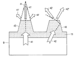
- FIG. 4 is a cross-section of a trapezoidal structure of a lenticular screen.
- FIG. 1 is a schematic view of the display device 1 and the illumination system 2 .
- the illumination system 2 comprises a light source 3 , a reflector 5 and a collimating system 7 .
- the collimation angle is about 30° to prevent grey scale inversion in the vertical direction.
- the display device 1 preferably comprises two liquid crystal display panels 20 , 22 configured next to each other and separated by a seam 24 .
- the seam 24 between the two liquid crystal display panels 22 , 24 is in the vertical direction.
- the display device 1 is provided with a lenticular screen 9 enlarging the luminance distribution in the horizontal direction due to the application of the collimated illumination system 2 .
- the liquid crystal display panels 20 and 22 comprise conventional 90 degree twisted-nematic liquid crystal cells.
- the rubbing directions for an orientation layer of the liquid crystal cell are chosen to be such that the viewing angle in the first c.q. vertical direction is symmetric about a normal to the liquid crystal display panel 20 , 22 . Consequently, the viewing angle in the horizontal direction becomes asymmetric about the normal.
- FIG. 2 is a front view of display device 1 comprising two liquid crystal display panels 20 , 22 .
- the black mask 26 covering the display panels 20 , 22 is represented by the periodical line structure 28 .
- the periodical line structure 28 matches with the pitch of the picture elements in the second, c.q. horizontal direction.
- the application of the collimated illumination system 2 as is shown in FIG. 1 prevents also light entering the seam area. If the display device 1 has only a single seam 24 in the vertical direction, the requirements imposed on the collimating illumination system 7 in this direction may be less stringent.
- the widest collimating angle is chosen to provide the largest viewing angle at which no grey scale inversion occurs in the vertical direction. This angle can be deduced from FIG. 3 b and FIG. 3 d.
- FIG. 3 shows a simulated luminance versus viewing angle characteristics at 5 different grey levels in different directions of a liquid crystal display panel.
- FIG. 3 a and FIG. 3 b show the respective luminance versus viewing angle characteristics in the horizontal and the vertical direction for a liquid crystal display panel optically coupled with a Wide Viewing Angle foil laminated on the liquid crystal display panels.
- FIG. 3 c and FIG. 3 d show the respective luminance versus viewing angle characteristics in the horizontal and the vertical direction for a liquid crystal display panel without such Wide Viewing Angle foils.
- the nominal grey levels chosen are 0, 0.25, 0.5, 0.75 and 1, respectively.
- the respective curves 41 - 45 represent the luminance versus viewing angle characteristics. For these Figures, it is assumed that the light distribution is isotropic. In FIGS. 3 a to 3 d, the angles for which the curves 41 to 45 cross each other indicate the start of grey inversion.
- the lenticular screen 9 enlarges the limited light distribution.
- the wide collimating angle in the display device 1 gives rise to an asymmetric viewing angle in the horizontal direction, see FIG. 3 c and FIG. 3 d.
- the lenticular screen 9 has a trapezoidal structure 11 .
- FIG. 4 shows a portion of a lenticular screen 9 having a trapezoidal structure 11 .
- this trapezoidal structure 11 light rays 42 bouncing at the slanted sides 43 of the trapezoids are reflected by means of total reflection, and rays traversing the liquid crystal panels 20 , 22 at different positive and negative horizontal angles are mixed. In this way, the asymmetry of the viewing angle in the horizontal direction can be averaged and is therefore reduced.
- the desired horizontal spread and the required viewing angle symmetry in the horizontal direction determine the apex angle ⁇ of the trapezoids 43 . In practice, this apex angle is 20°.
- a larger angle ⁇ possibly in combination with a deeper trapezoidal structure, provides more correction and a larger horizontal spread.
- a smaller angle ⁇ provides less correction and a smaller horizontal spread.
- the lenticular screen 9 is provided with a bulk diffuser dispersed in the host material of the trapezoidal structure 11 for widening the luminance distribution in the vertical direction.
- the refractive index of the bulk diffuser deviates from the refractive index of the host material by about 0.1 so as to reduce back-scattering of incident light.
- the refractive index of the bulk diffuser is 1.520 and the refractive index of the host material is 1.495.
- the bulk diffuser scatters a light ray 41 incident normal to the lenticular screen in light rays 41 ′ as is shown in trapezoidal structure 11 .
- a light ray 42 incident oblique to the normal at an angle larger than the Brewster angle is reflected and scattered by the bulk diffuser in light rays 42 ′ and 42 ′′.
Abstract
The invention relates to a display device comprising LC panels arranged next to each other. To reduce the visibility of a seam between two adjacent LC panels and to avoid grey scale inversion, collimated light is applied. A lenticular foil is used to enlarge the viewing angle in the horizontal direction. If the seam is only present in a vertical direction, the widest viewing angle in the vertical direction should be chosen. This choice leads to an asymmetric viewing angle in a horizontal direction. To reduce the asymmetry in the horizontal viewing angle, the lenticulars of the screen have a trapezoidal shape. The apex angle depends on the desired spread and viewing angle symmetry in the horizontal direction.
Description
The invention relates to a display device as defined in the precharacterizing part of claim 1.
The invention further relates to a lenticular screen for use in a display device.
The display device is used for displaying television and graphic images.
The display device may comprise two or more liquid crystal display panels which are arranged next to each other for enlarging the physical size of the display, without enlarging the size of the display panels. In this way, a relatively cheap display is obtained. A seam is present at the neighboring sides of the liquid crystal display panels. In order to reduce the visibility of the seam between the liquid crystal display panels, it is necessary to prevent light entering the seam area. This is achieved by a black mask, which is periodical across the entire display, and by the application of collimated light distribution. The collimated light distribution requires a lenticular screen which is optically coupled to the liquid crystal display panels for enlarging the luminance distribution of the display after the light has passed through the liquid crystal display panels.
The display device may have such a configuration of liquid crystal display panels that only vertical seams are present. Consequently, also the black mask has only a periodical vertical structure. In this type of display device, the requirements of the collimated light source in the vertical direction are less stringent and the lumen output or the luminance at the front of the display device can be increased. In order to obtain an increased lumen output of the display device, the widest possible collimating angle is chosen for which no grey scale inversion occurs in the vertical direction of the liquid crystal display device.
A disadvantage of the present display device is that this collimating angle will give rise to a viewing asymmetry in the horizontal direction.
It is an object of the invention to provide a display device with a reduced viewing angle asymmetry in the horizontal direction. This object is achieved by a display device according to the invention as defined in claim 1. The trapezoidal structure of the lenticular screen of the display device according to the invention mixes light rays traversing the liquid crystal panels at positive and negative angles about the normal in the second direction. The light rays coming from the different positive and negative angles will be totally reflected at the slanted sides of the trapezoidal structure, and the asymmetry of the luminance in the viewing angle in the second direction is averaged and will be reduced. The known lenticular screens only enlarge the luminance distribution but do not mix the light incident at oblique angles with respect to the normal of the lenticular screen, so that the asymmetry in the second direction is not reduced.
Advantageous embodiments of the display device according to the invention are defined in the dependent claims.
These and other aspects of the invention are apparent from and will be elucidated with reference to the embodiments described hereinafter.
In the drawing:
FIG. 1 shows a liquid crystal display device and a collimating illumination system,
FIG. 2 is a front view of a display device comprising two liquid crystal cells,
FIG. 3 shows several graphs of simulated luminance versus viewing angle at different grey levels in vertical and horizontal directions for a twisted-nematic liquid crystal display panel and
FIG. 4 is a cross-section of a trapezoidal structure of a lenticular screen.
FIG. 1 is a schematic view of the display device 1 and the illumination system 2. The illumination system 2 comprises a light source 3, a reflector 5 and a collimating system 7. Preferably, the collimation angle is about 30° to prevent grey scale inversion in the vertical direction. Furthermore, the display device 1 preferably comprises two liquid crystal display panels 20,22 configured next to each other and separated by a seam 24. In this example, the seam 24 between the two liquid crystal display panels 22,24 is in the vertical direction. Furthermore, the display device 1 is provided with a lenticular screen 9 enlarging the luminance distribution in the horizontal direction due to the application of the collimated illumination system 2.
The liquid crystal display panels 20 and 22 comprise conventional 90 degree twisted-nematic liquid crystal cells. The rubbing directions for an orientation layer of the liquid crystal cell are chosen to be such that the viewing angle in the first c.q. vertical direction is symmetric about a normal to the liquid crystal display panel 20,22. Consequently, the viewing angle in the horizontal direction becomes asymmetric about the normal. In order to reduce the visibility of the seam 24, it is necessary to prevent light entering the seam area. This can be achieved by providing the liquid crystal display panels 20,22 with a black mask 26 with a periodical line structure in the vertical direction.
FIG. 2 is a front view of display device 1 comprising two liquid crystal display panels 20,22. The black mask 26 covering the display panels 20,22 is represented by the periodical line structure 28. The periodical line structure 28 matches with the pitch of the picture elements in the second, c.q. horizontal direction. Furthermore, the application of the collimated illumination system 2 as is shown in FIG. 1 prevents also light entering the seam area. If the display device 1 has only a single seam 24 in the vertical direction, the requirements imposed on the collimating illumination system 7 in this direction may be less stringent. In order to increase the light output or the front luminance of the display device 1, the widest collimating angle is chosen to provide the largest viewing angle at which no grey scale inversion occurs in the vertical direction. This angle can be deduced from FIG. 3b and FIG. 3d.
FIG. 3 shows a simulated luminance versus viewing angle characteristics at 5 different grey levels in different directions of a liquid crystal display panel. FIG. 3a and FIG. 3b show the respective luminance versus viewing angle characteristics in the horizontal and the vertical direction for a liquid crystal display panel optically coupled with a Wide Viewing Angle foil laminated on the liquid crystal display panels. FIG. 3c and FIG. 3d show the respective luminance versus viewing angle characteristics in the horizontal and the vertical direction for a liquid crystal display panel without such Wide Viewing Angle foils. The nominal grey levels chosen are 0, 0.25, 0.5, 0.75 and 1, respectively. The respective curves 41-45 represent the luminance versus viewing angle characteristics. For these Figures, it is assumed that the light distribution is isotropic. In FIGS. 3a to 3 d, the angles for which the curves 41 to 45 cross each other indicate the start of grey inversion.
As described hereinbefore, the lenticular screen 9 enlarges the limited light distribution. However, the wide collimating angle in the display device 1 gives rise to an asymmetric viewing angle in the horizontal direction, see FIG. 3c and FIG. 3d. In order to reduce the asymmetry in the vie wing direction in the horizontal direction, the lenticular screen 9 has a trapezoidal structure 11.
FIG. 4 shows a portion of a lenticular screen 9 having a trapezoidal structure 11. In this trapezoidal structure 11, light rays 42 bouncing at the slanted sides 43 of the trapezoids are reflected by means of total reflection, and rays traversing the liquid crystal panels 20,22 at different positive and negative horizontal angles are mixed. In this way, the asymmetry of the viewing angle in the horizontal direction can be averaged and is therefore reduced. The desired horizontal spread and the required viewing angle symmetry in the horizontal direction determine the apex angle α of the trapezoids 43. In practice, this apex angle is 20°. A larger angle α, possibly in combination with a deeper trapezoidal structure, provides more correction and a larger horizontal spread. A smaller angle α provides less correction and a smaller horizontal spread.
Furthermore, the lenticular screen 9 is provided with a bulk diffuser dispersed in the host material of the trapezoidal structure 11 for widening the luminance distribution in the vertical direction. Preferably, the refractive index of the bulk diffuser deviates from the refractive index of the host material by about 0.1 so as to reduce back-scattering of incident light. In this example, the refractive index of the bulk diffuser is 1.520 and the refractive index of the host material is 1.495. The bulk diffuser scatters a light ray 41 incident normal to the lenticular screen in light rays 41′ as is shown in trapezoidal structure 11. A light ray 42 incident oblique to the normal at an angle larger than the Brewster angle is reflected and scattered by the bulk diffuser in light rays 42′ and 42″.
It will be evident that many variations are possible within the framework of the invention.
Claims (8)
1. A display device comprising:
a light source,
a liquid crystal display panel,
a collimating system for collimating light from the light source on the liquid crystal display panel a predetermined collimating angle, and
a lenticular screen optically coupled to the liquid crystal display panel at the side of a viewer,
lenticulars of the lenticular screen being directed in a first direction for enlarging luminance distribution in a second direction,
characterized in that
the lenticulars:
have a trapezoidal shape with two substantially parallel sides and at least one slanted side that forms an apex angle of the trapezoidal shape, and are arranged such that the light from the light source enters via one side of the two parallel sides and exits the other side of the two parallel sides, and
the apex angle is configured so that light from the light source is reflected from the at least one slanted side to also exit the other side of the two parallel sides, thereby reducing asymmetry of the luminance distribution.
2. A display device as claimed in claim 1 , characterized in that the apex angle of the trapezoid is dependent on a desired horizontal spread and a desired viewing angle symmetry in the second direction.
3. A display device as claimed in claim 1 , characterized in that the lenticular screen comprises a host material and a bulk diffusing material dispersed in the host material.
4. A display device as claimed in claim 3 , characterized in that the bulk diffusing material has a first refractive index which is different from a second refractive index of the host material.
5. A display device as claimed in claim 1 , characterized in that the liquid crystal display panels are provided with a front polarizer at the side of the lenticular screen, and the lenticular screen is optically coupled to the front polarizer by means of lamination.
6. A display device as claimed in claim 1 , wherein the liquid crystal display panel comprises a plurality of liquid crystal display panel segments configured next to each other in the second direction and having a seam in the first direction.
7. A display device as claimed in claim 6 characterized in that the liquid crystal display panel is provided with a black mask extending across the plurality of liquid crystal display panel segments, the black mask having a periodical structure corresponding to a pitch of a picture element of the liquid crystal display panel.
8. A lenticular screen for use in a display device as claimed in claim 1 .
Applications Claiming Priority (3)
| Application Number | Priority Date | Filing Date | Title |
|---|---|---|---|
| EP00204437 | 2000-12-12 | ||
| EP00204437 | 2000-12-12 | ||
| EP00204437.8 | 2000-12-12 |
Publications (2)
| Publication Number | Publication Date |
|---|---|
| US20020093607A1 US20020093607A1 (en) | 2002-07-18 |
| US6667786B2 true US6667786B2 (en) | 2003-12-23 |
Family
ID=8172413
Family Applications (1)
| Application Number | Title | Priority Date | Filing Date |
|---|---|---|---|
| US10/020,020 Expired - Fee Related US6667786B2 (en) | 2000-12-12 | 2001-12-07 | Display device and lenticular screen |
Country Status (6)
| Country | Link |
|---|---|
| US (1) | US6667786B2 (en) |
| EP (1) | EP1254397A1 (en) |
| JP (1) | JP2004516499A (en) |
| KR (1) | KR20020079834A (en) |
| CN (1) | CN1401095A (en) |
| WO (1) | WO2002048791A1 (en) |
Cited By (3)
| Publication number | Priority date | Publication date | Assignee | Title |
|---|---|---|---|---|
| US7046906B1 (en) * | 2005-01-21 | 2006-05-16 | Inventec Corporation | Light guide pillar |
| US20060176558A1 (en) * | 2005-02-04 | 2006-08-10 | James Plant | Polarization filter utilizing Brewster's angle |
| US20180164597A1 (en) * | 2016-12-14 | 2018-06-14 | Pure Depth Limited | Fixed depth display for vehicle instrument panel |
Families Citing this family (9)
| Publication number | Priority date | Publication date | Assignee | Title |
|---|---|---|---|---|
| FR2849932B1 (en) * | 2003-01-15 | 2005-02-18 | Saint Gobain | RETROPROJECTION AND / OR PROJECTION SCREEN |
| KR101279114B1 (en) * | 2005-10-13 | 2013-06-26 | 엘지디스플레이 주식회사 | Liquid crystal display device |
| TWI348070B (en) * | 2007-12-31 | 2011-09-01 | Ind Tech Res Inst | Bistable projection screen |
| JP5448981B2 (en) | 2009-04-08 | 2014-03-19 | 株式会社半導体エネルギー研究所 | Driving method of liquid crystal display device |
| KR101680770B1 (en) | 2010-07-09 | 2016-11-29 | 삼성전자주식회사 | Back light unit and display apparatus employing the same |
| US10983388B2 (en) | 2017-03-15 | 2021-04-20 | Lg Display Co., Ltd. | Display device |
| KR102329112B1 (en) | 2017-06-21 | 2021-11-18 | 레이아 인코포레이티드 | Microprism multi-beam device backlight and multi-view display using same |
| KR102410084B1 (en) * | 2017-07-04 | 2022-06-20 | 삼성디스플레이 주식회사 | Display apparatus and fabrication method thereof |
| KR20230099805A (en) | 2021-12-28 | 2023-07-05 | 허준영 | Wake-up alarm setting and sleep induction device using EEG analysis |
Citations (4)
| Publication number | Priority date | Publication date | Assignee | Title |
|---|---|---|---|---|
| US5462700A (en) | 1993-11-08 | 1995-10-31 | Alliedsignal Inc. | Process for making an array of tapered photopolymerized waveguides |
| US5521725A (en) * | 1993-11-05 | 1996-05-28 | Alliedsignal Inc. | Illumination system employing an array of microprisms |
| US5751387A (en) * | 1995-07-28 | 1998-05-12 | Fujitsu Limited | Fresnel lens and liquid crystal display device |
| US6163351A (en) * | 1998-06-08 | 2000-12-19 | Sharp Kabushiki Kaisha | Backlight for liquid crystal display apparatus and liquid crystal display apparatus incorporating the same |
Family Cites Families (2)
| Publication number | Priority date | Publication date | Assignee | Title |
|---|---|---|---|---|
| DK687288A (en) * | 1988-12-09 | 1990-06-10 | Dainippon Printing Co Ltd | A rear projection screen |
| KR0168879B1 (en) * | 1992-12-25 | 1999-04-15 | 기따지마 요시또시 | Renticular lens, surface light source and liquid crystal display apparatus |
-
2001
- 2001-11-26 JP JP2002550440A patent/JP2004516499A/en not_active Withdrawn
- 2001-11-26 CN CN01804892A patent/CN1401095A/en active Pending
- 2001-11-26 EP EP01270805A patent/EP1254397A1/en not_active Withdrawn
- 2001-11-26 KR KR1020027010150A patent/KR20020079834A/en not_active Application Discontinuation
- 2001-11-26 WO PCT/EP2001/013820 patent/WO2002048791A1/en not_active Application Discontinuation
- 2001-12-07 US US10/020,020 patent/US6667786B2/en not_active Expired - Fee Related
Patent Citations (4)
| Publication number | Priority date | Publication date | Assignee | Title |
|---|---|---|---|---|
| US5521725A (en) * | 1993-11-05 | 1996-05-28 | Alliedsignal Inc. | Illumination system employing an array of microprisms |
| US5462700A (en) | 1993-11-08 | 1995-10-31 | Alliedsignal Inc. | Process for making an array of tapered photopolymerized waveguides |
| US5751387A (en) * | 1995-07-28 | 1998-05-12 | Fujitsu Limited | Fresnel lens and liquid crystal display device |
| US6163351A (en) * | 1998-06-08 | 2000-12-19 | Sharp Kabushiki Kaisha | Backlight for liquid crystal display apparatus and liquid crystal display apparatus incorporating the same |
Cited By (7)
| Publication number | Priority date | Publication date | Assignee | Title |
|---|---|---|---|---|
| US7046906B1 (en) * | 2005-01-21 | 2006-05-16 | Inventec Corporation | Light guide pillar |
| US20060176558A1 (en) * | 2005-02-04 | 2006-08-10 | James Plant | Polarization filter utilizing Brewster's angle |
| US7619817B2 (en) * | 2005-02-04 | 2009-11-17 | James Plant | Polarization filter utilizing Brewster's angle |
| US20100033815A1 (en) * | 2005-02-04 | 2010-02-11 | James Plant | Polarization filter utilizing brewster's angle |
| US8000007B2 (en) | 2005-02-04 | 2011-08-16 | James Plant | Polarization filter utilizing Brewster's angle |
| US20180164597A1 (en) * | 2016-12-14 | 2018-06-14 | Pure Depth Limited | Fixed depth display for vehicle instrument panel |
| US11150488B2 (en) * | 2016-12-14 | 2021-10-19 | Pure Depth Limited | Fixed depth display for vehicle instrument panel |
Also Published As
| Publication number | Publication date |
|---|---|
| WO2002048791A1 (en) | 2002-06-20 |
| JP2004516499A (en) | 2004-06-03 |
| EP1254397A1 (en) | 2002-11-06 |
| US20020093607A1 (en) | 2002-07-18 |
| KR20020079834A (en) | 2002-10-19 |
| CN1401095A (en) | 2003-03-05 |
Similar Documents
| Publication | Publication Date | Title |
|---|---|---|
| US6667786B2 (en) | Display device and lenticular screen | |
| US4911529A (en) | Front projection screen | |
| JP5332138B2 (en) | Display system | |
| WO1996023245A1 (en) | Liquid crystal display device | |
| EP0732615B1 (en) | Rear projection image display device | |
| JPH03213840A (en) | Rear projection type screen and rear projection type image display device using it | |
| JPWO2017221528A1 (en) | Transparent screen and image display system | |
| US7675679B2 (en) | Image display device and Fresnel lens sheet used therefor | |
| JPH11338056A (en) | Video display device | |
| CN207966376U (en) | A kind of microarray flat-panel display device and flat panel display systems | |
| JP5005193B2 (en) | Prism sheet, projector screen and multi-screen display device | |
| JP2000137294A (en) | Visual field control sheet, back surface projection type screen and back surface projection type display | |
| JP2888297B2 (en) | projector | |
| EP0471478A2 (en) | Large screen display apparatus | |
| US5264941A (en) | Large screen display apparatus utilizing a transparent plate to display an image over an entire surface of a diffusing surface | |
| JP3899717B2 (en) | Liquid crystal display | |
| JP2011027764A (en) | Light diffusing member and liquid crystal display device | |
| JPH1138510A (en) | Projector screen | |
| KR100649556B1 (en) | Screen with improved view angle property and projection display system having the same | |
| JPH06202233A (en) | Screen for projection television | |
| JPH08220345A (en) | Back light structure of liquid crystal display device | |
| JPH09179113A (en) | Liquid crystal display device | |
| JPH0519347A (en) | Projection type image display device | |
| JP3682180B2 (en) | Projection type screen | |
| JP2007328287A (en) | Display device |
Legal Events
| Date | Code | Title | Description |
|---|---|---|---|
| AS | Assignment |
Owner name: KONINKLIJKE PHILIPS ELECTRONICS N.V., NETHERLANDS Free format text: ASSIGNMENT OF ASSIGNORS INTEREST;ASSIGNORS:VAN DE VEN, JOHANNES CORNELIS;WEEGELS, LEO MARIE;REEL/FRAME:012809/0443;SIGNING DATES FROM 20020117 TO 20020207 |
|
| REMI | Maintenance fee reminder mailed | ||
| LAPS | Lapse for failure to pay maintenance fees | ||
| STCH | Information on status: patent discontinuation |
Free format text: PATENT EXPIRED DUE TO NONPAYMENT OF MAINTENANCE FEES UNDER 37 CFR 1.362 |
|
| FP | Lapsed due to failure to pay maintenance fee |
Effective date: 20071223 |