JP5448981B2 - Driving method of liquid crystal display device - Google Patents
Driving method of liquid crystal display device Download PDFInfo
- Publication number
- JP5448981B2 JP5448981B2 JP2010085690A JP2010085690A JP5448981B2 JP 5448981 B2 JP5448981 B2 JP 5448981B2 JP 2010085690 A JP2010085690 A JP 2010085690A JP 2010085690 A JP2010085690 A JP 2010085690A JP 5448981 B2 JP5448981 B2 JP 5448981B2
- Authority
- JP
- Japan
- Prior art keywords
- image
- processing
- resolution
- super
- circuit
- Prior art date
- Legal status (The legal status is an assumption and is not a legal conclusion. Google has not performed a legal analysis and makes no representation as to the accuracy of the status listed.)
- Active
Links
- 238000000034 method Methods 0.000 title claims description 455
- 239000004973 liquid crystal related substance Substances 0.000 title claims description 159
- 238000012545 processing Methods 0.000 claims description 495
- 230000008569 process Effects 0.000 claims description 317
- 239000010410 layer Substances 0.000 description 239
- 239000000758 substrate Substances 0.000 description 133
- 239000004065 semiconductor Substances 0.000 description 96
- 230000006870 function Effects 0.000 description 88
- 239000003990 capacitor Substances 0.000 description 54
- 238000004519 manufacturing process Methods 0.000 description 48
- 238000005192 partition Methods 0.000 description 48
- 239000010408 film Substances 0.000 description 47
- 238000012937 correction Methods 0.000 description 45
- 230000033001 locomotion Effects 0.000 description 45
- 230000008859 change Effects 0.000 description 39
- 238000002834 transmittance Methods 0.000 description 39
- 206010047571 Visual impairment Diseases 0.000 description 32
- 230000004044 response Effects 0.000 description 31
- XUIMIQQOPSSXEZ-UHFFFAOYSA-N Silicon Chemical compound [Si] XUIMIQQOPSSXEZ-UHFFFAOYSA-N 0.000 description 29
- 229910052710 silicon Inorganic materials 0.000 description 29
- 239000010703 silicon Substances 0.000 description 29
- 239000000463 material Substances 0.000 description 27
- 238000010586 diagram Methods 0.000 description 23
- 238000006243 chemical reaction Methods 0.000 description 22
- 125000006850 spacer group Chemical group 0.000 description 18
- 239000013598 vector Substances 0.000 description 18
- 230000008901 benefit Effects 0.000 description 15
- 238000009792 diffusion process Methods 0.000 description 15
- 239000011159 matrix material Substances 0.000 description 15
- 229910052782 aluminium Inorganic materials 0.000 description 14
- XAGFODPZIPBFFR-UHFFFAOYSA-N aluminium Chemical compound [Al] XAGFODPZIPBFFR-UHFFFAOYSA-N 0.000 description 14
- 239000013078 crystal Substances 0.000 description 14
- 239000011521 glass Substances 0.000 description 14
- 238000010191 image analysis Methods 0.000 description 14
- 239000003086 colorant Substances 0.000 description 12
- 150000001875 compounds Chemical class 0.000 description 12
- 239000012535 impurity Substances 0.000 description 12
- 230000015654 memory Effects 0.000 description 12
- 229910052751 metal Inorganic materials 0.000 description 11
- 239000002184 metal Substances 0.000 description 11
- OKTJSMMVPCPJKN-UHFFFAOYSA-N Carbon Chemical compound [C] OKTJSMMVPCPJKN-UHFFFAOYSA-N 0.000 description 10
- 230000014759 maintenance of location Effects 0.000 description 10
- PXHVJJICTQNCMI-UHFFFAOYSA-N Nickel Chemical compound [Ni] PXHVJJICTQNCMI-UHFFFAOYSA-N 0.000 description 9
- 238000005516 engineering process Methods 0.000 description 9
- 230000006872 improvement Effects 0.000 description 9
- 230000003287 optical effect Effects 0.000 description 9
- 229920003023 plastic Polymers 0.000 description 9
- 239000004033 plastic Substances 0.000 description 9
- 239000004983 Polymer Dispersed Liquid Crystal Substances 0.000 description 8
- -1 a-InGaZnO Inorganic materials 0.000 description 8
- 230000000694 effects Effects 0.000 description 8
- 230000005684 electric field Effects 0.000 description 8
- 239000005262 ferroelectric liquid crystals (FLCs) Substances 0.000 description 8
- 238000003672 processing method Methods 0.000 description 8
- VYPSYNLAJGMNEJ-UHFFFAOYSA-N silicon dioxide Inorganic materials O=[Si]=O VYPSYNLAJGMNEJ-UHFFFAOYSA-N 0.000 description 8
- 239000010936 titanium Substances 0.000 description 8
- 229910052581 Si3N4 Inorganic materials 0.000 description 7
- RTAQQCXQSZGOHL-UHFFFAOYSA-N Titanium Chemical compound [Ti] RTAQQCXQSZGOHL-UHFFFAOYSA-N 0.000 description 7
- XLOMVQKBTHCTTD-UHFFFAOYSA-N Zinc monoxide Chemical compound [Zn]=O XLOMVQKBTHCTTD-UHFFFAOYSA-N 0.000 description 7
- 239000002041 carbon nanotube Substances 0.000 description 7
- 229910021393 carbon nanotube Inorganic materials 0.000 description 7
- 230000006866 deterioration Effects 0.000 description 7
- HQVNEWCFYHHQES-UHFFFAOYSA-N silicon nitride Chemical compound N12[Si]34N5[Si]62N3[Si]51N64 HQVNEWCFYHHQES-UHFFFAOYSA-N 0.000 description 7
- 229910052719 titanium Inorganic materials 0.000 description 7
- IJGRMHOSHXDMSA-UHFFFAOYSA-N Atomic nitrogen Chemical compound N#N IJGRMHOSHXDMSA-UHFFFAOYSA-N 0.000 description 6
- ZOKXTWBITQBERF-UHFFFAOYSA-N Molybdenum Chemical compound [Mo] ZOKXTWBITQBERF-UHFFFAOYSA-N 0.000 description 6
- 230000005540 biological transmission Effects 0.000 description 6
- 238000001962 electrophoresis Methods 0.000 description 6
- 229910052750 molybdenum Inorganic materials 0.000 description 6
- 239000011733 molybdenum Substances 0.000 description 6
- 229910021420 polycrystalline silicon Inorganic materials 0.000 description 6
- 229920000728 polyester Polymers 0.000 description 6
- 239000005020 polyethylene terephthalate Substances 0.000 description 6
- 229920000139 polyethylene terephthalate Polymers 0.000 description 6
- 230000000750 progressive effect Effects 0.000 description 6
- 230000009467 reduction Effects 0.000 description 6
- LIVNPJMFVYWSIS-UHFFFAOYSA-N silicon monoxide Chemical compound [Si-]#[O+] LIVNPJMFVYWSIS-UHFFFAOYSA-N 0.000 description 6
- 229910052814 silicon oxide Inorganic materials 0.000 description 6
- 239000002356 single layer Substances 0.000 description 6
- 238000003860 storage Methods 0.000 description 6
- 239000010409 thin film Substances 0.000 description 6
- WFKWXMTUELFFGS-UHFFFAOYSA-N tungsten Chemical compound [W] WFKWXMTUELFFGS-UHFFFAOYSA-N 0.000 description 6
- 229910052721 tungsten Inorganic materials 0.000 description 6
- 239000010937 tungsten Substances 0.000 description 6
- OAICVXFJPJFONN-UHFFFAOYSA-N Phosphorus Chemical compound [P] OAICVXFJPJFONN-UHFFFAOYSA-N 0.000 description 5
- NIXOWILDQLNWCW-UHFFFAOYSA-N acrylic acid group Chemical group C(C=C)(=O)O NIXOWILDQLNWCW-UHFFFAOYSA-N 0.000 description 5
- 239000000956 alloy Substances 0.000 description 5
- 238000004364 calculation method Methods 0.000 description 5
- 238000003384 imaging method Methods 0.000 description 5
- 239000002071 nanotube Substances 0.000 description 5
- 230000002093 peripheral effect Effects 0.000 description 5
- 239000004575 stone Substances 0.000 description 5
- 239000000126 substance Substances 0.000 description 5
- 239000004986 Cholesteric liquid crystals (ChLC) Substances 0.000 description 4
- 229910052779 Neodymium Inorganic materials 0.000 description 4
- 229910021417 amorphous silicon Inorganic materials 0.000 description 4
- 238000004458 analytical method Methods 0.000 description 4
- 238000001816 cooling Methods 0.000 description 4
- 239000010949 copper Substances 0.000 description 4
- 230000003111 delayed effect Effects 0.000 description 4
- 238000001514 detection method Methods 0.000 description 4
- 239000011888 foil Substances 0.000 description 4
- 229910021424 microcrystalline silicon Inorganic materials 0.000 description 4
- QEFYFXOXNSNQGX-UHFFFAOYSA-N neodymium atom Chemical compound [Nd] QEFYFXOXNSNQGX-UHFFFAOYSA-N 0.000 description 4
- 229910052759 nickel Inorganic materials 0.000 description 4
- 239000002245 particle Substances 0.000 description 4
- 229910052684 Cerium Inorganic materials 0.000 description 3
- RYGMFSIKBFXOCR-UHFFFAOYSA-N Copper Chemical compound [Cu] RYGMFSIKBFXOCR-UHFFFAOYSA-N 0.000 description 3
- 238000007476 Maximum Likelihood Methods 0.000 description 3
- 239000004988 Nematic liquid crystal Substances 0.000 description 3
- KDLHZDBZIXYQEI-UHFFFAOYSA-N Palladium Chemical compound [Pd] KDLHZDBZIXYQEI-UHFFFAOYSA-N 0.000 description 3
- 239000004952 Polyamide Substances 0.000 description 3
- 239000004642 Polyimide Substances 0.000 description 3
- BQCADISMDOOEFD-UHFFFAOYSA-N Silver Chemical compound [Ag] BQCADISMDOOEFD-UHFFFAOYSA-N 0.000 description 3
- 230000009471 action Effects 0.000 description 3
- QVGXLLKOCUKJST-UHFFFAOYSA-N atomic oxygen Chemical compound [O] QVGXLLKOCUKJST-UHFFFAOYSA-N 0.000 description 3
- FFBHFFJDDLITSX-UHFFFAOYSA-N benzyl N-[2-hydroxy-4-(3-oxomorpholin-4-yl)phenyl]carbamate Chemical compound OC1=C(NC(=O)OCC2=CC=CC=C2)C=CC(=C1)N1CCOCC1=O FFBHFFJDDLITSX-UHFFFAOYSA-N 0.000 description 3
- 229910052799 carbon Inorganic materials 0.000 description 3
- 239000003054 catalyst Substances 0.000 description 3
- GWXLDORMOJMVQZ-UHFFFAOYSA-N cerium Chemical compound [Ce] GWXLDORMOJMVQZ-UHFFFAOYSA-N 0.000 description 3
- 238000004891 communication Methods 0.000 description 3
- 229910052802 copper Inorganic materials 0.000 description 3
- 238000011156 evaluation Methods 0.000 description 3
- 239000007789 gas Substances 0.000 description 3
- 230000020169 heat generation Effects 0.000 description 3
- 239000003779 heat-resistant material Substances 0.000 description 3
- AMGQUBHHOARCQH-UHFFFAOYSA-N indium;oxotin Chemical compound [In].[Sn]=O AMGQUBHHOARCQH-UHFFFAOYSA-N 0.000 description 3
- 238000002347 injection Methods 0.000 description 3
- 239000007924 injection Substances 0.000 description 3
- 239000012212 insulator Substances 0.000 description 3
- 239000013081 microcrystal Substances 0.000 description 3
- 229910021421 monocrystalline silicon Inorganic materials 0.000 description 3
- 229910052757 nitrogen Inorganic materials 0.000 description 3
- 239000011368 organic material Substances 0.000 description 3
- 229910052760 oxygen Inorganic materials 0.000 description 3
- 239000001301 oxygen Substances 0.000 description 3
- 229910052698 phosphorus Inorganic materials 0.000 description 3
- 239000011574 phosphorus Substances 0.000 description 3
- BASFCYQUMIYNBI-UHFFFAOYSA-N platinum Chemical compound [Pt] BASFCYQUMIYNBI-UHFFFAOYSA-N 0.000 description 3
- 229920002647 polyamide Polymers 0.000 description 3
- 229920001721 polyimide Polymers 0.000 description 3
- 229910052709 silver Inorganic materials 0.000 description 3
- 239000004332 silver Substances 0.000 description 3
- 239000010935 stainless steel Substances 0.000 description 3
- 229910001220 stainless steel Inorganic materials 0.000 description 3
- 230000002123 temporal effect Effects 0.000 description 3
- 239000011787 zinc oxide Substances 0.000 description 3
- 238000012935 Averaging Methods 0.000 description 2
- ZOXJGFHDIHLPTG-UHFFFAOYSA-N Boron Chemical compound [B] ZOXJGFHDIHLPTG-UHFFFAOYSA-N 0.000 description 2
- 239000004985 Discotic Liquid Crystal Substance Substances 0.000 description 2
- 229910001218 Gallium arsenide Inorganic materials 0.000 description 2
- 239000005264 High molar mass liquid crystal Substances 0.000 description 2
- 241000234295 Musa Species 0.000 description 2
- 235000018290 Musa x paradisiaca Nutrition 0.000 description 2
- 229910000583 Nd alloy Inorganic materials 0.000 description 2
- 229920001609 Poly(3,4-ethylenedioxythiophene) Polymers 0.000 description 2
- 229920012266 Poly(ether sulfone) PES Polymers 0.000 description 2
- 239000004743 Polypropylene Substances 0.000 description 2
- 229910000577 Silicon-germanium Inorganic materials 0.000 description 2
- 239000004990 Smectic liquid crystal Substances 0.000 description 2
- 239000004974 Thermotropic liquid crystal Substances 0.000 description 2
- BZHJMEDXRYGGRV-UHFFFAOYSA-N Vinyl chloride Chemical compound ClC=C BZHJMEDXRYGGRV-UHFFFAOYSA-N 0.000 description 2
- ZGUQGPFMMTZGBQ-UHFFFAOYSA-N [Al].[Al].[Zr] Chemical compound [Al].[Al].[Zr] ZGUQGPFMMTZGBQ-UHFFFAOYSA-N 0.000 description 2
- 229910045601 alloy Inorganic materials 0.000 description 2
- 239000005407 aluminoborosilicate glass Substances 0.000 description 2
- HIPVTVNIGFETDW-UHFFFAOYSA-N aluminum cerium Chemical compound [Al].[Ce] HIPVTVNIGFETDW-UHFFFAOYSA-N 0.000 description 2
- UBSJOWMHLJZVDJ-UHFFFAOYSA-N aluminum neodymium Chemical compound [Al].[Nd] UBSJOWMHLJZVDJ-UHFFFAOYSA-N 0.000 description 2
- 238000013459 approach Methods 0.000 description 2
- 229910052788 barium Inorganic materials 0.000 description 2
- DSAJWYNOEDNPEQ-UHFFFAOYSA-N barium atom Chemical compound [Ba] DSAJWYNOEDNPEQ-UHFFFAOYSA-N 0.000 description 2
- 230000015572 biosynthetic process Effects 0.000 description 2
- 229910052796 boron Inorganic materials 0.000 description 2
- 239000005388 borosilicate glass Substances 0.000 description 2
- 238000004422 calculation algorithm Methods 0.000 description 2
- 230000015556 catabolic process Effects 0.000 description 2
- 230000001413 cellular effect Effects 0.000 description 2
- 239000011651 chromium Substances 0.000 description 2
- 238000013500 data storage Methods 0.000 description 2
- 230000007547 defect Effects 0.000 description 2
- 238000006073 displacement reaction Methods 0.000 description 2
- 238000009826 distribution Methods 0.000 description 2
- 238000005401 electroluminescence Methods 0.000 description 2
- 230000002349 favourable effect Effects 0.000 description 2
- 239000000835 fiber Substances 0.000 description 2
- 239000002657 fibrous material Substances 0.000 description 2
- 239000012530 fluid Substances 0.000 description 2
- 230000007274 generation of a signal involved in cell-cell signaling Effects 0.000 description 2
- 239000010931 gold Substances 0.000 description 2
- 230000005525 hole transport Effects 0.000 description 2
- 239000007788 liquid Substances 0.000 description 2
- 239000011572 manganese Substances 0.000 description 2
- 239000003094 microcapsule Substances 0.000 description 2
- DTSBBUTWIOVIBV-UHFFFAOYSA-N molybdenum niobium Chemical compound [Nb].[Mo] DTSBBUTWIOVIBV-UHFFFAOYSA-N 0.000 description 2
- JZLMRQMUNCKZTP-UHFFFAOYSA-N molybdenum tantalum Chemical compound [Mo].[Ta] JZLMRQMUNCKZTP-UHFFFAOYSA-N 0.000 description 2
- 239000010955 niobium Substances 0.000 description 2
- 150000004767 nitrides Chemical class 0.000 description 2
- 239000005416 organic matter Substances 0.000 description 2
- 239000004417 polycarbonate Substances 0.000 description 2
- 229920000515 polycarbonate Polymers 0.000 description 2
- 239000011112 polyethylene naphthalate Substances 0.000 description 2
- 229920001155 polypropylene Polymers 0.000 description 2
- 229920002620 polyvinyl fluoride Polymers 0.000 description 2
- 239000010453 quartz Substances 0.000 description 2
- 239000005266 side chain polymer Substances 0.000 description 2
- 229910021332 silicide Inorganic materials 0.000 description 2
- FVBUAEGBCNSCDD-UHFFFAOYSA-N silicide(4-) Chemical compound [Si-4] FVBUAEGBCNSCDD-UHFFFAOYSA-N 0.000 description 2
- 229920003002 synthetic resin Polymers 0.000 description 2
- 239000000057 synthetic resin Substances 0.000 description 2
- 229910052715 tantalum Inorganic materials 0.000 description 2
- GUVRBAGPIYLISA-UHFFFAOYSA-N tantalum atom Chemical compound [Ta] GUVRBAGPIYLISA-UHFFFAOYSA-N 0.000 description 2
- 238000012546 transfer Methods 0.000 description 2
- 238000007740 vapor deposition Methods 0.000 description 2
- 125000000391 vinyl group Chemical group [H]C([*])=C([H])[H] 0.000 description 2
- 229920002554 vinyl polymer Polymers 0.000 description 2
- YVTHLONGBIQYBO-UHFFFAOYSA-N zinc indium(3+) oxygen(2-) Chemical compound [O--].[Zn++].[In+3] YVTHLONGBIQYBO-UHFFFAOYSA-N 0.000 description 2
- QTBSBXVTEAMEQO-UHFFFAOYSA-M Acetate Chemical compound CC([O-])=O QTBSBXVTEAMEQO-UHFFFAOYSA-M 0.000 description 1
- 101100392125 Caenorhabditis elegans gck-1 gene Proteins 0.000 description 1
- 244000025254 Cannabis sativa Species 0.000 description 1
- 235000012766 Cannabis sativa ssp. sativa var. sativa Nutrition 0.000 description 1
- 235000012765 Cannabis sativa ssp. sativa var. spontanea Nutrition 0.000 description 1
- 229920000298 Cellophane Polymers 0.000 description 1
- VYZAMTAEIAYCRO-UHFFFAOYSA-N Chromium Chemical compound [Cr] VYZAMTAEIAYCRO-UHFFFAOYSA-N 0.000 description 1
- 229920000742 Cotton Polymers 0.000 description 1
- 239000004593 Epoxy Substances 0.000 description 1
- 102100022887 GTP-binding nuclear protein Ran Human genes 0.000 description 1
- GYHNNYVSQQEPJS-UHFFFAOYSA-N Gallium Chemical compound [Ga] GYHNNYVSQQEPJS-UHFFFAOYSA-N 0.000 description 1
- 101000774835 Heteractis crispa PI-stichotoxin-Hcr2o Proteins 0.000 description 1
- 101000620756 Homo sapiens GTP-binding nuclear protein Ran Proteins 0.000 description 1
- XEEYBQQBJWHFJM-UHFFFAOYSA-N Iron Chemical compound [Fe] XEEYBQQBJWHFJM-UHFFFAOYSA-N 0.000 description 1
- 239000004976 Lyotropic liquid crystal Substances 0.000 description 1
- PWHULOQIROXLJO-UHFFFAOYSA-N Manganese Chemical compound [Mn] PWHULOQIROXLJO-UHFFFAOYSA-N 0.000 description 1
- 229910019015 Mg-Ag Inorganic materials 0.000 description 1
- 239000004677 Nylon Substances 0.000 description 1
- 229920001665 Poly-4-vinylphenol Polymers 0.000 description 1
- 229920000297 Rayon Polymers 0.000 description 1
- 101100393821 Saccharomyces cerevisiae (strain ATCC 204508 / S288c) GSP2 gene Proteins 0.000 description 1
- ATJFFYVFTNAWJD-UHFFFAOYSA-N Tin Chemical compound [Sn] ATJFFYVFTNAWJD-UHFFFAOYSA-N 0.000 description 1
- NRTOMJZYCJJWKI-UHFFFAOYSA-N Titanium nitride Chemical compound [Ti]#N NRTOMJZYCJJWKI-UHFFFAOYSA-N 0.000 description 1
- 208000003443 Unconsciousness Diseases 0.000 description 1
- QCWXUUIWCKQGHC-UHFFFAOYSA-N Zirconium Chemical compound [Zr] QCWXUUIWCKQGHC-UHFFFAOYSA-N 0.000 description 1
- 230000001133 acceleration Effects 0.000 description 1
- 238000009825 accumulation Methods 0.000 description 1
- 230000002411 adverse Effects 0.000 description 1
- 230000002776 aggregation Effects 0.000 description 1
- 238000004220 aggregation Methods 0.000 description 1
- UQZIWOQVLUASCR-UHFFFAOYSA-N alumane;titanium Chemical compound [AlH3].[Ti] UQZIWOQVLUASCR-UHFFFAOYSA-N 0.000 description 1
- CSDREXVUYHZDNP-UHFFFAOYSA-N alumanylidynesilicon Chemical compound [Al].[Si] CSDREXVUYHZDNP-UHFFFAOYSA-N 0.000 description 1
- JYJXGCDOQVBMQY-UHFFFAOYSA-N aluminum tungsten Chemical compound [Al].[W] JYJXGCDOQVBMQY-UHFFFAOYSA-N 0.000 description 1
- 238000000149 argon plasma sintering Methods 0.000 description 1
- 229910052785 arsenic Inorganic materials 0.000 description 1
- RQNWIZPPADIBDY-UHFFFAOYSA-N arsenic atom Chemical compound [As] RQNWIZPPADIBDY-UHFFFAOYSA-N 0.000 description 1
- GPBUGPUPKAGMDK-UHFFFAOYSA-N azanylidynemolybdenum Chemical compound [Mo]#N GPBUGPUPKAGMDK-UHFFFAOYSA-N 0.000 description 1
- 238000005452 bending Methods 0.000 description 1
- UMIVXZPTRXBADB-UHFFFAOYSA-N benzocyclobutene Chemical compound C1=CC=C2CCC2=C1 UMIVXZPTRXBADB-UHFFFAOYSA-N 0.000 description 1
- NNBFNNNWANBMTI-UHFFFAOYSA-M brilliant green Chemical compound OS([O-])(=O)=O.C1=CC(N(CC)CC)=CC=C1C(C=1C=CC=CC=1)=C1C=CC(=[N+](CC)CC)C=C1 NNBFNNNWANBMTI-UHFFFAOYSA-M 0.000 description 1
- BEQNOZDXPONEMR-UHFFFAOYSA-N cadmium;oxotin Chemical compound [Cd].[Sn]=O BEQNOZDXPONEMR-UHFFFAOYSA-N 0.000 description 1
- 235000009120 camo Nutrition 0.000 description 1
- 239000000919 ceramic Substances 0.000 description 1
- 235000005607 chanvre indien Nutrition 0.000 description 1
- 229910052804 chromium Inorganic materials 0.000 description 1
- 229910017052 cobalt Inorganic materials 0.000 description 1
- 239000010941 cobalt Substances 0.000 description 1
- GUTLYIVDDKVIGB-UHFFFAOYSA-N cobalt atom Chemical compound [Co] GUTLYIVDDKVIGB-UHFFFAOYSA-N 0.000 description 1
- 239000000306 component Substances 0.000 description 1
- 239000004020 conductor Substances 0.000 description 1
- 230000008602 contraction Effects 0.000 description 1
- 238000002425 crystallisation Methods 0.000 description 1
- 230000008025 crystallization Effects 0.000 description 1
- 230000003247 decreasing effect Effects 0.000 description 1
- 238000006731 degradation reaction Methods 0.000 description 1
- 238000011161 development Methods 0.000 description 1
- 239000010432 diamond Substances 0.000 description 1
- 229910003460 diamond Inorganic materials 0.000 description 1
- 208000037265 diseases, disorders, signs and symptoms Diseases 0.000 description 1
- KPUWHANPEXNPJT-UHFFFAOYSA-N disiloxane Chemical class [SiH3]O[SiH3] KPUWHANPEXNPJT-UHFFFAOYSA-N 0.000 description 1
- 239000006185 dispersion Substances 0.000 description 1
- 229920001971 elastomer Polymers 0.000 description 1
- 238000004070 electrodeposition Methods 0.000 description 1
- 238000005530 etching Methods 0.000 description 1
- 239000004744 fabric Substances 0.000 description 1
- 229910052733 gallium Inorganic materials 0.000 description 1
- PCHJSUWPFVWCPO-UHFFFAOYSA-N gold Chemical compound [Au] PCHJSUWPFVWCPO-UHFFFAOYSA-N 0.000 description 1
- 229910052737 gold Inorganic materials 0.000 description 1
- 238000009499 grossing Methods 0.000 description 1
- 238000010438 heat treatment Methods 0.000 description 1
- 239000011487 hemp Substances 0.000 description 1
- 238000000097 high energy electron diffraction Methods 0.000 description 1
- 238000003703 image analysis method Methods 0.000 description 1
- 229910052738 indium Inorganic materials 0.000 description 1
- APFVFJFRJDLVQX-UHFFFAOYSA-N indium atom Chemical compound [In] APFVFJFRJDLVQX-UHFFFAOYSA-N 0.000 description 1
- 229910010272 inorganic material Inorganic materials 0.000 description 1
- 239000011147 inorganic material Substances 0.000 description 1
- 238000009434 installation Methods 0.000 description 1
- 239000011229 interlayer Substances 0.000 description 1
- 230000001678 irradiating effect Effects 0.000 description 1
- 238000002955 isolation Methods 0.000 description 1
- 239000010985 leather Substances 0.000 description 1
- 230000031700 light absorption Effects 0.000 description 1
- 238000004020 luminiscence type Methods 0.000 description 1
- 230000002535 lyotropic effect Effects 0.000 description 1
- SJCKRGFTWFGHGZ-UHFFFAOYSA-N magnesium silver Chemical compound [Mg].[Ag] SJCKRGFTWFGHGZ-UHFFFAOYSA-N 0.000 description 1
- 230000005389 magnetism Effects 0.000 description 1
- 229910052748 manganese Inorganic materials 0.000 description 1
- QSHDDOUJBYECFT-UHFFFAOYSA-N mercury Chemical compound [Hg] QSHDDOUJBYECFT-UHFFFAOYSA-N 0.000 description 1
- 229910052753 mercury Inorganic materials 0.000 description 1
- MGRWKWACZDFZJT-UHFFFAOYSA-N molybdenum tungsten Chemical compound [Mo].[W] MGRWKWACZDFZJT-UHFFFAOYSA-N 0.000 description 1
- GALOTNBSUVEISR-UHFFFAOYSA-N molybdenum;silicon Chemical compound [Mo]#[Si] GALOTNBSUVEISR-UHFFFAOYSA-N 0.000 description 1
- 239000002159 nanocrystal Substances 0.000 description 1
- RUFLMLWJRZAWLJ-UHFFFAOYSA-N nickel silicide Chemical compound [Ni]=[Si]=[Ni] RUFLMLWJRZAWLJ-UHFFFAOYSA-N 0.000 description 1
- 229910021334 nickel silicide Inorganic materials 0.000 description 1
- 229910052758 niobium Inorganic materials 0.000 description 1
- GUCVJGMIXFAOAE-UHFFFAOYSA-N niobium atom Chemical compound [Nb] GUCVJGMIXFAOAE-UHFFFAOYSA-N 0.000 description 1
- 229920001778 nylon Polymers 0.000 description 1
- 238000005457 optimization Methods 0.000 description 1
- 229910052763 palladium Inorganic materials 0.000 description 1
- 238000000059 patterning Methods 0.000 description 1
- 229910052697 platinum Inorganic materials 0.000 description 1
- 229920006254 polymer film Polymers 0.000 description 1
- 229920005591 polysilicon Polymers 0.000 description 1
- 229920002635 polyurethane Polymers 0.000 description 1
- 239000004814 polyurethane Substances 0.000 description 1
- 229910021426 porous silicon Inorganic materials 0.000 description 1
- 239000000843 powder Substances 0.000 description 1
- 238000001556 precipitation Methods 0.000 description 1
- 238000007639 printing Methods 0.000 description 1
- 230000005855 radiation Effects 0.000 description 1
- 239000002964 rayon Substances 0.000 description 1
- 238000002310 reflectometry Methods 0.000 description 1
- 229920005989 resin Polymers 0.000 description 1
- 239000011347 resin Substances 0.000 description 1
- 238000005070 sampling Methods 0.000 description 1
- 229910052706 scandium Inorganic materials 0.000 description 1
- SIXSYDAISGFNSX-UHFFFAOYSA-N scandium atom Chemical compound [Sc] SIXSYDAISGFNSX-UHFFFAOYSA-N 0.000 description 1
- 238000007789 sealing Methods 0.000 description 1
- VSZWPYCFIRKVQL-UHFFFAOYSA-N selanylidenegallium;selenium Chemical compound [Se].[Se]=[Ga].[Se]=[Ga] VSZWPYCFIRKVQL-UHFFFAOYSA-N 0.000 description 1
- 238000004904 shortening Methods 0.000 description 1
- 239000005361 soda-lime glass Substances 0.000 description 1
- 239000007787 solid Substances 0.000 description 1
- 238000010183 spectrum analysis Methods 0.000 description 1
- 238000007619 statistical method Methods 0.000 description 1
- 229920002994 synthetic fiber Polymers 0.000 description 1
- 239000012209 synthetic fiber Substances 0.000 description 1
- MZLGASXMSKOWSE-UHFFFAOYSA-N tantalum nitride Chemical compound [Ta]#N MZLGASXMSKOWSE-UHFFFAOYSA-N 0.000 description 1
- JBQYATWDVHIOAR-UHFFFAOYSA-N tellanylidenegermanium Chemical compound [Te]=[Ge] JBQYATWDVHIOAR-UHFFFAOYSA-N 0.000 description 1
- XOLBLPGZBRYERU-UHFFFAOYSA-N tin dioxide Chemical compound O=[Sn]=O XOLBLPGZBRYERU-UHFFFAOYSA-N 0.000 description 1
- 229910001887 tin oxide Inorganic materials 0.000 description 1
- 229910021341 titanium silicide Inorganic materials 0.000 description 1
- WQJQOUPTWCFRMM-UHFFFAOYSA-N tungsten disilicide Chemical compound [Si]#[W]#[Si] WQJQOUPTWCFRMM-UHFFFAOYSA-N 0.000 description 1
- 229910021342 tungsten silicide Inorganic materials 0.000 description 1
- 230000004304 visual acuity Effects 0.000 description 1
- XLYOFNOQVPJJNP-UHFFFAOYSA-N water Substances O XLYOFNOQVPJJNP-UHFFFAOYSA-N 0.000 description 1
- 239000002023 wood Substances 0.000 description 1
- 229910052726 zirconium Inorganic materials 0.000 description 1
Images


Classifications
-
- G—PHYSICS
- G09—EDUCATION; CRYPTOGRAPHY; DISPLAY; ADVERTISING; SEALS
- G09G—ARRANGEMENTS OR CIRCUITS FOR CONTROL OF INDICATING DEVICES USING STATIC MEANS TO PRESENT VARIABLE INFORMATION
- G09G3/00—Control arrangements or circuits, of interest only in connection with visual indicators other than cathode-ray tubes
- G09G3/20—Control arrangements or circuits, of interest only in connection with visual indicators other than cathode-ray tubes for presentation of an assembly of a number of characters, e.g. a page, by composing the assembly by combination of individual elements arranged in a matrix no fixed position being assigned to or needed to be assigned to the individual characters or partial characters
- G09G3/34—Control arrangements or circuits, of interest only in connection with visual indicators other than cathode-ray tubes for presentation of an assembly of a number of characters, e.g. a page, by composing the assembly by combination of individual elements arranged in a matrix no fixed position being assigned to or needed to be assigned to the individual characters or partial characters by control of light from an independent source
- G09G3/36—Control arrangements or circuits, of interest only in connection with visual indicators other than cathode-ray tubes for presentation of an assembly of a number of characters, e.g. a page, by composing the assembly by combination of individual elements arranged in a matrix no fixed position being assigned to or needed to be assigned to the individual characters or partial characters by control of light from an independent source using liquid crystals
- G09G3/3607—Control arrangements or circuits, of interest only in connection with visual indicators other than cathode-ray tubes for presentation of an assembly of a number of characters, e.g. a page, by composing the assembly by combination of individual elements arranged in a matrix no fixed position being assigned to or needed to be assigned to the individual characters or partial characters by control of light from an independent source using liquid crystals for displaying colours or for displaying grey scales with a specific pixel layout, e.g. using sub-pixels
-
- G—PHYSICS
- G09—EDUCATION; CRYPTOGRAPHY; DISPLAY; ADVERTISING; SEALS
- G09G—ARRANGEMENTS OR CIRCUITS FOR CONTROL OF INDICATING DEVICES USING STATIC MEANS TO PRESENT VARIABLE INFORMATION
- G09G3/00—Control arrangements or circuits, of interest only in connection with visual indicators other than cathode-ray tubes
- G09G3/20—Control arrangements or circuits, of interest only in connection with visual indicators other than cathode-ray tubes for presentation of an assembly of a number of characters, e.g. a page, by composing the assembly by combination of individual elements arranged in a matrix no fixed position being assigned to or needed to be assigned to the individual characters or partial characters
- G09G3/22—Control arrangements or circuits, of interest only in connection with visual indicators other than cathode-ray tubes for presentation of an assembly of a number of characters, e.g. a page, by composing the assembly by combination of individual elements arranged in a matrix no fixed position being assigned to or needed to be assigned to the individual characters or partial characters using controlled light sources
- G09G3/28—Control arrangements or circuits, of interest only in connection with visual indicators other than cathode-ray tubes for presentation of an assembly of a number of characters, e.g. a page, by composing the assembly by combination of individual elements arranged in a matrix no fixed position being assigned to or needed to be assigned to the individual characters or partial characters using controlled light sources using luminous gas-discharge panels, e.g. plasma panels
- G09G3/288—Control arrangements or circuits, of interest only in connection with visual indicators other than cathode-ray tubes for presentation of an assembly of a number of characters, e.g. a page, by composing the assembly by combination of individual elements arranged in a matrix no fixed position being assigned to or needed to be assigned to the individual characters or partial characters using controlled light sources using luminous gas-discharge panels, e.g. plasma panels using AC panels
-
- G—PHYSICS
- G09—EDUCATION; CRYPTOGRAPHY; DISPLAY; ADVERTISING; SEALS
- G09G—ARRANGEMENTS OR CIRCUITS FOR CONTROL OF INDICATING DEVICES USING STATIC MEANS TO PRESENT VARIABLE INFORMATION
- G09G3/00—Control arrangements or circuits, of interest only in connection with visual indicators other than cathode-ray tubes
- G09G3/20—Control arrangements or circuits, of interest only in connection with visual indicators other than cathode-ray tubes for presentation of an assembly of a number of characters, e.g. a page, by composing the assembly by combination of individual elements arranged in a matrix no fixed position being assigned to or needed to be assigned to the individual characters or partial characters
- G09G3/34—Control arrangements or circuits, of interest only in connection with visual indicators other than cathode-ray tubes for presentation of an assembly of a number of characters, e.g. a page, by composing the assembly by combination of individual elements arranged in a matrix no fixed position being assigned to or needed to be assigned to the individual characters or partial characters by control of light from an independent source
- G09G3/3406—Control of illumination source
-
- G—PHYSICS
- G09—EDUCATION; CRYPTOGRAPHY; DISPLAY; ADVERTISING; SEALS
- G09G—ARRANGEMENTS OR CIRCUITS FOR CONTROL OF INDICATING DEVICES USING STATIC MEANS TO PRESENT VARIABLE INFORMATION
- G09G3/00—Control arrangements or circuits, of interest only in connection with visual indicators other than cathode-ray tubes
- G09G3/20—Control arrangements or circuits, of interest only in connection with visual indicators other than cathode-ray tubes for presentation of an assembly of a number of characters, e.g. a page, by composing the assembly by combination of individual elements arranged in a matrix no fixed position being assigned to or needed to be assigned to the individual characters or partial characters
- G09G3/34—Control arrangements or circuits, of interest only in connection with visual indicators other than cathode-ray tubes for presentation of an assembly of a number of characters, e.g. a page, by composing the assembly by combination of individual elements arranged in a matrix no fixed position being assigned to or needed to be assigned to the individual characters or partial characters by control of light from an independent source
- G09G3/36—Control arrangements or circuits, of interest only in connection with visual indicators other than cathode-ray tubes for presentation of an assembly of a number of characters, e.g. a page, by composing the assembly by combination of individual elements arranged in a matrix no fixed position being assigned to or needed to be assigned to the individual characters or partial characters by control of light from an independent source using liquid crystals
- G09G3/3611—Control of matrices with row and column drivers
- G09G3/3614—Control of polarity reversal in general
-
- G—PHYSICS
- G09—EDUCATION; CRYPTOGRAPHY; DISPLAY; ADVERTISING; SEALS
- G09G—ARRANGEMENTS OR CIRCUITS FOR CONTROL OF INDICATING DEVICES USING STATIC MEANS TO PRESENT VARIABLE INFORMATION
- G09G3/00—Control arrangements or circuits, of interest only in connection with visual indicators other than cathode-ray tubes
- G09G3/20—Control arrangements or circuits, of interest only in connection with visual indicators other than cathode-ray tubes for presentation of an assembly of a number of characters, e.g. a page, by composing the assembly by combination of individual elements arranged in a matrix no fixed position being assigned to or needed to be assigned to the individual characters or partial characters
- G09G3/34—Control arrangements or circuits, of interest only in connection with visual indicators other than cathode-ray tubes for presentation of an assembly of a number of characters, e.g. a page, by composing the assembly by combination of individual elements arranged in a matrix no fixed position being assigned to or needed to be assigned to the individual characters or partial characters by control of light from an independent source
- G09G3/36—Control arrangements or circuits, of interest only in connection with visual indicators other than cathode-ray tubes for presentation of an assembly of a number of characters, e.g. a page, by composing the assembly by combination of individual elements arranged in a matrix no fixed position being assigned to or needed to be assigned to the individual characters or partial characters by control of light from an independent source using liquid crystals
- G09G3/3611—Control of matrices with row and column drivers
- G09G3/3685—Details of drivers for data electrodes
-
- G—PHYSICS
- G09—EDUCATION; CRYPTOGRAPHY; DISPLAY; ADVERTISING; SEALS
- G09G—ARRANGEMENTS OR CIRCUITS FOR CONTROL OF INDICATING DEVICES USING STATIC MEANS TO PRESENT VARIABLE INFORMATION
- G09G5/00—Control arrangements or circuits for visual indicators common to cathode-ray tube indicators and other visual indicators
- G09G5/10—Intensity circuits
-
- H—ELECTRICITY
- H04—ELECTRIC COMMUNICATION TECHNIQUE
- H04N—PICTORIAL COMMUNICATION, e.g. TELEVISION
- H04N5/00—Details of television systems
- H04N5/14—Picture signal circuitry for video frequency region
- H04N5/142—Edging; Contouring
-
- H—ELECTRICITY
- H04—ELECTRIC COMMUNICATION TECHNIQUE
- H04N—PICTORIAL COMMUNICATION, e.g. TELEVISION
- H04N7/00—Television systems
- H04N7/01—Conversion of standards, e.g. involving analogue television standards or digital television standards processed at pixel level
- H04N7/0125—Conversion of standards, e.g. involving analogue television standards or digital television standards processed at pixel level one of the standards being a high definition standard
-
- G—PHYSICS
- G09—EDUCATION; CRYPTOGRAPHY; DISPLAY; ADVERTISING; SEALS
- G09G—ARRANGEMENTS OR CIRCUITS FOR CONTROL OF INDICATING DEVICES USING STATIC MEANS TO PRESENT VARIABLE INFORMATION
- G09G2300/00—Aspects of the constitution of display devices
- G09G2300/04—Structural and physical details of display devices
- G09G2300/0439—Pixel structures
- G09G2300/0452—Details of colour pixel setup, e.g. pixel composed of a red, a blue and two green components
-
- G—PHYSICS
- G09—EDUCATION; CRYPTOGRAPHY; DISPLAY; ADVERTISING; SEALS
- G09G—ARRANGEMENTS OR CIRCUITS FOR CONTROL OF INDICATING DEVICES USING STATIC MEANS TO PRESENT VARIABLE INFORMATION
- G09G2320/00—Control of display operating conditions
- G09G2320/02—Improving the quality of display appearance
- G09G2320/0233—Improving the luminance or brightness uniformity across the screen
-
- G—PHYSICS
- G09—EDUCATION; CRYPTOGRAPHY; DISPLAY; ADVERTISING; SEALS
- G09G—ARRANGEMENTS OR CIRCUITS FOR CONTROL OF INDICATING DEVICES USING STATIC MEANS TO PRESENT VARIABLE INFORMATION
- G09G2340/00—Aspects of display data processing
- G09G2340/04—Changes in size, position or resolution of an image
- G09G2340/0407—Resolution change, inclusive of the use of different resolutions for different screen areas
- G09G2340/0435—Change or adaptation of the frame rate of the video stream
-
- G—PHYSICS
- G09—EDUCATION; CRYPTOGRAPHY; DISPLAY; ADVERTISING; SEALS
- G09G—ARRANGEMENTS OR CIRCUITS FOR CONTROL OF INDICATING DEVICES USING STATIC MEANS TO PRESENT VARIABLE INFORMATION
- G09G3/00—Control arrangements or circuits, of interest only in connection with visual indicators other than cathode-ray tubes
- G09G3/20—Control arrangements or circuits, of interest only in connection with visual indicators other than cathode-ray tubes for presentation of an assembly of a number of characters, e.g. a page, by composing the assembly by combination of individual elements arranged in a matrix no fixed position being assigned to or needed to be assigned to the individual characters or partial characters
- G09G3/34—Control arrangements or circuits, of interest only in connection with visual indicators other than cathode-ray tubes for presentation of an assembly of a number of characters, e.g. a page, by composing the assembly by combination of individual elements arranged in a matrix no fixed position being assigned to or needed to be assigned to the individual characters or partial characters by control of light from an independent source
- G09G3/3406—Control of illumination source
- G09G3/3413—Details of control of colour illumination sources
-
- H—ELECTRICITY
- H04—ELECTRIC COMMUNICATION TECHNIQUE
- H04N—PICTORIAL COMMUNICATION, e.g. TELEVISION
- H04N5/00—Details of television systems
- H04N5/14—Picture signal circuitry for video frequency region
- H04N5/20—Circuitry for controlling amplitude response
- H04N5/205—Circuitry for controlling amplitude response for correcting amplitude versus frequency characteristic
- H04N5/208—Circuitry for controlling amplitude response for correcting amplitude versus frequency characteristic for compensating for attenuation of high frequency components, e.g. crispening, aperture distortion correction
Description
本発明は、表示装置、液晶表示装置、半導体装置、それらを生産する方法、または、それらを用いた方法に関する。特に、表示装置、液晶表示装置、半導体装置などにおける駆動方法、または、それらにおける信号の処理方法に関する。 The present invention relates to a display device, a liquid crystal display device, a semiconductor device, a method for producing them, or a method using them. In particular, the present invention relates to a driving method in a display device, a liquid crystal display device, a semiconductor device, or a signal processing method in them.
近年、液晶ディスプレイに代表されるフラットパネルディスプレイが広く普及してきている。そして、フラットパネルの様々な性能は、ますます向上してきている。フラットパネルの仕様として、解像度(または画素数)があるが、解像度も非常に向上してきている。 In recent years, flat panel displays typified by liquid crystal displays have become widespread. And the various performances of flat panels are improving more and more. As a specification of the flat panel, there is a resolution (or the number of pixels), but the resolution is also greatly improved.
そのため、低解像度の画像を高解像度の画像に変換するための技術である超解像処理技術が検討されている(特許文献1乃至3)。
Therefore, a super-resolution processing technique that is a technique for converting a low-resolution image into a high-resolution image has been studied (
一方、液晶ディスプレイでは、画質を向上させるための様々な技術が検討されている。そのため、液晶ディスプレイに代表されるフラットパネルディスプレイにおいて、画質を向上させるための処理を行う場合、さまざまな問題が生じる可能性がある。例えば、画質が低下してしまったり、正しい画像を表示できなくなってしまったり、消費電力が大きくなってしまったり、ノイズが多くなってしまったり、余分な部品が必要となってしまったり、コストが高くなってしまったり、装置が大型化してしまったり、表示装置の額縁が大きくなってしまったり、処理が遅くなってしまったり、表示が遅くなってしまったり、フレーム周波数が低くなってしまったりする可能性がある。 On the other hand, in the liquid crystal display, various techniques for improving the image quality are being studied. Therefore, in a flat panel display typified by a liquid crystal display, various problems may occur when processing for improving image quality is performed. For example, the image quality deteriorates, the correct image cannot be displayed, the power consumption increases, the noise increases, extra parts are required, and the cost is low. It becomes higher, the device becomes larger, the frame of the display device becomes larger, the processing becomes slower, the display becomes slower, or the frame frequency becomes lower. there is a possibility.
以上のことから、本発明の一態様は、画質が向上した装置、その駆動方法、またはその製造方法を提供することが課題である。または、本発明の一態様は、正しい画像を表示する装置、その駆動方法、またはその製造方法を提供することが課題である。または、本発明の一態様は、消費電力が低い装置、その駆動方法、またはその製造方法を提供することが課題である。または、本発明の一態様は、ノイズが少ない装置、その駆動方法、またはその製造方法を提供することが課題である。または、本発明の一態様は、部品が少ない装置、その駆動方法、またはその製造方法を提供することが課題である。または、本発明の一態様は、コストが低い装置、その駆動方法、またはその製造方法を提供することが課題である。または、本発明の一態様は、小型化された装置、その駆動方法、またはその製造方法を提供することが課題である。または、本発明の一態様は、額縁の小さい装置、その駆動方法、またはその製造方法を提供することが課題である。または、本発明の一態様は、処理が早い装置、その駆動方法、またはその製造方法を提供することが課題である。または、本発明の一態様は、表示が早い装置、その駆動方法、またはその製造方法を提供することが課題である。または、本発明の一態様は、フレーム周波数が低くない装置、その駆動方法、またはその製造方法を提供することが課題である。または、本発明の一態様は、残像の少ない装置、その駆動方法、またはその製造方法を提供することが課題である。本発明の一態様は、コントラストの高い装置、その駆動方法、またはその製造方法を提供することが課題である。なお、これらの課題の記載は、他の課題の存在を妨げるものではない。なお、本発明の一態様は、これらの課題のすべてを解決する必要はないものとする。 In view of the above, an object of one embodiment of the present invention is to provide an apparatus with improved image quality, a driving method thereof, or a manufacturing method thereof. Another object of one embodiment of the present invention is to provide a device that displays a correct image, a driving method thereof, or a manufacturing method thereof. Another object of one embodiment of the present invention is to provide a device with low power consumption, a driving method thereof, or a manufacturing method thereof. Another object of one embodiment of the present invention is to provide a device with less noise, a driving method thereof, or a manufacturing method thereof. Another object of one embodiment of the present invention is to provide a device with few components, a driving method thereof, or a manufacturing method thereof. Another object of one embodiment of the present invention is to provide a low-cost device, a driving method thereof, or a manufacturing method thereof. Another object of one embodiment of the present invention is to provide a miniaturized device, a driving method thereof, or a manufacturing method thereof. Another object of one embodiment of the present invention is to provide a device with a small frame, a driving method thereof, or a manufacturing method thereof. Alternatively, according to one embodiment of the present invention, it is an object to provide a device that can be processed quickly, a driving method thereof, or a manufacturing method thereof. Another object of one embodiment of the present invention is to provide a device that displays quickly, a driving method thereof, or a manufacturing method thereof. Another object of one embodiment of the present invention is to provide a device whose frame frequency is not low, a driving method thereof, or a manufacturing method thereof. Another object of one embodiment of the present invention is to provide a device with little afterimage, a driving method thereof, or a manufacturing method thereof. An object of one embodiment of the present invention is to provide a device with high contrast, a driving method thereof, or a manufacturing method thereof. Note that the description of these problems does not disturb the existence of other problems. Note that one embodiment of the present invention does not have to solve all of these problems.
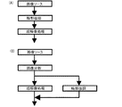
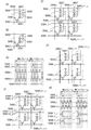
輪郭強調などの画像処理を行った後、超解像処理技術を用いて、低解像度の画像を高解像度の画像に変換する。なお、その後、バックライトを用いた局所輝度制御(ローカル・ディミング:LOCAL DIMMING)のためのデータ処理、及び/又は、オーバードライブ駆動のためのデータ処理などを行うことが可能である。 After performing image processing such as edge enhancement, a low resolution image is converted into a high resolution image using a super-resolution processing technique. After that, it is possible to perform data processing for local luminance control (local dimming) using a backlight and / or data processing for overdrive driving.
または、輪郭強調などの画像処理、および、フレーム周波数を高くして表示するためのフレームデータの補間処理を行った後、超解像処理技術を用いて、低解像度の画像を高解像度の画像に変換する。なお、その後、バックライトを用いた局所輝度制御(ローカル・ディミング:LOCAL DIMMING)のためのデータ処理、及び/又は、オーバードライブ駆動のためのデータ処理などを行うことが可能である。 Or, after performing image processing such as edge enhancement and interpolation of frame data for display at a higher frame frequency, a low-resolution image is converted to a high-resolution image using super-resolution processing technology. Convert. After that, it is possible to perform data processing for local luminance control (local dimming) using a backlight and / or data processing for overdrive driving.
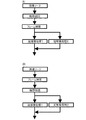
または、輪郭強調などの画像処理と、超解像処理(低解像度の画像を高解像度の画像に変換)とを同時に行う。なお、その後、バックライトを用いた局所輝度制御(ローカル・ディミング:LOCAL DIMMING)のためのデータ処理、及び/又は、オーバードライブ駆動のためのデータ処理などを行うことが可能である。 Alternatively, image processing such as edge enhancement and super-resolution processing (converting a low-resolution image into a high-resolution image) are performed simultaneously. After that, it is possible to perform data processing for local luminance control (local dimming) using a backlight and / or data processing for overdrive driving.
従って、輪郭強調処理を行う第1のステップと、超解像処理を行う第2のステップとを有し、前記第1のステップの後で、前記第2のステップが行われることを特徴とする液晶表示装置の駆動方法が提供される。 Therefore, the method has a first step of performing edge enhancement processing and a second step of performing super-resolution processing, and the second step is performed after the first step. A method for driving a liquid crystal display device is provided.
または、画像を分析する第1のステップと輪郭強調処理を行う第2のステップと、超解像処理を行う第3のステップとを有し、前記第1のステップの後で、前記第2のステップまたは前記第3のステップが行われ、前記第2のステップと、前記第3のステップとが、同時に行われる期間を有することを特徴とする液晶表示装置の駆動方法が提供される。 Alternatively, the method includes a first step of analyzing an image, a second step of performing an edge enhancement process, and a third step of performing a super-resolution process, and the second step after the first step. There is provided a method for driving a liquid crystal display device, characterized in that the step or the third step is performed, and the second step and the third step have a period in which they are performed simultaneously.
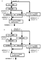
または、輪郭強調処理を行う第1のステップと、フレーム補間処理を行う第2のステップと、第1の超解像処理を行う第3のステップと、第2の超解像処理を行う第4のステップとを有し、前記第1のステップ、または、前記第2のステップの後で、前記第3のステップ、または、前期第4のステップが行われることを特徴とする液晶表示装置の駆動方法が提供される。 Alternatively, a first step for performing contour enhancement processing, a second step for performing frame interpolation processing, a third step for performing first super-resolution processing, and a fourth step for performing second super-resolution processing. And driving the liquid crystal display device, wherein the third step or the fourth step is performed after the first step or the second step. A method is provided.
または、輪郭強調処理を行う第1のステップと、フレーム補間処理を行う第2のステップと、超解像処理を行う第3のステップと、ローカルディミング処理を行う第4のステップとを有し、前記第1のステップ、または、前記第2のステップの後で、前記第3のステップが行われ、前記第3のステップの後で、前記第4のステップが行われることを特徴とする液晶表示装置の駆動方法が提供される。 Alternatively, the method includes a first step for performing contour enhancement processing, a second step for performing frame interpolation processing, a third step for performing super-resolution processing, and a fourth step for performing local dimming processing. The liquid crystal display, wherein the third step is performed after the first step or the second step, and the fourth step is performed after the third step. A method of driving the apparatus is provided.
または、輪郭強調処理を行う第1のステップと、フレーム補間処理を行う第2のステップと、超解像処理を行う第3のステップと、オーバードライブ処理を行う第4のステップとを有し、前記第1のステップ、または、前記第2のステップの後で、前記第3のステップが行われ、前記第3のステップの後で、前記第4のステップが行われることを特徴とする液晶表示装置の駆動方法が提供される。 Alternatively, the method includes a first step for performing contour enhancement processing, a second step for performing frame interpolation processing, a third step for performing super-resolution processing, and a fourth step for performing overdrive processing, The liquid crystal display, wherein the third step is performed after the first step or the second step, and the fourth step is performed after the third step. A method of driving the apparatus is provided.
または、輪郭強調処理を行う第1のステップと、フレーム補間処理を行う第2のステップと、超解像処理を行う第3のステップと、ローカルディミング処理を行う第4のステップとを有し、オーバードライブ処理を行う第5のステップとを有し、前記第1のステップ、または、前記第2のステップの後で、前記第3のステップが行われ、前記第3のステップの後で、前記第4のステップが行われ、前記第4のステップの後で、前記第5のステップが行われることを特徴とする液晶表示装置の駆動方法が提供される。 Alternatively, the method includes a first step for performing contour enhancement processing, a second step for performing frame interpolation processing, a third step for performing super-resolution processing, and a fourth step for performing local dimming processing. A fifth step of performing an overdrive process, the third step is performed after the first step or the second step, and the third step is performed after the third step. A method for driving a liquid crystal display device is provided, wherein a fourth step is performed, and the fifth step is performed after the fourth step.
なお、スイッチとしては、様々な形態のものを用いることができる。スイッチの一例としては、電気的スイッチ又は機械的なスイッチなどを用いることができる。つまり、スイッチは、電流を制御できるものであればよく、特定のものに限定されない。スイッチの一例としては、トランジスタ(例えば、バイポーラトランジスタ、MOSトランジスタなど)、ダイオード(例えば、PNダイオード、PINダイオード、ショットキーダイオード、MIM(Metal Insulator Metal)ダイオード、MIS(Metal Insulator Semiconductor)ダイオード、ダイオード接続のトランジスタなど)、又はこれらを組み合わせた論理回路などがある。機械的なスイッチの一例としては、デジタルマイクロミラーデバイス(DMD)のように、MEMS(マイクロ・エレクトロ・メカニカル・システム)技術を用いたスイッチがある。そのスイッチは、機械的に動かすことが可能な電極を有し、その電極が動くことによって、導通と非導通とを制御して動作する。 Note that various types of switches can be used as the switch. As an example of the switch, an electrical switch or a mechanical switch can be used. That is, the switch is not limited to a specific one as long as it can control the current. Examples of switches include transistors (eg, bipolar transistors, MOS transistors, etc.), diodes (eg, PN diodes, PIN diodes, Schottky diodes, MIM (Metal Insulator Metal) diodes, MIS (Metal Insulator Semiconductor) diodes, and diode connections. Or a logic circuit combining these transistors. An example of a mechanical switch is a switch using MEMS (micro electro mechanical system) technology, such as a digital micromirror device (DMD). The switch has an electrode that can be moved mechanically, and operates by controlling conduction and non-conduction by moving the electrode.
なお、スイッチとしてトランジスタを用いる場合、そのトランジスタは単なるスイッチとして動作するため、トランジスタの極性(導電型)は特に限定されない。ただし、オフ電流を抑えたい場合、オフ電流が少ない方の極性のトランジスタを用いることが望ましい。オフ電流が少ないトランジスタの一例としては、LDD領域を有するトランジスタ、又はマルチゲート構造を有するトランジスタなどがある。 Note that in the case where a transistor is used as a switch, the transistor operates as a mere switch, and thus the polarity (conductivity type) of the transistor is not particularly limited. However, when it is desired to suppress off-state current, it is desirable to use a transistor having a polarity with smaller off-state current. As an example of a transistor with low off-state current, a transistor having an LDD region, a transistor having a multi-gate structure, or the like can be given.
なお、スイッチとしてトランジスタを用いる場合、スイッチとして動作させるトランジスタのソースの電位が、低電位側電源(Vss、GND、0Vなど)の電位に近い値で動作する場合は、スイッチとしてNチャネル型トランジスタを用いることが望ましい。反対に、ソースの電位が、高電位側電源(Vddなど)の電位に近い値で動作する場合は、スイッチとしてPチャネル型トランジスタを用いることが望ましい。なぜなら、Nチャネル型トランジスタではソースが低電位側電源の電位に近い値で動作するとき、Pチャネル型トランジスタではソースが高電位側電源の電位に近い値で動作するとき、ゲートとソースとの間の電圧の絶対値を大きくできるからである。そのため、スイッチとして、より正確な動作を行うことができるからである。または、トランジスタがソースフォロワ動作をしてしまうことが少ないため、出力電圧の大きさが小さくなってしまうことが少ないからである。 Note that in the case where a transistor is used as a switch, an N-channel transistor is used as a switch when the potential of the source of the transistor that operates as a switch operates at a value close to the potential of the low-potential power supply (Vss, GND, 0 V, or the like). It is desirable to use it. On the other hand, in the case where the source potential operates at a value close to the potential of the high potential side power supply (Vdd or the like), it is desirable to use a P-channel transistor as a switch. This is because when an N-channel transistor operates at a value close to the potential of the low-potential side power supply, and a P-channel transistor operates at a value close to the potential of the high-potential side power supply, This is because the absolute value of the voltage can be increased. Therefore, a more accurate operation can be performed as a switch. Alternatively, since the transistor rarely performs a source follower operation, the output voltage is rarely reduced.
なお、スイッチとして、Nチャネル型トランジスタとPチャネル型トランジスタとの両方を用いて、CMOS型のスイッチを用いてもよい。CMOS型のスイッチにすると、Pチャネル型トランジスタとNチャネル型トランジスタとのどちらか一方が導通すれば、電流が流れるため、スイッチとして機能しやすくなる。よって、スイッチへの入力信号の電圧が高い場合でも、低い場合でも、適切に電圧を出力させることができる。または、スイッチをオン又はオフさせるための信号の電圧振幅値を小さくすることが出来るので、消費電力を小さくすることができる。 Note that a CMOS switch may be used as the switch by using both an N-channel transistor and a P-channel transistor. When a CMOS switch is used, if either the P-channel transistor or the N-channel transistor is turned on, current flows, so that the switch can easily function as a switch. Therefore, even when the voltage of the input signal to the switch is high or low, the voltage can be appropriately output. Alternatively, since the voltage amplitude value of a signal for turning on or off the switch can be reduced, power consumption can be reduced.
なお、スイッチとしてトランジスタを用いる場合、スイッチは、入力端子(ソースまたはドレインの一方)と、出力端子(ソースまたはドレインの他方)と、導通を制御する端子(ゲート)とを有している場合がある。一方、スイッチとしてダイオードを用いる場合、スイッチは、導通を制御する端子を有していない場合がある。したがって、トランジスタよりもダイオードをスイッチとして用いた方が、端子を制御するための配線を少なくすることが出来る。 Note that in the case where a transistor is used as the switch, the switch may include an input terminal (one of the source and the drain), an output terminal (the other of the source and the drain), and a terminal (gate) that controls conduction. is there. On the other hand, when a diode is used as the switch, the switch may not have a terminal for controlling conduction. Therefore, the use of a diode as a switch rather than a transistor can reduce wiring for controlling the terminal.
なお、表示素子、表示素子を有する装置である表示装置、発光素子、及び発光素子を有する装置である発光装置は、様々な形態を用いること、又は様々な素子を有することが出来る。表示素子、表示装置、発光素子又は発光装置の一例としては、EL(エレクトロルミネッセンス)素子(有機物及び無機物を含むEL素子、有機EL素子、無機EL素子)、LED(白色LED、赤色LED、緑色LED、青色LEDなど)、トランジスタ(電流に応じて発光するトランジスタ)、電子放出素子、液晶素子、電子インク、電気泳動素子、グレーティングライトバルブ(GLV)、プラズマディスプレイパネル(PDP)、デジタルマイクロミラーデバイス(DMD)、圧電セラミックディスプレイ、カーボンナノチューブ、など、電気磁気的作用により、コントラスト、輝度、反射率、透過率などが変化する表示媒体を有するものがある。EL素子を用いた表示装置の一例としては、ELディスプレイなどがある。電子放出素子を用いた表示装置の一例としては、フィールドエミッションディスプレイ(FED)又はSED方式平面型ディスプレイ(SED:Surface−conduction Electron−emitter Disply)などがある。液晶素子を用いた表示装置の一例としては、液晶ディスプレイ(透過型液晶ディスプレイ、半透過型液晶ディスプレイ、反射型液晶ディスプレイ、直視型液晶ディスプレイ、投射型液晶ディスプレイ)などがある。電子インク又は電気泳動素子を用いた表示装置の一例としては、電子ペーパーなどがある。 Note that a display element, a display device that is a device including a display element, a light-emitting element, and a light-emitting device that is a device including a light-emitting element can have various modes or have various elements. As an example of a display element, a display device, a light emitting element, or a light emitting device, an EL (electroluminescence) element (an EL element including an organic substance and an inorganic substance, an organic EL element, an inorganic EL element), an LED (white LED, red LED, green LED) , Blue LEDs, etc.), transistors (transistors that emit light in response to current), electron-emitting devices, liquid crystal devices, electronic ink, electrophoretic devices, grating light valves (GLV), plasma display panels (PDP), digital micromirror devices ( Some of them have display media whose contrast, brightness, reflectance, transmittance, and the like change due to an electromagnetic action, such as DMD), piezoelectric ceramic displays, and carbon nanotubes. An example of a display device using an EL element is an EL display. As an example of a display device using an electron-emitting device, there is a field emission display (FED), a SED type flat display (SED: Surface-conduction Electron-emitter Display), or the like. As an example of a display device using a liquid crystal element, there is a liquid crystal display (a transmissive liquid crystal display, a transflective liquid crystal display, a reflective liquid crystal display, a direct view liquid crystal display, a projection liquid crystal display) and the like. An example of a display device using electronic ink or an electrophoretic element is electronic paper.
EL素子の一例としては、陽極と、陰極と、陽極と陰極との間に挟まれたEL層と、を有する素子などがある。EL層の一例としては、1重項励起子からの発光(蛍光)を利用するもの、3重項励起子からの発光(燐光)を利用するもの、1重項励起子からの発光(蛍光)を利用するものと3重項励起子からの発光(燐光)を利用するものとを含むもの、有機物によって形成されたもの、無機物によって形成されたもの、有機物によって形成されたものと無機物によって形成されたものとを含むもの、高分子の材料を含むもの、低分子の材料を含むもの、又は高分子の材料と低分子の材料とを含むもの、などがある。ただし、これに限定されず、EL素子として様々なものを用いることができる。 As an example of an EL element, there is an element having an anode, a cathode, and an EL layer sandwiched between the anode and the cathode. Examples of the EL layer include those that use light emission (fluorescence) from singlet excitons, those that use light emission (phosphorescence) from triplet excitons, and light emission (fluorescence) from singlet excitons. And those using triplet excitons (phosphorescence), those made of organic matter, those made of inorganic matter, those made of organic matter and those made of inorganic matter And the like, those containing a high molecular material, those containing a low molecular material, and those containing a high molecular material and a low molecular material. However, the present invention is not limited to this, and various EL elements can be used.
電子放出素子の一例としては、陰極に高電界を集中して電子を引き出す素子などがある。具体的には、電子放出素子の一例としては、スピント型、カーボンナノチューブ(CNT)型、金属―絶縁体―金属を積層したMIM(Metal−Insulator−Metal)型、金属―絶縁体―半導体を積層したMIS(Metal−Insulator−Semiconductor)型、MOS型、シリコン型、薄膜ダイオード型、ダイヤモンド型、金属―絶縁体―半導体−金属型等の薄膜型、HEED型、EL型、ポーラスシリコン型、又は表面伝導(SCE)型などがある。ただし、これに限定されず、電子放出素子として様々なものを用いることができる。 As an example of the electron-emitting device, there is a device that draws electrons by concentrating a high electric field on the cathode. Specifically, as an example of an electron emitting device, a Spindt type, a carbon nanotube (CNT) type, a metal-insulator-metal (MIM) type in which metal-insulator-metal is laminated, and a metal-insulator-semiconductor are laminated. MIS (Metal-Insulator-Semiconductor) type, MOS type, silicon type, thin film diode type, diamond type, metal-insulator-semiconductor-metal type thin film type, HEED type, EL type, porous silicon type, or surface There is a conduction (SCE) type. However, the present invention is not limited to this, and various types of electron-emitting devices can be used.
液晶素子の一例としては、液晶の光学的変調作用によって光の透過又は非透過を制御する素子がある。その素子は一対の電極と液晶層により構造されることが可能である。なお、液晶の光学的変調作用は、液晶にかかる電界(横方向の電界、縦方向の電界又は斜め方向の電界を含む)によって制御される。なお、具体的には、液晶素子の一例としては、ネマチック液晶、コレステリック液晶、スメクチック液晶、ディスコチック液晶、サーモトロピック液晶、リオトロピック液晶、低分子液晶、高分子液晶、高分子分散型液晶(PDLC)、強誘電液晶、反強誘電液晶、主鎖型液晶、側鎖型高分子液晶、プラズマアドレス液晶(PALC)、バナナ型液晶などを挙げることができる。また、液晶の駆動方式としては、TN(Twisted Nematic)モード、STN(Super Twisted Nematic)モード、IPS(In−Plane−Switching)モード、FFS(Fringe Field Switching)モード、MVA(Multi−domain Vertical Alignment)モード、PVA(Patterned Vertical Alignment)モード、ASV(Advanced Super View)モード、ASM(Axially Symmetric aligned Micro−cell)モード、OCB(Optically Compensated Birefringence)モード、ECB(Electrically Controlled Birefringence)モード、FLC(Ferroelectric Liquid Crystal)モード、AFLC(AntiFerroelectric Liquid Crystal)モード、PDLC(Polymer Dispersed Liquid Crystal)モード、ゲストホストモード、ブルー相(Blue Phase)モードなどがある。ただし、これに限定されず、液晶素子及びその駆動方法として様々なものを用いることができる。 As an example of a liquid crystal element, there is an element that controls transmission or non-transmission of light by an optical modulation action of liquid crystal. The element can be structured by a pair of electrodes and a liquid crystal layer. Note that the optical modulation action of the liquid crystal is controlled by an electric field applied to the liquid crystal (including a horizontal electric field, a vertical electric field, or an oblique electric field). Specifically, examples of liquid crystal elements include nematic liquid crystals, cholesteric liquid crystals, smectic liquid crystals, discotic liquid crystals, thermotropic liquid crystals, lyotropic liquid crystals, low molecular liquid crystals, polymer liquid crystals, and polymer dispersed liquid crystals (PDLC). And ferroelectric liquid crystal, antiferroelectric liquid crystal, main chain liquid crystal, side chain polymer liquid crystal, plasma addressed liquid crystal (PALC), and banana liquid crystal. In addition, as a liquid crystal driving method, a TN (Twisted Nematic) mode, an STN (Super Twisted Nematic) mode, an IPS (In-Plane-Switching) mode, an FFS (Fringe Field Switching) mode, and an MVA (Multi-Antificent Magnetic Alignment) Mode, PVA (Patterned Vertical Alignment) mode, ASV (Advanced Super View) mode, ASM (Axial Symmetrically Coated MicroBell) mode, OCB (Optically Compensated BEC) mode Included birefringence mode, FLC (Ferroelectric Liquid Crystal) mode, AFLC (Antiferroelectric Liquid Crystal) mode, PDLC (Polymer Dispersed Liquid Crystal) mode, guest mode, B guest mode, guest mode. However, the present invention is not limited to this, and various liquid crystal elements and driving methods thereof can be used.
電子ペーパーの一例としては、分子により表示されるもの(光学異方性、染料分子配向など)、粒子により表示されるもの(電気泳動、粒子移動、粒子回転、相変化など)、フィルムの一端が移動することにより表示されるもの、分子の発色/相変化により表示されるもの、分子の光吸収により表示されるもの、又は電子とホールが結合して自発光により表示されるものなどを用いることができる。具体的には、電子ペーパーの表示方法の一例としては、マイクロカプセル型電気泳動、水平移動型電気泳動、垂直移動型電気泳動、球状ツイストボール、磁気ツイストボール、円柱ツイストボール方式、帯電トナー、電子粉流体、磁気泳動型、磁気感熱式、エレクトロウェッテイング、光散乱(透明/白濁変化)、コレステリック液晶/光導電層、コレステリック液晶、双安定性ネマチック液晶、強誘電性液晶、2色性色素・液晶分散型、可動フィルム、ロイコ染料による発消色、フォトクロミック、エレクトロクロミック、エレクトロデポジション、フレキシブル有機ELなどがある。ただし、これに限定されず、電子ペーパー及びその表示方式として様々なものを用いることができる。ここで、マイクロカプセル型電気泳動を用いることによって、電気泳動方式の欠点である泳動粒子の凝集、沈殿を解決することができる。電子粉流体は、高速応答性、高反射率、広視野角、低消費電力、メモリ性などのメリットを有する。 Examples of electronic paper include those displayed by molecules (optical anisotropy, dye molecule orientation, etc.), those displayed by particles (electrophoresis, particle movement, particle rotation, phase change, etc.), and one end of the film Use those that are displayed by moving, those that are displayed by color development / phase change of molecules, those that are displayed by light absorption of molecules, or those that are displayed by self-luminescence by combining electrons and holes. Can do. Specifically, examples of electronic paper display methods include microcapsule electrophoresis, horizontal movement electrophoresis, vertical movement electrophoresis, spherical twist ball, magnetic twist ball, cylindrical twist ball system, charged toner, electronic Powdered fluid, magnetophoretic, magnetic thermosensitive, electrowetting, light scattering (transparency / white turbidity change), cholesteric liquid crystal / photoconductive layer, cholesteric liquid crystal, bistable nematic liquid crystal, ferroelectric liquid crystal, dichroic dye There are liquid crystal dispersion type, movable film, color erasing / erasing with leuco dye, photochromic, electrochromic, electrodeposition, flexible organic EL, etc. However, the present invention is not limited to this, and various types of electronic paper and its display method can be used. Here, by using microcapsule electrophoresis, aggregation and precipitation of electrophoretic particles, which is a drawback of the electrophoresis system, can be solved. The electronic powder fluid has advantages such as high-speed response, high reflectivity, wide viewing angle, low power consumption, and memory properties.
プラズマディスプレイパネルの一例としては、電極を表面に形成した基板と、電極及び微小な溝を表面に形成し且つ溝内に蛍光体層を形成した基板と、を狭い間隔で対向させて、希ガスを封入した構造を有するものなどがある。他にも、プラズマディスプレイパネルの一例としては、プラズマチューブを上下からフィルム状の電極で挟み込んだ構造を有するものなどがある。プラズマチューブとは、ガラスチューブ内に、放電ガス、RGBそれぞれの蛍光体などを封止したものである。電極間に電圧をかけることによって紫外線を発生させ、蛍光体を光らせることで、表示を行うことができる。なお、プラズマディスプレイパネルの一例としては、DC型PDP、又はAC型PDPなどがある。ここで、プラズマディスプレイパネルの駆動方式としては、AWS(Address While Sustain)駆動、サブフレームをリセット期間、アドレス期間、維持期間に分割するADS(Address Display Separated)駆動、CLEAR(HI‐CONTRAST&LOW ENERGY ADDRESS&REDUCTION OF FALSE CONTOUR SEQUENCE)駆動、ALIS(Alternate Lighting of Surfaces)方式、TERES(Technology of Reciprocal Sustainer)駆動などを用いることができる。ただし、これに限定されず、プラズマディスプレイパネルとして様々なものを用いることができる。 As an example of a plasma display panel, a substrate having electrodes formed on the surface thereof and a substrate having electrodes and minute grooves formed on the surface and having a phosphor layer formed in the grooves are opposed to each other at a narrow interval, so that a rare gas is provided. Some have a structure in which is enclosed. In addition, as an example of the plasma display panel, there is one having a structure in which a plasma tube is sandwiched from above and below by film-like electrodes. The plasma tube is formed by sealing a discharge gas, RGB phosphors, and the like in a glass tube. By applying a voltage between the electrodes, ultraviolet rays are generated, and the phosphor is lit, so that display can be performed. An example of the plasma display panel is a DC type PDP or an AC type PDP. Here, as a driving method of the plasma display panel, AWS (Address Wide Sustain) driving, ADS (Address Display Separated) driving in which a subframe is divided into a reset period, an address period, and a sustaining period, CLEAR (HI-CONTRAST & LOW ENDERGRED ADDRESD ADDRESD ADDRESD ADDRESD ADDLESD FALSE CONTROL SEQUENCE, ALIS (Alternate Lighting of Surfaces) system, TERES (Technology of Reciprocal Sustainer) drive, etc. can be used. However, the present invention is not limited to this, and various types of plasma display panels can be used.
なお、光源を必要とする表示装置、例えば、液晶ディスプレイ(透過型液晶ディスプレイ、半透過型液晶ディスプレイ、反射型液晶ディスプレイ、直視型液晶ディスプレイ、投射型液晶ディスプレイ)、グレーティングライトバルブ(GLV)を用いた表示装置、デジタルマイクロミラーデバイス(DMD)を用いた表示装置などの光源の一例としては、エレクトロルミネッセンス、冷陰極管、熱陰極管、LED、レーザー光源、水銀ランプなどを用いることができる。ただし、これに限定されず、光源として様々なものを用いることができる。 Note that a display device that requires a light source, such as a liquid crystal display (transmission type liquid crystal display, transflective type liquid crystal display, reflection type liquid crystal display, direct view type liquid crystal display, projection type liquid crystal display), or a grating light valve (GLV) is used. As an example of a light source such as a display device using a conventional display device or a display device using a digital micromirror device (DMD), electroluminescence, a cold cathode tube, a hot cathode tube, an LED, a laser light source, a mercury lamp, or the like can be used. However, the present invention is not limited to this, and various light sources can be used.
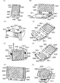
なお、トランジスタとして、様々な構造のトランジスタを用いることが出来る。よって、用いるトランジスタの種類に限定はない。トランジスタの一例としては、非晶質シリコン、多結晶シリコン、微結晶(マイクロクリスタル、ナノクリスタル、セミアモルファスとも言う)シリコンなどに代表される非単結晶半導体膜を有する薄膜トランジスタ(TFT)などを用いることが出来る。TFTを用いる場合、様々なメリットがある。例えば、単結晶シリコンの場合よりも低い温度で製造できるため、製造コストの削減、又は製造装置の大型化を図ることができる。製造装置を大きくできるため、大型基板上に製造できる。そのため、同時に多くの個数の表示装置を製造できるため、低コストで製造できる。または、製造温度が低いため、耐熱性の低い基板を用いることができる。そのため、透光性を有する基板上にトランジスタを製造できる。または、透光性を有する基板上のトランジスタを用いて表示素子での光の透過を制御することが出来る。または、トランジスタの膜厚が薄いため、トランジスタを形成する膜の一部は、光を透過させることが出来る。そのため、開口率を向上させることができる。 Note that transistors with various structures can be used as the transistor. Thus, there is no limitation on the type of transistor used. As an example of a transistor, a thin film transistor (TFT) including a non-single-crystal semiconductor film typified by amorphous silicon, polycrystalline silicon, microcrystalline (also referred to as microcrystal, nanocrystal, or semi-amorphous) silicon is used. I can do it. When using TFT, there are various advantages. For example, since manufacturing can be performed at a lower temperature than that of single crystal silicon, manufacturing cost can be reduced or a manufacturing apparatus can be increased in size. Since the manufacturing apparatus can be enlarged, it can be manufactured on a large substrate. Therefore, since a large number of display devices can be manufactured at the same time, it can be manufactured at low cost. Alternatively, since the manufacturing temperature is low, a substrate with low heat resistance can be used. Therefore, a transistor can be manufactured over a light-transmitting substrate. Alternatively, light transmission through the display element can be controlled using a transistor over a light-transmitting substrate. Alternatively, since the thickness of the transistor is small, part of the film forming the transistor can transmit light. Therefore, the aperture ratio can be improved.
なお、多結晶シリコンを製造するときに、触媒(ニッケルなど)を用いることにより、結晶性をさらに向上させ、電気特性のよいトランジスタを製造することが可能となる。その結果、ゲートドライバ回路(走査線駆動回路)、ソースドライバ回路(信号線駆動回路)、及び信号処理回路(信号生成回路、ガンマ補正回路、DA変換回路など)を基板上に一体形成することが出来る。 Note that by using a catalyst (such as nickel) when manufacturing polycrystalline silicon, it is possible to further improve crystallinity and to manufacture a transistor with favorable electrical characteristics. As a result, a gate driver circuit (scanning line driving circuit), a source driver circuit (signal line driving circuit), and a signal processing circuit (signal generation circuit, gamma correction circuit, DA conversion circuit, etc.) can be integrally formed on the substrate. I can do it.
なお、微結晶シリコンを製造するときに、触媒(ニッケルなど)を用いることにより、結晶性をさらに向上させ、電気特性のよいトランジスタを製造することが可能となる。このとき、レーザー照射を行うことなく、熱処理を加えるだけで、結晶性を向上させることも可能である。その結果、ソースドライバ回路の一部(アナログスイッチなど)及びゲートドライバ回路(走査線駆動回路)を基板上に一体形成することが出来る。なお、結晶化のためにレーザー照射を行わない場合は、シリコンの結晶性のムラを抑えることができる。そのため、画質の向上した画像を表示することが出来る。ただし、触媒(ニッケルなど)を用いずに、多結晶シリコン又は微結晶シリコンを製造することは可能である。 Note that when a microcrystalline silicon is manufactured, by using a catalyst (such as nickel), crystallinity can be further improved and a transistor with favorable electrical characteristics can be manufactured. At this time, it is also possible to improve crystallinity only by performing heat treatment without performing laser irradiation. As a result, part of the source driver circuit (such as an analog switch) and a gate driver circuit (scanning line driver circuit) can be formed over the substrate. Note that in the case where laser irradiation is not performed for crystallization, unevenness in crystallinity of silicon can be suppressed. Therefore, an image with improved image quality can be displayed. However, it is possible to produce polycrystalline silicon or microcrystalline silicon without using a catalyst (such as nickel).
なお、シリコンの結晶性を、多結晶又は微結晶などへと向上させることは、パネル全体で行うことが望ましいが、それに限定されない。パネルの一部の領域のみにおいて、シリコンの結晶性を向上させてもよい。選択的に結晶性を向上させることは、レーザー光を選択的に照射することなどにより可能である。例えば、画素以外の領域である周辺回路領域にのみ、ゲートドライバ回路及びソースドライバ回路などの領域にのみ、又はソースドライバ回路の一部(例えば、アナログスイッチ)の領域にのみ、にレーザー光を照射してもよい。その結果、回路を高速に動作させる必要がある領域にのみ、シリコンの結晶性を向上させることができる。画素領域は、高速に動作させる必要性が低いため、結晶性が向上されなくても、問題なく画素回路を動作させることが出来る。こうすることによって、結晶性を向上させる領域が少なくて済むため、製造工程も短くすることが出来る。そのため、スループットが向上し、製造コストを低減させることが出来る。または、必要とされる製造装置の数も少ない数で製造できるため、製造コストを低減させることが出来る。 Note that it is preferable to improve the crystallinity of silicon to be polycrystalline or microcrystalline, but the present invention is not limited to this. The crystallinity of silicon may be improved only in a partial region of the panel. The crystallinity can be selectively improved by selectively irradiating laser light. For example, laser light is irradiated only to a peripheral circuit region other than a pixel, only to a region such as a gate driver circuit and a source driver circuit, or only a part of a source driver circuit (for example, an analog switch). May be. As a result, the crystallinity of silicon can be improved only in a region where the circuit needs to operate at high speed. Since it is not necessary to operate the pixel region at high speed, the pixel circuit can be operated without any problem even if the crystallinity is not improved. By doing so, the region for improving crystallinity can be reduced, and the manufacturing process can be shortened. Therefore, throughput can be improved and manufacturing cost can be reduced. Alternatively, the manufacturing cost can be reduced because the manufacturing apparatus can be manufactured with a small number of manufacturing apparatuses.
なお、トランジスタの一例としては、ZnO、a−InGaZnO、SiGe、GaAs、IZO、ITO、SnO、TiO、AlZnSnO(AZTO)などの化合物半導体又は酸化物半導体を有するトランジスタ又は、これらの化合物半導体又は酸化物半導体を薄膜化した薄膜トランジスタなどを用いることが出来る。これらにより、製造温度を低くできるので、例えば、室温でトランジスタを製造することが可能となる。その結果、耐熱性の低い基板、例えばプラスチック基板又はフィルム基板などに直接トランジスタを形成することが出来る。なお、これらの化合物半導体又は酸化物半導体を、トランジスタのチャネル部分に用いるだけでなく、それ以外の用途で用いることも出来る。例えば、これらの化合物半導体又は酸化物半導体を配線、抵抗素子、画素電極、又は透光性を有する電極などとして用いることができる。それらをトランジスタと同時に成膜又は形成することが可能なため、コストを低減できる。 Note that as an example of a transistor, a transistor having a compound semiconductor or an oxide semiconductor such as ZnO, a-InGaZnO, SiGe, GaAs, IZO, ITO, SnO, TiO, and AlZnSnO (AZTO), or a compound semiconductor or oxide thereof. A thin film transistor obtained by thinning a semiconductor can be used. As a result, the manufacturing temperature can be lowered, so that the transistor can be manufactured at room temperature, for example. As a result, the transistor can be formed directly on a substrate having low heat resistance, such as a plastic substrate or a film substrate. Note that these compound semiconductors or oxide semiconductors can be used not only for a channel portion of a transistor but also for other purposes. For example, these compound semiconductors or oxide semiconductors can be used as a wiring, a resistance element, a pixel electrode, a light-transmitting electrode, or the like. Since these can be formed or formed simultaneously with the transistor, cost can be reduced.
なお、トランジスタの一例としては、インクジェット法又は印刷法を用いて形成したトランジスタなどを用いることが出来る。これらにより、室温で製造、低真空度で製造、又は大型基板上に製造することができる。よって、マスク(レチクル)を用いなくても製造することが可能となるため、トランジスタのレイアウトを容易に変更することが出来る。または、レジストを用いらずに製造することが可能なので、材料費が安くなり、工程数を削減できる。または、必要な部分にのみ膜を付けることが可能なので、全面に成膜した後でエッチングする、という製法よりも、材料が無駄にならず、低コストにできる。 Note that as an example of a transistor, a transistor formed using an inkjet method or a printing method can be used. By these, it can manufacture at room temperature, manufacture at a low vacuum degree, or can manufacture on a large sized board | substrate. Therefore, since the transistor can be manufactured without using a mask (reticle), the layout of the transistor can be easily changed. Alternatively, since it can be manufactured without using a resist, the material cost is reduced and the number of processes can be reduced. Alternatively, since a film can be formed only on a necessary portion, the material is not wasted and the cost can be reduced as compared with a manufacturing method in which etching is performed after film formation on the entire surface.
なお、トランジスタの一例としては、有機半導体やカーボンナノチューブを有するトランジスタ等を用いることができる。これらにより、曲げることが可能な基板上にトランジスタを形成することが出来る。このような基板を用いた半導体装置は、衝撃に強くすることができる。 Note that as an example of a transistor, a transistor including an organic semiconductor or a carbon nanotube can be used. Thus, a transistor can be formed over a substrate that can be bent. A semiconductor device using such a substrate can be resistant to impact.
なお、トランジスタとしては、他にも様々な構造のトランジスタを用いることができる。例えば、トランジスタとして、MOS型トランジスタ、接合型トランジスタ、バイポーラトランジスタなどを用いることが出来る。トランジスタとしてMOS型トランジスタを用いることにより、トランジスタのサイズを小さくすることが出来る。よって、多数のトランジスタを搭載することができる。トランジスタとしてバイポーラトランジスタを用いることにより、大きな電流を流すことが出来る。よって、高速に回路を動作させることができる。なお、MOS型トランジスタとバイポーラトランジスタとを1つの基板に混在させて形成してもよい。これにより、低消費電力、小型化、高速動作などを実現することが出来る。 Note that transistors having various structures can be used as the transistor. For example, a MOS transistor, a junction transistor, a bipolar transistor, or the like can be used as the transistor. By using a MOS transistor as the transistor, the size of the transistor can be reduced. Therefore, a large number of transistors can be mounted. By using a bipolar transistor as the transistor, a large current can flow. Therefore, the circuit can be operated at high speed. Note that a MOS transistor and a bipolar transistor may be mixed on one substrate. Thereby, low power consumption, miniaturization, high-speed operation, etc. can be realized.
なお、トランジスタの一例としては、ゲート電極が2個以上のマルチゲート構造のトランジスタを用いることができる。マルチゲート構造にすると、チャネル領域が直列に接続されるため、複数のトランジスタが直列に接続された構造となる。よって、マルチゲート構造により、オフ電流の低減、トランジスタの耐圧向上(信頼性の向上)を図ることができる。または、マルチゲート構造により、飽和領域で動作する時に、ドレインとソースとの間の電圧が変化しても、ドレインとソースとの間の電流があまり変化せず、電圧・電流特性の傾きをフラットにすることができる。電圧・電流特性の傾きがフラットである特性を利用すると、理想的な電流源回路、又は非常に高い抵抗値をもつ能動負荷を実現することが出来る。その結果、特性のよい差動回路又はカレントミラー回路などを実現することが出来る。 Note that as an example of a transistor, a multi-gate transistor having two or more gate electrodes can be used. When the multi-gate structure is used, the channel regions are connected in series, so that a plurality of transistors are connected in series. Therefore, the off-state current can be reduced and the withstand voltage of the transistor can be improved (reliability can be improved) by the multi-gate structure. Or, due to the multi-gate structure, even when the voltage between the drain and source changes when operating in the saturation region, the current between the drain and source does not change much, and the slope of the voltage / current characteristics is flat. Can be. By using the characteristic that the slope of the voltage / current characteristic is flat, an ideal current source circuit or an active load having a very high resistance value can be realized. As a result, a differential circuit or a current mirror circuit with good characteristics can be realized.
なお、トランジスタの一例としては、チャネルの上下にゲート電極が配置されている構造のトランジスタを適用することができる。チャネルの上下にゲート電極が配置される構造にすることにより、複数のトランジスタが並列に接続されたような回路構成となる。よって、チャネル領域が増えるため、電流値の増加を図ることができる。または、チャネルの上下にゲート電極が配置されている構造にすることにより、空乏層ができやすくなるため、S値の改善を図ることができる。 Note that as an example of a transistor, a transistor with a structure where gate electrodes are formed above and below a channel can be used. With a structure in which gate electrodes are arranged above and below a channel, a circuit configuration in which a plurality of transistors are connected in parallel is obtained. Therefore, since the channel region increases, the current value can be increased. Alternatively, a structure in which gate electrodes are provided above and below a channel facilitates the formation of a depletion layer, so that the S value can be improved.
なお、トランジスタの一例としては、チャネル領域の上にゲート電極が配置されている構造、チャネル領域の下にゲート電極が配置されている構造、正スタガ構造、逆スタガ構造、チャネル領域を複数の領域に分けた構造、チャネル領域を並列に接続した構造、又はチャネル領域が直列に接続する構造などのトランジスタを用いることができる。 Note that as an example of a transistor, a structure in which a gate electrode is disposed over a channel region, a structure in which a gate electrode is disposed under a channel region, a normal staggered structure, an inverted staggered structure, and a channel region in a plurality of regions Transistors having a structure divided into two, a structure in which channel regions are connected in parallel, or a structure in which channel regions are connected in series can be used.
なお、トランジスタの一例としては、チャネル領域(もしくはその一部)にソース電極やドレイン電極が重なっている構造のトランジスタを用いることができる。チャネル領域(もしくはその一部)にソース電極やドレイン電極が重なる構造にすることによって、チャネル領域の一部に電荷が溜まることにより動作が不安定になることを防ぐことができる。 Note that as an example of a transistor, a transistor with a structure in which a source electrode or a drain electrode overlaps with a channel region (or part thereof) can be used. With the structure where the source electrode and the drain electrode overlap with the channel region (or part thereof), unstable operation due to accumulation of electric charge in part of the channel region can be prevented.
なお、トランジスタの一例としては、LDD領域を設けた構造のトランジスタを適用できる。LDD領域を設けることにより、オフ電流の低減、又はトランジスタの耐圧向上(信頼性の向上)を図ることができる。または、LDD領域を設けることにより、飽和領域で動作する時に、ドレインとソースとの間の電圧が変化しても、ドレイン電流があまり変化せず、電圧・電流特性の傾きをフラットにすることができる。 Note that as an example of a transistor, a transistor having an LDD region can be used. By providing the LDD region, off-state current can be reduced or the breakdown voltage of the transistor can be improved (reliability improvement). Alternatively, by providing the LDD region, when operating in the saturation region, even if the voltage between the drain and the source changes, the drain current does not change much, and the slope of the voltage / current characteristics can be flattened. it can.
なお、様々な基板を用いて、トランジスタを形成することが出来る。基板の種類は、特定のものに限定されることはない。その基板の一例としては、半導体基板(例えば単結晶基板又はシリコン基板)、SOI基板、ガラス基板、石英基板、プラスチック基板、金属基板、ステンレス・スチル基板、ステンレス・スチル・ホイルを有する基板、タングステン基板、タングステン・ホイルを有する基板、可撓性基板、貼り合わせフィルム、繊維状の材料を含む紙、又は基材フィルムなどがある。ガラス基板の一例としては、バリウムホウケイ酸ガラス、アルミノホウケイ酸ガラス、又はソーダライムガラスなどがある。可撓性基板の一例としては、ポリエチレンテレフタレート(PET)、ポリエチレンナフタレート(PEN)、ポリエーテルサルフォン(PES)に代表されるプラスチック、又はアクリル等の可撓性を有する合成樹脂などがある。貼り合わせフィルムの一例としては、ポリプロピレン、ポリエステル、ビニル、ポリフッ化ビニル、又は塩化ビニルなどがある。基材フィルムの一例としては、ポリエステル、ポリアミド、ポリイミド、無機蒸着フィルム、又は紙類などがある。特に、半導体基板、単結晶基板、又はSOI基板などを用いてトランジスタを製造することによって、特性、サイズ、又は形状などのばらつきが少なく、電流能力が高く、サイズの小さいトランジスタを製造することができる。このようなトランジスタによって回路を構成すると、回路の低消費電力化、又は回路の高集積化を図ることができる。 Note that a transistor can be formed using various substrates. The kind of board | substrate is not limited to a specific thing. Examples of the substrate include a semiconductor substrate (for example, a single crystal substrate or a silicon substrate), an SOI substrate, a glass substrate, a quartz substrate, a plastic substrate, a metal substrate, a stainless steel substrate, a substrate having stainless steel foil, and a tungsten substrate. , A substrate having a tungsten foil, a flexible substrate, a laminated film, a paper containing a fibrous material, or a base film. Examples of the glass substrate include barium borosilicate glass, aluminoborosilicate glass, and soda lime glass. As an example of the flexible substrate, there are plastics typified by polyethylene terephthalate (PET), polyethylene naphthalate (PEN), and polyethersulfone (PES), or a synthetic resin having flexibility such as acrylic. Examples of the laminated film include polypropylene, polyester, vinyl, polyvinyl fluoride, or vinyl chloride. Examples of the base film include polyester, polyamide, polyimide, an inorganic vapor deposition film, and papers. In particular, by manufacturing a transistor using a semiconductor substrate, a single crystal substrate, an SOI substrate, or the like, a transistor with small variation in characteristics, size, or shape, high current capability, and small size can be manufactured. . When a circuit is formed using such transistors, the power consumption of the circuit can be reduced or the circuit can be highly integrated.
なお、ある基板を用いてトランジスタを形成し、その後、別の基板にトランジスタを転置し、別の基板上にトランジスタを配置してもよい。トランジスタが転置される基板の一例としては、上述したトランジスタを形成することが可能な基板に加え、紙基板、セロファン基板、石材基板、木材基板、布基板(天然繊維(絹、綿、麻)、合成繊維(ナイロン、ポリウレタン、ポリエステル)若しくは再生繊維(アセテート、キュプラ、レーヨン、再生ポリエステル)などを含む)、皮革基板、又はゴム基板などがある。これらの基板を用いることにより、特性のよいトランジスタの形成、消費電力の小さいトランジスタの形成、壊れにくい装置の製造、耐熱性の付与、軽量化、又は薄型化を図ることができる。 Note that a transistor may be formed using a certain substrate, and then the transistor may be transferred to another substrate, and the transistor may be disposed on another substrate. As an example of the substrate on which the transistor is transferred, in addition to the substrate on which the transistor can be formed, a paper substrate, a cellophane substrate, a stone substrate, a wood substrate, a cloth substrate (natural fiber (silk, cotton, hemp), There are synthetic fibers (nylon, polyurethane, polyester) or recycled fibers (including acetate, cupra, rayon, recycled polyester), leather substrates, rubber substrates, and the like. By using these substrates, it is possible to form a transistor with good characteristics, a transistor with low power consumption, manufacture a device that is not easily broken, impart heat resistance, reduce weight, or reduce thickness.
なお、所定の機能を実現させるために必要な回路の全てを、同一の基板(例えば、ガラス基板、プラスチック基板、単結晶基板、又はSOI基板など)に形成することが可能である。こうして、部品点数の削減によるコストの低減、又は回路部品との接続点数の低減による信頼性の向上を図ることができる。 Note that all circuits necessary for realizing a predetermined function can be formed over the same substrate (eg, a glass substrate, a plastic substrate, a single crystal substrate, or an SOI substrate). Thus, the cost can be reduced by reducing the number of components, or the reliability can be improved by reducing the number of connection points with circuit components.
なお、所定の機能を実現させるために必要な回路の全てを同じ基板に形成しないことが可能である。つまり、所定の機能を実現させるために必要な回路の一部は、ある基板に形成され、所定の機能を実現させるために必要な回路の別の一部は、別の基板に形成されていることが可能である。例えば、所定の機能を実現させるために必要な回路の一部は、ガラス基板に形成され、所定の機能を実現させるために必要な回路の別の一部は、単結晶基板(又はSOI基板)に形成されることが可能である。そして、所定の機能を実現させるために必要な回路の別の一部が形成される単結晶基板(ICチップともいう)を、COG(Chip On Glass)によって、ガラス基板に接続して、ガラス基板にそのICチップを配置することが可能である。または、ICチップを、TAB(Tape Automated Bonding)、COF(Chip On Film)、SMT(Surface Mount Technology)、又はプリント基板などを用いてガラス基板と接続することが可能である。このように、回路の一部が画素部と同じ基板に形成されていることにより、部品点数の削減によるコストの低減、又は回路部品との接続点数の低減による信頼性の向上を図ることができる。特に、駆動電圧が大きい部分の回路、又は駆動周波数が高い部分の回路などは、消費電力が大きくなってしまう場合が多い。そこで、このような回路を、画素部とは別の基板(例えば単結晶基板)に形成して、ICチップを構成する。このICチップを用いることによって、消費電力の増加を防ぐことができる。 Note that it is possible not to form all the circuits necessary for realizing a predetermined function on the same substrate. In other words, a part of the circuit necessary for realizing the predetermined function is formed on a certain substrate, and another part of the circuit necessary for realizing the predetermined function is formed on another substrate. It is possible. For example, a part of a circuit necessary for realizing a predetermined function is formed on a glass substrate, and another part of a circuit required for realizing a predetermined function is a single crystal substrate (or an SOI substrate). Can be formed. Then, a single crystal substrate (also referred to as an IC chip) on which another part of a circuit necessary for realizing a predetermined function is formed is connected to the glass substrate by COG (Chip On Glass), and the glass substrate It is possible to arrange the IC chip. Alternatively, the IC chip can be connected to the glass substrate using TAB (Tape Automated Bonding), COF (Chip On Film), SMT (Surface Mount Technology), or a printed circuit board. As described above, part of the circuit is formed over the same substrate as the pixel portion, so that the cost can be reduced by reducing the number of components or the reliability can be improved by reducing the number of connection points with circuit components. . In particular, power consumption is often increased in a circuit having a high driving voltage or a circuit having a high driving frequency. Therefore, such a circuit is formed on a substrate (for example, a single crystal substrate) different from the pixel portion to constitute an IC chip. By using this IC chip, an increase in power consumption can be prevented.
なお、一画素とは画像の最小単位を示すものとする。よって、R(赤)G(緑)B(青)の色要素からなるフルカラー表示装置の場合には、一画素とはRの色要素のドットとGの色要素のドットとBの色要素のドットとから構成されるものとする。なお、色要素は、三色に限定されず、三色以上を用いても良いし、RGB以外の色を用いても良い。例えば、白色を加えて、RGBW(Wは白)としてもよい。または、RGBに、例えば、イエロー、シアン、マゼンタ、エメラルドグリーン、朱色などを一色以上追加してもよい。または、例えば、RGBの中の少なくとも一色に類似した色を、RGBに追加してもよい。例えば、R、G、B1、B2としてもよい。B1とB2とは、どちらも青色であるが、少し波長が異なっている。同様に、R1、R2、G、Bとしてもよい。このような色要素を用いることにより、より実物に近い表示を行うことができる。あるいは、このような色要素を用いることにより、消費電力を低減することが出来る。なお、一画素に、同じ色の色要素のドットが複数個あってもよい。そのとき、その複数の色要素は、各々、表示に寄与する領域の大きさが異なっていても良い。あるいは、複数個ある、同じ色の色要素のドットを各々制御することによって、階調を表現してもよい。これを、面積階調方式と呼ぶ。あるいは、複数個ある、同じ色の色要素のドットを用いて、各々のドットに供給する信号を僅かに異ならせるようにして、視野角を広げるようにしてもよい。つまり、複数個ある、同じ色の色要素が各々有する画素電極の電位が、各々異なっていてもよい。その結果、液晶分子に加わる電圧が各画素電極によって各々異なる。よって、視野角を広くすることが出来る。 One pixel represents the minimum unit of an image. Therefore, in the case of a full-color display device composed of R (red), G (green), and B (blue) color elements, one pixel is a dot of the R color element, a dot of the G color element, and a B color element. It shall be composed of dots. Note that the color elements are not limited to three colors, and three or more colors may be used, or colors other than RGB may be used. For example, RGBW (W is white) may be added by adding white. Alternatively, for example, one or more colors of yellow, cyan, magenta, emerald green, vermilion, and the like may be added to RGB. Alternatively, for example, a color similar to at least one of RGB may be added to RGB. For example, R, G, B1, and B2 may be used. B1 and B2 are both blue, but have slightly different wavelengths. Similarly, R1, R2, G, and B may be used. By using such color elements, it is possible to perform display closer to the real thing. Alternatively, power consumption can be reduced by using such color elements. A single pixel may have a plurality of dots of the same color element. At that time, the plurality of color elements may have different sizes of regions contributing to display. Alternatively, gradation may be expressed by controlling a plurality of dots of the same color element. This is called an area gradation method. Alternatively, the viewing angle may be widened by using a plurality of dots of the same color and using slightly different signals to be supplied to the dots. That is, a plurality of pixel electrodes having the same color element may have different potentials. As a result, the voltage applied to the liquid crystal molecules is different for each pixel electrode. Therefore, the viewing angle can be widened.
なお、画素は、マトリクス状に配置(配列)されている場合がある。ここで、画素がマトリクスに配置(配列)されているとは、縦方向もしくは横方向において、画素が直線上に並んで配置されている場合、又はギザギザな線上に配置されている場合を含むものとする。よって、例えば三色の色要素(例えばRGB)でフルカラー表示を行うとすると、ストライプ配置されている場合、三つの色要素のドットがデルタ配置されている場合、ベイヤー配置されている場合も含むものとする。なお、色要素のドット毎にその表示領域の大きさが異なっていてもよい。これにより、低消費電力化、又は表示素子の長寿命化を図ることができる。 Note that the pixels may be arranged (arranged) in a matrix. Here, the arrangement (arrangement) of pixels in a matrix includes the case where the pixels are arranged in a straight line in the vertical direction or the horizontal direction, or the case where the pixels are arranged on a jagged line. . Therefore, for example, when full color display is performed with three color elements (for example, RGB), the case where the stripes are arranged, the dots of the three color elements are arranged in delta, and the case where the Bayer is arranged is included. . The size of the display area may be different for each dot of the color element. Thereby, it is possible to reduce power consumption or extend the life of the display element.
なお、画素に能動素子を有するアクティブマトリクス方式、または、画素に能動素子を有しないパッシブマトリクス方式を用いることが出来る。 Note that an active matrix method in which an active element is included in a pixel or a passive matrix method in which an active element is not included in a pixel can be used.
アクティブマトリクス方式では、能動素子(アクティブ素子、非線形素子)として、トランジスタだけでなく、さまざまな能動素子(アクティブ素子、非線形素子)を用いることが出来る。例えば、MIM(Metal Insulator Metal)、又はTFD(Thin Film Diode)などを用いることも可能である。これらの素子は、製造工程が少ないため、製造コストの低減、又は歩留まりの向上を図ることができる。または、これらの素子は、素子のサイズが小さいため、開口率を向上させることができ、低消費電力化や高輝度化をはかることが出来る。 In the active matrix system, not only transistors but also various active elements (active elements and nonlinear elements) can be used as active elements (active elements and nonlinear elements). For example, MIM (Metal Insulator Metal) or TFD (Thin Film Diode) can be used. Since these elements have few manufacturing steps, manufacturing cost can be reduced or yield can be improved. Alternatively, since these elements have small element sizes, the aperture ratio can be improved, and power consumption and luminance can be increased.
アクティブマトリクス方式以外のものとして、能動素子(アクティブ素子、非線形素子)を用いないパッシブマトリクス型を用いることも可能である。能動素子(アクティブ素子、非線形素子)を用いないため、製造工程が少ないため、製造コストの低減、又は歩留まりの向上を図ることができる。または、能動素子(アクティブ素子、非線形素子)を用いないため、開口率を向上させることができ、低消費電力化、又は高輝度化などを図ることが出来る。 As a method other than the active matrix method, a passive matrix type that does not use an active element (an active element or a non-linear element) can be used. Since no active element (active element or non-linear element) is used, the number of manufacturing steps is small, so that manufacturing costs can be reduced or yield can be improved. Alternatively, since an active element (an active element or a non-linear element) is not used, an aperture ratio can be improved, power consumption can be reduced, or luminance can be increased.
なお、トランジスタとは、ゲートと、ドレインと、ソースとを含む少なくとも三つの端子を有する素子であり、ドレイン領域とソース領域の間にチャネル領域を有しており、ドレイン領域とチャネル領域とソース領域とを介して電流を流すことが出来るものである。ここで、ソースとドレインとは、トランジスタの構造又は動作条件等によって変わるため、いずれがソースまたはドレインであるかを限定することが困難である。そこで、ソースとして機能する領域、及びドレインとして機能する領域を、ソース又はドレインと呼ばない場合がある。その場合、一例として、ソースとドレインとの一方を、第1端子、第1電極、又は第1領域と表記し、ソースとドレインとの他方を、第2端子、第2電極、又は第2領域と表記する場合がある。 Note that a transistor is an element having at least three terminals including a gate, a drain, and a source. The transistor has a channel region between the drain region and the source region, and the drain region, the channel region, and the source region. A current can be passed through the. Here, since the source and the drain vary depending on the structure or operating conditions of the transistor, it is difficult to limit which is the source or the drain. Thus, a region functioning as a source and a region functioning as a drain may not be referred to as a source or a drain. In that case, as an example, one of the source and the drain is referred to as a first terminal, a first electrode, or a first region, and the other of the source and the drain is referred to as a second terminal, a second electrode, or a second region. May be written.
なお、トランジスタは、ベースとエミッタとコレクタとを含む少なくとも三つの端子を有する素子であってもよい。この場合も同様に、一例として、エミッタとコレクタとの一方を、第1端子、第1電極、又は第1領域と表記し、エミッタとコレクタとの他方を、第2端子、第2電極、又は第2領域と表記する場合がある。なお、トランジスタとしてバイポーラトランジスタが用いられる場合、ゲートという表記をベースと言い換えることが可能である。 Note that the transistor may be an element having at least three terminals including a base, an emitter, and a collector. Similarly, in this case, as an example, one of the emitter and the collector is represented as a first terminal, a first electrode, or a first region, and the other of the emitter and the collector is represented as a second terminal, a second electrode, or Sometimes referred to as a second region. Note that in the case where a bipolar transistor is used as the transistor, the term gate can be referred to as the base.
なお、半導体装置とは、半導体素子(トランジスタ、ダイオード、サイリスタなど)を含む回路を有する装置のことをいう。ただし、半導体特性を利用することで機能しうる装置全般、又は半導体材料を有する装置のことを半導体装置と呼んでもよい。 Note that a semiconductor device refers to a device having a circuit including a semiconductor element (a transistor, a diode, a thyristor, or the like). Note that a general device that can function by utilizing semiconductor characteristics or a device including a semiconductor material may be referred to as a semiconductor device.
なお、表示装置とは、表示素子を有する装置のことを言う。なお、表示装置は、表示素子を含む複数の画素を含んでいても良い。なお、表示装置は、複数の画素を駆動させる周辺駆動回路を含んでいても良い。なお、複数の画素を駆動させる周辺駆動回路は、複数の画素と同一基板上に形成されてもよい。なお、表示装置は、ワイヤボンディングやバンプなどによって基板上に配置された周辺駆動回路、いわゆる、チップオングラス(COG)で接続されたICチップ、または、TABなどで接続されたICチップを含んでいても良い。なお、表示装置は、ICチップ、抵抗素子、容量素子、インダクタ、トランジスタなどが取り付けられたフレキシブルプリントサーキット(FPC)を含んでもよい。なお、表示装置は、フレキシブルプリントサーキット(FPC)などを介して接続され、ICチップ、抵抗素子、容量素子、インダクタ、トランジスタなどが取り付けられたプリント配線基板(PWB)を含んでいても良い。なお、表示装置は、偏光板または位相差板などの光学シートを含んでいても良い。なお、表示装置は、照明装置、筐体、音声入出力装置、光センサなどを含んでいても良い。 Note that a display device refers to a device having a display element. Note that the display device may include a plurality of pixels including a display element. Note that the display device may include a peripheral driver circuit that drives a plurality of pixels. Note that the peripheral driver circuit that drives the plurality of pixels may be formed over the same substrate as the plurality of pixels. Note that the display device includes a peripheral drive circuit arranged on the substrate by wire bonding or bumps, an IC chip connected by so-called chip on glass (COG), or an IC chip connected by TAB or the like. May be. Note that the display device may include a flexible printed circuit (FPC) to which an IC chip, a resistor element, a capacitor element, an inductor, a transistor, and the like are attached. Note that the display device may include a printed wiring board (PWB) connected via a flexible printed circuit (FPC) or the like to which an IC chip, a resistor element, a capacitor element, an inductor, a transistor, or the like is attached. Note that the display device may include an optical sheet such as a polarizing plate or a retardation plate. Note that the display device may include a lighting device, a housing, a voice input / output device, an optical sensor, and the like.
なお、照明装置は、バックライトユニット、導光板、プリズムシート、拡散シート、反射シート、光源(LED、冷陰極管など)、冷却装置(水冷式、空冷式)などを有していても良い。 Note that the lighting device may include a backlight unit, a light guide plate, a prism sheet, a diffusion sheet, a reflection sheet, a light source (LED, cold cathode tube, etc.), a cooling device (water cooling type, air cooling type), and the like.
なお、発光装置とは、発光素子などを有している装置のことをいう。表示素子として発光素子を有している場合は、発光装置は、表示装置の具体例の一つである。 Note that a light-emitting device refers to a device having a light-emitting element or the like. In the case where the display element includes a light-emitting element, the light-emitting device is one example of the display device.
なお、反射装置とは、光反射素子、光回折素子、光反射電極などを有している装置のことをいう。 In addition, a reflection apparatus means the apparatus which has a light reflection element, a light diffraction element, a light reflection electrode, etc.
なお、液晶表示装置とは、液晶素子を有している表示装置をいう。液晶表示装置には、直視型、投写型、透過型、反射型、半透過型などがある。 Note that a liquid crystal display device refers to a display device having a liquid crystal element. Liquid crystal display devices include direct view type, projection type, transmission type, reflection type, and transflective type.
なお、駆動装置とは、半導体素子、電気回路、電子回路を有する装置のことを言う。例えば、ソース信号線から画素内への信号の入力を制御するトランジスタ(選択用トランジスタ、スイッチング用トランジスタなどと呼ぶことがある)、画素電極に電圧または電流を供給するトランジスタ、発光素子に電圧または電流を供給するトランジスタなどは、駆動装置の一例である。さらに、ゲート信号線に信号を供給する回路(ゲートドライバ、ゲート線駆動回路などと呼ぶことがある)、ソース信号線に信号を供給する回路(ソースドライバ、ソース線駆動回路などと呼ぶことがある)などは、駆動装置の一例である。 Note that a driving device refers to a device having a semiconductor element, an electric circuit, and an electronic circuit. For example, a transistor that controls input of a signal from a source signal line into a pixel (sometimes referred to as a selection transistor or a switching transistor), a transistor that supplies voltage or current to a pixel electrode, or a voltage or current to a light-emitting element A transistor that supplies the voltage is an example of a driving device. Further, a circuit for supplying a signal to the gate signal line (sometimes referred to as a gate driver or a gate line driver circuit) and a circuit for supplying a signal to the source signal line (sometimes referred to as a source driver or source line driver circuit). ) Is an example of a driving device.
なお、表示装置、半導体装置、照明装置、冷却装置、発光装置、反射装置、駆動装置などは、互いに重複して有している場合がある。例えば、表示装置が、半導体装置および発光装置を有している場合がある。あるいは、半導体装置が、表示装置および駆動装置を有している場合がある。 Note that a display device, a semiconductor device, a lighting device, a cooling device, a light-emitting device, a reflecting device, a driving device, and the like may overlap with each other. For example, the display device may include a semiconductor device and a light-emitting device. Alternatively, the semiconductor device may include a display device and a driving device.
なお、AとBとが接続されている、と明示的に記載する場合は、AとBとが電気的に接続されている場合と、AとBとが機能的に接続されている場合と、AとBとが直接接続されている場合とを含むものとする。ここで、A、Bは、対象物(例えば、装置、素子、回路、配線、電極、端子、導電膜、層、など)であるとする。したがって、所定の接続関係、例えば、図または文章に示された接続関係に限定されず、図または文章に示された接続関係以外のものも含むものとする。 In addition, when it is explicitly described that A and B are connected, A and B are electrically connected, and A and B are functionally connected. , A and B are directly connected. Here, A and B are objects (for example, devices, elements, circuits, wirings, electrodes, terminals, conductive films, layers, etc.). Therefore, it is not limited to a predetermined connection relationship, for example, the connection relationship shown in the figure or text, and includes things other than the connection relation shown in the figure or text.
AとBとが電気的に接続されている場合の一例としては、AとBとの電気的な接続を可能とする素子(例えば、スイッチ、トランジスタ、容量素子、インダクタ、抵抗素子、ダイオードなど)が、AとBとの間に1個以上接続されることが可能である。 An example of the case where A and B are electrically connected is an element that enables electrical connection between A and B (for example, a switch, a transistor, a capacitor, an inductor, a resistor, a diode, etc.) Can be connected one or more between A and B.
AとBとが機能的に接続されている場合の一例としては、AとBとの機能的な接続を可能とする回路(例えば、論理回路(インバータ、NAND回路、NOR回路など)、信号変換回路(DA変換回路、AD変換回路、ガンマ補正回路など)、電位レベル変換回路(電源回路(昇圧回路、降圧回路など)、信号の電位レベルを変えるレベルシフタ回路など)、電圧源、電流源、切り替え回路、増幅回路(信号振幅または電流量などを大きく出来る回路、オペアンプ、差動増幅回路、ソースフォロワ回路、バッファ回路など)、信号生成回路、記憶回路、制御回路など)が、AとBとの間に1個以上接続されることが可能である。なお、一例として、AとBとの間に別の回路を挟んでいても、Aから出力された信号がBへ伝達される場合は、AとBとは機能的に接続されているものとする。 As an example of the case where A and B are functionally connected, a circuit (for example, a logic circuit (an inverter, a NAND circuit, a NOR circuit, etc.) that enables functional connection between A and B, signal conversion, etc. Circuit (DA conversion circuit, AD conversion circuit, gamma correction circuit, etc.), potential level conversion circuit (power supply circuit (boost circuit, step-down circuit, etc.), level shifter circuit that changes signal potential level, etc.), voltage source, current source, switching Circuit, amplifier circuit (circuit that can increase signal amplitude or current amount, operational amplifier, differential amplifier circuit, source follower circuit, buffer circuit, etc.), signal generation circuit, memory circuit, control circuit, etc.) One or more can be connected between them. As an example, if a signal output from A is transmitted to B even if another circuit is interposed between A and B, A and B are functionally connected. To do.
なお、AとBとが電気的に接続されている、と明示的に記載する場合は、AとBとが電気的に接続されている場合(つまり、AとBとの間に別の素子又は別の回路を挟んで接続されている場合)と、AとBとが機能的に接続されている場合(つまり、AとBとの間に別の回路を挟んで機能的に接続されている場合)と、AとBとが直接接続されている場合(つまり、AとBとの間に別の素子又は別の回路を挟まずに接続されている場合)とを含むものとする。つまり、電気的に接続されている、と明示的に記載する場合は、単に、接続されている、とのみ明示的に記載されている場合と同じであるとする。 Note that in the case where it is explicitly described that A and B are electrically connected, another element is connected between A and B (that is, between A and B). Or when A and B are functionally connected (that is, they are functionally connected with another circuit between A and B). And a case where A and B are directly connected (that is, a case where another element or another circuit is not connected between A and B). That is, when it is explicitly described that it is electrically connected, it is the same as when it is explicitly only described that it is connected.
なお、Aの上にBが形成されている、あるいは、A上にBが形成されている、と明示的に記載する場合は、Aの上にBが直接接して形成されていることに限定されない。直接接してはいない場合、つまり、AとBと間に別の対象物が介在する場合も含むものとする。ここで、A、Bは、対象物(例えば、装置、素子、回路、配線、電極、端子、導電膜、層、など)であるとする。 In addition, when it is explicitly described that B is formed on A or B is formed on A, it is limited that B is formed in direct contact with A. Not. The case where it is not in direct contact, that is, the case where another object is interposed between A and B is also included. Here, A and B are objects (for example, devices, elements, circuits, wirings, electrodes, terminals, conductive films, layers, etc.).
従って例えば、層Aの上に(もしくは層A上に)、層Bが形成されている、と明示的に記載されている場合は、層Aの上に直接接して層Bが形成されている場合と、層Aの上に直接接して別の層(例えば層Cや層Dなど)が形成されていて、その上に直接接して層Bが形成されている場合とを含むものとする。なお、別の層(例えば層Cや層Dなど)は、単層でもよいし、複層でもよい。 Therefore, for example, when it is explicitly described that the layer B is formed on the layer A (or on the layer A), the layer B is formed in direct contact with the layer A. And the case where another layer (for example, layer C or layer D) is formed in direct contact with the layer A, and the layer B is formed in direct contact therewith. Note that another layer (for example, the layer C or the layer D) may be a single layer or a multilayer.
さらに、Aの上方にBが形成されている、と明示的に記載されている場合についても同様であり、Aの上にBが直接接していることに限定されず、AとBとの間に別の対象物が介在する場合も含むものとする。従って例えば、層Aの上方に、層Bが形成されている、という場合は、層Aの上に直接接して層Bが形成されている場合と、層Aの上に直接接して別の層(例えば層Cや層Dなど)が形成されていて、その上に直接接して層Bが形成されている場合とを含むものとする。なお、別の層(例えば層Cや層Dなど)は、単層でもよいし、複層でもよい。 Furthermore, the same applies to the case where B is explicitly described as being formed above A, and is not limited to the direct contact of B on A. This includes the case where another object is interposed in. Therefore, for example, when the layer B is formed above the layer A, the case where the layer B is formed in direct contact with the layer A and the case where another layer is formed in direct contact with the layer A. (For example, the layer C or the layer D) is formed, and the layer B is formed in direct contact therewith. Note that another layer (for example, the layer C or the layer D) may be a single layer or a multilayer.
なお、Aの上にBが形成されている、A上にBが形成されている、又はAの上方にBが形成されている、と明示的に記載する場合、斜め上にBが形成される場合も含むこととする。 Note that when B is formed on A, B is formed on A, or B is formed above A, B is formed obliquely above. This is included.
なお、Aの下にBが、あるいは、Aの下方にBが、の場合についても、同様である。 The same applies to the case where B is below A or B is below A.
なお、明示的に単数として記載されているものについては、単数であることが望ましい。ただし、これに限定されず、複数であることも可能である。同様に、明示的に複数として記載されているものについては、複数であることが望ましい。ただし、これに限定されず、単数であることも可能である。 In addition, about what is explicitly described as singular, it is preferable that it is singular. However, the present invention is not limited to this, and a plurality of them is also possible. Similarly, a plurality that is explicitly described as a plurality is preferably a plurality. However, the present invention is not limited to this, and the number can be singular.
なお、図において、大きさ、層の厚さ、又は領域は、明瞭化のために誇張されている場合がある。よって、必ずしもそのスケールに限定されない。 Note that the size, the thickness of layers, or regions in drawings is sometimes exaggerated for simplicity. Therefore, it is not necessarily limited to the scale.
なお、図は、理想的な例を模式的に示したものであり、図に示す形状又は値などに限定されない。例えば、製造技術による形状のばらつき、誤差による形状のばらつき、ノイズによる信号、電圧、若しくは電流のばらつき、又は、タイミングのずれによる信号、電圧、若しくは電流のばらつきなどを含むことが可能である。 The figure schematically shows an ideal example, and is not limited to the shape or value shown in the figure. For example, variation in shape due to manufacturing technology, variation in shape due to error, variation in signal, voltage, or current due to noise, variation in signal, voltage, or current due to timing shift, and the like can be included.
なお、専門用語は、特定の実施の形態、又は実施例などを述べる目的で用いられる場合が多い。ただし、本発明の一態様は、専門用語によって、限定して解釈されるものではない。 Technical terms are often used for the purpose of describing specific embodiments or examples. Note that one embodiment of the present invention is not construed as being limited by technical terms.
なお、定義されていない文言(専門用語又は学術用語などの科学技術文言を含む)は、通常の当業者が理解する一般的な意味と同等の意味として用いることが可能である。辞書等により定義されている文言は、関連技術の背景と矛盾がないような意味に解釈されることが好ましい。 Note that undefined words (including scientific and technical terms such as technical terms or academic terms) can be used as meanings equivalent to general meanings understood by those skilled in the art. Words defined by a dictionary or the like are preferably interpreted in a meaning that is consistent with the background of related technology.
なお、第1、第2、第3などの語句は、様々な要素、部材、領域、層、区域を他のものと区別して記述するために用いられる。よって、第1、第2、第3などの語句は、要素、部材、領域、層、区域などの数を限定するものではない。さらに、例えば、「第1の」を「第2の」又は「第3の」などと置き換えることが可能である。 Note that terms such as first, second, and third are used to distinguish various elements, members, regions, layers, and areas from others. Thus, the terms such as “first”, “second”, and “third” do not limit the number of elements, members, regions, layers, areas, and the like. Furthermore, for example, “first” can be replaced with “second” or “third”.
なお、「上に」、「上方に」、「下に」、「下方に」、「横に」、「右に」、「左に」、「斜めに」、「奥に」、「手前に」、「内に」、「外に」、又は「中に」などの空間的配置を示す語句は、ある要素又は特徴と、他の要素又は特徴との関連を、図によって簡単に示すために用いられる場合が多い。ただし、これに限定されず、これらの空間的配置を示す語句は、図に描く方向に加えて、他の方向を含むことが可能である。例えば、Aの上にB、と明示的に示される場合は、BがAの上にあることに限定されない。図中のデバイスは反転、又は180°回転することが可能なので、BがAの下にあることを含むことが可能である。このように、「上に」という語句は、「上に」の方向に加え、「下に」の方向を含むことが可能である。ただし、これに限定されず、図中のデバイスは様々な方向に回転することが可能なので、「上に」という語句は、「上に」、及び「下に」の方向に加え、「横に」、「右に」、「左に」、「斜めに」、「奥に」、「手前に」、「内に」、「外に」、又は「中に」などの他の方向を含むことが可能である。つまり、状況に応じて適切に解釈することが可能である。 “Up”, “Up”, “Down”, “Down”, “Landscape”, “Right”, “Left”, “Slanting”, “Back”, “Front” ”,“ In ”,“ out ”, or“ in ”terms that indicate spatial arrangements are used to briefly show the relationship between one element or feature and another element or feature by a diagram. Often used. However, the present invention is not limited to this, and the phrase indicating these spatial arrangements can include other directions in addition to the direction depicted in the drawing. For example, if B is explicitly indicated above A, then B is not limited to being above A. Since the device in the figure can be reversed or rotated 180 °, it can include B under A. Thus, the phrase “up” can include a “down” direction in addition to a “up” direction. However, the present invention is not limited to this, and the device in the figure can be rotated in various directions. Therefore, the phrase “up” is added to the directions of “up” and “down” and “sideways”. ”,“ Right ”,“ left ”,“ oblique ”,“ back ”,“ front ”,“ in ”,“ out ”, or“ in ” Is possible. That is, it is possible to interpret appropriately according to the situation.
画質を向上させることが可能となる。 Image quality can be improved.
以下、実施の形態について図面を参照しながら説明する。但し、実施の形態は多くの異なる態様で実施することが可能であり、趣旨及びその範囲から逸脱することなくその形態及び詳細を様々に変更し得ることは当業者であれば容易に理解される。従って実施の形態の記載内容に限定して解釈されるものではない。なお、以下に説明する構成において、同一部分又は同様な機能を有する部分は異なる図面間で共通の符号を用いて示し、同一部分又は同様な機能を有する部分の詳細な説明は省略する。 Hereinafter, embodiments will be described with reference to the drawings. However, the embodiments can be implemented in many different modes, and it is easily understood by those skilled in the art that the modes and details can be variously changed without departing from the spirit and scope thereof. . Therefore, the present invention is not construed as being limited to the description of the embodiments. Note that in the structures described below, the same portions or portions having similar functions are denoted by the same reference numerals in different drawings, and detailed description of the same portions or portions having similar functions is omitted.
なお、ある一つの実施の形態の中で述べる内容(一部の内容でもよい)は、その実施の形態で述べる別の内容(一部の内容でもよい)、及び/又は、一つ若しくは複数の別の実施の形態で述べる内容(一部の内容でもよい)に対して、適用、組み合わせ、又は置き換えなどを行うことが出来る。 Note that the content (may be a part of content) described in one embodiment is different from the content (may be a part of content) described in the embodiment and / or one or more Application, combination, replacement, or the like can be performed on the content described in another embodiment (or part of the content).
なお、実施の形態の中で述べる内容とは、各々の実施の形態において、様々な図を用いて述べる内容、又は明細書に記載される文章を用いて述べる内容のことである。 Note that the contents described in the embodiments are the contents described using various drawings or the contents described in the specification in each embodiment.
なお、ある一つの実施の形態において述べる図(一部でもよい)は、その図の別の部分、その実施の形態において述べる別の図(一部でもよい)、及び/又は、一つ若しくは複数の別の実施の形態において述べる図(一部でもよい)に対して、組み合わせることにより、さらに多くの図を構成させることが出来る。 Note that a drawing (or a part thereof) described in one embodiment may be another part of the drawing, another drawing (may be a part) described in the embodiment, and / or one or more. More diagrams can be formed by combining the diagrams (may be a part) described in another embodiment.
なお、ある一つの実施の形態において述べる図または文章において、その一部分を取り出して、発明の一態様を構成することは可能である。したがって、ある部分を述べる図または文章が記載されている場合、その一部分の図または文章を取り出した内容も、発明の一態様として開示されているものであり、発明の一態様を構成することが可能であるものとする。そのため、例えば、能動素子(トランジスタ、ダイオードなど)、配線、受動素子(容量素子、抵抗素子など)、導電層、絶縁層、半導体層、有機材料、無機材料、部品、基板、モジュール、装置、固体、液体、気体、動作方法、製造方法などが単数又は複数記載された図面(断面図、平面図、回路図、ブロック図、フローチャート、工程図、斜視図、立面図、配置図、タイミングチャート、構造図、模式図、グラフ、表、光路図、ベクトル図、状態図、波形図、写真、化学式など)または文章において、その一部分を取り出して、発明の一態様を構成することが可能であるものとする。一例としては、N個(Nは整数)の回路素子(トランジスタ、容量素子等)を有して構成される回路図から、M個(Mは整数で、M<N)の回路素子(トランジスタ、容量素子等)を抜き出して、発明の一態様を構成することは可能である。別の一例としては、N個(Nは整数)の層を有して構成される断面図から、M個(Mは整数で、M<N)の層を抜き出して、発明の一態様を構成することは可能である。別の一例としては、N個(Nは整数)の要素を有して構成されるフローチャートから、M個(Mは整数で、M<N)の要素を抜き出して、発明の一態様を構成することは可能である。 Note that part of the drawings or texts described in one embodiment can be extracted to constitute one embodiment of the present invention. Therefore, when a figure or a sentence describing a certain part is described, the content of the extracted part of the figure or the sentence is also disclosed as one aspect of the invention and may constitute one aspect of the invention. It shall be possible. Therefore, for example, active elements (transistors, diodes, etc.), wiring, passive elements (capacitance elements, resistance elements, etc.), conductive layers, insulating layers, semiconductor layers, organic materials, inorganic materials, components, substrates, modules, devices, solids Drawings in which one or more of liquid, gas, operation method, manufacturing method, etc. are described (cross-sectional view, plan view, circuit diagram, block diagram, flowchart, process diagram, perspective view, elevation view, layout diagram, timing chart, A structure diagram, schematic diagram, graph, table, optical path diagram, vector diagram, state diagram, waveform diagram, photograph, chemical formula, etc.) or sentence can be extracted to constitute one aspect of the invention And As an example, from a circuit diagram including N (N is an integer) circuit elements (transistors, capacitors, etc.), M (M is an integer, M <N) circuit elements (transistors, It is possible to extract a capacitor or the like and constitute one embodiment of the invention. As another example, M (M is an integer, M <N) layers are extracted from a cross-sectional view including N layers (N is an integer) to form one embodiment of the invention. It is possible to do. As another example, M elements (M is an integer and M <N) are extracted from a flowchart including N elements (N is an integer) to constitute one aspect of the invention. It is possible.
(実施の形態1)
超解像処理とは、解像度の低い画像を元にして、解像度の高い画像を生成する処理のことである。または、超解像処理とは、撮影時または信号転送時などにおいて、失われてしまった情報を復元する処理のことである。したがって、解像度が低いために、細かい部分が潰れて、平均化された画像に、超解像処理を行うことにより、細かい部分まで、正確に認識できるような画像を生成することが出来る。そのため、そのような解像度の高い画像を表示した場合、高画質な画像を表示させることが出来る。例えば、小さい石が多数配置されているような公園、または、細かな葉が多数配置されている樹木などの画像において、小さい石の一つ一つや、細かな葉の一つ一つが、超解像処理を行うことによって、正確に識別して見ることが出来る。同様に、ぼやけて読めなかった字が、超解像処理を行うことによって、細かい部分が認識できるようになるため、正確に読めるようにすることが出来る。つまり、まるで視力が向上したように見ることが可能となる。例えば、超解像処理は、1440×1080の解像度(画素数)の画像から、画像情報を復元することによって、1920×1080の解像度(画素数)の画像を作り出すものである。つまり、画像の情報量を元の画像の情報量から増加させつつ解像度変換を行うのが超解像処理技術である、と言うことが可能である。または、フォーマット上の画像の解像度は変化しないが、画像の実質的な解像度を増加させる技術が超解像処理技術である、と言うことが可能である。または、超解像処理技術とは、画像に含まれる情報のうち、入力画像の標本化周波数で決定されるナイキスト周波数よりも高い周波数成分を復元する技術である、と言うことも可能である。
(Embodiment 1)
Super-resolution processing is processing that generates a high-resolution image based on a low-resolution image. Alternatively, the super-resolution processing is processing for restoring lost information at the time of shooting or signal transfer. Therefore, since the resolution is low, the fine portion is crushed, and by performing super-resolution processing on the averaged image, an image that can accurately recognize the fine portion can be generated. Therefore, when such a high-resolution image is displayed, a high-quality image can be displayed. For example, in an image of a park where many small stones are arranged, or a tree where many fine leaves are arranged, each small stone and each fine leaf By performing image processing, it can be accurately identified and viewed. Similarly, since the characters that could not be read in a blurred manner can be recognized accurately by performing super-resolution processing, the characters can be read correctly. That is, it can be seen as if visual acuity has improved. For example, the super-resolution processing is to create an image having a resolution (number of pixels) of 1920 × 1080 by restoring image information from an image having a resolution (number of pixels) of 1440 × 1080. That is, it can be said that the super-resolution processing technique performs resolution conversion while increasing the information amount of the image from the information amount of the original image. Alternatively, it can be said that the technology for increasing the substantial resolution of the image is the super-resolution processing technology although the resolution of the image on the format does not change. Alternatively, the super-resolution processing technique can be said to be a technique for restoring a frequency component higher than the Nyquist frequency determined by the sampling frequency of the input image in the information included in the image.
一方、テレビなどの表示装置においては、元の画像を忠実に表示させることよりも、視聴者が綺麗だと感じる画像を表示させることの方を重視する場合がある。例えば、3次元の現実の世界を、2次元の撮像装置で撮影した場合、奥行きの情報が失われる。そのため、撮影した画像を忠実に表示させた場合、立体感や臨場感を表現することは難しい。そこで、元の画像に対して、様々な画像処理が行われる。そのような画像処理の一例としては、輪郭強調処理があげられる。物体の輪郭部分を強調して表示させることにより、くっきりとした表示を行うことができ、立体感や臨場感をだすことが出来る。 On the other hand, in a display device such as a television, there are cases where importance is placed on displaying an image that the viewer feels beautiful rather than displaying the original image faithfully. For example, when a three-dimensional real world is photographed with a two-dimensional imaging device, depth information is lost. For this reason, it is difficult to express a three-dimensional effect or a sense of reality when a photographed image is displayed faithfully. Therefore, various image processing is performed on the original image. An example of such image processing is contour enhancement processing. By emphasizing and displaying the outline of the object, a clear display can be performed, and a three-dimensional effect and a sense of reality can be produced.
そこで、輪郭強調処理と超解像処理とを両方行うことにより、臨場感があり、かつ、細かい部分まで認識できる表示を行うことが出来る。仮に、輪郭強調処理を行い、超解像処理を行わない場合は、輪郭はくっきり見ることが出来るが、画像がぼやけた表示になってしまう。一方、超解像処理を行い、輪郭強調処理を行わない場合は、細かな部分まで認識することができるような表示を行うことは出来るが、輪郭がぼやけて、立体感に乏しい画像になってしまう。以上のことから、臨場感があり、かつ、細かい部分まで認識できる表示を行うためには、輪郭強調処理と超解像処理とを両方行うことが重要であると言うことが出来る。ただし、実施の形態の一例は、これに限定されない。 Therefore, by performing both the contour emphasis processing and the super-resolution processing, it is possible to perform a display with a sense of reality and capable of recognizing even a fine part. If the contour emphasis process is performed and the super-resolution process is not performed, the contour can be clearly seen, but the image becomes a blurred display. On the other hand, when super-resolution processing is performed and contour enhancement processing is not performed, a display capable of recognizing even fine parts can be performed, but the contour is blurred and the image is poor in stereoscopic effect. End up. From the above, it can be said that it is important to perform both the contour emphasis processing and the super-resolution processing in order to perform a display with a sense of realism and capable of recognizing even a fine part. However, an example of the embodiment is not limited to this.
なお、輪郭強調処理などの画像処理について、実施の形態の一例は、上記例に限定されず、他の画像処理が行われることが可能である。他の画像処理として、例えば、スムージング、ゆがみ補正、エラー処理、傷補正、色補正、ガンマ補正、逆ガンマ補正などを、輪郭強調処理の代わりに、または、輪郭強調処理に追加して、行うことが可能である。例えば、色補正を行うことにより、NTSC比で100%以下の画像を、100%以上の画像に変換することが出来る。これにより、色純度が高い画像を表示することが出来る。 As for image processing such as contour enhancement processing, an example of the embodiment is not limited to the above example, and other image processing can be performed. As other image processing, for example, smoothing, distortion correction, error processing, flaw correction, color correction, gamma correction, and inverse gamma correction are performed instead of or in addition to the contour enhancement processing. Is possible. For example, by performing color correction, an image of 100% or less in NTSC ratio can be converted to an image of 100% or more. Thereby, an image with high color purity can be displayed.
なお、輪郭強調処理などの画像処理を複数行うことが可能である。その場合、連続して処理することが可能である。ただし、実施の形態の一例は、これに限定されない。複数の処理を、別々に、行うことが可能である。例えば、ある画像処理は、ある処理Aの前に行い、別の画像処理は、ある処理Bの後で行う、ということも可能である。 A plurality of image processing such as contour enhancement processing can be performed. In that case, it is possible to process continuously. However, an example of the embodiment is not limited to this. Multiple processes can be performed separately. For example, a certain image process can be performed before a certain process A, and another image process can be performed after a certain process B.
そこで、図1に、輪郭強調処理と超解像処理を行う場合の処理フローの一例を示す。なお、超解像処理の前後、または、輪郭強調処理の前後などにおいて、様々な処理を行って、画像を表示させることが出来る。 FIG. 1 shows an example of a processing flow in the case of performing the contour enhancement process and the super-resolution process. Note that an image can be displayed by performing various processes before and after the super-resolution process or before and after the edge enhancement process.
図1(A)では、画像ソースから得た画像信号を用いて、輪郭強調処理を行った後で、超解像処理を行い、解像度を上げた場合の処理フローを示す。超解像処理が行われた後は、さらに様々な処理が行われ、その後、画像を表示させることが可能である。 FIG. 1A shows a processing flow in the case where the edge enhancement process is performed using the image signal obtained from the image source, the super-resolution process is performed, and the resolution is increased. After the super-resolution process is performed, various processes are further performed, and then an image can be displayed.
図1(B)では、画像ソースから得た画像信号について、超解像処理または輪郭強調処理を行う前に、まず、画像の分析を行う。そして、超解像処理を行う領域と、輪郭強調処理を行う領域とを認識する。そして、超解像処理を行うべき領域では、超解像処理を行い、輪郭強調処理を行うべき領域では、輪郭強調処理を行う。そして、最後に、双方の処理結果を合体させる。つまり、1つの画像において、領域は異なるが、同時に、超解像処理と輪郭強調処理とを行う。この場合、エッジ部では、輪郭強調処理は行うが、超解像処理は行わないこととなる。同様に、超解像処理を行う部分では、輪郭強調処理は行われない。ただし、実施の形態の一例は、これに限定されない。 In FIG. 1B, an image is first analyzed before super-resolution processing or contour enhancement processing is performed on an image signal obtained from an image source. Then, a region for performing the super-resolution processing and a region for performing the contour enhancement processing are recognized. Then, super-resolution processing is performed in a region where super-resolution processing is to be performed, and contour enhancement processing is performed in a region where contour-enhancing processing is to be performed. Finally, both processing results are combined. That is, although one region is different in one image, super-resolution processing and contour enhancement processing are performed at the same time. In this case, the edge enhancement processing is performed at the edge portion, but the super-resolution processing is not performed. Similarly, the edge enhancement process is not performed in the portion where the super-resolution process is performed. However, an example of the embodiment is not limited to this.
なお、画像の分析の処理においては、例えば、1つの画像において、エッジ部、平坦部、テクスチャ部などに分類する。そして、輪郭強調処理は、エッジ部において行われる。一方、超解像処理は、テクスチャ部において行われる。ただし、実施の形態の一例は、これらに限定されない。 In the image analysis process, for example, one image is classified into an edge portion, a flat portion, a texture portion, and the like. The contour enhancement process is performed at the edge portion. On the other hand, the super-resolution processing is performed in the texture portion. However, examples of the embodiment are not limited to these.
ここで、平坦部とは、特定の周波数領域や、まとまった輝度領域の度数が高く分布している部分のことである。従って、比較的、色分布がなだらかな空、ぼけた背景などがこれに相当する。よって、画像中ではおもに、グラデーション表現が主体となる領域であるということが出来る。 Here, the flat portion is a portion where the frequency of a specific frequency region or a collective luminance region is highly distributed. Accordingly, a sky with a gentle color distribution, a blurred background, and the like correspond to this. Therefore, it can be said that this is an area mainly composed of gradation expression in the image.
ここで、テクスチャ部とは、画像の周波数の高い部分のことである。この領域では、周波数が高いため、より詳細な部分が存在する可能性が高い。したがって、テクスチャ部において超解像処理を行うことにより、解像度を上げることの効果が、非常に大きいと言うことが出来る。 Here, the texture portion is a portion having a high image frequency. In this region, since the frequency is high, there is a high possibility that a more detailed portion exists. Therefore, it can be said that the effect of increasing the resolution by performing the super-resolution processing in the texture portion is very large.
なお、画像の分析の処理として、エッジ部、平坦部、テクスチャ部などに分類する処理の代わりに、または、追加して、画像の解像度を分析する処理を行うことが可能である。例えば、超解像処理を行う場合、画像の様々な領域において、それぞれ解像度を認識して、領域ごとに、異なった強度の超解像処理を行うことも可能である。したがって、画像の分析の処理として、輪郭強調処理と超解像処理のどちらの処理を行うかを分析する代わりに、または、追加して、画像の解像度の分析を行うことが可能である。 As an image analysis process, it is possible to perform a process of analyzing the resolution of an image instead of or in addition to the process of classifying into an edge part, a flat part, a texture part, and the like. For example, when performing super-resolution processing, it is also possible to recognize the resolution in various regions of the image and perform super-resolution processing with different intensities for each region. Therefore, as an image analysis process, it is possible to analyze the resolution of an image instead of or in addition to analyzing which of the edge enhancement process and the super-resolution process is performed.
なお、画像ソースは、放送局から送られてくるTV放送の信号、及び/又は、その信号から生成された画像を含んでいる。または、画像ソースは、DVD(ブルーレイ用などを含む)やCDなどの光記憶媒体(磁気記憶媒体または光磁気記憶媒体を含む)、ストリーミング、インターネットなどから得られる信号、及び/又は、その信号から生成された画像を含んでいる。または、画像ソースは、携帯電話、コンピュータ、CPU、グラフィック用マイコン、コントローラ、電子機器などから得られる信号、及び/又は、その信号から生成された画像を含んでいる。その他にも、画像ソースは、表示を行うための元となる信号、及び/又は、その信号から生成された画像を含んでいる。 The image source includes a TV broadcast signal sent from a broadcasting station and / or an image generated from the signal. Alternatively, the image source may be a signal obtained from an optical storage medium (including a magnetic storage medium or a magneto-optical storage medium) such as DVD (including Blu-ray) or CD, streaming, the Internet, and / or the signal. Contains the generated image. Alternatively, the image source includes a signal obtained from a mobile phone, a computer, a CPU, a graphic microcomputer, a controller, an electronic device, and / or an image generated from the signal. In addition, the image source includes a signal to be displayed and / or an image generated from the signal.
なお、画像は、静止画像、及び/又は、動画画像、及び/又は、映像を含んでいる。 The image includes a still image and / or a moving image and / or a video.
なお、画像ソースは、インターレース(飛び越し走査)の画像、または、プログレッシブ(ノンインターレース、非飛び越し走査)の画像であることが可能である。または、画像ソースは、インターレースの画像をプログレッシブの画像に変換する処理であるIP変換(インターレース・プログレッシブ変換)が、既に行われた画像であることが可能である。または、輪郭強調処理の前後、または超解像処理を行う前に、IP変換を行うことが可能である。図2(A)に、プログレッシブの画像を用いて、超解像処理を行う場合の処理フローの一部を示す。図2(B)に、インターレースの画像をIP変換した後に、輪郭強調処理を行う場合の処理フローの一部を示す。図2(C)に、インターレースの画像をIP変換した後に、輪郭強調処理を行い、その後で、超解像処理を行う場合の処理フローの一部を示す。図2(D)に、インターレースの画像をIP変換した後に、超解像処理を行う場合の処理フローの一部を示す。 Note that the image source can be an interlaced (interlaced scanning) image or a progressive (non-interlaced, noninterlaced scanning) image. Alternatively, the image source can be an image that has already undergone IP conversion (interlace / progressive conversion), which is a process of converting an interlaced image into a progressive image. Alternatively, IP conversion can be performed before and after the contour enhancement process or before performing the super-resolution process. FIG. 2A shows a part of a processing flow in the case of performing super-resolution processing using a progressive image. FIG. 2B shows a part of a processing flow in the case of performing edge enhancement processing after IP conversion of an interlaced image. FIG. 2C shows a part of a processing flow in the case of performing edge enhancement processing after IP conversion of an interlaced image, and then performing super-resolution processing. FIG. 2D shows a part of a processing flow when super-resolution processing is performed after IP conversion of an interlaced image.
通常、超解像処理は、1枚の画像(または、その一部)、または、複数枚(または、その一部)の画像を用いて、行われる。そして、超解像処理は、それらの画像を用いて、新たな情報を作り出すことによって、解像度の高い画像を作り出している。そのため、正確に超解像処理を行うためには、インターレースのように、画像の情報の一部が欠けていることは望ましくない。したがって、超解像処理が行われる画像は、プログレッシブ(ノンインターレース、非飛び越し走査)の画像であることが望ましい。よって、インターレースの画像の場合は、超解像処理を行う前に、IP変換が行われており、プログレッシブの画像を用いて、超解像処理を行うことが望ましい。ただし、実施の形態の一例は、これらに限定されない。 Usually, the super-resolution processing is performed using one image (or a part thereof) or a plurality of (or a part thereof) images. In the super-resolution processing, an image with high resolution is created by creating new information using these images. Therefore, in order to perform the super-resolution processing accurately, it is not desirable that a part of the image information is missing like interlace. Therefore, it is desirable that an image on which super-resolution processing is performed is a progressive (non-interlaced, non-interlaced scanning) image. Therefore, in the case of an interlaced image, IP conversion is performed before performing the super-resolution processing, and it is desirable to perform the super-resolution processing using a progressive image. However, examples of the embodiment are not limited to these.
なお、IP変換は、超解像処理の前または後で行うことが出来る。また、IP変換は、輪郭強調処理の前または後で行うことが出来る。また、IP変換は、ある別の処理の前または後で行うことが出来る。 Note that the IP conversion can be performed before or after the super-resolution processing. The IP conversion can be performed before or after the contour emphasis process. The IP conversion can be performed before or after some other processing.
なお、図3(A)などに示すように、超解像処理を行う前の画像の解像度(画素数)よりも、超解像処理を行った後の画像の解像度(画素数)のほうが、高いことが望ましいが、実施の形態の一例は、これに限定されない。例えば、超解像処理を行う前に、拡大処理などにより、解像度(または画素数)が既に高くなっているとする。つまり、画像のフォーマット上の解像度(または画素数)は、高くなっているとする。その場合は、すでに解像度が高くなっているため、超解像処理の前後では、解像度自体は変化しない。つまり、画像のフォーマット上の解像度(または画素数)は変化しない。しかし、超解像処理を行う前の拡大処理では、欠落した画像情報が復元されたわけではない。つまり、単に拡大されただけなので、表示自体が高画質になっているわけではない。画像のフォーマット上の解像度(または画素数)が、高くなっているだけであり、実質的な解像度は高くなっていない。例えば、小さい石が多数配置されているような公園、または、細かな葉が多数配置されている樹木などの画像において、小さい石の一つ一つや、細かな葉の一つ一つが、拡大処理によって、正確に表示されるわけではなく、ぼやけた状態のまま、単に拡大して表示されるような状態となる。よって、超解像処理を行うことにより、画像の解像度(画素数)は変わらないが、欠落した画像情報が復元されて、細かな部分まで識別出来る高画質な画像となる、ということも可能である。要するに、画像のフォーマット上の解像度は変わらないが、実質的な解像度は高くなっている、ということが可能である。つまり、図3(B)に示すように、1440×1080の画像を、1920×1080の画像に拡大処理し、1920×1080の画像を、1920×1080の画像に超解像処理をすることも可能である。このとき、1440×1080の画像を、1920×1080の画像に拡大処理する場合、復元された情報はない。しかし、超解像処理を行った後は、情報が復元されているため、細かい部分も正確に識別して見ることが出来るような画像にすることが出来る。 Note that, as shown in FIG. 3A and the like, the resolution (number of pixels) of the image after the super-resolution processing is higher than the resolution (number of pixels) of the image before the super-resolution processing. Although it is desirable that the height is high, an example of the embodiment is not limited to this. For example, it is assumed that the resolution (or the number of pixels) has already been increased by an enlargement process or the like before performing the super-resolution process. That is, it is assumed that the resolution (or the number of pixels) in the image format is high. In that case, since the resolution is already high, the resolution itself does not change before and after the super-resolution processing. That is, the resolution (or the number of pixels) in the image format does not change. However, in the enlargement process before the super-resolution process, the missing image information is not restored. In other words, the display itself is not high quality because it is simply enlarged. Only the resolution (or the number of pixels) in the format of the image is high, and the actual resolution is not high. For example, in an image of a park where a lot of small stones are arranged, or a tree where a lot of fine leaves are arranged, each small stone and each fine leaf is enlarged. Therefore, the image is not accurately displayed, but is simply enlarged and displayed in a blurred state. Therefore, by performing super-resolution processing, the resolution (number of pixels) of the image does not change, but it is also possible to restore the missing image information and to obtain a high-quality image that can identify even a fine part. is there. In short, it is possible that the resolution of the image format does not change, but the substantial resolution is high. That is, as shown in FIG. 3B, a 1440 × 1080 image may be enlarged to a 1920 × 1080 image, and a 1920 × 1080 image may be super-resolved to a 1920 × 1080 image. Is possible. At this time, when a 1440 × 1080 image is enlarged to a 1920 × 1080 image, there is no restored information. However, after the super-resolution processing is performed, the information is restored, so that it is possible to obtain an image in which fine portions can be accurately identified and viewed.
なお、このようなことは、画面の全体で生じる場合が多いが、実施の形態の一例は、これらに限定されない。画面の一部で生じることも可能である。 Such a case often occurs in the entire screen, but an example of the embodiment is not limited thereto. It can also occur in part of the screen.
なお、拡大処理により、解像度を高くし、その後、超解像処理によって、さらに解像度を高くすることも可能である。つまり、拡大処理により、フォーマット上の解像度を高くし、その後、超解像処理によって、実質的な解像度を高くすることも可能である。例えば、800×600の画像を、1440×1080の画像に拡大処理し、その1440×1080の画像を、1920×1080の画像に超解像処理をすることも可能である。ただし、拡大処理により、解像度を高くした場合は、情報の復元は行われていない。そして、超解像処理によって、解像度を高くした場合は、情報の復元が行われている。ただし、実施の形態の一例は、これらに限定されない。 Note that the resolution can be increased by enlargement processing, and then the resolution can be further increased by super-resolution processing. That is, it is possible to increase the resolution on the format by the enlargement process, and then increase the substantial resolution by the super-resolution process. For example, an 800 × 600 image can be enlarged to a 1440 × 1080 image, and the 1440 × 1080 image can be subjected to super-resolution processing to a 1920 × 1080 image. However, when the resolution is increased by the enlargement process, the information is not restored. Information is restored when the resolution is increased by super-resolution processing. However, examples of the embodiment are not limited to these.
または、超解像処理によって、解像度を高くして、その後、拡大処理により、解像度を高くすることも可能である。つまり、超解像処理によって、実質的な解像度を高くして、その後、拡大処理により、画像のフォーマット上の解像度を高くすることも可能である。例えば、800×600の画像を、1440×1080の画像に超解像処理し、その1440×1080の画像を、1920×1080の画像に拡大処理をすることも可能である。ただし、拡大処理により、解像度を高くした場合は、情報の復元は行われていない。そして、超解像処理によって、解像度を高くした場合は、情報の復元が行われている。ただし、実施の形態の一例は、これらに限定されない。 Alternatively, the resolution can be increased by super-resolution processing, and then the resolution can be increased by enlargement processing. That is, it is possible to increase the substantial resolution by super-resolution processing, and then increase the resolution on the image format by enlargement processing. For example, an 800 × 600 image can be super-resolution processed into a 1440 × 1080 image, and the 1440 × 1080 image can be enlarged into a 1920 × 1080 image. However, when the resolution is increased by the enlargement process, the information is not restored. Information is restored when the resolution is increased by super-resolution processing. However, examples of the embodiment are not limited to these.
なお、拡大処理は、超解像処理の前または後で行うことが可能である。または、拡大処理は、輪郭強調処理の前または後で行うことが可能である。または、拡大処理は、ある処理の前または後で行うことが可能である。ただし、実施の形態の一例は、これらに限定されない。 Note that the enlargement process can be performed before or after the super-resolution process. Alternatively, the enlargement process can be performed before or after the edge enhancement process. Alternatively, the enlargement process can be performed before or after a certain process. However, examples of the embodiment are not limited to these.
このように、拡大処理および超解像処理を両方行うことが可能である。例えば、縦方向または横方向の解像度を、2倍以上、より好ましくは5倍以上にする場合には、拡大処理および超解像処理を両方行うことが好適である。ただし、実施の形態の一例は、これらに限定されない。 In this way, it is possible to perform both enlargement processing and super-resolution processing. For example, when the resolution in the vertical direction or the horizontal direction is 2 times or more, more preferably 5 times or more, it is preferable to perform both the enlargement process and the super-resolution process. However, examples of the embodiment are not limited to these.
なお、拡大処理としては、一例として、バイリニア法またはバイキュービック法などを用いることが可能である。バイリニア法は、周囲4近傍の画素を採取・計算し、拡大時に不足する画素を補間する方法である。または、バイキュービック法では、変換後の座標系基準で4×4の16点のピクセル値を変換元より取り出す。そして、取り出した16点の値に重み付けをして加重平均的な計算を行い変換後のピクセル値を決定する。その他、様々な拡大処理方法を用いることが出来る。 As an example of the enlargement process, a bilinear method or a bicubic method can be used. The bilinear method is a method in which pixels in the vicinity of the surrounding four are sampled and calculated, and pixels that are insufficient during enlargement are interpolated. Alternatively, in the bicubic method, 16 × 4 × 4 pixel values are extracted from the conversion source on the basis of the converted coordinate system. Then, the extracted 16 points are weighted and a weighted average calculation is performed to determine the converted pixel value. In addition, various enlargement processing methods can be used.
なお、図3(C)に示すように、画像が、拡大処理が行われているものか、行われていないものかを分析し、画面の一部または全部において、拡大処理が行われている場合には、超解像処理を行い、拡大処理が行われていない場合、つまり、元来、解像度が高い場合には、超解像処理を行わないようにすることも可能である。画像ソースとして、様々な画像があるため、画像分析を行うことにより、拡大処理が行われた画像に対しても、正しく超解像処理を行うことが出来る。なお、画像分析の手法としては、一例としては、周波数分析を行い、高い周波数を有しているか否かにより、判断する方法がある。周波数が低い場合は、拡大処理が行われたものであると判断することが出来る。 Note that, as shown in FIG. 3C, whether the image has been subjected to enlargement processing or not has been analyzed, and enlargement processing has been performed on a part or all of the screen. In some cases, it is possible to perform super-resolution processing and not perform super-resolution processing when enlargement processing is not performed, that is, when the resolution is originally high. Since there are various images as the image source, super-resolution processing can be correctly performed on an image that has been subjected to enlargement processing by performing image analysis. As an example of the image analysis method, there is a method of performing frequency analysis and determining whether or not the image has a high frequency. When the frequency is low, it can be determined that the enlargement process has been performed.
なお、図3(C)での画像分析は、図1(B)での画像分析、及び/又は、画像の解像度の分析などとまとめて行われることが可能である。または、図3(C)での画像分析は、図1(B)での画像分析、及び/又は、画像の解像度の分析などと同時に行われることが可能である。または、図3(C)での画像分析は、図1(B)での画像分析、及び/又は、画像の解像度の分析などと連続して行われることが可能である。ただし、実施の形態の一例は、これらに限定されない。 Note that the image analysis in FIG. 3C can be performed together with the image analysis in FIG. 1B and / or the analysis of the resolution of the image. Alternatively, the image analysis in FIG. 3C can be performed simultaneously with the image analysis in FIG. 1B and / or the analysis of the resolution of the image. Alternatively, the image analysis in FIG. 3C can be performed continuously with the image analysis in FIG. 1B and / or the analysis of the resolution of the image. However, examples of the embodiment are not limited to these.
なお、図3(B)または図3(C)などにおいて、拡大処理の前後に、別の処理を行うことが可能である。例えば、図3(B)において、拡大処理の後に、輪郭強調処理を行う場合の例を図3(D)に示す。 Note that in FIG. 3B, FIG. 3C, and the like, another process can be performed before and after the enlargement process. For example, in FIG. 3B, an example in which contour enhancement processing is performed after enlargement processing is illustrated in FIG.
なお、図3(A)、図3(B)、図3(C)などにおいて、図1(B)と同様に、超解像処理と同時に、輪郭強調処理などの別の処理を行うことが可能である。 3A, FIG. 3B, FIG. 3C, and the like, as in FIG. 1B, other processing such as edge enhancement processing may be performed simultaneously with the super-resolution processing. Is possible.
なお、これまで述べた内容、及び/又は、これ以下に述べる内容において、超解像処理の代わりに、単なる拡大処理などを行うことも可能である。 In addition, in the content described so far and / or the content described below, a simple enlargement process or the like can be performed instead of the super-resolution process.
なお、本実施の形態で述べた内容または図面は、他の処理を行う場合にも、同様に適用させることが可能である。同様に、ある処理を行う場合に述べた内容または図面は、別の処理を行う場合にも、同様に適用させることが可能である。 Note that the contents or drawings described in this embodiment can be similarly applied to other processing. Similarly, the contents or drawings described when performing a certain process can be similarly applied when performing another process.
(実施の形態2)
次に、超解像処理技術の例について述べる。超解像処理を行うことにより、解像度の高い画像を表示することが可能となる。
(Embodiment 2)
Next, an example of super-resolution processing technology will be described. By performing super-resolution processing, an image with high resolution can be displayed.
まず、動きを有する領域を検出し、その領域の速度情報を抽出する。つまり、任意の時点における画像に対して、その前後2つの画像から各画素のフローを表すベクトルであるオプティカルフローを求める。そして、抽出した速度情報から当該領域の1画像あたりの位置ずれ量を1画素の大きさ未満の精度で検出する。つまり、求めたオプティカルフローから画像間の位置ずれ量を求める。そして、検出した位置ずれ量に基づき画像列中の複数枚の画像から画素間の輝度値を内挿する。このような処理を行うことにより、物理的な解像度を超える高解像度の画像を生成することが出来る。このように、超解像処理技術とは、高解像度の画像復元のための情報を、低解像度画像の中から動きベクトル情報などを基に、抽出、復元するための技術であるということが出来る。 First, an area having motion is detected, and speed information of the area is extracted. That is, for an image at an arbitrary time, an optical flow that is a vector representing the flow of each pixel is obtained from the two images before and after the image. Then, the amount of positional deviation per image in the area is detected from the extracted speed information with an accuracy less than the size of one pixel. That is, the amount of displacement between images is obtained from the obtained optical flow. Then, inter-pixel luminance values are interpolated from a plurality of images in the image sequence based on the detected positional deviation amount. By performing such processing, it is possible to generate a high-resolution image exceeding the physical resolution. Thus, it can be said that the super-resolution processing technique is a technique for extracting and restoring information for high-resolution image restoration based on motion vector information from a low-resolution image. .
同様な超解像処理技術の方法として、例えば、まず、映像の中から相関性の高い連続するフレームを選びだす。そして、ピクセル単位に近い細かさで映像の動きベクトルを検出する。そして、ピクセル単位の動きを追跡し、各フレーム間のその追跡ピクセルの変化情報から、欠落している高解像度ピクセルを推測していく。そのとき、カメラが微妙に揺れているため、同じ部分を撮影しているにもかかわらず、撮影された低解像度の部分の潰れ方がフレーム間で異なる。そこで、この情報を用いて、欠落しているピクセルを補い、高解像度化することが可能となる。つまり、この処理方法は、時間方向に探索を深くかけるタイプの超解像処理技術であると言うことが出来る。この超解像処理の場合、動きベクトルを精密に把握できるため、撮影時にカメラ解像度の関係で取得できなかったフレーム間の欠損画素をも復元することも可能となる。 As a method of the same super-resolution processing technique, for example, first, continuous frames with high correlation are selected from the video. Then, the motion vector of the video is detected with a fineness close to a pixel unit. Then, the movement of each pixel is tracked, and the missing high-resolution pixel is estimated from the change information of the tracked pixel between the frames. At that time, since the camera is slightly shaken, the manner in which the captured low-resolution portion is crushed differs between frames even though the same portion is captured. Therefore, this information can be used to compensate for missing pixels and increase the resolution. That is, it can be said that this processing method is a type of super-resolution processing technique in which search is deeply performed in the time direction. In the case of this super-resolution processing, since the motion vector can be accurately grasped, it is also possible to restore missing pixels between frames that could not be acquired due to the camera resolution at the time of shooting.
または、別の超解像処理として、複数のフレームに対して相似性を調査する。そして、相似性のあるフレーム同士で位置合わせを行い、各画素の時間的変化を把握する。そして、失われた高解像ピクセルを予測生成する、という方法を用いることが出来る。 Alternatively, as another super-resolution processing, the similarity is investigated for a plurality of frames. Then, alignment between similar frames is performed to grasp temporal changes of each pixel. A method of predicting and generating lost high resolution pixels can be used.
または、別の超解像処理として、まず、連続する複数の画像情報を解析する。そして、被写体の共通箇所を補正して高周波成分を復元していく。これにより、解像度の高い画像を得ることが出来る。 Alternatively, as another super-resolution process, first, a plurality of continuous image information is analyzed. Then, the high frequency components are restored by correcting the common part of the subject. Thereby, an image with high resolution can be obtained.
または、別の超解像処理として、再構成型超解像処理方法を用いることが可能である。再構成型超解像処理方法では、まず、元の低解像度の画像から、高解像度画像(初期高解像度画像)を仮定する。そして、仮定した高解像度画像から、カメラモデルによって得られる点広がり関数(PSF関数)に基づき、全ての低解像度画像の画素毎に、その画素値を推定する。つまり、独自の関数(撮像モデル関数)によりダウンコンバートして元の低解像度の画像と同じ低解像度画像を作り出す。そして、その推定値と、観測された画素値(観測値)との差を取る。そして、ダウンコンバート前の画像に対し、その差が小さくなるような高解像度画像を探索する。なお、この探索処理を収束するまで繰り返して、精度を向上させることも可能であるし、探索を1回のみにすることも可能である。これにより、高解像度の画像を求めることが出来る。 Alternatively, a reconfigurable super-resolution processing method can be used as another super-resolution process. In the reconstruction type super-resolution processing method, first, a high-resolution image (initial high-resolution image) is assumed from the original low-resolution image. Then, based on the assumed high resolution image, the pixel value is estimated for each pixel of all the low resolution images based on the point spread function (PSF function) obtained by the camera model. That is, the same low-resolution image as the original low-resolution image is created by down-conversion using a unique function (imaging model function). Then, the difference between the estimated value and the observed pixel value (observed value) is taken. Then, a high-resolution image is searched such that the difference between the images before down-conversion is reduced. This search process can be repeated until convergence to improve the accuracy, or the search can be performed only once. Thereby, a high resolution image can be obtained.
なお、撮像モデル関数としては、例えば、一次元線形フィルタを、縦横、二次元的にかけた撮像素子モデルを用いることが可能である。 As the imaging model function, for example, an imaging element model in which a one-dimensional linear filter is applied vertically and horizontally can be used.
この再構成型超解像処理方法の場合は、初期高解像度画像を必要とする繰り返し計算により、高解像度画像を再構成するようにしている。そして、その時の計算方法として、ML(Maximum−likelihood)法、MAP(Maximum A Posterior)法、または、POCS(Projection On to Convex Sets)法などを用いることが可能である。 In the case of this reconstruction type super-resolution processing method, a high-resolution image is reconstructed by iterative calculation that requires an initial high-resolution image. As a calculation method at that time, an ML (Maximum-likelihood) method, a MAP (Maximum A Posterior) method, a POCS (Projection On to Convex Sets) method, or the like can be used.
ML法では、仮定されている高解像度画像からの推定画素値と実際に観測された画素値の二乗誤差を評価関数とする。そして、その評価関数を最小化するような高解像度画像を推定画像とする方法である。 In the ML method, a square error between an estimated pixel value from an assumed high resolution image and an actually observed pixel value is used as an evaluation function. Then, a high resolution image that minimizes the evaluation function is used as an estimated image.
MAP法は、二乗誤差に高解像度画像の確率情報を付加した評価関数を最小化するような高解像度画像を推定する方法である。つまり、MAP法は、高解像度画像に対するある先見情報を利用して、事後確率を最大化する最適化問題として高解像度画像を推定する超解像処理方法である。 The MAP method is a method for estimating a high-resolution image that minimizes an evaluation function obtained by adding probability information of a high-resolution image to a square error. That is, the MAP method is a super-resolution processing method that estimates a high-resolution image as an optimization problem that maximizes the posterior probability by using some foresight information for the high-resolution image.
POCS法は、高解像度画像と低解像度画像の画素値に関して連立方程式を作成し、その方程式を逐次的に解く方法である。 The POCS method is a method in which simultaneous equations are created for pixel values of a high resolution image and a low resolution image, and the equations are sequentially solved.
なお、画像の複数のフレームを合成して1フレームとする。そして、それにより、画素数を増やして画像を高解像度化する。そのとき、折り返し成分をキャンセルするようにして、高解像処理を行うことも可能である。 Note that a plurality of frames of an image are combined into one frame. Thereby, the number of pixels is increased and the resolution of the image is increased. At that time, it is possible to perform high resolution processing by canceling the aliasing component.
または、超解像処理の手法として、反復法、周波数領域法、統計法などを用いることが可能である。反復法の場合、主として3つの段階からなっている。第1に初期推量を行い、第2にイメージング・プロセスがあり、第3に再構成プロセスからなっている。 Alternatively, an iterative method, a frequency domain method, a statistical method, or the like can be used as a super-resolution processing method. The iterative method mainly consists of three stages. First, an initial guess is performed, second is an imaging process, and third is a reconstruction process.
なお、超解像処理は、画面全体に対して、処理を行うことが可能である。ただし、実施の形態の一例は、これらに限定されない。画像の内容に応じて、超解像処理を行うことが可能である。例えば、画像において、エッジ部や平坦部では、超解像処理を行わず、テクスチャ部では、超解像処理を行うことが可能である。その場合、画像に対して、リアルタイムスペクトラム解析を行う。そして、高周波を有する領域にのみ、超解像処理を行うことも可能である。このように、画像に応じて、超解像処理の有無を制御することにより、画像が逆に悪化してしまうことを低減することが可能となる。 Note that the super-resolution processing can be performed on the entire screen. However, examples of the embodiment are not limited to these. Super-resolution processing can be performed according to the content of the image. For example, in an image, it is possible to perform super-resolution processing in the texture portion without performing super-resolution processing in an edge portion or a flat portion. In that case, real-time spectrum analysis is performed on the image. In addition, it is possible to perform super-resolution processing only in a region having a high frequency. Thus, by controlling the presence or absence of the super-resolution processing according to the image, it is possible to reduce the deterioration of the image.
なお、平坦部とは、特定の周波数領域や、まとまった輝度領域の度数が高く分布している部分のことである。従って、比較的、色分布がなだらかな空、ぼけた背景などがこれに相当する。よって、画像中ではおもに、グラデーション表現が主体となる領域であるということが出来る。 In addition, a flat part is a part where the frequency of a specific frequency area | region or a collective brightness | luminance area is highly distributed. Accordingly, a sky with a gentle color distribution, a blurred background, and the like correspond to this. Therefore, it can be said that this is an area mainly composed of gradation expression in the image.
なお、テクスチャ部とは、画像の周波数の高い部分のことである。この領域では、周波数が高いため、より詳細な部分が存在する可能性が高い。したがって、テクスチャ部において超解像処理を行うことにより、解像度を上げることの効果が、非常に大きいと言うことが出来る。 The texture portion is a portion having a high image frequency. In this region, since the frequency is high, there is a high possibility that a more detailed portion exists. Therefore, it can be said that the effect of increasing the resolution by performing the super-resolution processing in the texture portion is very large.
なお、超解像処理を行う場合、画像の様々な領域において、それぞれ解像度を認識して、領域ごとに、異なった強度の超解像処理を行うことも可能である。 Note that when performing super-resolution processing, it is also possible to recognize the resolution in various regions of an image and perform super-resolution processing with different intensities for each region.
なお、元の画像の解像度が十分に高い場合には、超解像処理を行わないようにすることが可能である。元の画像の解像度が高いかどうかを判断して、その結果に応じて、超解像処理を行うかどうかを制御することも可能である。 Note that when the resolution of the original image is sufficiently high, it is possible not to perform super-resolution processing. It is also possible to determine whether or not the resolution of the original image is high, and to control whether or not to perform super-resolution processing according to the result.
このように、様々な超解像処理技術があるが、本明細書における超解像処理技術は、これらに限定されない。 As described above, there are various super-resolution processing techniques, but the super-resolution processing technique in this specification is not limited to these.
(実施の形態3)
超解像処理の前後、または、輪郭強調処理の前後において、様々な処理を行って、表示させることが出来る。したがって、他の実施の形態で述べた内容を、本実施の形態に適用、組み合わせ、又は置き換えなどを行うことが出来る。
(Embodiment 3)
Various processes can be performed and displayed before and after the super-resolution process or before and after the edge enhancement process. Therefore, the contents described in other embodiments can be applied to, combined with, or replaced with this embodiment.
液晶表示装置などのようなホールド型のディスプレイでは、動きの速い映像を表示する場合、動画ぼけが生じて、残像が見えてしまう場合がある。例えば、テロップで文字を上下または左右に動かしながら表示する場合、文字がぼやけて、正確に識別できない場合がある。 In a hold-type display such as a liquid crystal display device, when displaying a fast moving image, a moving image may be blurred and an afterimage may be seen. For example, when a character is displayed while moving up and down or left and right with a telop, the character may be blurred and cannot be accurately identified.
そのため、フレーム補間処理を行うことにより、フレーム周波数を向上させて、動画の解像度を向上させることが出来る。フレーム補間処理とは、残像などを減らすために、フレーム周波数を上げて表示するときに、フレームのデータを補間して作成する処理のことである。例えば、図4(A)に示すように、1フレーム目の画像では、円が左端に表示されており、2フレーム目の画像では、円が左から右に動いたため、円が右端に表示されているとする。このときに、円が中央に表示されているデータを作成する。このようにデータを作成する処理が、フレーム補間処理である。そして、フレーム補間処理によって、補間したフレーム数分だけ、表示におけるフレーム周波数も高くすることが可能である。このようにフレーム補間処理を行って、フレーム周波数を高くして表示を行うことにより、円が左から右へと移動していくなめらかな画像を正確に表示することが出来、残像を低減することができるようになる。従って、動画をぼやけずに表示させることが出来るので、動画での解像度を向上させることが出来る。 Therefore, by performing the frame interpolation process, the frame frequency can be improved and the resolution of the moving image can be improved. The frame interpolation process is a process of creating data by interpolating frame data when displaying at a higher frame frequency in order to reduce afterimages. For example, as shown in FIG. 4A, in the first frame image, the circle is displayed at the left end, and in the second frame image, the circle is moved from left to right, so that the circle is displayed at the right end. Suppose that At this time, data in which a circle is displayed in the center is created. The process for creating data in this way is a frame interpolation process. The frame frequency in display can be increased by the number of interpolated frames by the frame interpolation process. By performing frame interpolation processing in this way and displaying at a higher frame frequency, it is possible to accurately display a smooth image in which the circle moves from left to right, and to reduce afterimages. Will be able to. Therefore, since the moving image can be displayed without blurring, the resolution of the moving image can be improved.
このように、フレーム補間処理を行い、その分だけフレーム周波数を高くして行う駆動のことを、倍速駆動と呼ぶ。例えば、フレーム周波数が2倍のときには、2倍速駆動とよび、フレーム周波数が4倍のときには、4倍速駆動と呼ぶ。2倍速駆動の場合は、フレーム補間処理によって、元のフレーム数と同じだけのフレームの画像を作成する。その結果、データ量が合計で2倍になるため、フレーム周波数を2倍にして表示することが出来る。同様に、4倍速駆動の場合は、フレーム補間処理によって、元のフレーム数の3倍のフレームの画像を作成する。その結果、データ量が合計で4倍になるため、フレーム周波数を4倍にして表示することが出来る。このような倍速駆動を行うことにより、動画特性を良くすることができ、残像を低減させることが出来る。適用する表示装置としては、ホールド型の表示装置であることが望ましく、例えば、液晶ディスプレイ、有機ELディスプレイなどに適用することが好適である。ホールド型の表示装置は、残像が見えやすいため、倍速駆動を用いることにより、残像を低減することが可能となる。 In this way, the drive performed by performing the frame interpolation process and increasing the frame frequency accordingly is called double speed drive. For example, when the frame frequency is double, it is called double speed drive, and when the frame frequency is quadruple, it is called quadruple speed drive. In the case of double-speed driving, an image having the same number of frames as the original number of frames is created by frame interpolation processing. As a result, since the data amount is doubled in total, the frame frequency can be doubled and displayed. Similarly, in the case of quadruple speed driving, an image of a frame three times the original number of frames is created by frame interpolation processing. As a result, the total data amount is quadrupled, so that the frame frequency can be quadrupled for display. By performing such double speed driving, the moving image characteristics can be improved and the afterimage can be reduced. The display device to be applied is preferably a hold-type display device, and is preferably applied to, for example, a liquid crystal display or an organic EL display. In the hold-type display device, afterimages are easy to see, by using double speed driving, afterimages can be reduced.
そこで、フレーム補間処理と超解像処理とを両方行うことにより、静止画と動画の両方で、解像度を向上させることが出来る。仮に、超解像処理のみ行い、フレーム補間処理を行わず、倍速駆動を行わない場合は、せっかく、超解像処理によって解像度を上げたにもかかわらず、残像などによって、画像がぼやけてしまうため、解像度を高くしたことが視認しづらくなってしまう。つまり、超解像処理を行ったことの効果が半減してしまう。あるいは、フレーム補間処理のみを行って、倍速駆動を行い、超解像処理を行わない場合には、せっかく、動画でも正しく視認することができるようになっているにも関わらず、表示される画像自体の解像度が低いため、高画質な映像を表示させることが出来なくなってしまう。以上のことから、静止画であっても、動画であっても、解像度の高い画像を正確に表示するためには、フレーム補間処理と超解像処理とを両方行うことが重要であると言うことが出来る。ただし、実施の形態の一例は、これに限定されない。 Therefore, by performing both the frame interpolation process and the super-resolution process, the resolution can be improved for both still images and moving images. If only super-resolution processing is performed, frame interpolation processing is not performed, and double-speed driving is not performed, the image will be blurred due to afterimages, etc., even though the resolution is increased by super-resolution processing. It becomes difficult to visually recognize that the resolution is increased. That is, the effect of performing the super-resolution processing is halved. Alternatively, when only frame interpolation processing is performed, double speed driving is performed, and super-resolution processing is not performed, the displayed image is displayed even though it can be viewed correctly even with moving images. Since the resolution itself is low, it becomes impossible to display a high-quality video. From the above, it can be said that it is important to perform both frame interpolation processing and super-resolution processing to accurately display high-resolution images, whether they are still images or moving images. I can do it. However, an example of the embodiment is not limited to this.
そこで、図5(A)では、輪郭強調処理を行った後、フレーム補間処理を行い、それから、超解像処理を行う場合の処理フローを示す。または、図5(B)では、フレーム補間処理を行った後、輪郭強調処理を行い、それから、超解像処理を行う場合の処理フローを示す。または、図5(C)では、フレーム補間処理を行った後、画像分析を行い、超解像処理および輪郭強調処理を行う場合の処理フローを示す。なお、画像分析を行った後、フレーム補間処理を行い、その後、超解像処理および輪郭強調処理を行うことも可能である。このように、図5(A)から図5(C)に示すような処理の後は、さらに様々な処理が行われ、その後、画像を表示させることが可能である。図5(A)または図5(B)の処理フローは、図1(A)の処理フローに対して、さらにフレーム補間処理を行った場合に相当する。同様に、図5(C)の処理フローは、図1(B)の処理フローに対して、さらにフレーム補間処理を行った場合に相当する。 Therefore, FIG. 5A shows a processing flow in the case of performing frame interpolation processing after performing contour enhancement processing, and then performing super-resolution processing. Alternatively, FIG. 5B illustrates a processing flow in the case of performing the edge enhancement process after performing the frame interpolation process and then performing the super-resolution process. Alternatively, FIG. 5C illustrates a processing flow in a case where image analysis is performed after performing frame interpolation processing, and super-resolution processing and contour enhancement processing are performed. Note that after performing image analysis, frame interpolation processing may be performed, and then super-resolution processing and contour enhancement processing may be performed. As described above, after the processes shown in FIGS. 5A to 5C, various processes are further performed, and then an image can be displayed. The processing flow in FIG. 5A or FIG. 5B corresponds to the case where frame interpolation processing is further performed on the processing flow in FIG. Similarly, the processing flow in FIG. 5C corresponds to a case where frame interpolation processing is further performed on the processing flow in FIG.
なお、処理フローでの各段階の前後において、他の様々な処理が行われることは可能である。他の様々な処理の例としては、IP変換処理、拡大処理などがあり、さらに、他の処理も可能である。 It should be noted that various other processes can be performed before and after each stage in the process flow. Examples of various other processes include an IP conversion process and an enlargement process, and other processes are also possible.
なお、図5(A)に示すように、輪郭強調処理を行った後、フレーム補間処理を行うことにより、輪郭強調処理を行う回数を低減することが出来る。フレーム補間処理を行う前では、フレーム数が少ない。そのため、フレーム補間処理を行う前では、輪郭強調処理をするフレーム数も少ない。そのため、処理回数を低減することが出来る。 Note that, as shown in FIG. 5A, the number of times of performing the edge enhancement process can be reduced by performing the frame interpolation process after the edge enhancement process. Before performing the frame interpolation process, the number of frames is small. For this reason, before the frame interpolation process is performed, the number of frames subjected to the contour enhancement process is small. Therefore, the number of processing times can be reduced.
なお、図5(B)、または、図5(C)に示すように、輪郭強調処理を行う前に、フレーム補間処理を行うことによって、正確にフレーム補間データを作成することが出来る。そして、より正確で、解像度の高い画像を用いて、輪郭強調処理を行うことが出来るため、画像の中の物の輪郭を、より正確に取得することが出来るので、よりくっきりとした画像を得ることが出来る。 Note that, as shown in FIG. 5B or FIG. 5C, the frame interpolation data can be created accurately by performing the frame interpolation process before the contour emphasis process. And since it is possible to perform contour emphasis processing using a more accurate and high-resolution image, the contour of an object in the image can be acquired more accurately, so that a clearer image is obtained. I can do it.
このように、輪郭強調処理を行う前に、フレーム補間処理を行うことによって、より正確にフレーム補間処理を行うことが可能となる。輪郭強調処理では、画像の一部を変更することとなる。そのため、変更前のデータを用いて、フレーム補間処理を行うことにより、正確に処理を行うことが可能となる。 As described above, the frame interpolation process can be performed more accurately by performing the frame interpolation process before the contour emphasizing process. In the edge enhancement process, a part of the image is changed. For this reason, it is possible to perform the processing accurately by performing the frame interpolation processing using the data before the change.
次に、横の解像度(画素数)がA、縦の解像度(画素数)がBである画像に対して、超解像処理を行うことによって、横の解像度(画素数)がC、縦の解像度(画素数)がDの画像になったとする。または、横の解像度(画素数)がA、縦の解像度(画素数)がBである画像に対して、拡大処理および超解像処理を行うことによって、横の解像度(画素数)がC、縦の解像度(画素数)がDの画像になったとする。そのとき、超解像処理を行うことによって、解像度を高くしたときの倍率は、CをAで除算した数であるC/A、または、DをBで除算した数であるD/Bであると言える。一方、倍速駆動を行った場合、フレーム周波数をN倍にしたとする。 Next, super-resolution processing is performed on an image having a horizontal resolution (number of pixels) of A and a vertical resolution (number of pixels) of B, whereby the horizontal resolution (number of pixels) is C, Assume that the image has a resolution (number of pixels) of D. Alternatively, by performing enlargement processing and super-resolution processing on an image in which the horizontal resolution (number of pixels) is A and the vertical resolution (number of pixels) is B, the horizontal resolution (number of pixels) is C, Assume that the image has a vertical resolution (number of pixels) of D. At this time, the magnification when the resolution is increased by performing super-resolution processing is C / A which is the number obtained by dividing C by A, or D / B which is the number obtained by dividing D by B. It can be said. On the other hand, when double speed driving is performed, the frame frequency is assumed to be N times.
なお、ここで、解像度であるA、B、C、Dについては、画像のフォーマット上の解像度、または、実質的な解像度であることが望ましい。ただし、実施の形態の一例は、これに限定されない。 Here, it is desirable that the resolutions A, B, C, and D are resolutions on the image format or substantial resolutions. However, an example of the embodiment is not limited to this.
このとき、N>(C/A)、または、N>(D/B)であることが望ましい。または、N≧(C/A)、かつ、N≧(D/B)であることが望ましい。ただし、実施の形態の一例は、これに限定されない。なお、ここで、A、B、C、D、Nは、自然数である。 At this time, it is desirable that N> (C / A) or N> (D / B). Alternatively, it is desirable that N ≧ (C / A) and N ≧ (D / B). However, an example of the embodiment is not limited to this. Here, A, B, C, D, and N are natural numbers.
倍速駆動のために、フレーム補間処理をする場合、補間するフレームデータの数は、多くしても、問題なく、データを作成することが出来る。例えば、図4(A)の場合は2倍速であったが、図4(B)のように、円の位置を調整することにより、容易に3倍速にすることが可能である。つまり、倍速駆動のためのフレーム補間処理は、補間されるフレームデータの数が多くなっても、画像には大きな問題は生じない。あるいは、補間されるフレームデータの数を多くすることにより、さらに、動画特性を向上させることができ、残像をさらに低減することが可能となる。 When performing frame interpolation processing for double speed driving, data can be created without any problem even if the number of frame data to be interpolated is large. For example, in the case of FIG. 4A, the speed is double, but as shown in FIG. 4B, it is possible to easily make the speed triple by adjusting the position of the circle. That is, the frame interpolation process for the double speed drive does not cause a big problem in the image even if the number of interpolated frame data increases. Alternatively, by increasing the number of frame data to be interpolated, it is possible to further improve moving image characteristics and further reduce afterimages.
一方、超解像処理は、撮影時や信号転送時などにおいて、失われてしまった解像度情報を復元する処理のことである。したがって、あまりに多くの情報が失われてしまった場合は、それを十分に復元することが困難となる。したがって、(C/A)、または、(D/B)を大きくしすぎると、画像自体に問題が生じ、画像が乱れてしまう。 On the other hand, the super-resolution processing is processing for restoring resolution information that has been lost during shooting or signal transfer. Therefore, if too much information is lost, it is difficult to restore it sufficiently. Therefore, if (C / A) or (D / B) is too large, a problem occurs in the image itself and the image is disturbed.
以上のことから、フレーム補間処理と超解像処理とを両方行う場合には、N>(C/A)、または、N>(D/B)であることが望ましい。または、N≧(C/A)、かつ、N≧(D/B)であることが望ましい。よって、超解像処理とフレーム補間処理の両方の処理を行った場合、この関係を満たすようにすることにより、細かい部分までくっきりと見えて、かつ、残像感のない高品質な画像を表示させることが出来る。ただし、実施の形態の一例は、これに限定されない。 From the above, when both frame interpolation processing and super-resolution processing are performed, it is desirable that N> (C / A) or N> (D / B). Alternatively, it is desirable that N ≧ (C / A) and N ≧ (D / B). Therefore, when both the super-resolution processing and the frame interpolation processing are performed, by satisfying this relationship, it is possible to display a high-quality image that can be clearly seen in a fine part and has no afterimage feeling. I can do it. However, an example of the embodiment is not limited to this.
なお、フレーム補間処理を行う場合、画面の中で、動きがあった領域において、フレーム補間処理のために、データが新たに作成される場合が多い。そして、画面の中で、動きがない領域においては、データは新たには作成されない場合が多い。つまり、画面内において、フレーム補間処理によって、新たなデータが作成される領域と、新たなデータが作成されない領域とが存在する。例えば、図4(A)のような場合、図4(C)に示すように、領域301および領域303では、補間前の1フレーム目のデータと、補間前の2フレーム目のデータとで、変化がない。そのため、補間されたフレームのデータでも、変化はなく、データは新たには作成されておらず、補間前の1フレーム目のデータ、または、補間前の2フレーム目のデータを利用して、データが作成されている。一方、領域302では、補間前の1フレーム目のデータと、補間前の2フレーム目のデータとで、変化があるため、円を消す領域と、円を作り出す領域とがあるため、新たにデータを作り出していることとなる。
When frame interpolation processing is performed, data is often newly created for frame interpolation processing in an area where there is motion in the screen. In the area where there is no movement in the screen, data is often not newly created. That is, there are areas in the screen where new data is created by frame interpolation processing and areas where no new data is created. For example, in the case of FIG. 4A, as shown in FIG. 4C, in the
このように、フレーム補間処理を行う場合、画面内において、新たなデータが作成される領域と、新たなデータが作成されない領域とが存在する場合がある。そして、それらの領域は、時々刻々と変化する。例えば、データが作成される領域の例としては、テロップなどで、文字が表示され、その文字が上下または左右などに動いていく領域が挙げられる。文字や記号などの場合、残像が出て見えにくくなると、どのような文字や記号であるのかが判断できなくなるため、大きな問題となる。 As described above, when frame interpolation processing is performed, there may be a region in the screen where new data is created and a region where new data is not created. These areas change from moment to moment. For example, an example of an area in which data is created is an area in which characters are displayed in a telop or the like, and the characters move up and down or left and right. In the case of characters and symbols, if an afterimage is difficult to see, it becomes difficult to determine what character or symbol it is.
このように、フレーム補間処理を行うときに、画面の中の一部の領域においてのみ、新たにデータを作成するようにすることは、処理速度の向上、低消費電力化、または、処理精度の向上などの利点がある。 In this way, when performing frame interpolation processing, creating new data only in a part of the area of the screen can improve processing speed, reduce power consumption, or improve processing accuracy. There are advantages such as improvement.
一方、超解像処理においても、画面の中で、全ての領域で行うのではなく、一部の領域でのみ行うことも可能である。例えば、画面の一部において、ストリーミング放送を表示するような場合、その領域にのみ、解像度が低い画像を拡大して表示している場合がある。その場合、ストリーミング放送を表示している領域にのみ、超解像処理を行って、画質を向上させることが出来る。 On the other hand, the super-resolution processing can be performed only on a part of the screen, not on the entire screen. For example, when a streaming broadcast is displayed on a part of the screen, an image with a low resolution may be enlarged and displayed only in that area. In that case, the image quality can be improved by performing the super-resolution processing only on the area where the streaming broadcast is displayed.
このように、画面の中の一部の領域においてのみ、超解像処理を行う場合は、処理速度の向上、低消費電力化、処理精度の向上、または、画質不良の低減などの利点がある。 As described above, when super-resolution processing is performed only in a part of the area of the screen, there are advantages such as improved processing speed, lower power consumption, improved processing accuracy, or reduced image quality. .
したがって、画面内において、フレーム補間処理のために新たなデータが作成される第1の領域と、超解像処理が行われる第2の領域が存在する。さらに、フレーム補間処理のために新たなデータが作成されず、かつ、超解像処理が行われない第3の領域が存在することも可能である。そして、第1の領域と、第2の領域とが、重ならない領域が、画面内に存在することが可能となる。または、前記第1の領域と前記第2の領域とが、重なる領域が、画面内に存在することが可能となる。 Therefore, in the screen, there are a first area where new data is created for frame interpolation processing and a second area where super-resolution processing is performed. Furthermore, there may be a third area in which new data is not created for the frame interpolation process and the super-resolution process is not performed. And it becomes possible for the area | region where a 1st area | region and a 2nd area | region do not overlap exist in a screen. Alternatively, an area where the first area and the second area overlap can be present in the screen.
フレーム補間処理のために新たなデータが作成されるのは、テロップなどの文字や記号の情報が表示される場合が多く、超解像処理が行われるのは、あまり動きの少ないような領域で行われる場合が多い。したがって、画面内において、フレーム補間処理のために新たなデータが作成される第1の領域と、超解像処理が行われる第2の領域とが、重ならない領域を有していることが好適である。その理由は次の通りである。つまり、フレーム補間処理のために新たなデータが作成される第1の領域では、動きがある領域なので、残像が見えないようにするために、フレーム補間処理のために新たなデータが作成されるが、そのような動きのある領域では、超解像処理をして、解像度を高くしても、目でその解像度を認識することが困難となる可能性がある。そのため、そのような動きのある領域では、超解像処理が行われていない場合があると言える。そして、超解像処理が行われる第2の領域では、細かい部分まできちんと見えることが望ましい領域であり、動きのない、静止画のような画像を表示している場合に、細かい部分まで明瞭に見えるようになっていると言える。このような状況が生じる可能性があるので、フレーム補間処理と超解像処理の両方の処理が行われ、両方の利点を持つ画面を表示できるようになりながら、かつ、フレーム補間処理のために新たなデータが作成される第1の領域と、超解像処理が行われる第2の領域とが、重ならない領域を有していることが可能である。その結果、より適切な画像を表示することが出来る。ただし、実施の形態の一例は、これに限定されない。 New data is created for frame interpolation processing in many cases, such as text and symbol information such as telops, and super-resolution processing is performed in areas where there is not much movement. Often done. Therefore, in the screen, it is preferable that the first area where new data is created for the frame interpolation process and the second area where the super-resolution process is performed have an area that does not overlap. It is. The reason is as follows. That is, in the first area where new data is created for the frame interpolation process, since there is a motion, new data is created for the frame interpolation process so that the afterimage cannot be seen. However, in such a region with movement, even if super-resolution processing is performed to increase the resolution, it may be difficult to recognize the resolution with the eyes. Therefore, it can be said that super-resolution processing may not be performed in such a region with movement. And in the second area where the super-resolution processing is performed, it is desirable that the fine part is visible, and when displaying an image such as a still image with no movement, the fine part is clearly displayed. It can be said that it has become visible. Since this situation may occur, both frame interpolation processing and super-resolution processing will be performed, and it will be possible to display a screen with both advantages, and for frame interpolation processing The first area where new data is created and the second area where super-resolution processing is performed can have areas that do not overlap. As a result, a more appropriate image can be displayed. However, an example of the embodiment is not limited to this.
このように、フレーム補間処理を行い、かつ、超解像処理を行うことにより、静止画での解像度及び動画解像度の高い画像を表示することが可能となる。 As described above, by performing the frame interpolation process and the super-resolution process, it is possible to display an image with a still image resolution and a high moving image resolution.
なお、フレーム補間処理を行ってから、超解像処理を行う場合、フレーム補間処理のために、フレーム周波数が高くなっている。したがって、超解像処理の処理速度が間に合わない場合がある。そこで、超解像処理を行う処理系を複数個設けることが可能である。例えば、超解像処理の処理系を2つ設けた場合を図6(A)、図6(B)に示す。図6(A)は、図5(A)において、超解像処理の処理系を2つ設けた場合に相当する。図6(B)は、図5(B)において、超解像処理の処理系を2つ設けた場合に相当する。図6と同様に、任意数の処理系を配置することが可能である。 Note that when the super-resolution processing is performed after the frame interpolation processing, the frame frequency is high due to the frame interpolation processing. Therefore, the super-resolution processing speed may not be in time. Therefore, it is possible to provide a plurality of processing systems that perform super-resolution processing. For example, FIGS. 6A and 6B show a case where two super-resolution processing systems are provided. FIG. 6A corresponds to the case where two super-resolution processing systems are provided in FIG. FIG. 6B corresponds to the case where two super-resolution processing systems are provided in FIG. As in FIG. 6, an arbitrary number of processing systems can be arranged.
複数の処理系を設けた場合、様々な方法で、処理を各処理系に振り分けることが可能である。例えば、画面の右半分を超解像処理1で行い、画面の左半分を超解像処理2で行うことが可能である。通常、画像は、1行ごとに情報が転送されてくるため、1行分の画像データを左右に2つに分けることにより、超解像処理1と超解像処理2とに処理を振り分けることが可能となる。ただし、実施の形態の一例は、これに限定されない。
When a plurality of processing systems are provided, it is possible to distribute the processing to each processing system by various methods. For example, the right half of the screen can be performed by
または、あるフレーム(例えば、奇数番目のフレーム、または、フレーム補間処理を行っていないフレーム)は、超解像処理1で処理を行い、別のフレーム(例えば、偶数番目のフレーム、または、フレーム補間処理を行って、作成したフレーム)は、超解像処理2で処理を行うことが可能である。これにより、超解像処理の処理速度が、フレーム周波数よりも遅くても、交互に処理を行うことにより、正常に処理を終えることが出来る。または、1つの処理系で行う処理スピードが遅くても良いため、消費電力を低減することが出来る。
Alternatively, a certain frame (for example, an odd-numbered frame or a frame that has not been subjected to frame interpolation processing) is processed by the
なお、実施の形態の一例は、超解像処理を、フレーム補間処理が終わってから行うことに限定されない。例えば、図7(A)に示すように、フレーム補間処理を行いながら、超解像処理を行うことも可能である。まず、画像データAが画像ソースより供給される。そして、輪郭強調処理などの画像処理が行われる。この画像は、フレーム補間処理により作成された画像ではない。したがって、すぐに、超解像処理を行うことが出来る。次に、画像データBが画像ソースより供給される。そして、輪郭強調処理などの画像処理が行われる。そして、すでに供給されている画像データAと画像データBとを用いて、フレームデータを補間する。画像データAと画像データBとを用いて、フレーム補間処理を行っているときに、画像データAを用いて、超解像処理を行うことが出来る。つまり、画像データAは、フレーム補間処理と超解像処理の両方の処理に利用されることとなる。よって、超解像処理とフレーム補間処理とが、同時に行われているということが出来る。その後、画像データAと画像データBとを用いたフレーム補間処理によって、画像データCが生成される。その後、画像データAと画像データBとからフレーム補間された画像データCは、超解像処理が行われる。このようにフレーム補間処理と超解像処理とを同時に処理することにより、画像データAを保存するメモリの数を低減することが出来る。1つのメモリに、画像データAを保存しておけば、超解像処理とフレーム補間処理とで、各々でデータを読み出すことにより処理を行うことが出来る。ただし、フレームデータが作成された画像データは、フレーム補間処理が行われた後で、超解像処理が行われるということが出来る。ただし、実施の形態の一例は、これらに限定されない。 Note that the exemplary embodiment is not limited to performing the super-resolution processing after the frame interpolation processing is completed. For example, as shown in FIG. 7A, super-resolution processing can be performed while performing frame interpolation processing. First, image data A is supplied from an image source. Then, image processing such as contour enhancement processing is performed. This image is not an image created by frame interpolation processing. Therefore, super-resolution processing can be performed immediately. Next, image data B is supplied from an image source. Then, image processing such as contour enhancement processing is performed. Then, the frame data is interpolated using the already supplied image data A and image data B. When frame interpolation processing is performed using image data A and image data B, super-resolution processing can be performed using image data A. That is, the image data A is used for both frame interpolation processing and super-resolution processing. Therefore, it can be said that super-resolution processing and frame interpolation processing are performed simultaneously. Thereafter, image data C is generated by frame interpolation processing using image data A and image data B. Thereafter, the image data C subjected to frame interpolation from the image data A and the image data B is subjected to super-resolution processing. Thus, the number of memories for storing the image data A can be reduced by simultaneously performing the frame interpolation process and the super-resolution process. If the image data A is stored in one memory, the processing can be performed by reading the data separately in the super-resolution processing and the frame interpolation processing. However, it can be said that the image data in which the frame data is created is subjected to the super-resolution processing after the frame interpolation processing. However, examples of the embodiment are not limited to these.
なお、図6(A)と同様に、超解像処理に関して、複数の処理系を設けて、超解像処理とフレーム補間処理とを同時に処理することが可能である。その一例を図7(B)に示す。例えば、輪郭強調処理を行った後、少なくとも画像データAについて、超解像処理2を用いて、超解像処理を行う。同時に、少なくとも画像データAを用いて、フレーム補間処理を行う。つまり、少なくとも画像データAを用いて、同時に、フレーム補間処理と超解像処理とを行う。その後、超解像処理1を用いて、フレーム補間された画像データについて、超解像処理を行う。このように、超解像処理の処理系を複数設けることにより、同時に処理を行うことが出来る。また、フレーム補間によって作成されたものではないフレームデータは、超解像処理2を用いることにより、すばやく超解像処理を行うことが出来る。そのため、画像データが入力されたら、すばやく、表示を行うことが出来る。したがって、ゲームのようなリアルタイム処理が必要とされる画像を表示する場合に、好適である。ただし、実施の形態の一例は、これに限定されない。
Note that, similarly to FIG. 6A, with respect to the super-resolution processing, it is possible to provide a plurality of processing systems and perform the super-resolution processing and the frame interpolation processing at the same time. An example is shown in FIG. For example, after performing the contour enhancement process, at least the image data A is subjected to the super-resolution process using the
なお、複数の処理を複数同時に行う場合、各々の処理期間の一部においてのみ、同時に処理が行われていることも可能である。つまり、複数の処理を複数同時に行う場合であっても、同時に複数の処理を行っていない期間を有することは可能である。または、各々の処理期間の全部の期間において、同時に複数の処理が行われることも可能である。 When a plurality of processes are performed simultaneously, it is possible that the processes are performed simultaneously only in a part of each processing period. That is, even when a plurality of processes are performed simultaneously, it is possible to have a period in which a plurality of processes are not performed simultaneously. Alternatively, a plurality of processes can be performed simultaneously in the entire period of each process period.
または、図7(C)に示すようにしてもよい。例えば、輪郭強調処理を行った後、少なくとも画像データAについて、超解像処理1または超解像処理2を用いて、超解像処理を行う。同時に、少なくとも画像データAを用いて、フレーム補間処理を行う。つまり、少なくとも画像データAを用いて、同時に、フレーム補間処理と超解像処理とを行う。その後、超解像処理2または超解像処理1を用いて、フレーム補間された画像データについて、超解像処理を行う。このように、超解像処理の処理系を複数設けることにより、同時に処理を行うことが出来る。また、フレーム補間によって作成されたものではないフレームデータは、超解像処理1または超解像処理2を用いることにより、すばやく超解像処理を行うことが出来る。そのため、画像データが入力されたら、すばやく、表示を行うことが出来る。したがって、ゲームのようなリアルタイム処理が必要とされる画像を表示する場合に、好適である。ただし、実施の形態の一例は、これに限定されない。
Alternatively, it may be as shown in FIG. For example, after performing the contour enhancement process, at least the image data A is subjected to the super-resolution process using the
なお、一例として、図1乃至図7において、処理フローについて示したが、それらを実現する場合の構成(ブロック図)の一例を図8(A)に示す。回路101の入力端子に、例えば、画像ソースが入力される。そして、回路101の出力端子は、回路102の入力端子に接続されている。回路101は、一例としては、フレーム補間処理、または、輪郭強調処理を行う機能を有している。回路102は、一例としては、超解像処理を行う機能を有している。回路101又は回路102は、情報を記憶するための記憶回路(メモリ)を有していることが可能である。または、回路101又は回路102は、計算するためのユニットを有していることが可能である。
As an example, FIG. 1 to FIG. 7 show the processing flow, but FIG. 8A shows an example of a configuration (block diagram) for realizing them. For example, an image source is input to the input terminal of the
または、処理フローを実現する場合の構成(ブロック図)の別の例を図8(B)に示す。図8(B)は、一例としては、図1(B)または図6に対応している。回路101の入力端子に、例えば、画像ソースが入力される。そして、回路101の出力端子は、スイッチ103aを介して、回路102aの入力端子に接続されている。さらに、回路101の出力端子は、スイッチ103bを介して、回路102bの入力端子に接続されている。回路102aの出力端子は、スイッチ104aを介して、出力端子に接続されている。さらに、回路102bの出力端子は、スイッチ104bを介して、出力端子に接続されている。なお、図8(C)に示すように、スイッチ103bは、回路102bの入力端子と回路101の入力端子との間に接続されることも可能である。なお、図8(C)は、一例としては、図7(B)に対応している。回路101は、フレーム補間処理、画像分析処理、または、輪郭強調処理を行う機能を有している。回路102aおよび回路102bは、超解像処理、または、輪郭強調処理を行う機能を有している。回路101、回路102aまたは回路102bは、情報を記憶するための記憶回路(メモリ)を有していることが可能である。または、回路101、回路102aまたは回路102bは、計算するためのユニットを有していることが可能である。スイッチ103a、スイッチ103b、スイッチ104a、及び/または、スイッチ104bを各々制御することにより、同時に処理を行うことが出来る。
Alternatively, another example of a configuration (block diagram) for realizing the processing flow is illustrated in FIG. FIG. 8B corresponds to FIG. 1B or FIG. 6 as an example. For example, an image source is input to the input terminal of the
なお、回路101、回路102、回路102a、及び/または、回路102bは、各々が有する機能をハードウェアを用いて実現することも可能であるし、ソフトウェアを用いて実現することも可能であるし、ハードウェアとソフトウェアを両方用いて実現することも可能である。ある機能を有する専用のハードウェアを用いて実現することにより、処理速度を速くすることが可能となる。または、消費電力を低減することが可能である。または、ソフトウェアを用いて実現することにより、処理内容を変更して、様々な処理を適宜行うことが可能となる。
Note that the functions of the
または、複数のCPUコアを有するマルチコアのCPUを用いて、各々のCPUコアに処理を分散させることにより、フレーム補間処理、輪郭強調処理、複数の超解像処理などを行うことも可能である。このように、マルチコアのCPUを用いることにより、少ない部品数で、高速に処理を行うことが出来る。なお、このようなマルチコアのCPUは、SOIを有する半導体装置(またはトランジスタ)を有して構成されることが出来る。SOIを用いることにより、低消費電力で動作させることができ、動作中の発熱も低く抑えることが出来る。 Alternatively, by using a multi-core CPU having a plurality of CPU cores and distributing the processing to each CPU core, it is also possible to perform frame interpolation processing, contour enhancement processing, multiple super-resolution processing, and the like. Thus, by using a multi-core CPU, processing can be performed at high speed with a small number of components. Note that such a multi-core CPU can include a semiconductor device (or transistor) having an SOI. By using SOI, it is possible to operate with low power consumption and to suppress heat generation during operation.
なお、処理数が増えた場合も、回路101、回路102、回路102a、または、回路102bのような回路を増やすことによって、図8と同様に回路を構成することが出来る。なお、回路101、回路102、回路102a、または、回路102bが行う処理は、超解像処理、輪郭強調処理、フレーム補間処理、または、画像分析処理に限定されない。他の様々な処理を行うことが可能である。
Note that even when the number of processes increases, a circuit can be formed in a similar manner to FIG. 8 by increasing the number of circuits such as the
(実施の形態4)
超解像処理などの様々な処理の前後に、様々な処理を行って、画像を表示させることが出来る。したがって、他の実施の形態で述べた内容を、本実施の形態に適用、組み合わせ、又は置き換えなどを行うことが出来る。
(Embodiment 4)
An image can be displayed by performing various processes before and after various processes such as a super-resolution process. Therefore, the contents described in other embodiments can be applied to, combined with, or replaced with this embodiment.
一例として、超解像処理の後で行う処理として、オーバードライブ処理を行う場合について、処理フローを図9(A)および、図9(B)に示す。図9(A)の処理フローは、図5(A)の処理フローにおいて、オーバードライブ処理を行った場合に相当し、図1(A)の処理フローにおいて、フレーム補間処理およびオーバードライブ処理を行った場合に相当する。同様に、図9(B)の処理フローは、図5(B)の処理フローにおいて、オーバードライブ処理を行った場合に相当し、図1(A)の処理フローにおいて、フレーム補間処理およびオーバードライブ処理を行った場合に相当する。したがって、それらで述べた内容または図面は、オーバードライブ処理等の他の処理を行う場合にも、同様に適用させることが可能である。同様に、ある処理を行う場合に述べた内容または図面は、別の処理を行う場合にも、同様に適用させることが可能である。 As an example, FIG. 9A and FIG. 9B show a processing flow when overdrive processing is performed as processing performed after super-resolution processing. 9A corresponds to the case where the overdrive process is performed in the process flow of FIG. 5A, and the frame interpolation process and the overdrive process are performed in the process flow of FIG. It corresponds to the case. Similarly, the processing flow in FIG. 9B corresponds to the case where the overdrive processing is performed in the processing flow in FIG. 5B, and the frame interpolation processing and overdrive in the processing flow in FIG. This corresponds to the case where processing is performed. Accordingly, the contents or drawings described in these drawings can be similarly applied to other processes such as an overdrive process. Similarly, the contents or drawings described when performing a certain process can be similarly applied when performing another process.
なお、オーバードライブ処理とは、液晶素子などの応答速度を高くするための処理である。通常、画面内の各画素には、各画素で表示したい階調に合致した信号が供給される。しかし、液晶素子の場合、応答速度が遅いため、階調に合致した信号を供給しても、1フレーム期間中に、階調に合致した表示を行うことが出来ず、数フレーム期間経過して、ようやく、階調に合致した表示を行うようになる。そこで、液晶素子に電圧を供給するときに、本来の階調に合致した電圧を供給するのではなく、振幅値が大きくなった電圧を液晶素子に供給する。その結果、液晶素子の透過率が急激に変化する。その後、本来の階調に合致した電圧を供給する。以上の動作により、液晶素子の応答速度を高めることが出来る。このように、本来の階調に合致した電圧よりも振幅値の大きな電圧を、本来の階調に合致した電圧を供給する前に、一時的に液晶素子に供給することを、オーバードライブ駆動と呼ぶ。そして、本来の階調に合致した電圧よりも振幅値の大きな電圧として、どのくらいの電圧を供給するかを決定する処理のことを、オーバードライブ処理と呼ぶ。 The overdrive process is a process for increasing the response speed of a liquid crystal element or the like. Normally, a signal that matches the gradation to be displayed in each pixel is supplied to each pixel in the screen. However, in the case of a liquid crystal element, since the response speed is slow, even if a signal matching the gradation is supplied, display matching the gradation cannot be performed in one frame period, and several frame periods have passed. Finally, display matching the gradation is performed. Therefore, when a voltage is supplied to the liquid crystal element, a voltage having an increased amplitude value is supplied to the liquid crystal element instead of supplying a voltage that matches the original gradation. As a result, the transmittance of the liquid crystal element changes rapidly. Thereafter, a voltage matching the original gradation is supplied. With the above operation, the response speed of the liquid crystal element can be increased. In this way, supplying a voltage having a larger amplitude value than the voltage matching the original gradation temporarily to the liquid crystal element before supplying the voltage matching the original gradation is referred to as overdrive driving. Call. The process of determining how much voltage is supplied as a voltage having a larger amplitude value than the voltage that matches the original gradation is called an overdrive process.
このように、超解像処理を行った後で、オーバードライブ処理を行うことによって、応答速度を速くすることができ、オーバードライブ量を適切な大きさにすることができ、残像の少ない表示を行うことが出来る。または、超解像処理は、新たな画像を作り出す処理であるため、その処理によって、画像が変化する。それにともない、各画素の階調が変化する。したがって、超解像処理を行った後で、オーバードライブ処理を行うことによって、超解像処理によって生じた変化量に応じて、オーバードライブ処理も変化させることが可能となる。そのため、超解像処理を行った後で、オーバードライブ処理を行うことによって、オーバードライブ量を適切な大きさにすることができるので、各画素を最適な階調にすることができる。よって、応答速度を速くすることができ、正確にオーバードライブ駆動を行うことができる。さらに、超解像処理により、解像度の高い表示を、残像なく、得ることが出来る。したがって、よい画質の画像を得るためには、オーバードライブ処理を行う前に、超解像処理を行うことが重要となる。ただし、実施の形態の一例は、これに限定されない。 In this way, by performing overdrive processing after performing super-resolution processing, the response speed can be increased, the amount of overdrive can be set to an appropriate size, and a display with less afterimage can be achieved. Can be done. Alternatively, since the super-resolution process is a process for creating a new image, the image is changed by the process. Accordingly, the gradation of each pixel changes. Therefore, by performing the overdrive process after performing the super-resolution process, the overdrive process can be changed according to the amount of change caused by the super-resolution process. Therefore, by performing the overdrive process after performing the super-resolution process, the overdrive amount can be set to an appropriate size, so that each pixel can be set to an optimum gradation. Therefore, the response speed can be increased and overdrive driving can be performed accurately. Furthermore, a display with high resolution can be obtained without an afterimage by super-resolution processing. Therefore, in order to obtain a high-quality image, it is important to perform super-resolution processing before performing overdrive processing. However, an example of the embodiment is not limited to this.
なお、ここで、オーバードライブ量とは、オーバードライブ処理によって、液晶素子などに供給される電圧の振幅値が増加するが、その時の増加分の電圧量のことである。 Here, the overdrive amount is the amount of voltage at the time when the amplitude value of the voltage supplied to the liquid crystal element or the like is increased by the overdrive process.
同様に、フレーム補間処理を行った後で、オーバードライブ処理を行うことによって、応答速度を速くすることができ、オーバードライブ量を適切な大きさにすることができ、残像の少ない表示を行うことが出来る。または、フレーム補間処理は、新たなフレームデータを作り出す処理であるため、その処理によって、変化した画像を作りだすこととなる。それにともない、各画素の階調が変化する。したがって、フレーム補間処理を行った後で、オーバードライブ処理を行うことによって、フレーム補間処理によって生じた変化量に応じて、オーバードライブ処理も変化させることが可能となる。そのため、フレーム補間処理を行った後で、オーバードライブ処理を行うことによって、オーバードライブ量を適切な大きさにすることができるので、各画素を最適な階調にすることができる。よって、応答速度を速くすることができ、正確にオーバードライブ駆動を行うことができる。さらに、フレーム補間処理により、残像の少ない表示を、得ることが出来る。したがって、よい画質の画像を得るためには、オーバードライブ処理を行う前に、フレーム補間処理を行うことが重要となる。ただし、実施の形態の一例は、これに限定されない。 Similarly, by performing overdrive processing after performing frame interpolation processing, the response speed can be increased, the amount of overdrive can be set to an appropriate size, and display with little afterimage is performed. I can do it. Alternatively, since the frame interpolation process is a process for creating new frame data, a changed image is created by the process. Accordingly, the gradation of each pixel changes. Accordingly, by performing the overdrive process after performing the frame interpolation process, the overdrive process can also be changed according to the amount of change caused by the frame interpolation process. Therefore, by performing the overdrive process after performing the frame interpolation process, the amount of overdrive can be set to an appropriate size, so that each pixel can have an optimum gradation. Therefore, the response speed can be increased and overdrive driving can be performed accurately. Furthermore, a display with little afterimage can be obtained by the frame interpolation process. Therefore, in order to obtain an image with good image quality, it is important to perform frame interpolation processing before performing overdrive processing. However, an example of the embodiment is not limited to this.
同様に、輪郭強調処理を行った後で、オーバードライブ処理を行うことによって、応答速度を速くすることができ、オーバードライブ量を適切な大きさにすることができ、残像の少ない表示を行うことが出来る。または、輪郭強調処理は、画像の一部を変更する処理であるため、その処理によって、変化した画像を作りだすこととなる。それにともない、各画素の階調が変化する。したがって、輪郭強調処理を行った後で、オーバードライブ処理を行うことによって、輪郭強調処理によって生じた変化量に応じて、オーバードライブ処理も変化させることが可能となる。そのため、輪郭強調処理を行った後で、オーバードライブ処理を行うことによって、オーバードライブ量を適切な大きさにすることができるので、各画素を最適な階調にすることができる。よって、応答速度を速くすることができ、正確にオーバードライブ駆動を行うことができる。さらに、輪郭強調処理により、メリハリのきいた表示を、得ることが出来る。したがって、よい画質の画像を得るためには、オーバードライブ処理を行う前に、輪郭強調処理を行うことが重要となる。ただし、実施の形態の一例は、これに限定されない。 Similarly, by performing overdrive processing after performing contour enhancement processing, the response speed can be increased, the amount of overdrive can be set to an appropriate size, and display with less afterimage is performed. I can do it. Alternatively, the contour emphasis process is a process of changing a part of the image, and thus a changed image is created by the process. Accordingly, the gradation of each pixel changes. Accordingly, by performing the overdrive process after performing the contour emphasis process, the overdrive process can be changed according to the amount of change caused by the contour emphasis process. Therefore, by performing the overdrive process after performing the contour emphasis process, the amount of overdrive can be set to an appropriate size, so that each pixel can have an optimum gradation. Therefore, the response speed can be increased and overdrive driving can be performed accurately. Furthermore, a sharp display can be obtained by the contour enhancement process. Therefore, in order to obtain an image with good image quality, it is important to perform the edge enhancement process before performing the overdrive process. However, an example of the embodiment is not limited to this.
なお、オーバードライブ処理が行われた後、さらに様々な処理が行われ、その後、画像を表示させることが可能である。 Note that after the overdrive process is performed, various processes are further performed, and then an image can be displayed.
なお、画面の中で、動きがあった領域において、オーバードライブ処理が行われることが多い。そして、画面の中で、動きが無いような領域では、残像が生じないため、オーバードライブ処理が行われることは少ない。つまり、画面内において、オーバードライブ処理が行われる領域と、オーバードライブ処理が行われない領域とが存在する。そして、それらの領域は、時々刻々と変化する。このように、画面の中の一部の領域においてのみ、オーバードライブ処理を行う場合は、処理速度の向上、低消費電力化、または、処理精度の向上などの利点がある。 In many cases, overdrive processing is performed in an area of the screen where movement has occurred. In the area where there is no movement in the screen, no afterimage is generated, and therefore overdrive processing is rarely performed. That is, there are areas in the screen where overdrive processing is performed and areas where overdrive processing is not performed. These areas change from moment to moment. As described above, when overdrive processing is performed only in a part of the area of the screen, there are advantages such as improvement in processing speed, reduction in power consumption, and improvement in processing accuracy.
一方、超解像処理においても、画面の中で、全ての領域で行うのではなく、一部の領域でのみ行うことも可能である。このように、画面の中の一部の領域においてのみ、超解像処理を行う場合は、処理速度の向上、低消費電力化、処理精度の向上、または、画質不良の低減などの利点がある。 On the other hand, the super-resolution processing can be performed only on a part of the screen, not on the entire screen. As described above, when super-resolution processing is performed only in a part of the area of the screen, there are advantages such as improved processing speed, lower power consumption, improved processing accuracy, or reduced image quality. .
画面の一部の領域で処理が行われる場合、画面内において、オーバードライブ処理が行われる第1の領域と、超解像処理が行われる第2の領域が存在する。さらに、両方の処理が行われない第3の領域が存在することも可能である。そして、第1の領域と、第2の領域とが、重ならない領域が、画面内に存在することが可能となる。または、前記第1の領域と前記第2の領域とが、重なる領域が、画面内に存在することが可能となる。 When processing is performed in a partial area of the screen, there are a first area in which overdrive processing is performed and a second area in which super-resolution processing is performed in the screen. Furthermore, it is possible that there is a third area in which both processes are not performed. And it becomes possible for the area | region where a 1st area | region and a 2nd area | region do not overlap exist in a screen. Alternatively, an area where the first area and the second area overlap can be present in the screen.
そこで、オーバードライブ処理が行われる第1の領域と、超解像処理が行われる第2の領域とが重ならない領域について考える。そのような状況においては、オーバードライブ処理が行われる第1の領域では、動きがある領域なので、残像が見えないようにするために、オーバードライブ処理が行われる。しかし、そのような動きのある領域では、仮に、超解像処理をして、解像度を高くしても、目でその解像度を認識することが困難となる可能性がある。そのため、そのような動きのある領域では、超解像処理が行われていない場合があり、その結果、そのような場合には、オーバードライブ処理が行われる第1の領域と、超解像処理が行われる第2の領域とが重ならない領域を有している場合があると言うことができる。そして、そのような場合、超解像処理が行われる第2の領域では、細かい部分まできちんと見えることが望ましい領域であり、動きのない、静止画のような画像を表示している場合に、細かい部分まで明瞭に見ることが可能になっており、その結果、オーバードライブ処理が行われる第1の領域と、超解像処理が行われる第2の領域とが重ならない領域を有している場合があると言える。 Therefore, consider a region where the first region where the overdrive processing is performed and the second region where the super-resolution processing is performed do not overlap. In such a situation, since the first area where the overdrive process is performed is a moving area, the overdrive process is performed in order to prevent the afterimage from being seen. However, in such a region with movement, even if super-resolution processing is performed to increase the resolution, it may be difficult to recognize the resolution with the eyes. Therefore, the super-resolution processing may not be performed in the region with such movement. As a result, in such a case, the first region in which the overdrive processing is performed and the super-resolution processing are performed. It can be said that there may be a region that does not overlap with the second region in which is performed. In such a case, in the second area where the super-resolution processing is performed, it is an area that is desired to be finely seen, and when displaying an image such as a still image that does not move, It is possible to clearly see even a fine portion, and as a result, the first region where the overdrive processing is performed and the second region where the super-resolution processing is performed do not overlap with each other. It can be said that there is a case.
オーバードライブ処理が行われる第1の領域と、超解像処理が行われる第2の領域とが重なる領域では、応答速度が速く、残像の少ない画像で、かつ、細かい部分までくっきりと見ることができるため、臨場感のある画像を表示させることが出来る。 In a region where the first region where the overdrive processing is performed and the second region where the super-resolution processing is performed overlaps, the response speed is fast, and an image with little afterimage can be seen clearly. This makes it possible to display a realistic image.
これまで、超解像処理の後で、オーバードライブ処理を行う場合について述べてきたが、超解像処理の後に行う処理は、これらに限定されない。オーバードライブ処理を行う場合と同様に、超解像処理の後に、ローカルディミング(バックライトの局所輝度制御)処理を行うことも可能である。その場合の処理フローを図9(C)および図9(D)に示す。図9(C)の処理フローは、図5(A)の処理フローにおいて、ローカルディミング処理を行った場合に相当し、図1(A)の処理フローにおいて、フレーム補間処理およびローカルディミング処理を行った場合に相当する。同様に、図9(D)の処理フローは、図5(B)の処理フローにおいて、ローカルディミング処理を行った場合に相当し、図1(A)の処理フローにおいて、フレーム補間処理およびローカルディミング処理を行った場合に相当する。したがって、輪郭強調処理、または、オーバードライブ処理を行う場合に述べた内容または図面は、ローカルディミング(バックライトの局所輝度制御)処理を行う場合にも、同様に適用させることが可能である。同様に、ローカルディミング(バックライトの局所輝度制御)処理を行う場合に述べた内容または図面は、別の処理を行う場合にも、同様に適用させることが可能である。 So far, the case where the overdrive processing is performed after the super-resolution processing has been described, but the processing performed after the super-resolution processing is not limited thereto. Similarly to the case of performing the overdrive process, it is also possible to perform a local dimming (backlight local luminance control) process after the super-resolution process. The processing flow in that case is shown in FIG. 9 (C) and FIG. 9 (D). The processing flow in FIG. 9C corresponds to the case where the local dimming processing is performed in the processing flow in FIG. 5A, and the frame interpolation processing and the local dimming processing are performed in the processing flow in FIG. It corresponds to the case. Similarly, the processing flow in FIG. 9D corresponds to the case where local dimming processing is performed in the processing flow in FIG. 5B, and in the processing flow in FIG. 1A, frame interpolation processing and local dimming are performed. This corresponds to the case where processing is performed. Therefore, the contents or drawings described in the case of performing the edge enhancement process or the overdrive process can be similarly applied to the case of performing the local dimming (backlight local luminance control) process. Similarly, the contents or drawings described when performing local dimming (backlight local luminance control) processing can be similarly applied when performing other processing.
ここで、ローカルディミング(バックライトの局所輝度制御)とは、画面内の各領域において、バックライトの輝度を変化させて、表示を行う技術のことである。したがって、画像に応じて、一つの画面内で、領域毎に、バックライトの輝度が異なることになる。例えば、画面内で、低い階調を表示する領域がある場合、その領域のバックライトの輝度を小さくする。さらに、画面内で、高い階調を表示する領域がある場合、その領域のバックライトの輝度を大きくする。そして、それらのバックライト輝度を前提として、各画素の透過率を決めて、正しい画像を表示出来るようにする。これにより、画面内で、低い階調を表示する領域では、バックライト自体の輝度も低いため、光漏れの影響を低減することが出来る。そのため、そのような領域において、黒を表示したい場合は、完全な黒として表示することが可能となる。また、画面内で、高い階調を表示する領域では、バックライト自体の輝度も高いため、十分に明るい表示を行うことが出来る。そのため、そのような領域において、白を表示したい場合は、輝度を通常の白の場合よりも高くし、ピーク輝度を高くして、表示することが可能となる。そのため、コントラストを向上させることが出来、メリハリのある画像を表示することが出来る。さらに、ローカルディミングによって、バックライト自体の輝度も低くできるため、消費電力を低減させることが可能となる。よって、ローカルディミングを行うために、表示したい画像に応じて、各領域のバックライトの輝度を決定するための処理と、そのバックライト輝度を前提として、表示したい画像を正しく表示できるように、各画素の透過率を決定するための処理とがある。それらの処理のこと、または、それらの処理の一部のことを、ローカルディミング処理と呼ぶ。したがって、ローカルディミング処理では、各領域のバックライトの輝度を決定する処理を行ったのち、各画素に供給するビデオ信号を決定する処理を行うことが可能である。ただし、実施の形態の一例は、これに限定されない。そこで、一例として、各領域のバックライトの輝度を決定する処理と、各画素に供給するビデオ信号を決定する処理とを分けて記載した場合の処理フローとして、図10(A)、図10(B)、および、図10(C)のように表すことも出来る。図10(B)の処理フローは、図5(A)の処理フローにおいて、図10(A)のようなローカルディミング処理を行った場合に相当し、図10(C)の処理フローは、図5(B)の処理フローにおいて、図10(A)のようなローカルディミング処理を行った場合に相当する。 Here, local dimming (backlight local brightness control) is a technique for performing display by changing the brightness of the backlight in each region in the screen. Therefore, the luminance of the backlight varies from region to region in one screen according to the image. For example, if there is a region displaying a low gradation in the screen, the luminance of the backlight in that region is reduced. Further, if there is an area displaying high gradation in the screen, the luminance of the backlight in that area is increased. Then, on the premise of the backlight brightness, the transmittance of each pixel is determined so that a correct image can be displayed. As a result, the luminance of the backlight itself is low in an area displaying a low gradation in the screen, so that the influence of light leakage can be reduced. Therefore, when it is desired to display black in such an area, it is possible to display as complete black. Further, in the area where high gradation is displayed in the screen, the brightness of the backlight itself is high, so that a sufficiently bright display can be performed. Therefore, when it is desired to display white in such an area, it is possible to display with higher luminance than that of normal white and higher peak luminance. Therefore, contrast can be improved and a sharp image can be displayed. Further, the luminance of the backlight itself can be lowered by local dimming, so that power consumption can be reduced. Therefore, in order to perform local dimming, it is necessary to determine the backlight luminance of each area according to the image to be displayed and to display the image to be displayed correctly on the basis of the backlight luminance. And processing for determining the transmittance of the pixel. Those processes or part of these processes is called a local dimming process. Therefore, in the local dimming process, it is possible to perform a process for determining the luminance of the backlight in each area and then a process for determining a video signal to be supplied to each pixel. However, an example of the embodiment is not limited to this. Therefore, as an example, FIGS. 10A and 10B are flow charts in which processing for determining the luminance of the backlight in each region and processing for determining a video signal supplied to each pixel are described separately. B) and can also be expressed as shown in FIG. The process flow in FIG. 10B corresponds to the case where the local dimming process as shown in FIG. 10A is performed in the process flow in FIG. 5A. The process flow in FIG. This corresponds to the case where the local dimming process as shown in FIG.
このように、超解像処理を行った後で、ローカルディミング処理を行うことは好適である。超解像処理を行うと、情報の復元によって、新たな情報が追加されたような状態となる。そのため、各画素の階調数は、超解像処理の前後では、異なる場合がある。または、超解像処理の前後で、画素の階調数が変化する領域が、画面内に存在することとなる。したがって、超解像処理によって、画像情報が復元された状態になった後で、ローカルディミング処理を行うことにより、正確に、ローカルディミング処理を行うことが出来るため、コントラストを向上させることが出来、正確な画像を表示することが出来る。したがって、よい画質の画像を得るためには、ローカルディミング処理を行う前に、超解像処理を行うことが重要となる。または、ローカルディミング処理において、バックライトの輝度を決定する処理を行う前に、超解像処理を行うことが重要となる。または、ローカルディミング処理において、画素に供給するビデオ信号を決定する処理を行う前に、超解像処理を行うことが重要となる。ただし、実施の形態の一例は、これらに限定されない。 As described above, it is preferable to perform the local dimming process after performing the super-resolution process. When super-resolution processing is performed, a state in which new information is added is obtained by restoring the information. For this reason, the number of gradations of each pixel may be different before and after the super-resolution processing. Alternatively, an area where the number of gradations of pixels changes before and after the super-resolution processing exists in the screen. Therefore, since the local dimming process can be performed accurately by performing the local dimming process after the image information is restored by the super-resolution process, the contrast can be improved. An accurate image can be displayed. Therefore, in order to obtain a high-quality image, it is important to perform super-resolution processing before performing local dimming processing. Alternatively, in the local dimming process, it is important to perform the super-resolution process before performing the process of determining the luminance of the backlight. Alternatively, in the local dimming process, it is important to perform the super-resolution process before performing the process of determining the video signal to be supplied to the pixel. However, examples of the embodiment are not limited to these.
さらに、ローカルディミング処理を行っている場合、バックライトの輝度が低くなっているため、画素の透過率が多少変化しても、実際の表示の階調は、あまり変化しない。逆に言えば、バックライトの輝度が低くなっている状態では、画素の透過率を変化させることにより、より細かな階調も表現することが可能となる。つまり、表示できる階調数が大きくなったようにすることが出来る。したがって、ローカルディミング処理と超解像処理とを両方行うことにより、高解像度の画像を、細かい部分も見分けられる高い表現力で表示することが可能となる。特に、画面内の暗い階調の領域で、適切に階調を表現することができ、階調が潰れてしまうような表示をすることを避けることが出来る。 Further, when the local dimming process is performed, since the luminance of the backlight is low, even if the transmittance of the pixel is slightly changed, the actual display gradation does not change much. In other words, in a state where the luminance of the backlight is low, finer gradation can be expressed by changing the transmittance of the pixel. That is, the number of gradations that can be displayed can be increased. Therefore, by performing both the local dimming process and the super-resolution process, it is possible to display a high-resolution image with high expressive power that can distinguish fine parts. In particular, it is possible to appropriately express gradation in a dark gradation area in the screen, and it is possible to avoid a display in which the gradation is crushed.
なお、画面の中で、階調数が小さい表示が多い領域において、ローカルディミング処理が行われることが多い。そして、画面の中で、階調数が大きい表示が多い領域では、つまり、輝度の高い、明るい表示が多い領域では、バックライトの輝度を下げにくいため、ローカルディミング処理が行われることは少ない。つまり、画面内において、ローカルディミング処理が行われる領域と、ローカルディミング処理が行われない領域とが存在する。そして、それらの領域は、時々刻々と変化する。このように、画面の中の一部の領域においてのみ、ローカルディミング処理を行う場合は、処理速度の向上、低消費電力化、または、処理精度の向上などの利点がある。 Note that local dimming processing is often performed in an area where there are many displays with a small number of gradations in the screen. In the area where the display with a large number of gradations is large in the screen, that is, in the area where the luminance is high and the display is bright, it is difficult to lower the luminance of the backlight, so that the local dimming process is rarely performed. That is, in the screen, there are an area where the local dimming process is performed and an area where the local dimming process is not performed. These areas change from moment to moment. As described above, when the local dimming process is performed only in a partial area of the screen, there are advantages such as an improvement in processing speed, a reduction in power consumption, and an improvement in processing accuracy.
一方、超解像処理においても、画面の中で、全ての領域で行うのではなく、一部の領域でのみ行うことも可能である。このように、画面の中の一部の領域においてのみ、超解像処理を行う場合は、処理速度の向上、低消費電力化、処理精度の向上、または、画質不良の低減などの利点がある。 On the other hand, the super-resolution processing can be performed only on a part of the screen, not on the entire screen. As described above, when super-resolution processing is performed only in a part of the area of the screen, there are advantages such as improved processing speed, lower power consumption, improved processing accuracy, or reduced image quality. .
画面の一部の領域で処理が行われる場合、画面内において、ローカルディミング処理が行われて、バックライトの輝度が低減される第1の領域と、超解像処理が行われる第2の領域とが存在する。さらに、ローカルディミング処理および超解像処理の両方の処理が行われない第3の領域が存在することも可能である。そして、ローカルディミング処理が行われて、バックライト輝度が低減される第1の領域と、超解像処理が行われる第2の領域とが、重ならない領域が、画面内に存在することが可能となる。または、前記第1の領域と前記第2の領域とが、重なる領域が、画面内に存在することが可能となる。 When processing is performed in a partial area of the screen, the first area in which local dimming processing is performed to reduce the luminance of the backlight and the second area in which super-resolution processing is performed are performed in the screen. And exist. Furthermore, there may be a third area where both the local dimming process and the super-resolution process are not performed. In addition, there may be an area in the screen where the first area where the backlight luminance is reduced by the local dimming process and the second area where the super-resolution process is performed do not overlap. It becomes. Alternatively, an area where the first area and the second area overlap can be present in the screen.
ローカルディミング処理が行われて、バックライトの輝度が低減される第1の領域と、超解像処理が行われる第2の領域とが重なる領域では、コントラストが高く、なめらかな階調表現が可能な画像で、かつ、細かい部分までくっきりと見ることができるため、臨場感のある画像を表示させることが出来る。 In the area where the first area where the brightness of the backlight is reduced by the local dimming process and the second area where the super-resolution process is performed overlap, the contrast is high and smooth gradation expression is possible. It is possible to display a realistic image because it is a clear image and can be clearly seen in detail.
なお、ローカルディミング処理が行われる場合、画面内が複数の領域に分割され、各領域に各々バックライトが配置されている。その領域の長さ(または幅)、または、その領域のピッチと、画面の一部の領域で超解像処理が行われ、解像度が向上した画像の領域を表示する表示装置の画素の長さ(または幅)、または、ピッチとを比較すると、バックライトの領域の長さ(または幅)、または、その領域のピッチのほうが長いことが好適である。なぜなら、ローカルディミング処理を行う場合、各領域のバックライトの輝度だけでなく、画素の透過率も制御して、画像を表示する。そのため、超解像処理を行った画像を表示する場合であっても、バックライトの領域の長さ(または幅)、または、その領域のピッチが長くても、各画素のピッチが短ければ、十分に綺麗に高解像度の表示が行えるからである。 When local dimming processing is performed, the screen is divided into a plurality of areas, and a backlight is arranged in each area. The length (or width) of the area, or the pitch of the area, and the length of the pixel of the display device that displays the area of the image whose resolution has been improved by performing super-resolution processing on a part of the screen In comparison with (or width) or pitch, it is preferable that the length (or width) of the backlight region or the pitch of the region is longer. This is because when performing the local dimming process, not only the luminance of the backlight in each region but also the transmittance of the pixel is controlled to display an image. Therefore, even when displaying an image subjected to super-resolution processing, the length (or width) of the backlight region, or even if the pitch of each region is long, This is because a sufficiently high-resolution display can be performed.
なお、バックライトの輝度を制御する領域を、画面内で複数に分割して形成することが望ましいが、実施の形態の一例は、これらに限定されない。画面を複数の領域に分割せず、画面全体の輝度を制御するようにすることも可能である。 Note that although it is desirable to divide the region for controlling the luminance of the backlight into a plurality of portions in the screen, an example of the embodiment is not limited thereto. It is also possible to control the luminance of the entire screen without dividing the screen into a plurality of areas.
同様に、フレーム補間処理を行った後で、ローカルディミング処理を行うことは好適である。フレーム補間処理は、新たなフレームデータを作り出す処理であるため、その処理によって、変化した画像を作りだすこととなる。それにともない、各画素の階調が変化する。または、フレーム補間処理の前後で、画素の階調数が変化する領域が、画面内に存在することとなる。したがって、フレーム補間処理によって、新たなフレームデータが作成された後で、ローカルディミング処理を行うことにより、正確に、ローカルディミング処理が行うことが出来るため、コントラストを向上させることが出来、正確な画像を表示することが出来る。したがって、よい画質の画像を得るためには、ローカルディミング処理を行う前に、フレーム補間処理を行うことが重要となる。または、ローカルディミング処理において、バックライトの輝度を決定する処理を行う前に、フレーム補間処理を行うことが重要となる。または、ローカルディミング処理において、画素に供給するビデオ信号を決定する処理を行う前に、フレーム補間処理を行うことが重要となる。ただし、実施の形態の一例は、これらに限定されない。 Similarly, it is preferable to perform local dimming processing after performing frame interpolation processing. Since the frame interpolation process is a process for creating new frame data, a changed image is created by the process. Accordingly, the gradation of each pixel changes. Alternatively, an area where the number of gradations of pixels changes before and after the frame interpolation process exists in the screen. Therefore, the local dimming process can be performed accurately by performing the local dimming process after new frame data is created by the frame interpolation process, so that the contrast can be improved and the accurate image can be obtained. Can be displayed. Therefore, in order to obtain an image with good image quality, it is important to perform frame interpolation processing before performing local dimming processing. Or, in the local dimming process, it is important to perform the frame interpolation process before performing the process of determining the luminance of the backlight. Alternatively, in the local dimming process, it is important to perform the frame interpolation process before performing the process of determining the video signal to be supplied to the pixel. However, examples of the embodiment are not limited to these.
同様に、輪郭強調処理を行った後で、ローカルディミング処理を行うことは好適である。輪郭強調処理は、画像の一部を変更する処理であるため、その処理によって、変化した画像を作りだすこととなる。それにともない、各画素の階調が変化する。したがって、輪郭強調処理を行った後で、ローカルディミング処理を行うことにより、正確に、ローカルディミング処理が行うことが出来るため、コントラストを向上させることが出来、正確な画像を表示することが出来る。したがって、よい画質の画像を得るためには、ローカルディミング処理を行う前に、輪郭強調処理を行うことが重要となる。または、ローカルディミング処理において、バックライトの輝度を決定する処理を行う前に、輪郭強調処理を行うことが重要となる。または、ローカルディミング処理において、画素に供給するビデオ信号を決定する処理を行う前に、輪郭強調処理を行うことが重要となる。ただし、実施の形態の一例は、これらに限定されない。 Similarly, it is preferable to perform local dimming processing after performing contour enhancement processing. Since the edge enhancement process is a process of changing a part of an image, a changed image is created by the process. Accordingly, the gradation of each pixel changes. Therefore, since the local dimming process can be performed accurately by performing the local dimming process after the contour emphasis process is performed, the contrast can be improved and an accurate image can be displayed. Therefore, in order to obtain a high-quality image, it is important to perform the edge enhancement process before performing the local dimming process. Or, in the local dimming process, it is important to perform the edge enhancement process before performing the process of determining the luminance of the backlight. Alternatively, in the local dimming process, it is important to perform the edge enhancement process before performing the process of determining the video signal to be supplied to the pixel. However, examples of the embodiment are not limited to these.
図9(A)、図9(B)、図9(C)、図9(D)に、輪郭強調処理と超解像処理とフレーム補間処理と、他の処理、例えば、オーバードライブ処理、ローカルディミング(バックライトの局所輝度制御)処理とを行う場合の例について示す。ただし、実施の形態の一例は、これらに限定されず、それらの他に、オーバードライブ処理、ローカルディミング(バックライトの局所輝度制御)処理などの処理をさらに行うことも可能である。したがって、これまでに述べた内容または図面は、さらに他の処理を行う場合にも、同様に適用させることが可能である。 9A, 9B, 9C, and 9D, an edge enhancement process, a super-resolution process, a frame interpolation process, and other processes such as an overdrive process, a local process, An example of performing dimming (backlight local luminance control) processing will be described. However, examples of the embodiment are not limited to these, and other processes such as an overdrive process and a local dimming (backlight local luminance control) process can be further performed. Therefore, the contents or drawings described so far can be applied in the same manner when other processing is performed.
なお、ローカルディミング処理が行われた後、さらに様々な処理が行われ、その後、画像を表示させることが可能である。 Note that after the local dimming process is performed, various processes are further performed, and then an image can be displayed.
なお、ローカルディミング処理とオーバードライブ処理とを両方行う場合は、ローカルディミング処理を行ったあとで、オーバードライブ処理を行うことが好適である。ただし、実施の形態の一例は、これに限定されない。なお、処理フローでの各段階の前後において、他の様々な処理が行われることは可能である。他の様々な処理の例としては、超解像処理、輪郭強調処理、フレーム補間処理、オーバードライブ処理、ローカルディミング処理、IP変換処理、拡大処理などがあり、さらに、他の処理も可能である。 When performing both the local dimming process and the overdrive process, it is preferable to perform the overdrive process after performing the local dimming process. However, an example of the embodiment is not limited to this. It should be noted that various other processes can be performed before and after each stage in the process flow. Examples of various other processes include super-resolution processing, contour enhancement processing, frame interpolation processing, overdrive processing, local dimming processing, IP conversion processing, enlargement processing, and the like, and other processing is also possible. .
したがって、図9(C)、図9(D)、図10(B)、図10(C)において、オーバードライブ処理を行う場合、または、図9(A)または図9(B)において、ローカルディミング処理を行う場合は、図11(A)、図11(B)、図12(A)、図12(B)に示すような処理フローであることが好適である。ただし、実施の形態の一例は、これに限定されない。 Therefore, in FIG. 9C, FIG. 9D, FIG. 10B, and FIG. 10C, when overdrive processing is performed, or in FIG. 9A or FIG. In the case of performing the dimming process, it is preferable that the process flow is as shown in FIGS. 11A, 11B, 12A, and 12B. However, an example of the embodiment is not limited to this.
このように、フレーム補間処理、超解像処理、輪郭強調処理およびローカルディミング処理を行った後で、オーバードライブ処理を行うことによって、応答速度を速くすることができ、オーバードライブ量を適切な大きさにすることができ、残像の少ない表示を行うことが出来る。または、フレーム補間処理、超解像処理、輪郭強調処理およびローカルディミング処理によって、画像やバックライトの輝度が変化することにともない、各画素の階調が変化するため、その変化量に応じて、オーバードライブ処理も変化させることが可能となる。そのため、フレーム補間処理、超解像処理、輪郭強調処理およびローカルディミング処理を行った後で、オーバードライブ処理を行うことによって、オーバードライブ量を適切な大きさにすることができるので、各画素を最適な階調にすることができる。よって、応答速度を速くすることができ、正確にオーバードライブ駆動を行うことができる。さらに、超解像処理により、解像度の高い表示を、残像なく、得ることが出来る。また、ローカルディミング処理により、コントラストの高い画像を表示させることが可能となる。または、フレーム補間処理により、残像を低減し、正確に動画を表示することが可能となる。または、輪郭強調処理により、メリハリのある画像を表示する事が出来る。したがって、よい画質の画像を得るためには、オーバードライブ処理を行う前に、フレーム補間処理、超解像処理、輪郭強調処理およびローカルディミング処理を行うことが重要となる。ただし、実施の形態の一例は、これに限定されない。 In this way, after performing frame interpolation processing, super-resolution processing, contour enhancement processing, and local dimming processing, response speed can be increased by performing overdrive processing, and the amount of overdrive can be increased appropriately. Therefore, a display with little afterimage can be performed. Or, with the frame interpolation process, super-resolution process, contour enhancement process, and local dimming process, as the brightness of the image and backlight changes, the gradation of each pixel changes. The overdrive process can also be changed. Therefore, after performing frame interpolation processing, super-resolution processing, contour enhancement processing, and local dimming processing, the overdrive amount can be set to an appropriate size by performing overdrive processing. Optimal gradation can be achieved. Therefore, the response speed can be increased and overdrive driving can be performed accurately. Furthermore, a display with high resolution can be obtained without an afterimage by super-resolution processing. In addition, it is possible to display an image with high contrast by the local dimming process. Alternatively, the afterimage can be reduced and the moving image can be accurately displayed by the frame interpolation process. Alternatively, a sharp image can be displayed by contour enhancement processing. Therefore, in order to obtain an image with good image quality, it is important to perform frame interpolation processing, super-resolution processing, contour enhancement processing, and local dimming processing before performing overdrive processing. However, an example of the embodiment is not limited to this.
(実施の形態5)
次に、処理フローの一部を変形した場合について述べる。したがって、他の実施の形態で述べた内容を、本実施の形態に適用、組み合わせ、又は置き換えなどを行うことが出来る。
(Embodiment 5)
Next, a case where a part of the processing flow is modified will be described. Therefore, the contents described in other embodiments can be applied to, combined with, or replaced with this embodiment.
図13(A)、図13(B)に、図10(B)、図10(C)、図12(A)、図12(B)などの一部を変形した場合の例について示す。 FIGS. 13A and 13B show an example in which a part of FIG. 10B, FIG. 10C, FIG. 12A, FIG.
図13(A)では、まず、超解像処理を行う。そして、同時に、超解像処理が行われていない画像データを用いて、ローカルディミング処理におけるバックライトの輝度の制御の処理を行う。そして、超解像処理を行い、解像度が高くなったデータと、解像度は低いが、決定された各領域のバックライトの輝度のデータとを用いて、ローカルディミング処理における各画素に供給するビデオ信号を決定する処理を行う。 In FIG. 13A, first, super-resolution processing is performed. At the same time, the backlight luminance control process in the local dimming process is performed using the image data that has not been subjected to the super-resolution process. Then, the video signal supplied to each pixel in the local dimming process using the data with the higher resolution and the data with the lower resolution but the luminance of the backlight of each determined area is subjected to super-resolution processing. The process of determining is performed.
超解像処理を行った場合、処理の前後において、それほど大きく画像は変化しない場合がある。一方、バックライトの配置のピッチは、画素ピッチと比較すると、はるかに大きい。したがって、超解像処理を行う前のデータを用いて、ローカルディミング処理における各領域のバックライトの輝度を決定する処理を行っても、実用上、ほとんど問題はない。 When the super-resolution processing is performed, the image may not change so much before and after the processing. On the other hand, the pitch of the backlight arrangement is much larger than the pixel pitch. Therefore, there is practically no problem even if the process of determining the luminance of the backlight in each region in the local dimming process is performed using the data before the super-resolution process.
このような処理を行うことにより、超解像処理と、ローカルディミング処理におけるバックライトの輝度の制御の処理とを同時に行えるために、全体の処理時間を短縮することが可能となる。したがって、ゲームなどのリアルタイム性が要求されるような表示を行う場合においても、遅延無く表示させることが出来る。 By performing such processing, the super-resolution processing and the backlight luminance control processing in the local dimming processing can be performed at the same time, so that the entire processing time can be shortened. Therefore, even when a display that requires real-time performance such as a game is performed, the display can be performed without delay.
例えば、複数のCPUコアを有するマルチコアのCPUを用いて、各々のCPUコアに処理を分散させることにより、超解像処理とローカルディミング処理を同時に行うことも可能である。このように、マルチコアのCPUを用いることにより、少ない部品数で、高速に処理を行うことが出来る。なお、このようなマルチコアのCPUは、SOIを有する半導体装置(またはトランジスタ)を有して構成されることが出来る。SOIを用いることにより、低消費電力で動作させることができ、動作中の発熱も低く抑えることが出来る。 For example, it is also possible to perform super-resolution processing and local dimming processing at the same time by using a multi-core CPU having a plurality of CPU cores and distributing the processing to each CPU core. Thus, by using a multi-core CPU, processing can be performed at high speed with a small number of components. Note that such a multi-core CPU can include a semiconductor device (or transistor) having an SOI. By using SOI, it is possible to operate with low power consumption and to suppress heat generation during operation.
なお、図13(A)において、輪郭強調処理、オーバードライブ処理、フレーム補間処理なども追加で行うことが可能である。例として、輪郭強調処理を行った場合のフロー図を図13(B)に示す。輪郭強調処理を行った後、超解像処理を行っている。ただし、実施の形態の一例は、これらに限定されない。 Note that in FIG. 13A, contour enhancement processing, overdrive processing, frame interpolation processing, and the like can be additionally performed. As an example, FIG. 13B shows a flowchart in the case of performing the contour enhancement process. After performing the edge enhancement process, the super-resolution process is performed. However, examples of the embodiment are not limited to these.
または、図14(A)、図14(B)に、図10(B)、図10(C)、図12(A)、図12(B)などの一部を変形した場合の別の例について示す。図14(A)では、まず、フレーム補間処理を行う。そして、同時に、フレーム周波数が高くなる前のデータを用いて、ローカルディミング処理におけるバックライトの輝度の制御の処理を行う。そして、フレーム補間処理がされ、フレーム周波数が高くなったデータを用いて、超解像処理を行う。そして、解像度が高くなったデータと、解像度は低いが、決定された各領域のバックライトの輝度のデータとを用いて、ローカルディミング処理における各画素に供給するビデオ信号を決定する処理を行う。 14A and 14B, another example in which a part of FIG. 10B, FIG. 10C, FIG. 12A, FIG. Show about. In FIG. 14A, first, frame interpolation processing is performed. At the same time, the process of controlling the luminance of the backlight in the local dimming process is performed using the data before the frame frequency is increased. Then, frame interpolation processing is performed, and super-resolution processing is performed using data with a higher frame frequency. Then, a process for determining a video signal to be supplied to each pixel in the local dimming process is performed using the data with the higher resolution and the brightness data of the backlight of each determined area with the lower resolution.
なお、ローカルディミング処理におけるバックライトの輝度の制御の処理は、超解像処理と同時に行うことも可能である。 Note that the backlight luminance control process in the local dimming process can be performed simultaneously with the super-resolution process.
例えば、複数のCPUコアを有するマルチコアのCPUを用いて、各々のCPUコアに処理を分散させることにより、フレーム補間処理と超解像処理とローカルディミング処理を同時に行うことも可能である。このように、マルチコアのCPUを用いることにより、少ない部品数で、高速に処理を行うことが出来る。なお、このようなマルチコアのCPUは、SOIを有する半導体装置(またはトランジスタ)を有して構成されることが出来る。SOIを用いることにより、低消費電力で動作させることができ、動作中の発熱も低く抑えることが出来る。 For example, it is possible to simultaneously perform frame interpolation processing, super-resolution processing, and local dimming processing by distributing processing to each CPU core using a multi-core CPU having a plurality of CPU cores. Thus, by using a multi-core CPU, processing can be performed at high speed with a small number of components. Note that such a multi-core CPU can include a semiconductor device (or transistor) having an SOI. By using SOI, it is possible to operate with low power consumption and to suppress heat generation during operation.
フレーム補間処理を行った場合、処理の前後において、それほど大きく画像は変化しない場合がある。一方、バックライトの配置のピッチは、画素ピッチと比較すると、遙かに大きい。したがって、フレーム補間処理を行う前のデータを用いて、ローカルディミング処理における各領域のバックライトの輝度を決定する処理を行っても、実用上、ほとんど問題はない。 When the frame interpolation process is performed, the image may not change so much before and after the process. On the other hand, the pitch of the backlight arrangement is much larger than the pixel pitch. Therefore, there is practically no problem even if the process of determining the brightness of the backlight in each area in the local dimming process is performed using the data before the frame interpolation process.
このような処理を行うことにより、フレーム補間処理と、ローカルディミング処理におけるバックライトの輝度の制御の処理とを同時に行えるために、全体の処理時間を短縮することが可能となる。したがって、ゲームなどのリアルタイム性が要求されるような表示を行う場合においても、遅延無く表示させることが出来る。 By performing such processing, the frame interpolation processing and the backlight luminance control processing in the local dimming processing can be performed at the same time, so that the entire processing time can be shortened. Therefore, even when a display that requires real-time performance such as a game is performed, the display can be performed without delay.
なお、図14(A)において、輪郭強調処理、オーバードライブ処理なども追加で行うことが可能である。一例として、輪郭強調処理も行った場合の例を、図14(B)に示す。図14(B)では、フレーム補間処理の後で、輪郭強調処理を行っている。ただし、実施の形態の一例は、これらに限定されない。フレーム補間処理の前に、輪郭強調処理を行うことも可能である。 In FIG. 14A, contour enhancement processing, overdrive processing, and the like can be additionally performed. As an example, FIG. 14B shows an example in which the contour enhancement process is also performed. In FIG. 14B, contour enhancement processing is performed after frame interpolation processing. However, examples of the embodiment are not limited to these. It is also possible to perform contour enhancement processing before frame interpolation processing.
なお、例えば、図14(A)において、複数の処理系を用いて超解像処理を行うことが可能である。その場合の一例を図15(A)および図15(B)に示す。図15(A)の処理フローは、図6(A)または図6(B)の処理フローを適用させた場合に相当し、図15(B)の処理フローは、図7(B)の処理フローを適用させた場合に相当する。同様に、図14(B)において、複数の処理系を用いて超解像処理を行う場合の例を、図16(A)および図16(B)に示す。図16(A)では、輪郭強調処理の後で、複数の処理系を用いて超解像処理を行う場合を示す。図16(B)では、フレーム補間処理を行った後のデータとフレーム補間処理を行う前のデータとを用いて、それぞれ、輪郭強調処理を行う。したがって、図16(B)では、複数の処理系を用いて輪郭強調処理を行うことが可能である。ただし、実施の形態の一例は、これらに限定されない。 Note that, for example, in FIG. 14A, super-resolution processing can be performed using a plurality of processing systems. An example of such a case is shown in FIGS. 15A and 15B. The processing flow in FIG. 15A corresponds to the case where the processing flow in FIG. 6A or FIG. 6B is applied, and the processing flow in FIG. 15B is the processing flow in FIG. This corresponds to the case where a flow is applied. Similarly, in FIG. 14B, examples in which super-resolution processing is performed using a plurality of processing systems are illustrated in FIGS. 16A and 16B. FIG. 16A illustrates a case where super-resolution processing is performed using a plurality of processing systems after contour enhancement processing. In FIG. 16B, contour enhancement processing is performed using data after frame interpolation processing and data before frame interpolation processing, respectively. Therefore, in FIG. 16B, it is possible to perform the contour enhancement process using a plurality of processing systems. However, examples of the embodiment are not limited to these.
このように、他の実施の形態で述べた内容を本実施の形態に適用させることが可能であり、他の内容についても、同様に適用させることが出来る。 As described above, the contents described in the other embodiments can be applied to this embodiment, and the other contents can be similarly applied.
(実施の形態6)
本実施の形態では、照明装置の一例について示す。照明装置は、液晶表示装置のバックライト、または、室内灯などとして用いることが可能である。ただし、実施の形態の一例は、これに限定されない。
(Embodiment 6)
In this embodiment, an example of a lighting device is described. The lighting device can be used as a backlight of a liquid crystal display device, an interior lamp, or the like. However, an example of the embodiment is not limited to this.
図17(A)、図17(B)に、点光源を用いた場合のバックライト、または、照明装置について示す。図17(A)に示すように、装置1001には、点光源1002が複数配置されている。配列状に点光源1002を配置することにより、均一な面光源を構成することが可能となる。装置1001は、液晶表示装置のバックライト、または、その一部として利用することが可能である。
FIGS. 17A and 17B illustrate a backlight or a lighting device in the case where a point light source is used. As shown in FIG. 17A, the
そして、仕切り1003が、横方向に伸びて配置されている。また、仕切り1004が、縦方向に伸びて配置されている。これらの仕切り1003および仕切り1004を複数配置することによって、面光源を複数の領域に分けることが出来る。図17(A)では、縦方向が、3個の領域に分けられ、横方向が、9個の領域に分けられている。そのため、仕切りによって、他の領域に光が漏れることを低減できる。そして、各領域の点光源1002の輝度を制御することにより、ローカルディミング(バックライトの局所輝度制御、LOCAL DIMMING)を実現することが出来る。特に、仕切りを配置することにより、他の領域に光が漏れることを低減できるため、領域毎の輝度の制御が精密に出来るようになる。そのため、各画素の液晶素子の透過率の導出が容易になる。または、光漏れが少ないため、コントラストを向上させることが出来る。ただし、実施の形態の一例は、これに限定されない。
And the
または、光源の一部を非点灯状態にして、その非点灯状態を画面内で移動するようにすることが可能である。つまり、画面内の点光源を部分的にオフにして、オフにした領域をスキャンしていくことが可能である。例えば、上から下に走査していくことが可能である。このようなバックライトスキャンを行うことにより、残像を低減し、動画特性を向上させることが出来る。 Alternatively, a part of the light source can be in a non-lighting state, and the non-lighting state can be moved within the screen. That is, the point light source in the screen can be partially turned off, and the area that has been turned off can be scanned. For example, it is possible to scan from top to bottom. By performing such backlight scanning, afterimages can be reduced and moving image characteristics can be improved.
なお、仕切りとしては、仕切り1003などのように、横方向に伸びて配置されているもののみを配置することも可能である。または、仕切りとしては、仕切り1004などのように、縦方向に伸びて配置されているもののみを配置することも可能である。または、仕切り自体を設けないことも可能である。
In addition, as a partition, it is also possible to arrange | position only what was extended and arrange | positioned like the
なお、仕切り1003または仕切り1004の表面は、鏡面、または、白色になっていることが好適である。ただし、実施の形態の一例は、これに限定されない。鏡面の場合は、光を反射させることができるため、光を有効に利用することが出来る。そのため、消費電力を低減することが出来る。白色の場合は、光を拡散させることができる。そのため、領域の境界が見えにくくなるため、視認性を向上させることが可能となる。
Note that the surface of the
なお、仕切り1003または仕切り1004の透過率は、50%以下、さらには30%以下であることが望ましい。または、仕切り1003または仕切り1004の透過率は、1%以上、さらには5%以上であることが望ましい。ただし、実施の形態の一例は、これらに限定されない。透過率が低いことにより、光漏れを低減させ、領域毎の輝度の制御が精密に出来るようになる。ただし、光を完全に透過しない場合は、領域の境界が見えてしまい、視認性が低下する可能性がある。そのため、僅かに光を透過させることにより、領域の境界が見えにくくなり、視認性を向上させることが可能である。
Note that the transmittance of the
なお、仕切り1003または仕切り1004は、アクリル、プラスチック、ポリカーボネート、PETなど、有機物を有して構成されることが可能である。ただし、実施の形態の一例は、これに限定されない。
Note that the
なお、スペーサ1005を設けることも可能である。ただし、実施の形態の一例は、これに限定されず、スペーサ1005を設けないことも可能である。スペーサ1005は、点光源1002、仕切り1003、または、仕切り1004などの上に配置されるシートがたわんでしまうことを防止する機能を有している。
Note that a
なお、スペーサ1005を設ける場合、あまり多くの数で設けず、少ない数で設けることが可能である。したがって、例えば、図17(A)では、縦方向に3個の領域、横方向に9個の領域に分けられ、合計27個の領域を有しているが、スペーサ1005が設けられている領域と、スペーサ1005が設けられていない領域とを作ることが可能である。または、スペーサ1005の数は、領域の数よりも少なくして設けることが可能である。このように、全ての領域にスペーサ1005を設けないことにより、製造を容易にすること、及び/又は、コストを低減することが可能となる。
Note that in the case where the
なお、スペーサ1005は、透明、黒色、または、白色であることが好適である。透明、黒色、または、白色を用いることにより、スペーサ1005の有無によって、輝度ムラが出たり、色ズレが生じたりすることを低減することが可能となる。ただし、実施の形態の一例は、これに限定されない。
Note that the
なお、スペーサ1005は、アクリル、プラスチック、ポリカーボネート、PETなど、有機物を有して構成されることが可能である。ただし、実施の形態の一例は、これに限定されない。
Note that the
なお、点光源1002は、例えば、3色分の発光ダイオード、または、3色分のレーザーで構成されている。そして、各々の発光ダイオード、または、レーザーは、赤、青、緑の色を持っている。そして、例えば、3色の発光ダイオードを用いることにより、白色にすることが可能である。したがって、白色にできるようになっていれば、色は、赤、青、緑に限定されない。例えば、シアン、マゼンタ、イエローなどのCMYKを点光源として用いることも可能である。
Note that the
このように、色毎に輝度を制御出来る場合は、より精密にローカルディミングを行うことが出来るため、消費電力の低減、または、コントラストの向上などを実現することが可能となる。 In this way, when the luminance can be controlled for each color, local dimming can be performed more precisely, so that power consumption can be reduced or contrast can be improved.
なお、各色の発光ダイオードの数は、同じであることが好適である。ただし、実施の形態の一例は、これらに限定されない。ある色のみ、発光ダイオードの数を増やすことも可能である。例えば、緑色の発光ダイオードの数を、赤、または、青の発光ダイオードの数の倍にすることが可能である。このように、発光ダイオードの数を、色毎に異なるようにすることにより、色度の調整が容易に出来るようになる。また、発光ダイオードの寿命が、色毎に異なってしまうことを低減することも可能である。 Note that the number of light emitting diodes of each color is preferably the same. However, examples of the embodiment are not limited to these. It is also possible to increase the number of light emitting diodes for only certain colors. For example, the number of green light emitting diodes can be double the number of red or blue light emitting diodes. Thus, the chromaticity can be easily adjusted by making the number of light emitting diodes different for each color. It is also possible to reduce the difference in the life of the light emitting diodes for each color.
なお、発光ダイオードは、3色であることに限定されない。例えば、ある色に近い色を持つ発光ダイオードも用いることにより、色度を広くすることが出来る。例えば、赤、青、緑の他に、緑色に近い色も追加して、4色で構成することも可能である。 Note that the light emitting diodes are not limited to three colors. For example, the chromaticity can be widened by using a light emitting diode having a color close to a certain color. For example, in addition to red, blue, and green, a color close to green can be added to form four colors.
なお、発光ダイオードは、赤、青、緑の他に、白色の発光ダイオードも用いることが出来る。白色の発光ダイオードを用いることにより、発光ダイオードの寿命を延ばすことが可能となる。または、白色の発光ダイオードを用いることにより、温度による色変化を低減することが可能となる。 As the light emitting diode, a white light emitting diode can be used in addition to red, blue, and green. By using a white light emitting diode, the lifetime of the light emitting diode can be extended. Alternatively, color change due to temperature can be reduced by using a white light emitting diode.
なお、白色の発光ダイオードのみを用い、赤、青、緑などの白以外の発光ダイオードを用いないことも可能である。白色のみを用いることにより、色が混じり合わないことを防ぐことが出来る。または、白色のみを用いることにより、劣化によって、色ズレが生じることを低減することが可能となる。 It is also possible to use only white light emitting diodes and no light emitting diodes other than white such as red, blue, and green. By using only white, it is possible to prevent the colors from being mixed. Alternatively, by using only white, it is possible to reduce the occurrence of color shift due to deterioration.
なお、点光源1002の横方向のピッチ1007は、点光源1002の縦方向のピッチ1006よりも、短いことが好適である。ただし、実施の形態の一例は、これらに限定されない。
Note that the
なお、領域の数は、縦方向の領域の数よりも、横方向の領域の数のほうが多いことが好適である。例えば、図17(A)では、縦方向の領域の数は3であり、横方向の領域の数は9である。 It is preferable that the number of regions is larger in the number of regions in the horizontal direction than the number of regions in the vertical direction. For example, in FIG. 17A, the number of vertical regions is 3, and the number of horizontal regions is 9.
なお、1つの画面の中の領域の数は、ある色の発光ダイオードの数よりも、少ないことが好適である。つまり、1つの領域のある一つの色について、複数の点光源を有することが望ましい。そして、1つの領域において配置されている点光源について、ある一つの色を有する複数の点光源の輝度は、同時に、同じ輝度になるように制御されることが好適である。つまり、1つの領域において、色毎に、輝度が制御されることが好適である。例えば、1つの領域において、赤色の発光ダイオードが3つあった場合、3つの発光ダイオードは、輝度を上げるときは、3つとも輝度をあげ、輝度を下げるときには、3つとも輝度を下げるようにすることが好適である。ただし、発光ダイオードなどでは、特性がばらつくために、完全に同じ輝度になることは難しい。したがって、特性ばらつきを含む程度において、同じ輝度で発光させることが望ましい。例えば、30%程度のばらつきを有して、同じ輝度で発光させることが望ましい。このように、1つの領域に、複数の点光源を配置することにより、輝度ムラを低減することが可能である。または、点光源の劣化を低減することが可能である。ただし、実施の形態の一例は、これらに限定されない。 Note that the number of regions in one screen is preferably smaller than the number of light emitting diodes of a certain color. That is, it is desirable to have a plurality of point light sources for one color in one region. And about the point light source arrange | positioned in one area | region, it is suitable that the brightness | luminance of several point light sources which have a certain one color is controlled so that it may become the same brightness | luminance simultaneously. That is, it is preferable that the luminance is controlled for each color in one region. For example, if there are three red light emitting diodes in one area, the three light emitting diodes should all increase brightness when increasing brightness, and decrease brightness when decreasing brightness. It is preferable to do. However, since the characteristics of light emitting diodes and the like vary, it is difficult to achieve completely the same luminance. Therefore, it is desirable to emit light with the same luminance to the extent that the characteristic variation is included. For example, it is desirable to emit light with the same brightness with a variation of about 30%. In this manner, luminance unevenness can be reduced by arranging a plurality of point light sources in one region. Or it is possible to reduce deterioration of a point light source. However, examples of the embodiment are not limited to these.
図17(B)には、図17(A)の断面の一部の一例を示す。装置1001の上には、拡散板1011が配置されている。拡散板1011により、輝度ムラを低減している。拡散板1011は、スペーサ1005によって、画面の中央部でもたわまないように、支えられている。
FIG. 17B illustrates an example of a part of a cross section in FIG. A
拡散板1011の上には、表示パネル1012が配置されている。表示パネルは、例えば、画素、駆動回路、液晶素子、ガラス基板、薄膜トランジスタ、偏光板、位相差板、カラーフィルタ、及び/又は、プリズムシートを有している。表示パネル1012と、バックライトとを連携させて動作させることにより、適切な表示を実現することが可能となる。
A
なお、拡散板1011は、光を透過させつつ、光を拡散させる機能を有している。したがって、光を拡散させる機能を有しつつ、透過率は高いことが好適である。そのため、拡散板1011の透過率は、仕切り1003の透過率よりも、高いことが好適である。拡散板1011の透過率が高いことにより、仕切り1003で反射された光が、拡散板1011を透過していくことが可能である。そのため、他の領域に光が漏れることを低減しつつ、画面には光が出やすくすることが出来る。したがって、領域毎の輝度の制御が精密に出来るようになり、ローカルディミングを適切に行うことが可能となる。ただし、実施の形態の一例は、これらに限定されない。
Note that the
なお、点光源1002の高さ1013よりも、仕切り1003の高さ1014の方が高いことが好適である。点光源1002から出た光が、別の領域に漏れにくくするためには、仕切り1003の高さ1014の方が高いことが望ましい。ただし、実施の形態の一例は、これらに限定されない。
Note that the
なお、仕切り1003と拡散板1011との間隔1015は、仕切り1003の高さ1014よりも短いことが好適である。間隔1015が長い場合、光が漏れすぎてしまう。そのため、間隔1015は、仕切り1003の高さ1014よりも短いことが好適である。ただし、実施の形態の一例は、これらに限定されない。
Note that the
なお、仕切り1003と拡散板1011との間隔1015は、点光源1002の高さ1013よりも長いことが好適である。間隔1015が小さすぎる場合、領域の境界がくっきりとしすぎてしまうため、画面にも、境界が見えてしまう可能性がある。したがって、画面に、領域の境界が視認されないようにするためには、多少の光が漏れる程度の長さが必要となる。そこで、仕切り1003の高さ1014を点光源1002の高さ1013よりも長くすることによって、適量の光を漏れさせることが可能となる。ただし、実施の形態の一例は、これらに限定されない。
Note that the
なお、仕切り1003の高さ1014と、仕切り1004の高さとは、概ね等しいことが好適である。概ね等しいとは、製造誤差やばらつきを含んだ上で、多少の差を有している場合があることを想定した上で、等しい場合のことである。例としては、10%程度以内のばらつきを有していることが可能である。仕切りの高さを概ね等しくすることにより、光の漏れ量が均等になるため、輝度ムラを低減することが可能となる。ただし、実施の形態の一例は、これらに限定されない。
Note that the
なお、図17では、各領域内に、点光源を配置したが、実施の形態の一例は、これに限定されない。領域毎に、小さな面光源を配置することも可能である。図18に、各領域に面光源を配置した場合の一例を示す。面光源を用いる場合も、点光源を用いた場合と同様に構成させることが可能となる。したがって、図17で述べた内容(一部でもよい)、図(一部でもよい)を、図18に適用させることが可能である。 In FIG. 17, a point light source is arranged in each region, but an example of the embodiment is not limited to this. It is also possible to arrange a small surface light source for each region. FIG. 18 shows an example when a surface light source is arranged in each region. When a surface light source is used, it can be configured in the same manner as when a point light source is used. Accordingly, the contents (may be part) or the figure (may be part) described in FIG. 17 can be applied to FIG.
図18(A)では、各領域に、面光源1102が配置されている。面光源1102は、様々な構成を用いて、実現することが可能である。
In FIG. 18A, a
なお、図18(A)では、仕切り1003および仕切り1004を設けない場合について示したが、実施の形態の一例は、これに限定されない。仕切り1003などのように、横方向に伸びて配置されている仕切りのみを配置することも可能である。または、仕切り1004などのように、縦方向に伸びて配置されている仕切りのみを配置することも可能である。または、両方の仕切りを設けることも可能である。
Note that FIG. 18A illustrates the case where the
なお、スペーサ1005を設けることも可能である。ただし、実施の形態の一例は、これに限定されず、スペーサ1005を設けないことも可能である。スペーサ1005は、面光源1102などの上に配置されるシートがたわんでしまうことを防止する機能を有している。ただし、面光源の場合、領域内で空洞ができる面積が小さいため、スペーサ1005を設けないことが可能となる。
Note that a
なお、面光源1102の横方向のピッチは、面光源1102の縦方向のピッチよりも、短いことが好適である。ただし、実施の形態の一例は、これらに限定されない。
Note that the horizontal pitch of the
なお、仕切りを設ける場合には、面光源1102の高さよりも、仕切りの高さの方が高いことが好適である。面光源1102から出た光が、別の領域に漏れにくくするためには、仕切りの高さの方が高いことが望ましい。ただし、実施の形態の一例は、これらに限定されない。
In addition, when providing a partition, it is preferable that the height of the partition is higher than the height of the
さらに、面光源1102上に拡散板を設ける場合、仕切りと拡散板との間隔は、面光源1102の高さよりも長いことが好適である。間隔が小さすぎる場合、領域の境界がくっきりとしすぎてしまうため、画面にも、境界が見えてしまう可能性がある。したがって、画面に、領域の境界が視認されないようにするためには、多少の光が漏れる程度の長さが必要となる。そこで、面光源1102の高さよりも仕切りを長くすることによって、適量の光を漏れさせることが可能となる。ただし、実施の形態の一例は、これらに限定されない。
Further, when a diffusion plate is provided on the
次に、面光源1102の一例として、導光板と線光源(または点光源の集まり)を有して、小さな面光源を構成した場合の断面図を図18(B)に示す。図18(B)では、3つ分の面光源の断面図を示す。線光源1103から導光板1104へ、光が入射する。導光板1104の中では、光は全反射を繰り返し、伝搬されていく。そして、導光板1104の底面1105には、加工がされている。そのため、導光板1104の表面から光が出て行き、面光源が実現される。
Next, as an example of the
底面1105の加工については、一例としては、プリズム状に凹凸が形成されている場合、または、インクが印刷されている場合などがある。これらの密度または形状などを制御することにより、均一な面光源を実現することが出来る。
As an example of the processing of the
なお、図18(A)のような面光源を用いた場合において、面光源の上に、拡散板1011を設けることが可能である。これにより、輝度ムラを低減することが可能である。ただし、面光源1102を用いる場合、点光源の場合とは異なり、すでに、ある程度、領域内で輝度が均一化されているため、拡散板1011を設けないことも可能である。
Note that in the case where a surface light source as illustrated in FIG. 18A is used, a
面光源1102の別の例としては、平面蛍光管(平面陰極管)を用いることが可能である。
As another example of the
または、図18(C)のように、蛍光管(陰極管)1106を領域内で曲げて配置し、平面蛍光管(平面陰極管)に近い状態にして、面光源を実現することも可能である。その場合、図18(D)の断面図に示すように、蛍光管(陰極管)1106の周り、特に、上側に、拡散板1107を配置して、均一な面光源に近づけるようにすることも可能である。ただし、実施の形態の一例は、これらに限定されない。
Alternatively, as shown in FIG. 18C, it is also possible to realize a surface light source by arranging the fluorescent tube (cathode tube) 1106 by bending it in the region and making it close to a flat fluorescent tube (planar cathode tube). is there. In that case, as shown in the cross-sectional view of FIG. 18D, a
(実施の形態7)
次に、表示装置の別の構成例およびその駆動方法について説明する。本実施の形態においては、信号書込みに対する輝度の応答が遅い(応答時間が長い)表示素子を用いた表示装置の場合について述べる。本実施の形態においては、応答時間が長い表示素子として液晶素子を例として説明するが、本実施の形態における表示素子はこれに限定されず、信号書込みに対する輝度の応答が遅い様々な表示素子を用いることができる。
(Embodiment 7)
Next, another configuration example of the display device and a driving method thereof will be described. In this embodiment mode, a case of a display device using a display element whose luminance response to signal writing is slow (response time is long) will be described. In this embodiment, a liquid crystal element is described as an example of a display element having a long response time; however, the display element in this embodiment is not limited to this, and various display elements having a slow luminance response to signal writing can be used. Can be used.
一般的な液晶表示装置の場合、信号書込みに対する輝度の応答が遅く、液晶素子に信号電圧を加え続けた場合でも、応答が完了するまで1フレーム期間以上の時間がかかることがある。このような表示素子で動画を表示しても、動画を忠実に再現することはできない。さらに、アクティブマトリクス駆動の場合、一つの液晶素子に対する信号書込みの時間は、通常、信号書込み周期(1フレーム期間または1サブフレーム期間)を走査線数で割った時間(1走査線選択期間)に過ぎず、液晶素子はこのわずかな時間内に応答しきれないことが多い。したがって、液晶素子の応答の大半は、信号書込みが行われない期間で行われることになる。ここで、液晶素子の誘電率は、当該液晶素子の透過率に従って変化するが、信号書込みが行われない期間において液晶素子が応答するということは、液晶素子の外部と電荷のやり取りが行われない状態(定電荷状態)で液晶素子の誘電率が変化することを意味する。つまり、(電荷)=(容量)・(電圧)の式において、電荷が一定の状態で容量が変化することになるため、液晶素子に加わる電圧は、液晶素子の応答にしたがって、信号書込み時の電圧から変化してしまうことになる。したがって、信号書込みに対する輝度の応答が遅い液晶素子をアクティブマトリクスで駆動する場合、液晶素子に加わる電圧は、信号書込み時の電圧に原理的に到達し得ない。 In the case of a general liquid crystal display device, the response of luminance to signal writing is slow, and even when a signal voltage is continuously applied to the liquid crystal element, it may take one frame period or more to complete the response. Even if a moving image is displayed on such a display element, the moving image cannot be faithfully reproduced. Further, in the case of active matrix driving, the signal writing time for one liquid crystal element is usually the time obtained by dividing the signal writing period (one frame period or one subframe period) by the number of scanning lines (one scanning line selection period). In many cases, the liquid crystal element cannot respond within this short time. Therefore, most of the response of the liquid crystal element is performed in a period in which signal writing is not performed. Here, the dielectric constant of the liquid crystal element changes according to the transmittance of the liquid crystal element, but the response of the liquid crystal element in a period in which signal writing is not performed means that no charge is exchanged with the outside of the liquid crystal element. It means that the dielectric constant of the liquid crystal element changes in the state (constant charge state). In other words, in the equation (charge) = (capacitance) · (voltage), the capacitance changes with the charge being constant, so the voltage applied to the liquid crystal element depends on the response of the liquid crystal element during signal writing. It will change from the voltage. Therefore, when a liquid crystal element having a slow luminance response to signal writing is driven by an active matrix, the voltage applied to the liquid crystal element cannot reach the voltage at the time of signal writing in principle.
本実施の形態における表示装置は、表示素子を信号書込み周期内に所望の輝度まで応答させるために、信号書込み時の信号レベルを予め補正されたもの(補正信号)とすることで、上記の問題点を解決することができる。さらに、液晶素子の応答時間は信号レベルが大きいほど短くなるので、補正信号を書き込むことによって、液晶素子の応答時間を短くすることもできる。このような補正信号を加える駆動方法は、オーバードライブとも呼ばれる。本実施の形態におけるオーバードライブは、信号書込み周期が、表示装置に入力される画像信号の周期(入力画像信号周期Tin)よりも短い場合であっても、信号書込み周期に合わせて信号レベルが補正されることで、信号書込み周期内に表示素子を所望の輝度まで応答させることができる。信号書込み周期が、入力画像信号周期Tinよりも短い場合とは、例えば、1つの元画像を複数のサブ画像に分割し、当該複数のサブ画像を1フレーム期間内に順次表示させる場合が挙げられる。 In the display device according to this embodiment, the signal level at the time of signal writing is corrected in advance (correction signal) in order to cause the display element to respond to a desired luminance within the signal writing cycle, so that the above-described problem occurs. The point can be solved. Further, since the response time of the liquid crystal element is shorter as the signal level is larger, the response time of the liquid crystal element can be shortened by writing a correction signal. A driving method for applying such a correction signal is also called overdrive. In the overdrive in this embodiment, even when the signal writing cycle is shorter than the cycle of the image signal input to the display device (input image signal cycle T in ), the signal level is matched to the signal writing cycle. By being corrected, the display element can be made to respond to a desired luminance within the signal writing period. The case where the signal writing cycle is shorter than the input image signal cycle T in is, for example, a case where one original image is divided into a plurality of sub images and the plurality of sub images are sequentially displayed within one frame period. It is done.
次に、アクティブマトリクス駆動の表示装置において信号書込み時の信号レベルを補正する方法の例について、図19(A)および(B)を参照して説明する。図19(A)は、横軸を時間、縦軸を信号書込み時の信号レベルとし、ある1つの表示素子における信号書込み時の信号レベルの時間変化を模式的に表したグラフである。図19(B)は、横軸を時間、縦軸を表示レベルとし、ある1つの表示素子における表示レベルの時間変化を模式的に表したグラフである。なお、表示素子が液晶素子の場合は、信号書込み時の信号レベルは電圧、表示レベルは液晶素子の透過率とすることができる。これ以降は、図19(A)の縦軸は電圧、図19(B)の縦軸は透過率であるとして説明する。なお、本実施の形態におけるオーバードライブは、信号レベルが電圧以外(デューティー比、電流等)である場合も含む。なお、本実施の形態におけるオーバードライブは、表示レベルが透過率以外(輝度、電流等)である場合も含む。なお、液晶素子には、電圧が0である時に黒表示となるノーマリーブラック型(例:VAモード、IPSモード等)と、電圧が0である時に白表示となるノーマリーホワイト型(例:TNモード、OCBモード等)があるが、図19(B)に示すグラフはどちらにも対応しており、ノーマリーブラック型の場合は縦軸の値が大きいほど透過率が大きいものとし、ノーマリーホワイト型の場合は縦軸の値が小さいほど透過率が大きいものとすればよい。すなわち、本実施の形態における液晶モードは、ノーマリーブラック型でも良いし、ノーマリーホワイト型でも良い。なお、時間軸には信号書込みタイミングが点線で示されており、信号書込みが行われてから次の信号書込みが行われるまでの期間を、保持期間Fiと呼ぶこととする。本実施形態においては、iは整数であり、それぞれの保持期間を表すインデックスであるとする。図19(A)および(B)においては、iは0から2までとして示しているが、iはこれ以外の整数も取り得る(0から2以外については図示しない)。なお、保持期間Fiにおいて、画像信号に対応する輝度を実現する透過率をTiとし、定常状態において透過率Tiを与える電圧をViとする。なお、図19(A)中の破線5101は、オーバードライブを行わない場合の液晶素子にかかる電圧の時間変化を表し、実線5102は、本実施の形態におけるオーバードライブを行う場合の液晶素子にかかる電圧の時間変化を表している。同様に、図19(B)中の破線5103は、オーバードライブを行わない場合の液晶素子の透過率の時間変化を表し、実線5104は、本実施の形態におけるオーバードライブを行う場合の液晶素子の透過率の時間変化を表している。なお、保持期間Fiの最終時点における、所望の透過率Tiと実際の透過率との差を、誤差αiと表記することとする。
Next, an example of a method for correcting a signal level at the time of signal writing in an active matrix driving display device will be described with reference to FIGS. FIG. 19A is a graph schematically showing the time change of the signal level at the time of signal writing in a certain display element, where the horizontal axis is time and the vertical axis is the signal level at the time of signal writing. FIG. 19B is a graph schematically showing a change in display level over time in one display element, with the horizontal axis representing time and the vertical axis representing display level. When the display element is a liquid crystal element, the signal level at the time of signal writing can be a voltage, and the display level can be a transmittance of the liquid crystal element. In the following description, the vertical axis in FIG. 19A is voltage, and the vertical axis in FIG. 19B is transmittance. Note that overdrive in this embodiment includes a case where the signal level is other than voltage (duty ratio, current, etc.). Note that overdrive in this embodiment includes a case where the display level is other than transmittance (such as luminance and current). Note that the liquid crystal element has a normally black type (eg, VA mode, IPS mode, etc.) that displays black when the voltage is 0, and a normally white type (eg, displays white) when the voltage is 0. TN mode, OCB mode, etc.), but the graph shown in FIG. 19B corresponds to both. In the case of a normally black type, the larger the value on the vertical axis, the greater the transmittance. In the case of the Mary White type, the smaller the value on the vertical axis, the greater the transmittance. That is, the liquid crystal mode in the present embodiment may be a normally black type or a normally white type. Note that the time axis and signal writing timing indicated by a dotted line, and that the period since the signal writing is performed until the next signal writing is performed is referred to as the retention period F i. In the present embodiment, i is an integer and is an index representing each holding period. In FIGS. 19A and 19B, i is shown as 0 to 2, but i can take other integers (other than 0 to 2 are not shown). Note that, in the holding period F i , the transmittance that realizes the luminance corresponding to the image signal is T i, and the voltage that gives the transmittance T i in a steady state is V i . Note that a
図19(A)に示すグラフにおいて、保持期間F0においては破線5101と実線5102ともに所望の電圧V0が加えられており、図19(B)に示すグラフにおいても、破線5103と実線5104ともに所望の透過率T0が得られているものとする。そして、オーバードライブが行われない場合、破線5101に示すように、保持期間F1の初頭において所望の電圧V1が液晶素子に加えられるが、既に述べたように信号が書込まれる期間は保持期間に比べて極めて短く、保持期間のうちの大半の期間は定電荷状態となるため、保持期間において液晶素子にかかる電圧は透過率の変化とともに変化していき、保持期間F1の最終時点においては所望の電圧V1と大きく異なった電圧となってしまう。このとき、図19(B)に示すグラフにおける破線5103も、所望の透過率T1と大きく異なったものとなってしまう。そのため、画像信号に忠実な表示を行うことができず、画質が低下してしまう。一方、本実施の形態におけるオーバードライブが行われる場合、実線5102に示すように、保持期間F1の初頭において、所望の電圧V1よりも大きな電圧V1´が液晶素子に加えられるようにする。つまり、保持期間F1において徐々に液晶素子にかかる電圧が変化することを見越して、保持期間F1の最終時点において液晶素子にかかる電圧が所望の電圧V1近傍の電圧となるように、保持期間F1の初頭において所望の電圧V1から補正された電圧V1´を液晶素子に加えることで、正確に所望の電圧V1を液晶素子にかけることが可能となる。このとき、図19(B)に示すグラフにおける実線5104に示すように、保持期間F1の最終時点において所望の透過率T1が得られる。すなわち、保持期間うちの大半の期間において定電荷状態となるにも関わらず、信号書込み周期内での液晶素子の応答を実現できる。次に、保持期間F2においては、所望の電圧V2がV1よりも小さい場合を示しているが、この場合も保持期間F1と同様に、保持期間F2において徐々に液晶素子にかかる電圧が変化することを見越して、保持期間F2の最終時点において液晶素子にかかる電圧が所望の電圧V2近傍の電圧となるように、保持期間F2の初頭において所望の電圧V2から補正された電圧V2´を液晶素子に加えればよい。こうすることで、図19(B)に示すグラフにおける実線5104に示すように、保持期間F2の最終時点において所望の透過率T2が得られる。なお、保持期間F1のように、ViがVi−1と比べて大きくなる場合は、補正された電圧Vi´は所望の電圧Viよりも大きくなるように補正されることが好ましい。さらに、保持期間F2のように、ViがVi−1と比べて小さくなる場合は、補正された電圧Vi´は所望の電圧Viよりも小さくなるように補正されることが好ましい。なお、具体的な補正値については、予め液晶素子の応答特性を測定することで導出することができる。装置に実装する方法としては、補正式を定式化して論理回路に組み込む方法、補正値をルックアップテーブルとしてメモリに保存しておき、必要に応じて補正値を読み出す方法、等を用いることができる。
In the graph shown in FIG. 19A, a desired voltage V 0 is applied to both the
なお、本実施の形態におけるオーバードライブを、実際に装置として実現する場合には、様々な制約が存在する。例えば、電圧の補正は、ソースドライバの定格電圧の範囲内で行われなければならない。すなわち、所望の電圧が元々大きな値であって、理想的な補正電圧がソースドライバの定格電圧を超えてしまう場合は、補正しきれないこととなる。このような場合の問題点について、図19(C)および(D)を参照して説明する。図19(C)は、図19(A)と同じく、横軸を時間、縦軸を電圧とし、ある1つの液晶素子における電圧の時間変化を実線5105として模式的に表したグラフである。図19(D)は、図19(B)と同じく、横軸を時間、縦軸を透過率とし、ある1つの液晶素子における透過率の時間変化を実線5106として模式的に表したグラフである。なお、その他の表記方法については図19(A)および(B)と同様であるため、説明を省略する。図19(C)および(D)は、保持期間F1における所望の透過率T1を実現するための補正電圧V1´がソースドライバの定格電圧を超えてしまうため、V1´=V1とせざるを得なくなり、十分な補正ができない状態を表している。このとき、保持期間F1の最終時点における透過率は、所望の透過率T1と誤差α1だけ、ずれた値となってしまう。ただし、誤差α1が大きくなるのは、所望の電圧が元々大きな値であるときに限られるため、誤差α1の発生による画質低下自体は許容範囲内である場合も多い。しかしながら、誤差α1が大きくなることによって、電圧補正のアルゴリズム内の誤差も大きくなってしまう。つまり、電圧補正のアルゴリズムにおいて、保持期間の最終時点に所望の透過率が得られていると仮定している場合、実際は誤差α1が大きくなっているのにも関わらず、誤差α1が小さいとして電圧の補正を行うため、次の保持期間F2における補正に誤差が含まれることとなり、その結果、誤差α2までも大きくなってしまう。さらに、誤差α2が大きくなれば、その次の誤差α3がさらに大きくなってしまうというように、誤差が連鎖的に大きくなっていき、結果的に画質低下が著しいものとなってしまう。本実施の形態におけるオーバードライブにおいては、このように誤差が連鎖的に大きくなってしまうことを抑制するため、保持期間Fiにおいて補正電圧Vi´がソースドライバの定格電圧を超えるとき、保持期間Fiの最終時点における誤差αiを推定し、当該誤差αiの大きさを考慮して、保持期間Fi+1における補正電圧を調整できる。こうすることで、誤差αiが大きくなってしまっても、それが誤差αi+1に与える影響を最小限にすることができるため、誤差が連鎖的に大きくなってしまうことを抑制できる。本実施の形態におけるオーバードライブにおいて、誤差α2を最小限にする例について、図19(E)および(F)を参照して説明する。図19(E)に示すグラフは、図19(C)に示すグラフの補正電圧V2´をさらに調整し、補正電圧V2´´とした場合の電圧の時間変化を、実線5107として表している。図19(F)に示すグラフは、図19(E)に示すグラフによって電圧の補正がなされた場合の透過率の時間変化を表している。図19(D)に示すグラフにおける実線5106では、補正電圧V2´によって過剰補正が発生しているが、図19(F)に示すグラフにおける実線5108では、誤差α1を考慮して調整された補正電圧V2´´によって過剰補正を抑制し、誤差α2を最小限にしている。なお、具体的な補正値については、予め液晶素子の応答特性を測定することで導出することができる。装置に実装する方法としては、補正式を定式化して論理回路に組み込む方法、補正値をルックアップテーブルとしてメモリに保存しておき、必要に応じて補正値を読み出す方法、等を用いることができる。そして、これらの方法を、補正電圧Vi´を計算する部分とは別に追加する、または補正電圧Vi´を計算する部分に組み込むことができる。なお、誤差αi―1を考慮して調整された補正電圧Vi´´の補正量(所望の電圧Viとの差)は、Vi´の補正量よりも小さいものとすることが好ましい。つまり、|Vi´´−Vi|<|Vi´−Vi|とすることが好ましい。
There are various restrictions when the overdrive in the present embodiment is actually realized as a device. For example, the voltage correction must be performed within the rated voltage range of the source driver. That is, if the desired voltage is originally a large value and the ideal correction voltage exceeds the rated voltage of the source driver, the correction cannot be made. Problems in such a case will be described with reference to FIGS. 19C and 19D. FIG. 19C is a graph schematically showing time change of voltage in one liquid crystal element as a
なお、理想的な補正電圧がソースドライバの定格電圧を超えてしまうことによる誤差αiは、信号書込み周期が短いほど大きくなる。なぜならば、信号書込み周期が短いほど液晶素子の応答時間も短くする必要があり、その結果、より大きな補正電圧が必要となるためである。さらに、必要とされる補正電圧が大きくなった結果、補正電圧がソースドライバの定格電圧を超えてしまう頻度も大きくなるため、大きな誤差αiが発生する頻度も大きくなる。したがって、本実施の形態におけるオーバードライブは、信号書込み周期が短い場合ほど有効であるといえる。具体的には、1つの元画像を複数のサブ画像に分割し、当該複数のサブ画像を1フレーム期間内に順次表示させる場合、複数の画像から画像に含まれる動きを検出して、当該複数の画像の中間状態の画像を生成し、当該複数の画像の間に挿入して駆動する(いわゆる動き補償倍速駆動)場合、またはこれらを組み合わせる場合、等の駆動方法が行われる場合に、本実施の形態におけるオーバードライブが用いられることは、格段の効果を奏することになる。 Note that the error α i due to the ideal correction voltage exceeding the rated voltage of the source driver increases as the signal writing period is shorter. This is because the shorter the signal writing cycle, the shorter the response time of the liquid crystal element, and as a result, a larger correction voltage is required. Further, as the correction voltage required increases, the frequency at which the correction voltage exceeds the rated voltage of the source driver also increases, so the frequency at which a large error α i occurs also increases. Therefore, it can be said that the overdrive in this embodiment is more effective as the signal writing cycle is shorter. Specifically, when one original image is divided into a plurality of sub-images and the plurality of sub-images are sequentially displayed within one frame period, a motion included in the image is detected from the plurality of images, and the plurality of sub-images are detected. This method is used when an intermediate state image is generated and inserted and driven between the plurality of images (so-called motion compensation double speed driving), or when these are combined, or when a driving method such as a combination is performed. If the overdrive in the form of is used, there will be a remarkable effect.
なお、ソースドライバの定格電圧は、上述した上限の他に、下限も存在する。例えば、電圧0よりも小さい電圧が加えられない場合が挙げられる。このとき、上述した上限の場合と同様に、理想的な補正電圧が加えられないこととなるため、誤差αiが大きくなってしまう。しかしながら、この場合でも、上述した方法と同様に、保持期間Fiの最終時点における誤差αiを推定し、当該誤差αiの大きさを考慮して、保持期間Fi+1における補正電圧を調整することができる。なお、ソースドライバの定格電圧として電圧0よりも小さい電圧(負の電圧)を加えることができる場合は、補正電圧として液晶素子に負の電圧を加えても良い。こうすることで、定電荷状態による電位の変動を見越して、保持期間Fiの最終時点において液晶素子にかかる電圧が所望の電圧Vi近傍の電圧となるように調整できる。 The rated voltage of the source driver has a lower limit in addition to the upper limit described above. For example, the case where the voltage smaller than the voltage 0 is not applied is mentioned. At this time, as in the case of the upper limit described above, since an ideal correction voltage cannot be applied, the error α i becomes large. However, even in this case, similarly to the method described above, to estimate the error alpha i at the last point of the retention period F i, in consideration of the size of the error alpha i, adjusting the correction voltage in the holding period F i + 1 be able to. Note that in the case where a voltage (negative voltage) smaller than the voltage 0 can be applied as the rated voltage of the source driver, a negative voltage may be applied to the liquid crystal element as the correction voltage. In this way, the potential applied to the liquid crystal element at the final point of the holding period F i can be adjusted to a voltage in the vicinity of the desired voltage V i in anticipation of potential fluctuation due to the constant charge state.
なお、液晶素子の劣化を抑制するため、液晶素子に加える電圧の極性を定期的に反転させる、いわゆる反転駆動を、オーバードライブと組み合わせて実施することができる。すなわち、本実施の形態におけるオーバードライブは、反転駆動と同時に行われる場合も含む。例えば、信号書込み周期が入力画像信号周期Tinの1/2である場合に、極性を反転させる周期と入力画像信号周期Tinとが同程度であると、正極性の信号の書込みと負極性の信号の書込みが、2回毎に交互に行われることになる。このように、極性を反転させる周期を信号書込み周期よりも長くすることで、画素の充放電の頻度を低減できるので、消費電力を低減できる。ただし、極性を反転させる周期をあまり長くすると、極性の違いによる輝度差がフリッカとして認識される不具合が生じることがあるため、極性を反転させる周期は入力画像信号周期Tinと同程度か短いことが好ましい。 In order to suppress deterioration of the liquid crystal element, so-called inversion driving that periodically inverts the polarity of the voltage applied to the liquid crystal element can be performed in combination with overdrive. That is, the overdrive in the present embodiment includes the case where it is performed simultaneously with the inversion drive. For example, when the signal writing cycle is ½ of the input image signal cycle T in , if the cycle of inverting the polarity and the input image signal cycle T in are approximately the same, the writing of the positive signal and the negative polarity are performed. Is written alternately every two times. In this way, by making the period for inverting the polarity longer than the signal writing period, the frequency of charge and discharge of the pixels can be reduced, so that the power consumption can be reduced. However, if the period for reversing the polarity is too long, there is a problem that the luminance difference due to the difference in polarity may be recognized as flicker. Therefore, the period for reversing the polarity is the same as or shorter than the input image signal period T in. Is preferred.
(実施の形態8)
次に、表示装置の別の構成例およびその駆動方法について説明する。本実施の形態においては、表示装置の外部から入力される画像(入力画像)の動きを補間する画像を、複数の入力画像を基にして表示装置の内部で生成し、当該生成された画像(生成画像)と、入力画像とを順次表示させる方法について説明する。なお、生成画像を、入力画像の動きを補間するような画像とすることで、動画の動きを滑らかにすることができ、さらに、ホールド駆動による残像等によって動画の品質が低下する問題を改善できる。ここで、動画の補間について、以下に説明する。動画の表示は、理想的には、個々の画素の輝度をリアルタイムに制御することで実現されるものであるが、画素のリアルタイム個別制御は、制御回路の数が膨大となる問題、配線スペースの問題、および入力画像のデータ量が膨大となる問題等が存在し、実現が困難である。したがって、表示装置による動画の表示は、複数の静止画を一定の周期で順次表示することで、表示が動画に見えるようにして行なわれている。この周期(本実施の形態においては入力画像信号周期と呼び、Tinと表す)は規格化されており、例として、NTSC規格では1/60秒、PAL規格では1/50秒である。この程度の周期でも、インパルス型表示装置であるCRTにおいては動画表示に問題は起こらなかった。しかし、ホールド型表示装置においては、これらの規格に準じた動画をそのまま表示すると、ホールド型であることに起因する残像等により表示が不鮮明となる不具合(ホールドぼけ:hold blur)が発生してしまう。ホールドぼけは、人間の目の追従による無意識的な動きの補間と、ホールド型の表示との不一致(discrepancy)で認識されるものであるので、従来の規格よりも入力画像信号周期を短くする(画素のリアルタイム個別制御に近づける)ことで低減させることができるが、入力画像信号周期を短くすることは規格の変更を伴い、さらに、データ量も増大することになるので、困難である。しかしながら、規格化された入力画像信号を基にして、入力画像の動きを補間するような画像を表示装置内部で生成し、当該生成画像によって入力画像を補間して表示することで、規格の変更またはデータ量の増大なしに、ホールドぼけを低減できる。このように、入力画像信号を基にして表示装置内部で画像信号を生成し、入力画像の動きを補間することを、動画の補間と呼ぶこととする。
(Embodiment 8)
Next, another configuration example of the display device and a driving method thereof will be described. In the present embodiment, an image for interpolating the motion of an image (input image) input from the outside of the display device is generated inside the display device based on a plurality of input images, and the generated image ( A method for sequentially displaying a generated image) and an input image will be described. In addition, by making the generated image an image that interpolates the motion of the input image, the motion of the moving image can be smoothed, and further, the problem that the quality of the moving image is deteriorated due to an afterimage or the like by hold drive can be improved. . Here, moving image interpolation will be described below. The video display is ideally realized by controlling the brightness of each pixel in real time. However, the real-time individual control of the pixel has a problem that the number of control circuits becomes enormous, There are problems, a problem that the amount of input image data is enormous, and the like, which are difficult to realize. Therefore, the display of the moving image by the display device is performed so that the display looks like a moving image by sequentially displaying a plurality of still images at a constant cycle. This period (referred to as an input image signal period in this embodiment and expressed as T in ) is standardized. For example, the period is 1/60 seconds in the NTSC standard and 1/50 seconds in the PAL standard. Even with such a period, there was no problem in displaying moving images in the CRT which is an impulse display device. However, in a hold-type display device, if a moving image conforming to these standards is displayed as it is, a problem (hold blur) in which the display becomes unclear due to an afterimage or the like due to the hold-type occurs. . Since hold blur is recognized by discrepancies between unconscious motion interpolation by tracking the human eye and hold-type display, the input image signal cycle is made shorter than the conventional standard ( However, it is difficult to shorten the period of the input image signal as the standard changes and the amount of data also increases. However, based on the standardized input image signal, an image that interpolates the motion of the input image is generated inside the display device, and the input image is interpolated and displayed by the generated image, thereby changing the standard. Alternatively, hold blur can be reduced without increasing the amount of data. In this manner, generating an image signal inside the display device based on the input image signal and interpolating the motion of the input image is called moving image interpolation.
本実施の形態における動画の補間方法によって、動画ぼけを低減させることができる。本実施の形態における動画の補間方法は、画像生成方法と画像表示方法に分けることができる。そして、特定のパターンの動きについては別の画像生成方法および/または画像表示方法を用いることで、効果的に動画ぼけを低減させることができる。図20(A)および(B)は、本実施の形態における動画の補間方法の一例を説明するための模式図である。図20(A)および(B)において、横軸は時間であり、横方向の位置によって、それぞれの画像が扱われるタイミングを表している。「入力」と記された部分は、入力画像信号が入力されるタイミングを表している。ここでは、時間的に隣接する2つの画像として、画像5121および画像5122に着目している。入力画像は、周期Tinの間隔で入力される。なお、周期Tin1つ分の長さを、1フレームもしくは1フレーム期間と記すことがある。「生成」と記された部分は、入力画像信号から新しく画像が生成されるタイミングを表している。ここでは、画像5121および画像5122を基にして生成される生成画像である、画像5123に着目している。「表示」と記された部分は、表示装置に画像が表示されるタイミングを表している。なお、着目している画像以外の画像については破線で記しているのみであるが、着目している画像と同様に扱うことによって、本実施の形態における動画の補間方法の一例を実現できる。
With the moving image interpolation method in this embodiment, moving image blur can be reduced. The moving image interpolation method in this embodiment can be divided into an image generation method and an image display method. Then, the motion blur of a specific pattern can be effectively reduced by using another image generation method and / or image display method. 20A and 20B are schematic diagrams for explaining an example of a moving image interpolation method according to the present embodiment. 20A and 20B, the horizontal axis represents time, and the timing at which each image is handled is represented by the position in the horizontal direction. The portion labeled “input” represents the timing at which the input image signal is input. Here, attention is paid to an
本実施の形態における動画の補間方法の一例は、図20(A)に示されるように、時間的に隣接した2つの入力画像を基にして生成された生成画像を、当該2つの入力画像が表示されるタイミングの間隙に表示させることで、動画の補間を行うことができる。このとき、表示画像の表示周期は、入力画像の入力周期の1/2とされることが好ましい。ただし、これに限定されず、様々な表示周期とすることができる。例えば、表示周期を入力周期の1/2より短くすることで、動画をより滑らかに表示できる。または、表示周期を入力周期の1/2より長くすることで、消費電力を低減できる。なお、ここでは、時間的に隣接した2つの入力画像を基にして画像を生成しているが、基にする入力画像は2つに限定されず、様々な数を用いることができる。例えば、時間的に隣接した3つ(3つ以上でも良い)の入力画像を基にして画像を生成すれば、2つの入力画像を基にする場合よりも、精度の良い生成画像を得ることができる。なお、画像5121の表示タイミングを、画像5122の入力タイミングと同時刻、すなわち入力タイミングに対する表示タイミングを1フレーム遅れとしているが、本実施の形態における動画の補間方法における表示タイミングはこれに限定されず、様々な表示タイミングを用いることができる。例えば、入力タイミングに対する表示タイミングを1フレーム以上遅らせることができる。こうすることで、生成画像である画像5123の表示タイミングを遅くすることができるので、画像5123の生成にかかる時間に余裕を持たせることができ、消費電力および製造コストの低減につながる。なお、入力タイミングに対する表示タイミングをあまりに遅くすると、入力画像を保持しておく期間が長くなり、保持にかかるメモリ容量が増大してしまうので、入力タイミングに対する表示タイミングは、1フレーム遅れから2フレーム遅れ程度が好ましい。
As shown in FIG. 20A, an example of a moving image interpolation method in the present embodiment is that a generated image generated based on two temporally adjacent input images is represented by the two input images. By displaying in the gap between the displayed timings, the moving image can be interpolated. At this time, it is preferable that the display cycle of the display image is ½ of the input cycle of the input image. However, the present invention is not limited to this, and various display cycles can be used. For example, moving images can be displayed more smoothly by setting the display cycle to be shorter than 1/2 of the input cycle. Alternatively, power consumption can be reduced by making the display cycle longer than ½ of the input cycle. Here, an image is generated based on two temporally adjacent input images, but the number of input images to be based is not limited to two, and various numbers can be used. For example, if an image is generated based on three (three or more) input images that are temporally adjacent to each other, it is possible to obtain a generated image with higher accuracy than that based on two input images. it can. Note that the display timing of the
ここで、画像5121および画像5122を基にして生成される画像5123の、具体的な生成方法の一例について説明する。動画を補間するためには入力画像の動きを検出する必要があるが、本実施の形態においては、入力画像の動きの検出のために、ブロックマッチング法と呼ばれる方法を用いることができる。ただし、これに限定されず、様々な方法(画像データの差分をとる方法、フーリエ変換を利用する方法等)を用いることができる。ブロックマッチング法においては、まず、入力画像1枚分の画像データ(ここでは画像5121の画像データ)を、データ記憶手段(半導体メモリ、RAM等の記憶回路等)に記憶させる。そして、次のフレームにおける画像(ここでは画像5122)を、複数の領域に分割する。なお、分割された領域は、図20(A)のように、同じ形状の矩形とすることができるが、これに限定されず、様々なもの(画像によって形状または大きさを変える等)とすることができる。その後、分割された領域毎に、データ記憶手段に記憶させた前のフレームの画像データ(ここでは画像5121の画像データ)とデータの比較を行い、画像データが似ている領域を探索する。図20(A)の例においては、画像5122における領域5124とデータが似ている領域を画像5121の中から探索し、領域5126が探索されたものとしている。なお、画像5121の中を探索するとき、探索範囲は限定されることが好ましい。図20(A)の例においては、探索範囲として、領域5124の面積の4倍程度の大きさである、領域5125を設定している。なお、探索範囲をこれより大きくすることで、動きの速い動画においても検出精度を高くすることができる。ただし、あまりに広く探索を行なうと探索時間が膨大なものとなってしまい、動きの検出の実現が困難となるため、領域5125は、領域5124の面積の2倍から6倍程度の大きさであることが好ましい。その後、探索された領域5126と、画像5122における領域5124との位置の違いを、動きベクトル5127として求める。動きベクトル5127は領域5124における画像データの1フレーム期間の動きを表すものである。そして、動きの中間状態を表す画像を生成するため、動きベクトルの向きはそのままで大きさを変えた画像生成用ベクトル5128を作り、画像5121における領域5126に含まれる画像データを、画像生成用ベクトル5128に従って移動させることで、画像5123における領域5129内の画像データを形成させる。これらの一連の処理を、画像5122における全ての領域について行なうことで、画像5123が生成される。そして、画像5121、画像5123、画像5122を順次表示することで、動画を補間することができる。なお、画像中の物体5130は、画像5121および画像5122において位置が異なっている(つまり動いている)が、生成された画像5123は、画像5121および画像5122における物体の中間点となっている。このような画像を表示することで、動画の動きを滑らかにすることができ、残像等による動画の不鮮明さを改善できる。
Here, an example of a specific generation method of the
なお、画像生成用ベクトル5128の大きさは、画像5123の表示タイミングに従って決められることができる。図20(A)の例においては、画像5123の表示タイミングは画像5121および画像5122の表示タイミングの中間点(1/2)としているため、画像生成用ベクトル5128の大きさは動きベクトル5127の1/2としているが、他にも、例えば、表示タイミングが1/3の時点であれば、大きさを1/3とし、表示タイミングが2/3の時点であれば、大きさを2/3とすることができる。
Note that the size of the
なお、このように、様々な動きベクトルを持った複数の領域をそれぞれ動かして新しい画像を作る場合は、移動先の領域内に他の領域が既に移動している部分(重複)や、どこの領域からも移動されない部分(空白)が生じることもある。これらの部分については、データを補正することができる。重複部分の補正方法としては、例えば、重複データの平均をとる方法、動きベクトルの方向等で優先度をつけておき、優先度の高いデータを画像内のデータとする方法、色(または明るさ)はどちらかを優先させるが明るさ(または色)は平均をとる方法、等を用いることができる。空白部分の補正方法としては、画像5121または画像5122の当該位置における画像データをそのまま生成画像内のデータとする方法、画像5121または画像5122の当該位置における画像データの平均をとる方法、等を用いることができる。そして、生成された画像5123を、画像生成用ベクトル5128の大きさに従ったタイミングで表示させることで、動画の動きを滑らかにすることができ、さらに、ホールド駆動による残像等によって動画の品質が低下する問題を改善できる。
In this way, when creating a new image by moving multiple areas with various motion vectors, the area where the other area has already moved (overlapping) or where There may be a part (blank) that is not moved from the area. For these parts, the data can be corrected. As a method for correcting overlapping portions, for example, a method of averaging overlapping data, a method in which priorities are given according to the direction of motion vectors, etc., and data with high priority is used as data in an image, color (or brightness) ) Gives priority to either, but the method of taking the average of the brightness (or color) can be used. As a method for correcting the blank portion, a method of using image data at the position of the
本実施の形態における動画の補間方法の他の例は、図20(B)に示されるように、時間的に隣接した2つの入力画像を基にして生成された生成画像を、当該2つの入力画像が表示されるタイミングの間隙に表示させる際に、それぞれの表示画像をさらに複数のサブ画像に分割して表示することで、動画の補間を行うことができる。この場合、画像表示周期が短くなることによる利点だけでなく、暗い画像が定期的に表示される(表示方法がインパルス型に近づく)ことによる利点も得ることができる。つまり、画像表示周期が画像入力周期に比べて1/2の長さにするだけの場合よりも、残像等による動画の不鮮明さをさらに改善できる。図20(B)の例においては、「入力」および「生成」については図20(A)の例と同様な処理を行なうことができるので、説明を省略する。図20(B)の例における「表示」は、1つの入力画像または/および生成画像を複数のサブ画像に分割して表示を行うことができる。具体的には、図20(B)に示すように、画像5121をサブ画像5121aおよび5121bに分割して順次表示することで、人間の目には画像5121が表示されたように知覚させ、画像5123をサブ画像5123aおよび5123bに分割して順次表示することで、人間の目には画像5123が表示されたように知覚させ、画像5122をサブ画像5122aおよび5122bに分割して順次表示することで、人間の目には画像5122が表示されたように知覚させる。すなわち、人間の目に知覚される画像としては図20(A)の例と同様なものとしつつ、表示方法をインパルス型に近づけることができるので、残像等による動画の不鮮明さをさらに改善できる。なお、サブ画像の分割数は、図20(B)においては2つとしているが、これに限定されず様々な分割数を用いることができる。なお、サブ画像が表示されるタイミングは、図20(B)においては等間隔(1/2)としているが、これに限定されず様々な表示タイミングを用いることができる。例えば、暗いサブ画像(5121b、5122b、5123b)の表示タイミングを早くする(具体的には、1/4から1/2のタイミング)ことで、表示方法をよりインパルス型に近づけることができるため、残像等による動画の不鮮明さをさらに改善できる。または、暗いサブ画像の表示タイミングを遅くする(具体的には、1/2から3/4のタイミング)ことで、明るい画像の表示期間を長くすることができるので、表示効率を高めることができ、消費電力を低減できる。
As shown in FIG. 20B, another example of the moving image interpolation method according to the present embodiment is that a generated image generated based on two temporally adjacent input images is represented by the two input When the images are displayed in the gap between the display timings, each display image is further divided into a plurality of sub-images and displayed, so that the moving image can be interpolated. In this case, not only the advantage of shortening the image display period but also the advantage of periodically displaying a dark image (the display method approaches an impulse type) can be obtained. That is, it is possible to further improve the unclearness of a moving image due to an afterimage or the like, compared to the case where the image display cycle is only ½ the image input cycle. In the example of FIG. 20B, “input” and “generation” can be performed in the same manner as in the example of FIG. “Display” in the example of FIG. 20B can be displayed by dividing one input image or / and a generated image into a plurality of sub-images. Specifically, as shown in FIG. 20B, the
本実施の形態における動画の補間方法の他の例は、画像内で動いている物体の形状を検出し、動いている物体の形状によって異なる処理を行なう例である。図20(C)に示す例は、図20(B)の例と同様に表示のタイミングを表しているが、表示されている内容が、動く文字(スクロールテキスト、字幕、テロップ等とも呼ばれる)である場合を示している。なお、「入力」および「生成」については、図20(B)と同様としても良いため、図示していない。ホールド駆動における動画の不鮮明さは、動いているものの性質によって程度が異なることがある。特に、文字が動いている場合に顕著に認識されることが多い。なぜならば、動く文字を読む際にはどうしても視線を文字に追従させてしまうので、ホールドぼけが発生しやすくなるためである。さらに、文字は輪郭がはっきりしていることが多いため、ホールドぼけによる不鮮明さがさらに強調されてしまうこともある。すなわち、画像内を動く物体が文字かどうかを判別し、文字である場合はさらに特別な処理を行なうことは、ホールドぼけの低減のためには有効である。具体的には、画像内を動いている物体に対し、輪郭検出または/およびパターン検出等を行なって、当該物体が文字であると判断された場合は、同じ画像から分割されたサブ画像同士であっても動き補間を行い、動きの中間状態を表示するようにして、動きを滑らかにすることができる。当該物体が文字ではないと判断された場合は、図20(B)に示すように、同じ画像から分割されたサブ画像であれば動いている物体の位置は変えずに表示することができる。図20(C)の例では、文字であると判断された領域5131が、上方向に動いている場合を示しているが、サブ画像5121aとサブ画像5121bとで、領域5131の位置を異ならせている。サブ画像5123aとサブ画像5123b、サブ画像5122aとサブ画像5122bについても同様である。こうすることで、ホールドぼけが特に認識されやすい動く文字については、通常の動き補償倍速駆動よりもさらに動きを滑らかにすることができるので、残像等による動画の不鮮明さをさらに改善できる。
Another example of the moving image interpolation method according to the present embodiment is an example in which the shape of a moving object in an image is detected and different processing is performed depending on the shape of the moving object. The example shown in FIG. 20C represents the display timing as in the example of FIG. 20B, but the displayed contents are moving characters (also called scroll text, subtitles, telops, etc.). It shows a case. Note that “input” and “generation” may not be illustrated because they may be the same as those in FIG. The unclearness of the moving image in the hold drive may vary depending on the nature of the moving object. In particular, it is often recognized prominently when a character is moving. This is because, when reading a moving character, the line of sight always follows the character, so that hold blur easily occurs. Furthermore, since characters often have clear outlines, blurring due to hold blur may be further emphasized. That is, it is effective for reducing hold blur to determine whether or not the moving object in the image is a character, and to perform a special process if the object is a character. Specifically, when contour detection or / and pattern detection is performed on an object moving in the image and it is determined that the object is a character, sub-images divided from the same image are Even in such a case, the motion can be smoothed by performing the motion interpolation and displaying the intermediate state of the motion. If it is determined that the object is not a character, as shown in FIG. 20B, if the sub image is divided from the same image, the moving object can be displayed without changing the position. In the example of FIG. 20C, the
(実施の形態9)
本実施の形態においては、液晶表示装置に適用できる画素の構成及び画素の動作について説明する。なお、本実施の形態における液晶素子の動作モードとして、TN(Twisted Nematic)モード、IPS(In−Plane−Switching)モード、FFS(Fringe Field Switching)モード、MVA(Multi−domain Vertical Alignment)モード、PVA(Patterned Vertical Alignment)モード、ASM(Axially Symmetric aligned Micro−cell)モード、OCB(Optically Compensated Birefringence)モード、FLC(Ferroelectric Liquid Crystal)モード、AFLC(AntiFerroelectric Liquid Crystal)などを用いることができる。
(Embodiment 9)
In this embodiment, a structure and operation of a pixel which can be applied to a liquid crystal display device will be described. Note that the operation modes of the liquid crystal element in this embodiment are TN (Twisted Nematic) mode, IPS (In-Plane-Switching) mode, FFS (Fringe Field Switching) mode, MVA (Multi-domain Vertical Alignment) mode, and PV mode. (Patterned Vertical Alignment) mode, ASM (Axial Symmetrically Aligned Micro-cell) mode, OCB (Optically Compensated Birefringence) mode, FLC (Ferroelectric LCA) stal) or the like can be used.
図21(A)は、液晶表示装置に適用できる画素構成の一例を示す図である。画素5080は、トランジスタ5081、液晶素子5082及び容量素子5083を有している。トランジスタ5081のゲートは配線5085と電気的に接続される。トランジスタ5081の第1端子は配線5084と電気的に接続される。トランジスタ5081の第2端子は液晶素子5082の第1端子と電気的に接続される。液晶素子5082の第2端子は配線5087と電気的に接続される。容量素子5083の第1端子は液晶素子5082の第1端子と電気的に接続される。容量素子5083の第2端子は配線5086と電気的に接続される。なお、トランジスタの第1端子とは、ソースまたはドレインのいずれか一方であり、トランジスタの第2端子とは、ソースまたはドレインの他方のことである。つまり、トランジスタの第1端子がソースである場合は、トランジスタの第2端子はドレインとなる。同様に、トランジスタの第1端子がドレインである場合は、トランジスタの第2端子はソースとなる。
FIG. 21A illustrates an example of a pixel structure which can be applied to the liquid crystal display device. A
配線5084は信号線として機能させることができる。信号線は、画素の外部から入力された信号電圧を画素5080に伝達するための配線である。配線5085は走査線として機能させることができる。走査線は、トランジスタ5081のオンオフを制御するための配線である。配線5086は容量線として機能させることができる。容量線は、容量素子5083の第2端子に所定の電圧を加えるための配線である。トランジスタ5081は、スイッチとして機能させることができる。容量素子5083は、保持容量として機能させることができる。保持容量は、スイッチがオフの状態においても、信号電圧が液晶素子5082に加わり続けるようにするための容量素子である。配線5087は、対向電極として機能させることができる。対向電極は、液晶素子5082の第2端子に所定の電圧を加えるための配線である。なお、それぞれの配線が持つことのできる機能はこれに限定されず、様々な機能を有することが出来る。例えば、容量線に加える電圧を変化させることで、液晶素子に加えられる電圧を調整することもできる。なお、トランジスタ5081はスイッチとして機能すればよいため、トランジスタ5081の極性はPチャネル型でもよいし、Nチャネル型でもよい。
The
図21(B)は、液晶表示装置に適用できる画素構成の一例を示す図である。図21(B)に示す画素構成例は、図21(A)に示す画素構成例と比較して、配線5087が省略され、かつ、液晶素子5082の第2端子と容量素子5083の第2端子とが電気的に接続されている点が異なっている以外は、図21(A)に示す画素構成例と同様な構成であるとしている。図21(B)に示す画素構成例は、特に、液晶素子が横電界モード(IPSモード、FFSモードを含む)である場合に適用できる。なぜならば、液晶素子が横電界モードである場合、液晶素子5082の第2端子および容量素子5083の第2端子を同一な基板上に形成させることができるため、液晶素子5082の第2端子と容量素子5083の第2端子とを電気的に接続させることが容易であるからである。図21(B)に示すような画素構成とすることで、配線5087を省略できるので、製造工程を簡略なものとすることができ、製造コストを低減できる。
FIG. 21B illustrates an example of a pixel structure which can be applied to the liquid crystal display device. In the pixel configuration example illustrated in FIG. 21B, the
図21(A)または図21(B)に示す画素構成は、マトリクス状に複数配置されることができる。こうすることで、液晶表示装置の表示部が形成され、様々な画像を表示することができる。図21(C)は、図21(A)に示す画素構成がマトリクス状に複数配置されている場合の回路構成を示す図である。図21(C)に示す回路構成は、表示部が有する複数の画素のうち、4つの画素を抜き出して示した図である。そして、i列j行(i,jは自然数)に位置する画素を、画素5080_i,jと表記し、画素5080_i,jには、配線5084_i、配線5085_j、配線5086_jが、それぞれ電気的に接続される。同様に、画素5080_i+1,jについては、配線5084_i+1、配線5085_j、配線5086_jと電気的に接続される。同様に、画素5080_i,j+1については、配線5084_i、配線5085_j+1、配線5086_j+1と電気的に接続される。同様に、画素5080_i+1,j+1については、配線5084_i+1、配線5085_j+1、配線5086_j+1と電気的に接続される。なお、各配線は、同じ列または行に属する複数の画素によって共有されることができる。なお、図21(C)に示す画素構成において配線5087は対向電極であり、対向電極は全ての画素において共通であることから、配線5087については自然数iまたはjによる表記は行なわないこととする。なお、図21(B)に示す画素構成を用いることも可能であるため、配線5087が記載されている構成であっても配線5087は必須ではなく、他の配線と共有されること等によって省略されることができる。
A plurality of pixel structures illustrated in FIG. 21A or FIG. 21B can be arranged in a matrix. By doing so, a display portion of the liquid crystal display device is formed, and various images can be displayed. FIG. 21C illustrates a circuit configuration in the case where a plurality of pixel configurations illustrated in FIG. 21A are arranged in a matrix. The circuit configuration illustrated in FIG. 21C is a diagram in which four pixels are extracted from the plurality of pixels included in the display portion. A pixel located in i column and j row (i and j are natural numbers) is denoted as pixel 5080_i and j, and wiring 5084_i, wiring 5085_j, and wiring 5086_j are electrically connected to pixel 5080_i and j, respectively. The Similarly, the
図21(C)に示す画素構成は、様々な方法によって駆動されることができる。特に、交流駆動と呼ばれる方法によって駆動されることによって、液晶素子の劣化(焼き付き)を抑制することができる。図21(D)は、交流駆動の1つである、ドット反転駆動が行なわれる場合の、図21(C)に示す画素構成における各配線に加えられる電圧のタイミングチャートを表す図である。ドット反転駆動が行なわれることによって、交流駆動が行なわれる場合に視認されるフリッカ(ちらつき)を抑制することができる。 The pixel structure illustrated in FIG. 21C can be driven by various methods. In particular, deterioration (burn-in) of the liquid crystal element can be suppressed by being driven by a method called AC driving. FIG. 21D is a diagram illustrating a timing chart of voltages applied to the wirings in the pixel structure illustrated in FIG. 21C when dot inversion driving, which is one of AC driving, is performed. By performing dot inversion driving, flicker (flickering) that can be visually recognized when AC driving is performed can be suppressed.
図21(C)に示す画素構成において、配線5085_jと電気的に接続されている画素におけるスイッチは、1フレーム期間中の第jゲート選択期間において選択状態(オン状態)となり、それ以外の期間では非選択状態(オフ状態)となる。そして、第jゲート選択期間の後に、第j+1ゲート選択期間が設けられる。このように順次走査が行なわれることで、1フレーム期間内に全ての画素が順番に選択状態となる。図21(D)に示すタイミングチャートでは、電圧が高い状態(ハイレベル)となることで、当該画素におけるスイッチが選択状態となり、電圧が低い状態(ローレベル)となることで非選択状態となる。なお、これは各画素におけるトランジスタがNチャネル型の場合であり、Pチャネル型のトランジスタが用いられる場合、電圧と選択状態の関係は、Nチャネル型の場合とは逆となる。
In the pixel structure illustrated in FIG. 21C, the switch in the pixel electrically connected to the
図21(D)に示すタイミングチャートでは、第kフレーム(kは自然数)における第jゲート選択期間において、信号線として用いる配線5084_iに正の信号電圧が加えられ、配線5084_i+1に負の信号電圧が加えられる。そして、第kフレームにおける第j+1ゲート選択期間において、配線5084_iに負の信号電圧が加えられ、配線5084_i+1に正の信号電圧が加えられる。その後も、それぞれの信号線は、ゲート選択期間ごとに極性が反転した信号が交互に加えられる。その結果、第kフレームにおいては、画素5080_i,jには正の信号電圧、画素5080_i+1,jには負の信号電圧、画素5080_i,j+1には負の信号電圧、画素5080_i+1,j+1には正の信号電圧が、それぞれ加えられることとなる。そして、第k+1フレームにおいては、それぞれの画素において、第kフレームにおいて書き込まれた信号電圧とは逆の極性の信号電圧が書き込まれる。その結果、第k+1フレームにおいては、画素5080_i,jには負の信号電圧、画素5080_i+1,jには正の信号電圧、画素5080_i,j+1には正の信号電圧、画素5080_i+1,j+1には負の信号電圧が、それぞれ加えられることとなる。このように、同じフレームにおいては隣接する画素同士で異なる極性の信号電圧が加えられ、さらに、それぞれの画素においては1フレームごとに信号電圧の極性が反転される駆動方法が、ドット反転駆動である。ドット反転駆動によって、液晶素子の劣化を抑制しつつ、表示される画像全体または一部が均一である場合に視認されるフリッカを低減することができる。なお、配線5086_j、配線5086_j+1を含む全ての配線5086に加えられる電圧は、一定の電圧とすることができる。なお、配線5084のタイミングチャートにおける信号電圧の表記は極性のみとなっているが、実際は、表示された極性において様々な信号電圧の値をとり得る。なお、ここでは1ドット(1画素)毎に極性を反転させる場合について述べたが、これに限定されず、複数の画素毎に極性を反転させることもできる。例えば、2ゲート選択期間毎に書き込む信号電圧の極性を反転させることで、信号電圧の書き込みにかかる消費電力を低減させることができる。他にも、1列毎に極性を反転させること(ソースライン反転)もできるし、1行ごとに極性を反転させること(ゲートライン反転)もできる。
In the timing chart illustrated in FIG. 21D, a positive signal voltage is applied to the wiring 5084_i used as the signal line and a negative signal voltage is applied to the wiring 5084_i + 1 in the j-th gate selection period in the k-th frame (k is a natural number). Added. Then, in the j + 1th gate selection period in the k-th frame, a negative signal voltage is applied to the wiring 5084_i, and a positive signal voltage is applied to the
なお、画素5080における容量素子5083の第2端子には、1フレーム期間において一定の電圧が加えられていれば良い。ここで、走査線として用いる配線5085に加えられる電圧は1フレーム期間の大半においてローレベルであり、ほぼ一定の電圧が加えられていることから、画素5080における容量素子5083の第2端子の接続先は、配線5085でも良い。図21(E)は、液晶表示装置に適用できる画素構成の一例を示す図である。図21(E)に示す画素構成は、図21(C)に示す画素構成と比較すると、配線5086が省略され、かつ、画素5080内の容量素子5083の第2端子と、一つ前の行における配線5085とが電気的に接続されていることを特徴としている。具体的には、図21(E)に表記されている範囲においては、画素5080_i,j+1および画素5080_i+1,j+1における容量素子5083の第2端子は、配線5085_jと電気的に接続される。このように、画素5080内の容量素子5083の第2端子と、一つ前の行における配線5085とを電気的に接続させることで、配線5086を省略することができるので、画素の開口率を向上できる。なお、容量素子5083の第2端子の接続先は、一つ前の行における配線5085ではなく、他の行における配線5085でも良い。なお、図21(E)に示す画素構成の駆動方法は、図21(C)に示す画素構成の駆動方法と同様のものを用いることができる。
Note that a constant voltage may be applied to the second terminal of the
なお、容量素子5083および容量素子5083の第2端子に電気的に接続される配線を用いて、信号線として用いる配線5084に加える電圧を小さくすることができる。このときの画素構成および駆動方法について、図21(F)および図21(G)を用いて説明する。図21(F)に示す画素構成は、図21(A)に示す画素構成と比較して、配線5086を1画素列あたり2本とし、かつ、画素5080における容量素子5083の第2端子との電気的な接続を、隣接する画素で交互に行なうことを特徴としている。なお、2本とした配線5086は、それぞれ配線5086−1および配線5086−2と呼ぶこととする。具体的には、図21(F)に表記されている範囲においては、画素5080_i,jにおける容量素子5083の第2端子は、配線5086−1_jと電気的に接続され、画素5080_i+1,jにおける容量素子5083の第2端子は、配線5086−2_jと電気的に接続され、画素5080_i,j+1における容量素子5083の第2端子は、配線5086−2_j+1と電気的に接続され、画素5080_i+1,j+1における容量素子5083の第2端子は、配線5086−1_j+1と電気的に接続される。
Note that the voltage applied to the
そして、例えば、図21(G)に示すように、第kフレームにおいて画素5080_i,jに正の極性の信号電圧が書き込まれる場合、配線5086−1_jは、第jゲート選択期間においてはローレベルとさせ、第jゲート選択期間の終了後、ハイレベルに変化させる。そして、1フレーム期間中はそのままハイレベルを維持し、第k+1フレームにおける第jゲート選択期間に負の極性の信号電圧が書き込まれた後、ローレベルに変化させる。このように、正の極性の信号電圧が画素に書き込まれた後に、容量素子5083の第2端子に電気的に接続される配線の電圧を正の方向に変化させることで、液晶素子に加えられる電圧を正の方向に所定の量だけ変化させることができる。すなわち、その分画素に書き込む信号電圧を小さくすることができるため、信号書き込みにかかる消費電力を低減させることができる。なお、第jゲート選択期間に負の極性の信号電圧が書き込まれる場合は、負の極性の信号電圧が画素に書き込まれた後に、容量素子5083の第2端子に電気的に接続される配線の電圧を負の方向に変化させることで、液晶素子に加えられる電圧を負の方向に所定の量だけ変化させることができるので、正の極性の場合と同様に、画素に書き込む信号電圧を小さくすることができる。つまり、容量素子5083の第2端子に電気的に接続される配線は、同じフレームの同じ行において、正の極性の信号電圧が加えられる画素と、負の極性の信号電圧が加えられる画素とで、それぞれ異なる配線であることが好ましい。図21(F)は、第kフレームにおいて正の極性の信号電圧が書き込まれる画素には配線5086−1が電気的に接続され、第kフレームにおいて負の極性の信号電圧が書き込まれる画素には配線5086−2が電気的に接続される例である。ただし、これは一例であり、例えば、正の極性の信号電圧が書き込まれる画素と負の極性の信号電圧が書き込まれる画素が2画素毎に現れるような駆動方法の場合は、配線5086−1および配線5086−2の電気的接続もそれに合わせて、2画素毎に交互に行なわれることが好ましい。さらに言えば、1行全ての画素で同じ極性の信号電圧が書き込まれる場合(ゲートライン反転)も考えられるが、その場合は、配線5086は1行あたり1本でよい。つまり、図21(C)に示す画素構成においても、図21(F)および図21(G)を用いて説明したような、画素に書き込む信号電圧を小さくする駆動方法を用いることができる。
For example, as illustrated in FIG. 21G, when a signal voltage having a positive polarity is written to the pixel 5080_i, j in the k-th frame, the wiring 5086-1_j is at a low level in the j-th gate selection period. Then, after the j-th gate selection period ends, it is changed to a high level. Then, the high level is maintained as it is during one frame period, and after the signal voltage having a negative polarity is written in the j-th gate selection period in the (k + 1) th frame, it is changed to the low level. In this manner, after a signal voltage having a positive polarity is written to the pixel, the voltage of the wiring electrically connected to the second terminal of the
次に、液晶素子が、MVAモードまたはPVAモード等に代表される、垂直配向(VA)モードである場合に特に好ましい画素構成およびその駆動方法について述べる。VAモードは、製造時にラビング工程が不要、黒表示時の光漏れが少ない、駆動電圧が低い等の優れた特徴を有するが、画面を斜めから見たときに画質が劣化してしまう(視野角が狭い)という問題点も有する。VAモードの視野角を広くするには、図22(A)および図22(B)に示すように、1画素に複数の副画素(サブピクセル)を有する画素構成とすることが有効である。図22(A)および図22(B)に示す画素構成は、画素5080が2つの副画素(副画素5080−1,副画素5080−2)を含む場合の一例を表すものである。なお、1つの画素における副画素の数は2つに限定されず、様々な数の副画素を用いることができる。副画素の数が大きいほど、より視野角を広くすることができる。複数の副画素は互いに同一の回路構成とすることができ、ここでは、全ての副画素が図21(A)に示す回路構成と同様であるとして説明する。なお、第1の副画素5080−1は、トランジスタ5081−1、液晶素子5082−1、容量素子5083−1を有するものとし、それぞれの接続関係は図21(A)に示す回路構成に準じることとする。同様に、第2の副画素5080−2は、トランジスタ5081−2、液晶素子5082−2、容量素子5083−2を有するものとし、それぞれの接続関係は図21(A)に示す回路構成に準じることとする。
Next, a pixel configuration particularly preferable when the liquid crystal element is in a vertical alignment (VA) mode typified by the MVA mode or the PVA mode, and a driving method thereof will be described. The VA mode has excellent features such as no rubbing process at the time of manufacture, less light leakage during black display, and low drive voltage, but the image quality deteriorates when the screen is viewed obliquely (viewing angle). Narrow). In order to widen the viewing angle in the VA mode, it is effective to have a pixel configuration in which one pixel has a plurality of sub-pixels (sub-pixels) as shown in FIGS. 22 (A) and 22 (B). The pixel configurations illustrated in FIGS. 22A and 22B illustrate an example where the
図22(A)に示す画素構成は、1画素を構成する2つの副画素に対し、走査線として用いる配線5085を2本(配線5085−1,配線5085−2)有し、信号線として用いる配線5084を1本有し、容量線として用いる配線5086を1本有する構成を表すものである。このように、信号線および容量線を2つの副画素で共用することにより、開口率を向上させることができる。さらに、信号線駆動回路を簡単なものとすることができるので製造コストが低減でき、かつ、液晶パネルと駆動回路ICの接続点数を低減できるので、歩留まりを向上できる。図22(B)に示す画素構成は、1画素を構成する2つの副画素に対し、走査線として用いる配線5085を1本有し、信号線として用いる配線5084を2本(配線5084−1,配線5084−2)有し、容量線として用いる配線5086を1本有する構成を表すものである。このように、走査線および容量線を2つの副画素で共用することにより、開口率を向上させることができる。さらに、全体の走査線本数を低減できるので、高精細な液晶パネルにおいても1つあたりのゲート線選択期間を十分に長くすることができ、それぞれの画素に適切な信号電圧を書き込むことができる。
The pixel configuration illustrated in FIG. 22A has two wirings 5085 (wirings 5085-1 and 5085-2) used as scanning lines for the two subpixels included in one pixel and are used as signal lines. This represents a structure having one
図22(C)および図22(D)は、図22(B)に示す画素構成において、液晶素子を画素電極の形状に置き換えた上で、各素子の電気的接続状態を模式的に表した例である。図22(C)および図22(D)において、電極5088−1は第1の画素電極を表し、電極5088−2は第2の画素電極を表すものとする。図22(C)において、第1画素電極5088−1は、図22(B)における液晶素子5082−1の第1端子に相当し、第2画素電極5088−2は、図22(B)における液晶素子5082−2の第1端子に相当する。すなわち、第1画素電極5088−1は、トランジスタ5081−1のソースまたはドレインの一方と電気的に接続され、第2画素電極5088−2は、トランジスタ5081−2のソースまたはドレインの一方と電気的に接続される。一方、図22(D)においては、画素電極とトランジスタの接続関係を逆にする。すなわち、第1画素電極5088−1は、トランジスタ5081−2のソースまたはドレインの一方と電気的に接続され、第2画素電極5088−2は、トランジスタ5081−1のソースまたはドレインの一方と電気的に接続されるものとする。 22C and 22D schematically illustrate the electrical connection state of each element after replacing the liquid crystal element with the shape of the pixel electrode in the pixel configuration illustrated in FIG. 22B. It is an example. 22C and 22D, an electrode 5088-1 represents a first pixel electrode, and an electrode 5088-2 represents a second pixel electrode. 22C, the first pixel electrode 5088-1 corresponds to the first terminal of the liquid crystal element 5082-1 in FIG. 22B, and the second pixel electrode 5088-2 in FIG. 22B. This corresponds to the first terminal of the liquid crystal element 5082-2. That is, the first pixel electrode 5088-1 is electrically connected to one of the source and the drain of the transistor 5081-1, and the second pixel electrode 5088-2 is electrically connected to one of the source and the drain of the transistor 5081-2. Connected to. On the other hand, in FIG. 22D, the connection relation between the pixel electrode and the transistor is reversed. That is, the first pixel electrode 5088-1 is electrically connected to one of the source and the drain of the transistor 5081-2, and the second pixel electrode 5088-2 is electrically connected to one of the source and the drain of the transistor 5081-1. Shall be connected.
図22(C)および図22(D)で示したような画素構成を、マトリクス状に交互に配置することで、特別な効果を得ることができる。このような画素構成およびその駆動方法の一例を、図22(E)および図22(F)に示す。図22(E)に示す画素構成は、画素5080_i,jおよび画素5080_i+1,j+1に相当する部分を図22(C)に示す構成とし、画素5080_i+1,jおよび画素5080_i,j+1に相当する部分を図22(D)に示す構成としたものである。この構成において、図22(F)に示すタイミングチャートのように駆動すると、第kフレームの第jゲート選択期間において、画素5080_i,jの第1画素電極および画素5080_i+1,jの第2画素電極に正の極性の信号電圧が書き込まれ、画素5080_i,jの第2画素電極および画素5080_i+1,jの第1画素電極に負の極性の信号電圧が書き込まれる。さらに、第kフレームの第j+1ゲート選択期間において、画素5080_i,j+1の第2画素電極および画素5080_i+1,j+1の第1画素電極に正の極性の信号電圧が書き込まれ、画素5080_i,j+1の第1画素電極および画素5080_i+1,j+1の第2画素電極に負の極性の信号電圧が書き込まれる。第k+1フレームにおいては、各画素において信号電圧の極性が反転される。こうすることによって、副画素を含む画素構成においてドット反転駆動に相当する駆動を実現しつつ、信号線に加えられる電圧の極性を1フレーム期間内で同一なものとすることができる。そのため、画素の信号電圧書込みにかかる消費電力を大幅に低減することができる。なお、配線5086_j、配線5086_j+1を含む全ての配線5086に加えられる電圧は、一定の電圧とすることができる。
A special effect can be obtained by alternately arranging the pixel structures shown in FIGS. 22C and 22D in a matrix. An example of such a pixel structure and a driving method thereof is shown in FIGS. 22E and 22F. In the pixel configuration illustrated in FIG. 22E, the portion corresponding to the pixel 5080_i, j and the
さらに、図22(G)および図22(H)に示す画素構成およびその駆動方法によって、画素に書き込まれる信号電圧の大きさを小さくすることができる。これは、それぞれの画素が有する複数の副画素に電気的に接続される容量線を、副画素毎に異ならせるものである。すなわち、図22(E)および図22(F)に示す画素構成およびその駆動方法によって、同一のフレーム内で同一の極性が書き込まれる副画素については、同一行内で容量線を共通とし、同一のフレーム内で異なる極性が書き込まれる副画素については、同一行内で容量線を異ならせる。そして、各行の書き込みが終了した時点で、それぞれの容量線の電圧を、正の極性の信号電圧が書き込まれた副画素では正の方向、負の極性の信号電圧が書き込まれた副画素では負の方向に変化させることで、画素に書き込まれる信号電圧の大きさを小さくすることができる。具体的には、容量線として用いる配線5086を各行で2本(配線5086−1,配線5086−2)とし、画素5080_i,jの第1画素電極と、配線5086−1_jとが、容量素子を介して電気的に接続され、画素5080_i,jの第2画素電極と、配線5086−2_jとが、容量素子を介して電気的に接続され、画素5080_i+1,jの第1画素電極と、配線5086−2_jとが、容量素子を介して電気的に接続され、画素5080_i+1,jの第2画素電極と、配線5086−1_jとが、容量素子を介して電気的に接続され、画素5080_i,j+1の第1画素電極と、配線5086−2_j+1とが、容量素子を介して電気的に接続され、画素5080_i,j+1の第2画素電極と、配線5086−1_j+1とが、容量素子を介して電気的に接続され、画素5080_i+1,j+1の第1画素電極と、配線5086−1_j+1とが、容量素子を介して電気的に接続され、画素5080_i+1,j+1の第2画素電極と、配線5086−2_j+1とが、容量素子を介して電気的に接続される。ただし、これは一例であり、例えば、正の極性の信号電圧が書き込まれる画素と負の極性の信号電圧が書き込まれる画素が2画素毎に現れるような駆動方法の場合は、配線5086−1および配線5086−2の電気的接続もそれに合わせて、2画素毎に交互に行なわれることが好ましい。さらに言えば、1行全ての画素で同じ極性の信号電圧が書き込まれる場合(ゲートライン反転)も考えられるが、その場合は、配線5086は1行あたり1本でよい。つまり、図22(E)に示す画素構成においても、図22(G)および図22(H)を用いて説明したような、画素に書き込む信号電圧を小さくする駆動方法を用いることができる。
Further, the size of a signal voltage written to a pixel can be reduced by the pixel structure and the driving method shown in FIGS. 22G and 22H. In this case, the capacitance line electrically connected to the plurality of subpixels included in each pixel is different for each subpixel. That is, with the pixel configuration and the driving method shown in FIGS. 22E and 22F, for the sub-pixel in which the same polarity is written in the same frame, the capacitor line is shared in the same row and the same For subpixels in which different polarities are written in the frame, the capacitor lines are made different in the same row. When the writing of each row is completed, the voltage of each capacitor line is set to the positive direction in the subpixel to which the positive polarity signal voltage is written, and to the negative direction in the subpixel to which the negative polarity signal voltage is written. By changing in this direction, the magnitude of the signal voltage written to the pixel can be reduced. Specifically, the number of
(実施の形態10)
本実施の形態では、表示装置の一例について説明する。
(Embodiment 10)
In this embodiment, an example of a display device is described.
まず、図23(A)を参照して、液晶表示装置のシステムブロックの一例について説明する。液晶表示装置は、回路5361、回路5362、回路5363_1、回路5363_2、画素部5364、回路5365、及び照明装置5366を有する。画素部5364には、複数の配線5371が回路5362から延伸して配置され、複数の配線5372が回路5363_1、及び回路5363_2から延伸して配置されている。そして、複数の配線5371と複数の配線5372との交差領域には、各々、液晶素子などの表示素子を有する画素5367がマトリクス状に配置されている。
First, an example of a system block of a liquid crystal display device will be described with reference to FIG. The liquid crystal display device includes a
回路5361は、映像信号5360に応じて、回路5362、回路5363_1、回路5363_2、及び回路5365に、信号、電圧、又は電流などを供給する機能を有し、コントローラ、制御回路、タイミングジェネレータ、電源回路、又はレギュレータなどとして機能することが可能である。本実施の形態では、一例として、回路5361は、回路5362に、信号線駆動回路用スタート信号(SSP)、信号線駆動回路用クロック信号(SCK)、信号線駆動回路用反転クロック信号(SCKB)、ビデオ信号用データ(DATA)、ラッチ信号(LAT)を供給するものとする。または、回路5361は、一例として、回路5363_1、及び回路5363_2に、走査線駆動回路用スタート信号(GSP)、走査線駆動回路用クロック信号(GCK)、及び走査線駆動回路用反転クロック信号(GCKB)を供給するものとする。または、回路5361は、回路5365に、バックライト制御信号(BLC)を供給するものとする。ただし、これに限定されず、回路5361は、他にも様々な信号、様々な電圧、又は様々な電流などを、回路5362、回路5363_1、回路5363_2、及び回路5365に供給することが可能である。
The
なお、回路5361において、超解像処理、輪郭強調処理、フレーム補間処理、オーバードライブ処理、ローカルディミング処理、IP変換処理、及び/又は、拡大処理などを行うことが可能である。
Note that in the
なお、回路5365において、ローカルディミング処理などを行うことが可能である。または、回路5365において、ローカルディミング処理における各領域のバックライトの輝度を決定する処理を行うことが可能である。 Note that in the circuit 5365, local dimming processing or the like can be performed. Alternatively, the circuit 5365 can perform processing for determining the luminance of the backlight in each region in the local dimming processing.
なお、回路5361または回路5365において、様々な処理を行うことが出来る。したがって、回路5361または回路5365の中には、さらに数多くの回路で構成されることが可能である。つまり、回路5361または回路5365は、複数の回路で構成されることが可能である。その場合、回路5361または回路5365が有する複数の回路は、1つのICチップ上に形成されることが可能である。ただし、実施の形態の一例は、これに限定されない。複数のICチップに分かれて、配置されることが可能である。その場合は、回路5361または回路5365は、複数のICチップを用いて構成される。
Note that various processes can be performed in the
その場合、回路5362は、回路5361から供給される信号(例えば、SSP、SCK、SCKB、DATA、LAT)に応じて、ビデオ信号を複数の配線5371に出力する機能を有し、信号線駆動回路として機能することが可能である。回路5363_1、及び回路5363_2は、回路5361から供給される信号(GSP、GCK、GCKB)に応じて、走査信号を複数の配線5372に出力する機能を有し、走査線駆動回路として機能することが可能である。回路5365は、回路5361から供給される信号(BLC)に応じて、照明装置5366に供給する電力の量、又は時間などを制御することによって、照明装置5366の輝度(又は平均輝度)を制御する機能を有し、電源回路として機能することが可能である。
In that case, the
なお、複数の配線5371にビデオ信号が入力される場合、複数の配線5371は、信号線、ビデオ信号線、又はソース線などとして機能することが可能である。複数の配線5372に走査信号が入力される場合、複数の配線5372は、信号線、走査線、又はゲート線などとして機能することが可能である。ただし、実施の形態の一例はこれに限定されない。
Note that in the case where video signals are input to the plurality of
なお、回路5363_1、及び回路5363_2に、同じ信号が回路5361から入力される場合、回路5363_1が複数の配線5372に出力する走査信号と、回路5363_2が複数の配線5372に出力する走査信号とは、おおむね等しいタイミングとなる場合が多い。したがって、回路5363_1、及び回路5363_2が駆動する負荷を小さくすることができる。よって、表示装置を大きくすることができる。または、表示装置を高精細にすることができる。または、回路5363_1、及び回路5363_2が有するトランジスタのチャネル幅を小さくすることができるので、狭額縁な表示装置を得ることができる。ただし、これに限定されず、回路5361は、回路5363_1と回路5363_2とに別々の信号を供給することが可能である。
Note that in the case where the same signal is input to the circuit 5363_1 and the circuit 5363_2 from the
なお、回路5363_1と回路5363_2との一方を省略することが可能である。 Note that one of the circuit 5363_1 and the circuit 5363_2 can be omitted.
なお、画素部5364には、容量線、電源線、走査線などの配線を新たに配置することが可能である。そして、回路5361は、これらの配線に信号又は電圧などを出力することが可能である。または、回路5363_1又は回路5363_2と同様の回路を新たに追加し、この新たに追加した回路は、新たに追加した配線に走査信号などの信号を出力することが可能である。
Note that a wiring such as a capacitor line, a power supply line, or a scan line can be newly provided in the
なお、画素5367が表示素子としてEL素子などの発光素子を有することが可能である。この場合、図23(B)に示すように、表示素子が発光することが可能なので、回路5365、及び照明装置5366は省略されることが可能である。そして、表示素子に電力を供給するために、電源線として機能することが可能な複数の配線5373を画素部5364に配置することが可能である。回路5361は、電圧(ANO)という電源電圧を配線5373に供給することが可能である。この配線5373は、画素の色要素別に接続されることが可能であるし、全ての画素に共通して接続されることが可能である。
Note that the
なお、図23(B)では、一例として、回路5361は、回路5363_1と回路5363_2とに別々の信号を供給する場合の一例を示す。回路5361は、走査線駆動回路用スタート信号(GSP1)、走査線駆動回路用クロック信号(GCK1)、及び走査線駆動回路用反転クロック信号(GCKB1)などの信号を回路5363_1に供給する。そして、回路5361は、走査線駆動回路用スタート信号(GSP2)、走査線駆動回路用クロック信号(GCK2)、及び走査線駆動回路用反転クロック信号(GCKB2)などの信号を回路5363_2に供給する。この場合、回路5363_1は、複数の配線5372のうち奇数行目の配線のみを走査し、回路5363_2は、複数の配線5372のうち偶数行目の配線のみを走査することが可能になる。よって、回路5363_1、及び回路5363_2の駆動周波数を小さくできるので、消費電力の低減を図ることができる。または、1段分のフリップフロップをレイアウトすることが可能な面積を大きくすることができる。よって、表示装置を高精細にすることができる。または、表示装置を大型にすることができる。ただし、これに限定されず、図23(A)と同様に、回路5361は、回路5363_1と回路5363_2とに同じ信号を出力することが可能である。
Note that FIG. 23B illustrates an example in which the
なお、図23(B)と同様に、図23(A)においても、回路5361は、回路5363_1と回路5363_2とに別々の信号を供給することが可能である。
Note that as in FIG. 23B, the
以上、表示装置のシステムブロックの一例について説明した。 The example of the system block of the display device has been described above.
次に、表示装置の構成の一例について、図24(A)、(B)、(C)、(D)、及び(E)を参照して説明する。 Next, an example of a structure of the display device will be described with reference to FIGS. 24 (A), (B), (C), (D), and (E).
図24(A)では、画素部5364に信号を出力する機能を有する回路(例えば、回路5362、回路5363_1、及び回路5363_2など)は、画素部5364と同じ基板5380に形成される。そして、回路5361は、画素部5364とは別の基板に形成される。こうして、外部部品の数が減るので、コストの低減を図ることができる。または、基板5380に入力される信号又は電圧の数が減るので、基板5380と、外部部品との接続数を減らすことができる。よって、信頼性の向上、又は歩留まりの向上を図ることができる。
In FIG. 24A, a circuit having a function of outputting a signal to the pixel portion 5364 (eg, the
なお、回路が画素部5364とは別の基板に形成される場合、当該基板は、TAB(Tape Automated Bonding)方式によってFPC(Flexible Printed Circuit)に実装されることが可能である。または、当該基板は、COG(Chip on Glass)方式によって画素部5364と同じ基板5380に実装することが可能である。
Note that in the case where the circuit is formed over a different substrate from the
なお、回路が画素部5364とは別の基板に形成される場合、当該基板には、単結晶半導体を用いたトランジスタを形成することが可能である。したがって、当該基板に形成される回路は、駆動周波数の向上、駆動電圧の向上、出力信号のばらつきの低減などのメリットを得ることができる。
Note that in the case where the circuit is formed over a different substrate from the
なお、外部回路からは、入力端子5381を介して信号、電圧、又は電流などが入力される場合が多い。
Note that a signal, voltage, current, or the like is input from an external circuit through the
図24(B)では、駆動周波数が低い回路(例えば、回路5363_1、回路5363_2)は、画素部5364と同じ基板5380に形成される。そして、回路5361、及び回路5362は、画素部5364とは別の基板に形成される。こうして、移動度が小さいトランジスタによって、基板5380に形成される回路を構成することが可能になる。よって、トランジスタの半導体層として、非単結晶半導体、微結晶半導体、有機半導体、又は酸化物半導体などを用いることが可能になる。したがって、表示装置の大型化、工程数の削減、コストの低減、又は歩留まりの向上などを図ることができる。
In FIG. 24B, circuits with low driving frequencies (eg, the circuit 5363_1 and the circuit 5363_2) are formed over the
なお、図24(C)に示すように、回路5362の一部(回路5362a)が画素部5364と同じ基板5380に形成され、残りの回路5362(回路5362b)が画素部5364とは別の基板に形成されることが可能である。回路5362aは、移動度が低いトランジスタによって構成することが可能な回路(例えば、シフトレジスタ、セレクタ、スイッチなど)を有する場合が多い。そして、回路5362bは、移動度が高く、特性ばらつきが小さいトランジスタによって構成することが好ましい回路(例えば、シフトレジスタ、ラッチ回路、バッファ回路、DA変換回路、AD変換回路など)を有する場合が多い。こうすることによって、図24(B)と同様に、トランジスタの半導体層として、非単結晶半導体、微結晶半導体、有機半導体、又は酸化物半導体などを用いることが可能となり、さらに外部部品の削減を図ることができる。
Note that as illustrated in FIG. 24C, part of the circuit 5362 (the
図24(D)では、画素部5364に信号を出力する機能を有する回路(例えば、回路5362、回路5363_1、及び回路5363_2など)、及びこれらの回路を制御する機能を有する回路(例えば、回路5361)は、画素部5364とは別の基板に形成される。こうして、画素部と、その周辺回路とを別々の基板に形成することが可能になるので、歩留まりの向上を図ることができる。
In FIG. 24D, a circuit having a function of outputting a signal to the pixel portion 5364 (eg, a
なお、図24(D)と同様に、図24(A)〜(C)においても、回路5363_1、及び回路5363_2を画素部5364とは別の基板に形成することが可能である。
Note that as in FIG. 24D, in FIGS. 24A to 24C, the circuit 5363_1 and the circuit 5363_2 can be formed over a different substrate from the
図24(E)では、回路5361の一部(回路5361a)が画素部5364と同じ基板5380に形成され、残りの回路5361(回路5361b)が画素部5364とは別の基板に形成される。回路5361aは、移動度が小さいトランジスタによって構成することが可能な回路(例えば、スイッチ、セレクタ、レベルシフト回路など)を有する場合が多い。そして、回路5361bは、移動度が高く、ばらつきが小さいトランジスタを用いて構成することが好ましい回路(例えば、シフトレジスタ、タイミングジェネレータ、オシレータ、レギュレータ、又はアナログバッファなど)を有する場合が多い。
In FIG. 24E, part of the circuit 5361 (the
なお、図24(A)〜(D)においても、回路5361aを画素部5364と同じ基板に形成し、回路5361bを画素部5364とは別の基板に形成することが可能である。
24A to 24D, the
(実施の形態11)
本実施の形態では、トランジスタの構造の一例について図25(A)、(B)、及び(C)を参照して説明する。
(Embodiment 11)
In this embodiment, an example of a structure of a transistor will be described with reference to FIGS. 25A, 25B, and 25C.
図25(A)は、トップゲート型のトランジスタの構造の一例と、その上に形成される表示素子の一例とを示す図である。図25(B)は、ボトムゲート型のトランジスタの構造の一例と、その上に形成される表示素子の一例とを示す図である。 FIG. 25A illustrates an example of a structure of a top-gate transistor and an example of a display element formed over the top-gate transistor. FIG. 25B illustrates an example of a bottom-gate transistor structure and an example of a display element formed over the bottom-gate transistor.
図25(A)のトランジスタの一例は、基板5260と、基板5260の上に形成される絶縁層5261と、絶縁層5261の上に形成され、領域5262a、領域5262b、領域5262c、領域5262d、及び5262eを有する半導体層5262と、半導体層5262を覆うように形成される絶縁層5263と、半導体層5262及び絶縁層5263の上に形成される導電層5264と、絶縁層5263及び導電層5264の上に形成され、開口部を有する絶縁層5265と、絶縁層5265の上及び絶縁層5265の開口部に形成される導電層5266と、を有する。
An example of the transistor in FIG. 25A is a
図25(B)のトランジスタの一例は、基板5300と、基板5300の上に形成される導電層5301と、導電層5301を覆うように形成される絶縁層5302と、導電層5301及び絶縁層5302の上に形成される半導体層5303aと、半導体層5303aの上に形成される半導体層5303bと、半導体層5303bの上及び絶縁層5302の上に形成される導電層5304と、絶縁層5302の上及び導電層5304の上に形成され、開口部を有する絶縁層5305と、絶縁層5305の上及び絶縁層5305の開口部に形成される導電層5306と、を有する。
An example of the transistor in FIG. 25B includes a
図25(C)のトランジスタの一例は、領域5353及び領域5355を有する半導体基板5352と、半導体基板5352の上に形成される絶縁層5356と、半導体基板5352の上に形成される絶縁層5354と、絶縁層5356の上に形成される導電層5357と、絶縁層5354、絶縁層5356、及び導電層5357の上に形成され、開口部を有する絶縁層5358と、絶縁層5358の上及び絶縁層5358の開口部に形成される導電層5359とを有する。こうして、領域5350と領域5351とに、各々、トランジスタが作製される。
An example of the transistor in FIG. 25C includes a
なお、図25(A)〜(C)で述べるトランジスタの構造において、図25(A)に示すように、トランジスタの上に、導電層5266の上及び絶縁層5265の上に形成され、開口部を有する絶縁層5267と、絶縁層5267の上及び絶縁層5267の開口部に形成される導電層5268と、絶縁層5267の上及び導電層5268の上に形成され、開口部を有する絶縁層5269と、絶縁層5269の上及び絶縁層5269の開口部に形成される発光層5270と、絶縁層5269の上及び発光層5270の上に形成される導電層5271と、を形成することが可能である。
Note that in the structure of the transistor described with reference to FIGS. 25A to 25C, an opening is formed over the transistor over the
なお、図25(A)〜(C)で述べるトランジスタの構造において、図25(B)に示すように、トランジスタの上に、絶縁層5305の上及び導電層5306の上に配置される液晶層5307と、液晶層5307の上に形成される導電層5308と、を形成することが可能である。
Note that in the structure of the transistor described with reference to FIGS. 25A to 25C, a liquid crystal layer is provided over the insulating
絶縁層5261は、下地膜として機能することが可能である。絶縁層5354は、素子間分離層(例えばフィールド酸化膜)として機能する。絶縁層5263、絶縁層5302、絶縁層5356は、ゲート絶縁膜として機能することが可能である。導電層5264、導電層5301、導電層5357は、ゲート電極として機能することが可能である。絶縁層5265、絶縁層5267、絶縁層5305、及び絶縁層5358は、層間膜、又は平坦化膜として機能することが可能である。導電層5266、導電層5304、及び導電層5359は、配線、トランジスタの電極、又は容量素子の電極などとして機能することが可能である。導電層5268、及び導電層5306は、画素電極、又は反射電極などとして機能することが可能である。絶縁層5269は、隔壁として機能することが可能である。導電層5271、及び導電層5308は、対向電極、又は共通電極などとして機能することが可能である。
The insulating
基板5260、及び基板5300の一例としては、ガラス基板、石英基板、半導体基板(例えばシリコン基板、又は単結晶基板)、SOI基板、プラスチック基板、金属基板、ステンレス基板、ステンレス・スチル・ホイルを有する基板、タングステン基板、タングステン・ホイルを有する基板又は可撓性基板などがある。ガラス基板の一例としては、バリウムホウケイ酸ガラス、アルミノホウケイ酸ガラスなどがある。可撓性基板の一例としては、ポリエチレンテレフタレート(PET)、ポリエチレンナフタレート(PEN)、ポリエーテルサルフォン(PES)に代表されるプラスチック、又はアクリル等の可撓性を有する合成樹脂などがある。他にも、貼り合わせフィルム(ポリプロピレン、ポリエステル、ビニル、ポリフッ化ビニル、塩化ビニルなど)、繊維状な材料を含む紙、基材フィルム(ポリエステル、ポリアミド、ポリイミド、無機蒸着フィルム、紙類等)などがある。
Examples of the
半導体基板5352としては、一例として、n型又はp型の導電型を有する単結晶Si基板を用いることが可能である。ただし、これに限定されず、半導体基板5352に用いることのできる基板を一部または全部に用いて半導体基板5352とすることもできる。領域5353は、一例として、半導体基板5352に不純物が添加された領域であり、ウェルとして機能する。例えば、半導体基板5352がp型の導電型を有する場合、領域5353は、n型の導電型を有し、nウェルとして機能する。一方、半導体基板5352がn型の導電型を有する場合、領域5353は、p型の導電型を有し、pウェルとして機能する。領域5355は、一例として、不純物が半導体基板5352に添加された領域であり、ソース領域又はドレイン領域として機能する。なお、半導体基板5352に、LDD領域を形成することが可能である。
As an example of the
絶縁層5261の一例としては、酸化珪素(SiOx)、窒化珪素(SiNx)、酸化窒化珪素(SiOxNy)(x>y>0)、窒化酸化珪素(SiNxOy)(x>y>0)などの酸素若しくは窒素を有する膜、又はこれらの積層構造などがある。絶縁層5261が2層構造で設けられる場合の一例としては、1層目の絶縁層として窒化珪素膜を設け、2層目の絶縁層として酸化珪素膜を設けることが可能である。絶縁層5261が3層構造で設けられる場合の一例としては、1層目の絶縁層として酸化珪素膜を設け、2層目の絶縁層として窒化珪素膜を設け、3層目の絶縁層として酸化珪素膜を設けることが可能である。
Examples of the insulating
半導体層5262、半導体層5303a、及び半導体層5303bの一例としては、非単結晶半導体(例えば、非晶質(アモルファス)シリコン、多結晶シリコン、微結晶シリコンなど)、単結晶半導体、化合物半導体若しくは酸化物半導体(例えば、ZnO、InGaZnO、SiGe、GaAs、IZO(インジウム亜鉛酸化物)、ITO(インジウム錫酸化物)、SnO、TiO、AlZnSnO(AZTO))、有機半導体、又はカーボンナノチューブなどがある。
Examples of the
なお、例えば、領域5262aは、不純物が半導体層5262に添加されていない真性の状態であり、チャネル領域として機能する。ただし、領域5262aに不純物を添加することが可能であり、領域5262aに添加される不純物は、領域5262b、領域5262c、領域5262d、又は領域5262eに添加される不純物の濃度よりも低いことが好ましい。領域5262b、及び領域5262dは、領域5262c又は領域5262eよりも低濃度の不純物が添加された領域であり、LDD(Lightly Doped Drain)領域として機能する。ただし、領域5262b、及び領域5262dを省略することが可能である。領域5262c、及び領域5262eは、高濃度に不純物が半導体層5262に添加された領域であり、ソース領域又はドレイン領域として機能する。
Note that for example, the
なお、半導体層5303bは、不純物元素としてリンなどが添加された半導体層であり、n型の導電型を有する。
Note that the
なお、半導体層5303aとして、酸化物半導体、又は化合物半導体が用いられる場合、半導体層5303bを省略することが可能である。
Note that in the case where an oxide semiconductor or a compound semiconductor is used as the
絶縁層5263、絶縁層5302、及び絶縁層5356の一例としては、酸化珪素(SiOx)、窒化珪素(SiNx)、酸化窒化珪素(SiOxNy)(x>y>0)、窒化酸化珪素(SiNxOy)(x>y>0)などの酸素若しくは窒素を有する膜、又はこれらの積層構造などがある。
Examples of the insulating
導電層5264、導電層5266、導電層5268、導電層5271、導電層5301、導電層5304、導電層5306、導電層5308、導電層5357、及び導電層5359の一例としては、単層構造の導電膜、又はこれらの積層構造などがある。当該導電膜の一例としては、アルミニウム(Al)、タンタル(Ta)、チタン(Ti)、モリブデン(Mo)、タングステン(W)、ネオジム(Nd)、クロム(Cr)、ニッケル(Ni)、白金(Pt)、金(Au)、銀(Ag)、銅(Cu)、マンガン(Mn)、コバルト(Co)、ニオブ(Nb)、シリコン(Si)、鉄(Fe)、パラジウム(Pd)、炭素(C)、スカンジウム(Sc)、亜鉛(Zn)、ガリウム(Ga)、インジウム(In)、錫(Sn)、ジルコニウム(Zr)、セリウム(Ce)によって構成される群、この群から選ばれた一つの元素の単体膜、又は、この群から選ばれた一つの元素若しくは複数の元素を含む化合物などがある。なお、当該単体膜又は当該化合物は、リン(P)、ボロン(B)、ヒ素(As)、及び/又は、酸素(O)などを含むことが可能である。または、当該導電膜の一例としては、高分子膜を含む膜、又は導電性プラスチック(例えばポリエチレンジオキシチオフェン(PEDOT)など)を含む膜などがある。
Examples of the
当該化合物の一例としては、前述した複数の元素から選ばれた一つの元素若しくは複数の元素を含む化合物(例えば合金)、前述した複数の元素から選ばれた一つの元素若しくは複数の元素と窒素との化合物(例えば窒化膜)、前述した複数の元素から選ばれた一つの元素若しくは複数の元素とシリコンとの化合物(例えばシリサイド膜)、又はナノチューブ材料などがある。合金の一例としては、インジウム錫酸化物(ITO)、インジウム亜鉛酸化物(IZO)、酸化珪素を含むインジウム錫酸化物(ITSO)、酸化亜鉛(ZnO)、酸化錫(SnO)、酸化錫カドミウム(CTO)、アルミニウムネオジム(Al−Nd)、アルミニウムタングステン(Al−W)、アルミニウムジルコニウム(Al−Zr)、アルミニウムチタン(Al−Ti)、アルミニウムセリウム(Al−Ce)、マグネシウム銀(Mg−Ag)、モリブデンニオブ(Mo−Nb)、モリブデンタングステン(Mo−W)、モリブデンタンタル(Mo−Ta)などがある。窒化膜の一例としては、窒化チタン、窒化タンタル、窒化モリブデンなどがある。シリサイド膜の一例としては、タングステンシリサイド、チタンシリサイド、ニッケルシリサイド、アルミニウムシリコン、モリブデンシリコンなどがある。ナノチューブ材料の一例としては、カーボンナノチューブ、有機ナノチューブ、無機ナノチューブ、又は金属ナノチューブなどがある。 As an example of the compound, one element selected from the plurality of elements described above or a compound containing a plurality of elements (for example, an alloy), one element selected from the plurality of elements described above, or a plurality of elements and nitrogen, A compound (for example, a nitride film), one element selected from a plurality of elements described above, a compound of a plurality of elements and silicon (for example, a silicide film), or a nanotube material. Examples of alloys include indium tin oxide (ITO), indium zinc oxide (IZO), indium tin oxide containing silicon oxide (ITSO), zinc oxide (ZnO), tin oxide (SnO), cadmium tin oxide ( CTO), aluminum neodymium (Al—Nd), aluminum tungsten (Al—W), aluminum zirconium (Al—Zr), aluminum titanium (Al—Ti), aluminum cerium (Al—Ce), magnesium silver (Mg—Ag) Molybdenum niobium (Mo—Nb), molybdenum tungsten (Mo—W), molybdenum tantalum (Mo—Ta), and the like. Examples of the nitride film include titanium nitride, tantalum nitride, and molybdenum nitride. Examples of the silicide film include tungsten silicide, titanium silicide, nickel silicide, aluminum silicon, and molybdenum silicon. Examples of nanotube materials include carbon nanotubes, organic nanotubes, inorganic nanotubes, or metal nanotubes.
なお、シリコン(Si)は、n型不純物(リンなど)、又はp型不純物(ボロンなど)を含むことが可能である。シリコンが不純物を含むことにより、導電率の向上を図ることができる。または、通常の導体と同様な振る舞いをすることが可能になるので、配線又は電極などとして利用しやすくなる。 Note that silicon (Si) can contain an n-type impurity (such as phosphorus) or a p-type impurity (such as boron). When silicon contains impurities, the conductivity can be improved. Alternatively, since it can behave like a normal conductor, it can be easily used as a wiring or an electrode.
なお、シリコンとして、単結晶、多結晶(ポリシリコン)、微結晶(マイクロクリスタルシリコン)など、様々な結晶性を有するシリコン、又は非晶質(アモルファスシリコン)などの結晶性を有さないシリコンなどを用いることが可能である。シリコンとして、単結晶シリコン又は多結晶シリコンを用いることにより、配線、電極、導電層、導電膜、端子などの抵抗を小さくすることができる。シリコンとして、非晶質シリコン又は微結晶シリコンを用いることにより、簡単な工程で配線などを形成することができる。 As silicon, silicon having various crystallinity such as single crystal, polycrystal (polysilicon), microcrystal (microcrystal silicon), or silicon having no crystallinity such as amorphous (amorphous silicon), etc. Can be used. By using single crystal silicon or polycrystalline silicon as silicon, the resistance of a wiring, an electrode, a conductive layer, a conductive film, a terminal, or the like can be reduced. By using amorphous silicon or microcrystalline silicon as silicon, a wiring or the like can be formed by a simple process.
なお、導電層として、シリコンなどの半導体材料を用いる場合、シリコンなどの半導体材料をトランジスタが有する半導体層と同時に形成することが可能である。 Note that in the case where a semiconductor material such as silicon is used for the conductive layer, a semiconductor material such as silicon can be formed at the same time as the semiconductor layer included in the transistor.
なお、アルミニウム、又は銀は、導電率が高いため、信号遅延を低減することができる。さらに、アルミニウム、又は銀は、エッチングしやすいので、パターニングしやすく、微細加工を行うことができる。 Note that since aluminum or silver has high conductivity, signal delay can be reduced. Furthermore, since aluminum or silver can be easily etched, patterning is easy and fine processing can be performed.
なお、銅は、導電率が高いため、信号遅延を低減することができる。銅が導電層として用いられる場合、密着性を向上させるために積層構造にすることが好ましい。 Note that copper has high conductivity, so that signal delay can be reduced. When copper is used as the conductive layer, a laminated structure is preferable in order to improve adhesion.
なお、モリブデン又はチタンは、酸化物半導体(ITO、IZOなど)、又はシリコンと接触しても、不良を起こしにくい、エッチングしやすい、耐熱性が高いなどの利点を有するので、望ましい。よって、酸化物半導体、又はシリコンと接触する導電層としては、モリブデン又はチタンを用いることが好ましい。 Molybdenum or titanium is preferable because it has advantages such that it does not easily cause a defect even when contacted with an oxide semiconductor (ITO, IZO, or the like) or silicon, is easily etched, and has high heat resistance. Thus, molybdenum or titanium is preferably used for the conductive layer in contact with the oxide semiconductor or silicon.
なお、タングステンは、耐熱性が高いなどの利点を有するため、望ましい。 Tungsten is desirable because it has advantages such as high heat resistance.
なお、ネオジムは、耐熱性が高いなどの利点を有するため、望ましい。特に、導電層としてネオジムとアルミニウムとの合金材料を用いることによって、アルミニウムがヒロックを起こしにくくなる。ただし、これに限定されず、アルミニウムと、タンタル、ジルコニウム、チタン、又はセリウムとの合金材料を用いることによっても、アルミニウムがヒロックを起こしにくくなる。特に、アルミニウムとセリウムとの合金材料は、アーキングを大幅に低減することができる。 Neodymium is desirable because it has advantages such as high heat resistance. In particular, by using an alloy material of neodymium and aluminum as the conductive layer, aluminum is less likely to cause hillocks. However, the present invention is not limited to this, and aluminum is less likely to cause hillocks by using an alloy material of aluminum and tantalum, zirconium, titanium, or cerium. In particular, an alloy material of aluminum and cerium can significantly reduce arcing.
なお、ITO、IZO、ITSO、ZnO、Si、SnO、CTO、又はカーボンナノチューブなどは、透光性を有しているので、これらの材料を画素電極、対向電極、又は共通電極などの光を透過させる部分に用いることが可能である。特に、IZOは、エッチングしやすく、加工しやすいため、望ましい。IZOは、エッチングしたときに、残渣が残ってしまう、ということが起こりにくい。したがって、画素電極としてIZOを用いると、液晶素子や発光素子に不具合(ショート、配向乱れなど)をもたらすことを低減することができる。 Note that ITO, IZO, ITSO, ZnO, Si, SnO, CTO, or carbon nanotubes have a light-transmitting property, and thus these materials transmit light such as a pixel electrode, a counter electrode, or a common electrode. It is possible to use for the part to make. In particular, IZO is desirable because it is easy to etch and process. IZO is unlikely to have a residue when it is etched. Therefore, when IZO is used as the pixel electrode, it is possible to reduce the occurrence of defects (short circuit, alignment disorder, etc.) in the liquid crystal element and the light-emitting element.
なお、導電層は、単層構造とすることが可能であるし、多層構造とすることが可能である。単層構造にすることにより、配線、電極、導電層、導電膜、端子などの製造工程を簡略化することができ、工程数を少なくでき、コストを低減することができる。一方で、多層構造にすることにより、それぞれの材料のメリットを生かしつつ、デメリットを低減させ、性能の良い配線、電極などを形成することができる。例えば、低抵抗材料(アルミニウムなど)を多層構造の中に含むことにより、配線の低抵抗化を図ることができる。別の例として、低耐熱性の材料を、高耐熱性の材料で挟む積層構造にすることにより、低耐熱性の材料の持つメリットを生かしつつ、配線、電極などの耐熱性を高くすることができる。このような積層構造の一例としては、アルミニウムを含む層を、モリブデン、チタン、ネオジムなどを含む層で挟む積層構造にすると望ましい。 Note that the conductive layer can have a single-layer structure or a multilayer structure. With a single-layer structure, a manufacturing process of a wiring, an electrode, a conductive layer, a conductive film, a terminal, and the like can be simplified, the number of processes can be reduced, and cost can be reduced. On the other hand, by using a multilayer structure, it is possible to reduce the demerits while making use of the merits of the respective materials, and to form wirings, electrodes, and the like with good performance. For example, by including a low resistance material (such as aluminum) in the multilayer structure, the resistance of the wiring can be reduced. As another example, it is possible to increase the heat resistance of wiring, electrodes, etc. while taking advantage of the low heat resistant material by making a laminated structure in which a low heat resistant material is sandwiched between high heat resistant materials. it can. As an example of such a stacked structure, a layered structure in which a layer containing aluminum is sandwiched between layers containing molybdenum, titanium, neodymium, or the like is desirable.
なお、配線、電極など同士が直接接する場合、お互いに悪影響を及ぼすことがある。例えば、一方の配線、電極などが他方の配線、電極など材料の中に入っていって、性質を変えてしまい、本来の目的を果たせなくなる場合がある。別の例として、高抵抗な部分を形成又は製造するときに、問題が生じて、正常に製造できなくなる場合がある。このような場合、他の材料に反応して性質が変わってしまう材料を、当該他の材料に反応しにくい材料によって挟んだり、覆ったりすることが可能である。例えば、ITOとアルミニウムとを接続させる場合は、ITOとアルミニウムとの間に、ネオジム合金、チタン、モリブデンなどを挟むことが可能である。例えば、シリコンとアルミニウムとを接続させる場合は、シリコンとアルミニウムとの間に、ネオジム合金、チタン、モリブデンを挟むことが可能である。 In addition, when wirings, electrodes, and the like are in direct contact with each other, they may adversely affect each other. For example, there is a case where one wiring, an electrode, or the like is contained in a material such as the other wiring, an electrode, and the properties are changed and the original purpose cannot be achieved. As another example, when a high resistance portion is formed or manufactured, a problem may occur and the manufacturing may not be performed normally. In such a case, a material whose properties change in response to another material can be sandwiched or covered by a material that does not easily react to the other material. For example, when ITO and aluminum are connected, neodymium alloy, titanium, molybdenum, or the like can be sandwiched between ITO and aluminum. For example, when silicon and aluminum are connected, neodymium alloy, titanium, or molybdenum can be sandwiched between silicon and aluminum.
なお、これらの材料は、配線、電極、導電層、導電膜、端子、ビア、プラグなどにも用いることが可能である。 Note that these materials can also be used for wirings, electrodes, conductive layers, conductive films, terminals, vias, plugs, and the like.
絶縁層5265、絶縁層5267、絶縁層5269、絶縁層5305、及び絶縁層5358の一例としては、単層構造の絶縁層、又はこれらの積層構造などがある。当該絶縁層の一例としては、酸化珪素(SiOx)、窒化珪素(SiNx)、若しくは酸化窒化珪素(SiOxNy)(x>y>0)、窒化酸化珪素(SiNxOy)(x>y>0)等の酸素若しくは窒素を含む膜、DLC(ダイヤモンドライクカーボン)等の炭素を含む膜、又は、シロキサン樹脂、エポキシ、ポリイミド、ポリアミド、ポリビニルフェノール、ベンゾシクロブテン、若しくはアクリル等の有機材料などがある。
Examples of the insulating
発光層5270の一例としては、有機EL素子、又は無機EL素子などがある。有機EL素子の一例としては、正孔注入材料からなる正孔注入層、正孔輸送材料からなる正孔輸送層、発光材料からなる発光層、電子輸送材料からなる電子輸送層、電子注入材料からなる電子注入層など、若しくはこれらの材料のうち複数の材料を混合した層の単層構造、若しくはこれらの積層構造などがある。
As an example of the light-emitting
液晶層5307の一例、液晶層5307に適用可能な液晶材料の一例、又は液晶層5307を含む液晶素子に適用可能な液晶モードの一例としては、ネマチック液晶、コレステリック液晶、スメクチック液晶、ディスコチック液晶、サーモトロピック液晶、リオトロピック液晶、低分子液晶、高分子液晶、高分子分散型液晶(PDLC)、強誘電液晶、反強誘電液晶、主鎖型液晶、側鎖型高分子液晶、プラズマアドレス液晶(PALC)、バナナ型液晶、TN(Twisted Nematic)モード、STN(Super Twisted Nematic)モード、IPS(In−Plane−Switching)モード、FFS(Fringe Field Switching)モード、MVA(Multi−domain Vertical Alignment)モード、PVA(Patterned Vertical Alignment)モード、ASV(Advanced Super View)モード、ASM(Axially Symmetric aligned Micro−cell)モード、OCB(Optically Compensated Birefringence)モード、ECB(Electrically Controlled Birefringence)モード、FLC(Ferroelectric Liquid Crystal)モード、AFLC(AntiFerroelectric Liquid Crystal)モード、PDLC(Polymer Dispersed Liquid Crystal)モード、ゲストホストモード、ブルー相(Blue Phase)モードなどがある。
As an example of the
なお、絶縁層5305の上及び導電層5306の上には、配向膜として機能する絶縁層、突起部として機能する絶縁層などを形成することが可能である。
Note that an insulating layer functioning as an alignment film, an insulating layer functioning as a protrusion portion, or the like can be formed over the insulating
なお、導電層5308の上には、カラーフィルタ、ブラックマトリクス、又は突起部として機能する絶縁層などを形成することが可能である。導電層5308の下には、配向膜として機能する絶縁層を形成することが可能である。
Note that a color filter, a black matrix, an insulating layer functioning as a protrusion portion, or the like can be formed over the
なお、図25(A)の断面構造において、絶縁層5269、発光層5270、及び導電層5271を省略し、図25(B)に示す液晶層5307、導電層5308を絶縁層5267の上及び導電層5268の上に形成することが可能である。
Note that in the cross-sectional structure in FIG. 25A, the insulating
なお、図25(B)の断面構造において、液晶層5307、導電層5308を省略し、図25(A)に示す絶縁層5269、発光層5270、及び導電層5271を絶縁層5305の上及び導電層5306の上に形成することが可能である。
Note that in the cross-sectional structure in FIG. 25B, the
なお、図25(C)の断面構造において、絶縁層5358及び導電層5359の上に、図25(A)に示す絶縁層5269、発光層5270、及び導電層5271を形成することが可能である。あるいは、図25(B)に示す液晶層5307、導電層5308を絶縁層5267の上及び導電層5268に形成することが可能である。
Note that in the cross-sectional structure in FIG. 25C, the insulating
(実施の形態12)
本実施の形態においては、電子機器の例について説明する。
(Embodiment 12)
In this embodiment, examples of electronic devices are described.
図26(A)乃至図26(H)、図27(A)乃至図27(D)は、電子機器を示す図である。これらの電子機器は、筐体5000、表示部5001、スピーカ5003、LEDランプ5004、操作キー5005(電源スイッチ、又は操作スイッチを含む)、接続端子5006、センサ5007(力、変位、位置、速度、加速度、角速度、回転数、距離、光、液、磁気、温度、化学物質、音声、時間、硬度、電場、電流、電圧、電力、放射線、流量、湿度、傾度、振動、におい又は赤外線を測定する機能を含むもの)、マイクロフォン5008、等を有することができる。
26A to 26H and FIGS. 27A to 27D each illustrate an electronic device. These electronic devices include a
図26(A)はモバイルコンピュータであり、上述したものの他に、スイッチ5009、赤外線ポート5010、等を有することができる。図26(B)は記録媒体を備えた携帯型の画像再生装置(たとえば、DVD再生装置)であり、上述したものの他に、第2表示部5002、記録媒体読込部5011、等を有することができる。図26(C)はゴーグル型ディスプレイであり、上述したものの他に、第2表示部5002、支持部5012、イヤホン5013、等を有することができる。図26(D)は携帯型遊技機であり、上述したものの他に、記録媒体読込部5011、等を有することができる。図26(E)はプロジェクタであり、上述したものの他に、光源5033、投射レンズ5034、等を有することができる。図26(F)は携帯型遊技機であり、上述したものの他に、第2表示部5002、記録媒体読込部5011、等を有することができる。図26(G)はテレビ受像器であり、上述したものの他に、チューナ、画像処理部、等を有することができる。図26(H)は持ち運び型テレビ受像器であり、上述したものの他に、信号の送受信が可能な充電器5017、等を有することができる。図27(A)はディスプレイであり、上述したものの他に、支持台5018、等を有することができる。図27(B)はカメラであり、上述したものの他に、外部接続ポート5019、シャッターボタン5015、受像部5016、等を有することができる。図27(C)はコンピュータであり、上述したものの他に、ポインティングデバイス5020、外部接続ポート5019、リーダ/ライタ5021、等を有することができる。図27(D)は携帯電話機であり、上述したものの他に、アンテナ5014、携帯電話・移動端末向けの1セグメント部分受信サービス用チューナ、等を有することができる。
FIG. 26A illustrates a mobile computer which can include a
図26(A)乃至図26(H)、図27(A)乃至図27(D)に示す電子機器は、様々な機能を有することができる。例えば、様々な情報(静止画、動画、テキスト画像など)を表示部に表示する機能、タッチパネル機能、カレンダー、日付又は時刻などを表示する機能、様々なソフトウェア(プログラム)によって処理を制御する機能、無線通信機能、無線通信機能を用いて様々なコンピュータネットワークに接続する機能、無線通信機能を用いて様々なデータの送信又は受信を行う機能、記録媒体に記録されているプログラム又はデータを読み出して表示部に表示する機能、等を有することができる。さらに、複数の表示部を有する電子機器においては、一つの表示部を主として画像情報を表示し、別の一つの表示部を主として文字情報を表示する機能、または、複数の表示部に視差を考慮した画像を表示することで立体的な画像を表示する機能、等を有することができる。さらに、受像部を有する電子機器においては、静止画を撮影する機能、動画を撮影する機能、撮影した画像を自動または手動で補正する機能、撮影した画像を記録媒体(外部又はカメラに内蔵)に保存する機能、撮影した画像を表示部に表示する機能、等を有することができる。なお、図26(A)乃至図26(H)、図27(A)乃至図27(D)に示す電子機器が有することのできる機能はこれらに限定されず、様々な機能を有することができる。 The electronic devices illustrated in FIGS. 26A to 26H and FIGS. 27A to 27D can have a variety of functions. For example, a function for displaying various information (still images, moving images, text images, etc.) on the display unit, a touch panel function, a function for displaying a calendar, date or time, a function for controlling processing by various software (programs), Wireless communication function, function for connecting to various computer networks using the wireless communication function, function for transmitting or receiving various data using the wireless communication function, and reading and displaying programs or data recorded on the recording medium It can have a function of displaying on the section. Further, in an electronic device having a plurality of display units, one display unit mainly displays image information and another one display unit mainly displays character information, or the plurality of display units consider parallax. It is possible to have a function of displaying a three-dimensional image, etc. by displaying the obtained image. Furthermore, in an electronic device having an image receiving unit, a function for capturing a still image, a function for capturing a moving image, a function for correcting a captured image automatically or manually, and a captured image on a recording medium (externally or incorporated in a camera) A function of saving, a function of displaying a photographed image on a display portion, and the like can be provided. Note that the electronic devices illustrated in FIGS. 26A to 26H and FIGS. 27A to 27D can have a variety of functions without being limited thereto. .
本実施の形態において述べた電子機器は、何らかの情報を表示するための表示部を有することを特徴とする。 The electronic device described in this embodiment includes a display portion for displaying some information.
次に、半導体装置の応用例を説明する。 Next, application examples of the semiconductor device will be described.
図27(E)に、半導体装置を、建造物と一体にして設けた例について示す。図27(E)は、筐体5022、表示部5023、操作部であるリモコン装置5024、スピーカ5025等を含む。半導体装置は、壁かけ型として建物と一体となっており、設置するスペースを広く必要とすることなく設置可能である。
FIG. 27E illustrates an example in which the semiconductor device is provided so as to be integrated with a building. FIG. 27E includes a
図27(F)に、建造物内に半導体装置を、建造物と一体にして設けた別の例について示す。表示パネル5026は、ユニットバス5027と一体に取り付けられており、入浴者は表示パネル5026の視聴が可能になる。
FIG. 27F illustrates another example in which a semiconductor device is provided so as to be integrated with a building. The
なお、本実施の形態において、建造物として壁、ユニットバスを例としたが、本実施の形態はこれに限定されず、様々な建造物に半導体装置を設置することができる。 Note that although a wall and a unit bus are used as examples of buildings in this embodiment, this embodiment is not limited to this, and semiconductor devices can be installed in various buildings.
次に、半導体装置を、移動体と一体にして設けた例について示す。 Next, an example in which the semiconductor device is provided integrally with the moving body is described.
図27(G)は、半導体装置を、自動車に設けた例について示した図である。表示パネル5028は、自動車の車体5029に取り付けられており、車体の動作又は車体内外から入力される情報をオンデマンドに表示することができる。なお、ナビゲーション機能を有していてもよい。
FIG. 27G illustrates an example in which the semiconductor device is provided in a car. The
図27(H)は、半導体装置を、旅客用飛行機と一体にして設けた例について示した図である。図27(H)は、旅客用飛行機の座席上部の天井5030に表示パネル5031を設けたときの、使用時の形状について示した図である。表示パネル5031は、天井5030とヒンジ部5032を介して一体に取り付けられており、ヒンジ部5032の伸縮により乗客は表示パネル5031の視聴が可能になる。表示パネル5031は乗客が操作することで情報を表示する機能を有する。
FIG. 27H illustrates an example in which the semiconductor device is provided so as to be integrated with a passenger airplane. FIG. 27H is a diagram showing a shape in use when the
なお、本実施の形態において、移動体としては自動車車体、飛行機機体について例示したがこれに限定されず、自動二輪車、自動四輪車(自動車、バス等を含む)、電車(モノレール、鉄道車両等を含む)、船舶等、様々なものに設置することができる。 In the present embodiment, examples of the moving body include an automobile body and an airplane body. However, the moving body is not limited to this, but a motorcycle, an automobile (including an automobile, a bus, etc.), a train (monorail, railcar, etc.) It can be installed on various things such as ships.
101 回路
102 回路
102a 回路
102b 回路
103a スイッチ
103b スイッチ
104a スイッチ
104b スイッチ
301 領域
302 領域
303 領域
1001 装置
1002 点光源
1003 仕切り
1004 仕切り
1005 スペーサ
1006 縦方向のピッチ
1007 横方向のピッチ
1011 拡散板
1012 表示パネル
1013 高さ
1014 高さ
1015 間隔
1102 面光源
1103 線光源
1104 導光板
1105 底面
1106 蛍光管(陰極管)
1107 拡散板
5000 筐体
5001 表示部
5002 第2表示部
5003 スピーカ
5004 LEDランプ
5005 操作キー
5006 接続端子
5007 センサ
5008 マイクロフォン
5009 スイッチ
5010 赤外線ポート
5011 記録媒体読込部
5012 支持部
5013 イヤホン
5015 シャッターボタン
5016 受像部
5018 支持台
5019 外部接続ポート
5020 ポインティングデバイス
5021 リーダ/ライタ
5022 筐体
5023 表示部
5024 リモコン装置
5025 スピーカ
5026 表示パネル
5027 ユニットバス
5028 表示パネル
5029 車体
5030 天井
5031 表示パネル
5032 ヒンジ部
5033 光源
5034 投射レンズ
5080 画素
5081 トランジスタ
5082 液晶素子
5083 容量素子
5084 配線
5085 配線
5086 配線
5087 配線
5101 破線
5102 実線
5103 破線
5104 実線
5105 実線
5106 実線
5107 実線
5108 実線
5121 画像
5121a 画像
5121b 画像
5122 画像
5122a 画像
5122b 画像
5123 画像
5123a 画像
5123b 画像
5124 領域
5125 領域
5126 領域
5127 動きベクトル
5128 画像生成用ベクトル
5129 領域
5130 物体
5131 領域
5260 基板
5261 絶縁層
5262 半導体層
5262a 領域
5262b 領域
5262c 領域
5262d 領域
5262e 領域
5263 絶縁層
5264 導電層
5265 絶縁層
5266 導電層
5267 絶縁層
5268 導電層
5269 絶縁層
5270 発光層
5271 導電層
5300 基板
5301 導電層
5302 絶縁層
5303a 半導体層
5303b 半導体層
5304 導電層
5305 絶縁層
5306 導電層
5307 液晶層
5308 導電層
5350 領域
5351 領域
5352 半導体基板
5353 領域
5354 絶縁層
5355 領域
5356 絶縁層
5357 導電層
5358 絶縁層
5359 導電層
5360 映像信号
5361 回路
5361a 回路
5361b 回路
5362 回路
5362a 回路
5362b 回路
5363 回路
5364 画素部
5365 回路
5366 照明装置
5367 画素
5371 配線
5372 配線
5373 配線
5380 基板
5381 入力端子
101
1107 Diffusion plate 5000 Case 5001 Display unit 5002 Second display unit 5003 Speaker 5004 LED lamp 5005 Operation key 5006 Connection terminal 5007 Sensor 5008 Microphone 5009 Switch 5010 Infrared port 5011 Recording medium reading unit 5012 Support unit 5013 Earphone 5015 Shutter button 5016 Image receiving unit 5018 Support base 5019 External connection port 5020 Pointing device 5021 Reader / writer 5022 Housing 5023 Display unit 5024 Remote control device 5025 Speaker 5026 Display panel 5027 Unit bus 5028 Display panel 5029 Car body 5030 Ceiling 5031 Display panel 5032 Hinge part 5033 Light source 5034 Projection lens 5080 Pixel 5081 Transistor 5082 Liquid crystal element 5083 Element 5084 wiring 5085 wiring 5086 wiring 5087 wiring 5101 broken line 5102 solid line 5103 broken line 5104 solid line 5105 solid line 5106 solid line 5107 solid line 5108 solid line 5121 image 5121a image 5121b image 5122 image 5122a image 5122b image 5123 image 5123a image 5123b image 5124 area 5125 area 5126 area 5127 Motion vector 5128 image generation vector 5129 region 5130 object 5131 region 5260 substrate 5261 insulating layer 5262 semiconductor layer 5262a region 5262b region 5262c region 5262d region 5262e region 5263 insulating layer 5264 conductive layer 5265 insulating layer 5266 conductive layer 5267 insulating layer 5268 conductive layer 5269 Insulating layer 5270 Light emitting layer 5271 Conductive layer 5300 5301 Conductive layer 5302 Insulating layer 5303a Semiconductor layer 5303b Semiconductor layer 5304 Conductive layer 5305 Insulating layer 5306 Conductive layer 5307 Liquid crystal layer 5308 Conductive layer 5350 Region 5351 Region 5352 Semiconductor substrate 5353 Region 5354 Insulating layer 5355 Region 5356 Insulating layer 5357 Insulating layer 5358 5359 Conductive layer 5360 Video signal 5361 Circuit 5361a Circuit 5361b Circuit 5362 Circuit 5362a Circuit 5362b Circuit 5363 Circuit 5364 Pixel unit 5365 Circuit 5366 Lighting device 5367 Pixel 5371 Wiring 5372 Wiring 5373 Wiring 5380 Substrate 5381 Input terminal
Claims (1)
前記第1のデータを用いてローカルディミング処理を行い、バックライトの輝度の制御を行う第2のステップと、
前記第1のステップ後の前記第1のデータを用いて超解像処理を行う第3のステップと、
前記第3のステップ後の前記第1のデータと、前記第2のステップ後の前記第1のデータとを用いてローカルディミング処理を行い、各画素に供給するビデオ信号の決定を行う第4のステップと、を有し、
前記第1のステップ及び前記第3のステップと、前記第2のステップとを同時に行う期間を有することを特徴とする液晶表示装置の駆動方法。 A first step of performing contour enhancement processing using the first data;
A second step of performing a local dimming process using the first data and controlling a luminance of a backlight;
A third step of performing a super-resolution process using the first data after the first step;
Said first data after the third step, said post second step by using the first data performs local dimming process, the fourth for the determination of the video signal supplied to each pixel And having steps,
A method for driving a liquid crystal display device, comprising: a period in which the first step, the third step, and the second step are performed simultaneously.
Priority Applications (1)
| Application Number | Priority Date | Filing Date | Title |
|---|---|---|---|
| JP2010085690A JP5448981B2 (en) | 2009-04-08 | 2010-04-02 | Driving method of liquid crystal display device |
Applications Claiming Priority (3)
| Application Number | Priority Date | Filing Date | Title |
|---|---|---|---|
| JP2009094306 | 2009-04-08 | ||
| JP2009094306 | 2009-04-08 | ||
| JP2010085690A JP5448981B2 (en) | 2009-04-08 | 2010-04-02 | Driving method of liquid crystal display device |
Publications (3)
| Publication Number | Publication Date |
|---|---|
| JP2010262276A JP2010262276A (en) | 2010-11-18 |
| JP2010262276A5 JP2010262276A5 (en) | 2013-05-16 |
| JP5448981B2 true JP5448981B2 (en) | 2014-03-19 |
Family
ID=42934072
Family Applications (1)
| Application Number | Title | Priority Date | Filing Date |
|---|---|---|---|
| JP2010085690A Active JP5448981B2 (en) | 2009-04-08 | 2010-04-02 | Driving method of liquid crystal display device |
Country Status (4)
| Country | Link |
|---|---|
| US (8) | US8780034B2 (en) |
| JP (1) | JP5448981B2 (en) |
| KR (7) | KR101669809B1 (en) |
| TW (6) | TWI587243B (en) |
Families Citing this family (48)
| Publication number | Priority date | Publication date | Assignee | Title |
|---|---|---|---|---|
| JP5448981B2 (en) * | 2009-04-08 | 2014-03-19 | 株式会社半導体エネルギー研究所 | Driving method of liquid crystal display device |
| US11137659B2 (en) | 2009-12-22 | 2021-10-05 | View, Inc. | Automated commissioning of controllers in a window network |
| US11592723B2 (en) | 2009-12-22 | 2023-02-28 | View, Inc. | Automated commissioning of controllers in a window network |
| US10303035B2 (en) | 2009-12-22 | 2019-05-28 | View, Inc. | Self-contained EC IGU |
| JP2011248323A (en) * | 2010-04-30 | 2011-12-08 | Canon Inc | Image processing system and control method thereof |
| US9361667B2 (en) * | 2010-08-27 | 2016-06-07 | Sony Corporation | Image processing apparatus and method |
| JP5112528B2 (en) * | 2011-03-01 | 2013-01-09 | 株式会社東芝 | Video display device and video processing method |
| US10989976B2 (en) | 2011-03-16 | 2021-04-27 | View, Inc. | Commissioning window networks |
| US11054792B2 (en) | 2012-04-13 | 2021-07-06 | View, Inc. | Monitoring sites containing switchable optical devices and controllers |
| JP2011223598A (en) * | 2011-05-30 | 2011-11-04 | Toshiba Corp | Image quality adjustment device and image quality adjustment method |
| US9030837B2 (en) | 2011-06-10 | 2015-05-12 | Scott Moncrieff | Injection molded control panel with in-molded decorated plastic film that includes an internal connector |
| US20130094567A1 (en) * | 2011-10-18 | 2013-04-18 | Lsi Corporation | Apparatus and methods for performing block matching on a video stream |
| JP2013165476A (en) * | 2011-11-11 | 2013-08-22 | Mitsubishi Electric Corp | Image processing device, image processing method, image display device, program, and recording medium |
| KR101889911B1 (en) * | 2011-12-13 | 2018-08-21 | 엘지디스플레이 주식회사 | Stereoscopic image display device and driving method thereof |
| US10964320B2 (en) | 2012-04-13 | 2021-03-30 | View, Inc. | Controlling optically-switchable devices |
| EP3611707B1 (en) | 2012-04-13 | 2024-01-17 | View, Inc. | Applications for controlling optically switchable devices |
| US11255120B2 (en) | 2012-05-25 | 2022-02-22 | View, Inc. | Tester and electrical connectors for insulated glass units |
| TWI606418B (en) * | 2012-09-28 | 2017-11-21 | 輝達公司 | Computer system and method for gpu driver-generated interpolated frames |
| KR20140050361A (en) * | 2012-10-19 | 2014-04-29 | 삼성디스플레이 주식회사 | Pixel, stereopsis display device and driving method thereof |
| JP6171350B2 (en) * | 2013-01-16 | 2017-08-02 | セイコーエプソン株式会社 | Video processing device, display device, semiconductor device, and video processing method |
| KR102031580B1 (en) * | 2013-05-10 | 2019-11-08 | 엘지디스플레이 주식회사 | Display apparatus and display apparatus control method |
| US9154698B2 (en) * | 2013-06-19 | 2015-10-06 | Qualcomm Technologies, Inc. | System and method for single-frame based super resolution interpolation for digital cameras |
| JP5987114B2 (en) * | 2013-07-12 | 2016-09-07 | 三菱電機株式会社 | High resolution image generation apparatus, high resolution image generation method, and high resolution image generation program |
| GB2516637A (en) * | 2013-07-26 | 2015-02-04 | Sharp Kk | Display device and method of driving same |
| KR20150055441A (en) * | 2013-11-13 | 2015-05-21 | 삼성디스플레이 주식회사 | Three dimensional image display device and method of displaying three dimensional image |
| KR102336168B1 (en) | 2014-03-05 | 2021-12-07 | 뷰, 인크. | Monitoring sites containing switchable optical devices and controllers |
| CN104882105B (en) * | 2015-05-28 | 2017-05-17 | 武汉华星光电技术有限公司 | Liquid crystal drive circuit and liquid crystal display device |
| TWI566229B (en) * | 2015-06-03 | 2017-01-11 | 友達光電股份有限公司 | Timing controller of display device and a method thereof |
| CN105141876B (en) * | 2015-09-24 | 2019-02-22 | 京东方科技集团股份有限公司 | Video signal conversion method, video-signal converting apparatus and display system |
| CN106960648A (en) | 2016-01-08 | 2017-07-18 | 中华映管股份有限公司 | The driving method of display device and display panel |
| JP6665536B2 (en) * | 2016-01-12 | 2020-03-13 | 株式会社リコー | Oxide semiconductor |
| GB2553284B (en) * | 2016-08-23 | 2020-02-05 | Thales Holdings Uk Plc | Multilook coherent change detection |
| CN107870558B (en) * | 2016-09-27 | 2021-06-25 | 精工爱普生株式会社 | Physical quantity measuring device, electronic apparatus, and moving object |
| US10304396B2 (en) * | 2016-10-28 | 2019-05-28 | Himax Display, Inc. | Image processing method for alleviating tailing phenomenon and related imaging processing circuit and display apparatus |
| CN113960844A (en) * | 2016-11-23 | 2022-01-21 | 唯景公司 | Automatic commissioning of controllers in a window network |
| US10621446B2 (en) * | 2016-12-22 | 2020-04-14 | Texas Instruments Incorporated | Handling perspective magnification in optical flow processing |
| WO2018138603A1 (en) * | 2017-01-26 | 2018-08-02 | Semiconductor Energy Laboratory Co., Ltd. | Semiconductor device and electronic device including the semiconductor device |
| CN110505814A (en) | 2017-02-20 | 2019-11-26 | 3M创新有限公司 | Optical goods and the system interacted |
| US10803828B2 (en) * | 2017-02-24 | 2020-10-13 | Apple Inc. | Locally adaptive backlight control |
| US11502003B2 (en) | 2017-08-24 | 2022-11-15 | Semiconductor Energy Laboratory Co., Ltd. | Image processing method |
| CN109167952A (en) * | 2018-10-22 | 2019-01-08 | 惠科股份有限公司 | A kind of image processing method, system and image processing apparatus |
| CN110364123B (en) * | 2019-08-20 | 2021-01-22 | 京东方科技集团股份有限公司 | Backlight control method and device, electronic equipment and computer readable storage medium |
| CN110646982B (en) | 2019-10-08 | 2021-08-10 | 京东方科技集团股份有限公司 | Liquid crystal display panel, driving method thereof and display device |
| WO2021070000A1 (en) | 2019-10-11 | 2021-04-15 | 株式会社半導体エネルギー研究所 | Imaging system and surveillance system |
| TWI730552B (en) * | 2019-12-19 | 2021-06-11 | 瑞昱半導體股份有限公司 | Signal processing device and signal processing method |
| WO2021130593A1 (en) | 2019-12-27 | 2021-07-01 | 株式会社半導体エネルギー研究所 | Imaging system |
| TW202206925A (en) | 2020-03-26 | 2022-02-16 | 美商視野公司 | Access and messaging in a multi client network |
| TWI748811B (en) * | 2020-12-18 | 2021-12-01 | 鴻海精密工業股份有限公司 | Method for manufacturing display device |
Family Cites Families (116)
| Publication number | Priority date | Publication date | Assignee | Title |
|---|---|---|---|---|
| US5031047A (en) | 1987-07-30 | 1991-07-09 | Victor Company Of Japan, Ltd. | Image information processing method and apparatus thereof |
| JP2852390B2 (en) | 1991-02-16 | 1999-02-03 | 株式会社半導体エネルギー研究所 | Display device |
| JP3583831B2 (en) | 1995-06-09 | 2004-11-04 | 株式会社リコー | Signal processing device |
| US6023535A (en) | 1995-08-31 | 2000-02-08 | Ricoh Company, Ltd. | Methods and systems for reproducing a high resolution image from sample data |
| US6157396A (en) | 1999-02-16 | 2000-12-05 | Pixonics Llc | System and method for using bitstream information to process images for use in digital display systems |
| US6456340B1 (en) | 1998-08-12 | 2002-09-24 | Pixonics, Llc | Apparatus and method for performing image transforms in a digital display system |
| JP2001008037A (en) | 1999-06-23 | 2001-01-12 | Nec Corp | Pixel interpolation method and circuit |
| US7319490B2 (en) * | 2000-01-21 | 2008-01-15 | Fujifilm Corporation | Input switch with display and image capturing apparatus using the same |
| JP2002123226A (en) | 2000-10-12 | 2002-04-26 | Hitachi Ltd | Liquid crystal display device |
| WO2002048791A1 (en) * | 2000-12-12 | 2002-06-20 | Koninklijke Philips Electronics N.V. | Display device and lenticular screen |
| EP1453030B1 (en) | 2001-11-02 | 2011-06-22 | Sharp Kabushiki Kaisha | Image display apparatus |
| JP4115715B2 (en) * | 2002-03-01 | 2008-07-09 | シャープ株式会社 | Backlight device |
| KR100870015B1 (en) * | 2002-08-13 | 2008-11-21 | 삼성전자주식회사 | device and method for enhancing edge of digital image data, and digital display device using the same |
| TW578117B (en) | 2002-10-25 | 2004-03-01 | Advanced & Wise Technology Cor | Apparatus and method of enhancing image resolution |
| TWI227768B (en) | 2002-10-29 | 2005-02-11 | Fujitsu Display Tech | Illumination device and liquid crystal display device using the same |
| JP4107581B2 (en) | 2003-03-28 | 2008-06-25 | 三菱電機株式会社 | Super-resolution image verification device |
| KR100504594B1 (en) | 2003-06-27 | 2005-08-30 | 주식회사 성진씨앤씨 | Method of restoring and reconstructing a super-resolution image from a low-resolution compressed image |
| US8098901B2 (en) * | 2005-01-26 | 2012-01-17 | Honeywell International Inc. | Standoff iris recognition system |
| JP2005141722A (en) | 2003-10-15 | 2005-06-02 | Ntt Docomo Inc | Image signal processing method, image signal processing apparatus, and image signal program |
| US7660487B2 (en) | 2003-12-10 | 2010-02-09 | Sony Corporation | Image processing method and apparatus with image resolution conversion related to relative movement detection |
| US7420618B2 (en) | 2003-12-23 | 2008-09-02 | Genesis Microchip Inc. | Single chip multi-function display controller and method of use thereof |
| US9292904B2 (en) | 2004-01-16 | 2016-03-22 | Nvidia Corporation | Video image processing with parallel processing |
| US7308159B2 (en) | 2004-01-16 | 2007-12-11 | Enuclia Semiconductor, Inc. | Image processing system and method with dynamically controlled pixel processing |
| US7760968B2 (en) | 2004-01-16 | 2010-07-20 | Nvidia Corporation | Video image processing with processing time allocation |
| US7653265B2 (en) | 2004-01-16 | 2010-01-26 | Nvidia Corporation | Video image processing with utility processing stage |
| JP2005253000A (en) | 2004-03-08 | 2005-09-15 | Mitsubishi Electric Corp | Image forming device |
| JP3908241B2 (en) * | 2004-06-24 | 2007-04-25 | オリンパス株式会社 | Video display device |
| US7809155B2 (en) | 2004-06-30 | 2010-10-05 | Intel Corporation | Computing a higher resolution image from multiple lower resolution images using model-base, robust Bayesian estimation |
| US7447382B2 (en) | 2004-06-30 | 2008-11-04 | Intel Corporation | Computing a higher resolution image from multiple lower resolution images using model-based, robust Bayesian estimation |
| US8115728B2 (en) * | 2005-03-09 | 2012-02-14 | Sharp Laboratories Of America, Inc. | Image display device with reduced flickering and blur |
| US7738740B2 (en) | 2005-01-13 | 2010-06-15 | Nvidia Corporation | Video processing system and method with dynamic tag architecture |
| US7853044B2 (en) | 2005-01-13 | 2010-12-14 | Nvidia Corporation | Video processing system and method with dynamic tag architecture |
| US7869666B2 (en) | 2005-01-13 | 2011-01-11 | Nvidia Corporation | Video processing system and method with dynamic tag architecture |
| US20060152627A1 (en) | 2005-01-13 | 2006-07-13 | Ruggiero Carl J | Video processing system and method with dynamic tag architecture |
| JP4517872B2 (en) * | 2005-02-10 | 2010-08-04 | ソニー株式会社 | Image processing apparatus, image processing method, program for image processing method, and recording medium recording program for image processing method |
| JP2006245677A (en) | 2005-02-28 | 2006-09-14 | Toshiba Corp | Image processor, image processing method, and image processing program |
| US7486835B2 (en) * | 2005-03-17 | 2009-02-03 | Delphi Technologies, Inc. | System and method for enhancing an image |
| JP4126378B2 (en) | 2005-05-02 | 2008-07-30 | 国立大学法人東京工業大学 | Speeding up of super-resolution processing |
| EP1724751B1 (en) | 2005-05-20 | 2013-04-10 | Semiconductor Energy Laboratory Co., Ltd. | Liquid crystal display device and electronic apparatus |
| JP2006337771A (en) | 2005-06-02 | 2006-12-14 | Sony Corp | Image processor, method therefor, program therefor, and recording medium |
| JP2006350562A (en) | 2005-06-14 | 2006-12-28 | Sanyo Electric Co Ltd | Image processor and image processing program |
| US7613363B2 (en) * | 2005-06-23 | 2009-11-03 | Microsoft Corp. | Image superresolution through edge extraction and contrast enhancement |
| TW200701176A (en) | 2005-06-28 | 2007-01-01 | Etron Technology Inc | Video signal displaying system |
| JP2007027099A (en) | 2005-07-13 | 2007-02-01 | Samsung Electronics Co Ltd | Backlight assembly, display substrate and display device having same as well as display substrate and its manufacturing method |
| KR20070015988A (en) | 2005-08-02 | 2007-02-07 | 삼성전자주식회사 | Back light assembly and display device having the same |
| JP2007108287A (en) * | 2005-10-12 | 2007-04-26 | Matsushita Electric Ind Co Ltd | Liquid crystal display |
| JP4760288B2 (en) | 2005-10-13 | 2011-08-31 | ソニー株式会社 | Image display system, display device, image resynthesis device, image resynthesis method, and program |
| JP2007193397A (en) * | 2006-01-17 | 2007-08-02 | Sharp Corp | Image processing method and device for scaler and edge enhancement |
| US7587099B2 (en) * | 2006-01-27 | 2009-09-08 | Microsoft Corporation | Region-based image denoising |
| CN100413316C (en) * | 2006-02-14 | 2008-08-20 | 华为技术有限公司 | Ultra-resolution ratio reconstructing method for video-image |
| JP2007266667A (en) | 2006-03-27 | 2007-10-11 | Nec Electronics Corp | Camera-equipped mobile apparatus, control method thereof, and photographing support method thereof |
| TW200740204A (en) * | 2006-04-06 | 2007-10-16 | Univ Nat Yunlin Sci & Tech | Image processing metho |
| US8159449B2 (en) | 2006-04-14 | 2012-04-17 | Semiconductor Energy Laboratory Co., Ltd. | Display device having light-emitting element and liquid crystal element and method for driving the same |
| JP2007306524A (en) | 2006-05-15 | 2007-11-22 | Nec Electronics Corp | Mobile device with camera, method for assisting photographing |
| JP4116649B2 (en) * | 2006-05-22 | 2008-07-09 | 株式会社東芝 | High resolution device and method |
| JP2007324655A (en) | 2006-05-30 | 2007-12-13 | Brother Ind Ltd | Image data acquisition system, image processor and image data acquisition method |
| JP2007322881A (en) | 2006-06-02 | 2007-12-13 | Sony Corp | Display device and display control method |
| US8106865B2 (en) | 2006-06-02 | 2012-01-31 | Semiconductor Energy Laboratory Co., Ltd. | Display device and driving method thereof |
| CN100382567C (en) * | 2006-06-06 | 2008-04-16 | 王程 | Method for rebuilding super resolution image from reduced quality image caused by interlaced sampling |
| JP2008052131A (en) * | 2006-08-25 | 2008-03-06 | Taiyo Yuden Co Ltd | Liquid crystal backlight driving device |
| JP2008067110A (en) | 2006-09-07 | 2008-03-21 | Toshiba Corp | Generation device for superresolution image |
| JP5227502B2 (en) | 2006-09-15 | 2013-07-03 | 株式会社半導体エネルギー研究所 | Liquid crystal display device driving method, liquid crystal display device, and electronic apparatus |
| KR20080025904A (en) | 2006-09-19 | 2008-03-24 | 삼성코닝정밀유리 주식회사 | Surface light source, driving method therefor and backlight unit having the same |
| JP4181593B2 (en) | 2006-09-20 | 2008-11-19 | シャープ株式会社 | Image display apparatus and method |
| JP4775210B2 (en) * | 2006-09-26 | 2011-09-21 | 株式会社日立製作所 | Image signal processing apparatus, image resolution increasing method, image display apparatus, recording / reproducing apparatus |
| JP4670058B2 (en) | 2006-10-25 | 2011-04-13 | 国立大学法人東京工業大学 | High resolution image generation method |
| JP2010507823A (en) | 2006-10-26 | 2010-03-11 | シーリアル テクノロジーズ ソシエテ アノニム | Small holographic display device |
| US8154781B2 (en) | 2006-10-26 | 2012-04-10 | Seereal Technologies S.A. | Compact holographic display device |
| US20110149018A1 (en) | 2006-10-26 | 2011-06-23 | Seereal Technologies S.A. | Holographic display device comprising magneto-optical spatial light modulator |
| KR20090094078A (en) | 2006-10-26 | 2009-09-03 | 시리얼 테크놀로지즈 에스.에이. | Holographic display device |
| DE102007024237B4 (en) | 2007-05-21 | 2009-01-29 | Seereal Technologies S.A. | Holographic reconstruction system with optical waveguide tracking |
| US8958137B2 (en) | 2006-10-26 | 2015-02-17 | Seereal Technologies S.A. | Holographic display device with 2D encoding |
| DE102007024236A1 (en) | 2007-05-21 | 2008-11-27 | Seereal Technologies S.A. | Holographic reconstruction system with an array of controllable microprisms |
| US20100118117A1 (en) | 2006-10-26 | 2010-05-13 | Seereal Technologies S.A. | 3d content generation system |
| JP2010507954A (en) | 2006-10-26 | 2010-03-11 | シーリアル テクノロジーズ ソシエテ アノニム | Mobile phone system with holographic display |
| WO2008049910A1 (en) | 2006-10-26 | 2008-05-02 | Seereal Technologies S.A. | Compact holograhic display device |
| US8400695B2 (en) | 2006-10-26 | 2013-03-19 | Seereal Technologies S.A. | Compact holographic display device |
| TW200823561A (en) * | 2006-11-27 | 2008-06-01 | Huang Heng Jiun | Reflection-type LCD backlight plate |
| JP5177999B2 (en) | 2006-12-05 | 2013-04-10 | 株式会社半導体エネルギー研究所 | Liquid crystal display |
| JP2008147904A (en) | 2006-12-08 | 2008-06-26 | Matsushita Electric Ind Co Ltd | Signal processing method, and signal processor |
| JP4950653B2 (en) | 2006-12-25 | 2012-06-13 | 株式会社東芝 | Image display device, image signal processing device, and image signal processing method |
| JP2008182347A (en) | 2007-01-23 | 2008-08-07 | Hitachi Ltd | Video processing system |
| JP4699406B2 (en) | 2007-02-28 | 2011-06-08 | シャープ株式会社 | Image processing apparatus, image processing method, image processing apparatus control program, and computer-readable recording medium recording the program |
| JP2008252701A (en) * | 2007-03-30 | 2008-10-16 | Toshiba Corp | Video signal processing apparatus, video display apparatus and video signal processing method |
| KR101333680B1 (en) * | 2007-04-12 | 2013-12-02 | 삼성전자주식회사 | Display apparatus and method of adjusting brightness for the same |
| JP4490987B2 (en) * | 2007-04-26 | 2010-06-30 | 株式会社東芝 | High resolution device and method |
| JP4139430B1 (en) * | 2007-04-27 | 2008-08-27 | シャープ株式会社 | Image processing apparatus and method, image display apparatus and method |
| TWI397899B (en) | 2007-04-30 | 2013-06-01 | Mstar Semiconductor Inc | Display controller for displaying multiple windows and method for the same |
| US9581965B2 (en) | 2007-05-16 | 2017-02-28 | Seereal Technologies S.A. | Analytic method for computing video holograms in real time |
| DE102007023785B4 (en) | 2007-05-16 | 2014-06-18 | Seereal Technologies S.A. | Analytical method for calculating video holograms in real time and holographic display device |
| GB2482076B (en) * | 2007-05-16 | 2012-08-22 | Seereal Technologies Sa | Communications system including a holographic display |
| GB0718656D0 (en) | 2007-05-16 | 2007-11-07 | Seereal Technologies Sa | Holograms |
| US8218211B2 (en) | 2007-05-16 | 2012-07-10 | Seereal Technologies S.A. | Holographic display with a variable beam deflection |
| DE102007023739B4 (en) | 2007-05-16 | 2018-01-04 | Seereal Technologies S.A. | Method for rendering and generating color video holograms in real time and holographic display device |
| DE102007023740B4 (en) | 2007-05-16 | 2009-04-09 | Seereal Technologies S.A. | Method for generating video holograms for a holographic display device with random addressing |
| DE102007023737B4 (en) | 2007-05-16 | 2009-01-02 | Seereal Technologies S.A. | Method for generating video holograms in real time for extending a 3D rendering graphics pipeline |
| JP2008287119A (en) | 2007-05-18 | 2008-11-27 | Semiconductor Energy Lab Co Ltd | Method for driving liquid crystal display device |
| JP5117762B2 (en) * | 2007-05-18 | 2013-01-16 | 株式会社半導体エネルギー研究所 | Liquid crystal display |
| US8072394B2 (en) * | 2007-06-01 | 2011-12-06 | National Semiconductor Corporation | Video display driver with data enable learning |
| JP2008310128A (en) | 2007-06-15 | 2008-12-25 | Sony Corp | Display, method for driving display, and electronic equipment |
| US8976103B2 (en) | 2007-06-29 | 2015-03-10 | Japan Display West Inc. | Display apparatus, driving method for display apparatus and electronic apparatus |
| JP5301201B2 (en) * | 2007-06-29 | 2013-09-25 | 株式会社ジャパンディスプレイウェスト | Display device, driving method thereof, and electronic apparatus |
| KR20090010661A (en) | 2007-07-24 | 2009-01-30 | 삼성전자주식회사 | Display apparatus and control method of the same |
| JP2009053680A (en) * | 2007-08-02 | 2009-03-12 | Hitachi Ltd | Image display device and image processing device |
| EP2088787B1 (en) * | 2007-08-07 | 2015-01-21 | Panasonic Corporation | Image picking-up processing device, image picking-up device, image processing method and computer program |
| JP5056265B2 (en) * | 2007-08-15 | 2012-10-24 | ソニー株式会社 | Display device and electronic device |
| JP5076755B2 (en) | 2007-09-07 | 2012-11-21 | ソニー株式会社 | Image processing apparatus, image processing method, and computer program |
| KR101265956B1 (en) * | 2007-11-02 | 2013-05-22 | 삼성전자주식회사 | System and method for restoration image based block of image |
| CN101861618B (en) * | 2008-01-31 | 2012-10-31 | 夏普株式会社 | Image display device and image display method |
| JP5006814B2 (en) * | 2008-02-26 | 2012-08-22 | キヤノン株式会社 | Imaging device |
| US8068087B2 (en) * | 2008-05-29 | 2011-11-29 | Sharp Laboratories Of America, Inc. | Methods and systems for reduced flickering and blur |
| JP4384242B1 (en) * | 2008-06-30 | 2009-12-16 | 株式会社東芝 | Information processing apparatus and image processing method |
| US20100053166A1 (en) * | 2008-08-29 | 2010-03-04 | Kabushiki Kaisha Toshiba | Information processing apparatus, and super-resolution achievement method and program |
| KR101625089B1 (en) * | 2009-02-19 | 2016-05-30 | 삼성전자주식회사 | Transflective display apparatus |
| JP5448981B2 (en) * | 2009-04-08 | 2014-03-19 | 株式会社半導体エネルギー研究所 | Driving method of liquid crystal display device |
| US20130070091A1 (en) * | 2011-09-19 | 2013-03-21 | Michael Mojaver | Super resolution imaging and tracking system |
-
2010
- 2010-04-02 JP JP2010085690A patent/JP5448981B2/en active Active
- 2010-04-06 US US12/754,731 patent/US8780034B2/en active Active
- 2010-04-07 TW TW105113525A patent/TWI587243B/en active
- 2010-04-07 TW TW110125013A patent/TWI792394B/en active
- 2010-04-07 TW TW106107043A patent/TWI628621B/en active
- 2010-04-07 TW TW107113369A patent/TWI677851B/en not_active IP Right Cessation
- 2010-04-07 TW TW108139773A patent/TWI737030B/en active
- 2010-04-07 TW TW099110740A patent/TWI543111B/en active
- 2010-04-08 KR KR1020100032135A patent/KR101669809B1/en active IP Right Grant
-
2014
- 2014-06-23 US US14/311,479 patent/US9343018B2/en active Active
-
2015
- 2015-04-07 KR KR1020150049121A patent/KR101671709B1/en active IP Right Grant
-
2016
- 2016-05-06 US US15/148,351 patent/US9978320B2/en active Active
- 2016-10-25 KR KR1020160139442A patent/KR101813995B1/en active IP Right Grant
-
2017
- 2017-12-26 KR KR1020170179811A patent/KR101949131B1/en active IP Right Grant
-
2018
- 2018-05-14 US US15/979,003 patent/US10657910B2/en active Active
-
2019
- 2019-02-11 KR KR1020190015377A patent/KR102177909B1/en active IP Right Grant
-
2020
- 2020-05-14 US US15/931,960 patent/US11030966B2/en active Active
- 2020-10-21 KR KR1020200136392A patent/KR102308267B1/en active IP Right Grant
-
2021
- 2021-06-03 US US17/338,465 patent/US11450291B2/en active Active
- 2021-09-24 KR KR1020210126692A patent/KR102482060B1/en active IP Right Grant
-
2022
- 2022-09-14 US US17/944,224 patent/US11670251B2/en active Active
-
2023
- 2023-04-28 US US18/141,029 patent/US20230274716A1/en active Pending
Also Published As
Similar Documents
| Publication | Publication Date | Title |
|---|---|---|
| KR102482060B1 (en) | Method for driving semiconductor device | |
| JP6417066B2 (en) | Driving method of display device | |
| JP5957552B2 (en) | Driving method of liquid crystal display device |
Legal Events
| Date | Code | Title | Description |
|---|---|---|---|
| A521 | Request for written amendment filed |
Free format text: JAPANESE INTERMEDIATE CODE: A523 Effective date: 20130328 |
|
| A621 | Written request for application examination |
Free format text: JAPANESE INTERMEDIATE CODE: A621 Effective date: 20130328 |
|
| A977 | Report on retrieval |
Free format text: JAPANESE INTERMEDIATE CODE: A971007 Effective date: 20130830 |
|
| A131 | Notification of reasons for refusal |
Free format text: JAPANESE INTERMEDIATE CODE: A131 Effective date: 20130903 |
|
| A521 | Request for written amendment filed |
Free format text: JAPANESE INTERMEDIATE CODE: A523 Effective date: 20130924 |
|
| A131 | Notification of reasons for refusal |
Free format text: JAPANESE INTERMEDIATE CODE: A131 Effective date: 20131119 |
|
| A521 | Request for written amendment filed |
Free format text: JAPANESE INTERMEDIATE CODE: A523 Effective date: 20131127 |
|
| TRDD | Decision of grant or rejection written | ||
| A01 | Written decision to grant a patent or to grant a registration (utility model) |
Free format text: JAPANESE INTERMEDIATE CODE: A01 Effective date: 20131217 |
|
| A61 | First payment of annual fees (during grant procedure) |
Free format text: JAPANESE INTERMEDIATE CODE: A61 Effective date: 20131224 |
|
| R150 | Certificate of patent or registration of utility model |
Ref document number: 5448981 Country of ref document: JP Free format text: JAPANESE INTERMEDIATE CODE: R150 |
|
| R250 | Receipt of annual fees |
Free format text: JAPANESE INTERMEDIATE CODE: R250 |
|
| R250 | Receipt of annual fees |
Free format text: JAPANESE INTERMEDIATE CODE: R250 |
|
| R250 | Receipt of annual fees |
Free format text: JAPANESE INTERMEDIATE CODE: R250 |
|
| R250 | Receipt of annual fees |
Free format text: JAPANESE INTERMEDIATE CODE: R250 |
|
| R250 | Receipt of annual fees |
Free format text: JAPANESE INTERMEDIATE CODE: R250 |
|
| R250 | Receipt of annual fees |
Free format text: JAPANESE INTERMEDIATE CODE: R250 |
|
| R250 | Receipt of annual fees |
Free format text: JAPANESE INTERMEDIATE CODE: R250 |
|
| R250 | Receipt of annual fees |
Free format text: JAPANESE INTERMEDIATE CODE: R250 |