US6656624B1 - Polarized gas separator and liquid coalescer for fuel cell stack assemblies - Google Patents
Polarized gas separator and liquid coalescer for fuel cell stack assemblies Download PDFInfo
- Publication number
- US6656624B1 US6656624B1 US09/740,423 US74042300A US6656624B1 US 6656624 B1 US6656624 B1 US 6656624B1 US 74042300 A US74042300 A US 74042300A US 6656624 B1 US6656624 B1 US 6656624B1
- Authority
- US
- United States
- Prior art keywords
- conductive substrate
- porous conductive
- barrier layer
- fuel cell
- polarized gas
- Prior art date
- Legal status (The legal status is an assumption and is not a legal conclusion. Google has not performed a legal analysis and makes no representation as to the accuracy of the status listed.)
- Expired - Fee Related, expires
Links
Images


Classifications
-
- H—ELECTRICITY
- H01—ELECTRIC ELEMENTS
- H01M—PROCESSES OR MEANS, e.g. BATTERIES, FOR THE DIRECT CONVERSION OF CHEMICAL ENERGY INTO ELECTRICAL ENERGY
- H01M8/00—Fuel cells; Manufacture thereof
- H01M8/02—Details
- H01M8/0202—Collectors; Separators, e.g. bipolar separators; Interconnectors
- H01M8/023—Porous and characterised by the material
- H01M8/0241—Composites
- H01M8/0245—Composites in the form of layered or coated products
-
- H—ELECTRICITY
- H01—ELECTRIC ELEMENTS
- H01M—PROCESSES OR MEANS, e.g. BATTERIES, FOR THE DIRECT CONVERSION OF CHEMICAL ENERGY INTO ELECTRICAL ENERGY
- H01M8/00—Fuel cells; Manufacture thereof
- H01M8/02—Details
- H01M8/0202—Collectors; Separators, e.g. bipolar separators; Interconnectors
- H01M8/023—Porous and characterised by the material
- H01M8/0232—Metals or alloys
-
- H—ELECTRICITY
- H01—ELECTRIC ELEMENTS
- H01M—PROCESSES OR MEANS, e.g. BATTERIES, FOR THE DIRECT CONVERSION OF CHEMICAL ENERGY INTO ELECTRICAL ENERGY
- H01M8/00—Fuel cells; Manufacture thereof
- H01M8/02—Details
- H01M8/0202—Collectors; Separators, e.g. bipolar separators; Interconnectors
- H01M8/0247—Collectors; Separators, e.g. bipolar separators; Interconnectors characterised by the form
- H01M8/0254—Collectors; Separators, e.g. bipolar separators; Interconnectors characterised by the form corrugated or undulated
-
- H—ELECTRICITY
- H01—ELECTRIC ELEMENTS
- H01M—PROCESSES OR MEANS, e.g. BATTERIES, FOR THE DIRECT CONVERSION OF CHEMICAL ENERGY INTO ELECTRICAL ENERGY
- H01M8/00—Fuel cells; Manufacture thereof
- H01M8/24—Grouping of fuel cells, e.g. stacking of fuel cells
- H01M8/241—Grouping of fuel cells, e.g. stacking of fuel cells with solid or matrix-supported electrolytes
-
- H—ELECTRICITY
- H01—ELECTRIC ELEMENTS
- H01M—PROCESSES OR MEANS, e.g. BATTERIES, FOR THE DIRECT CONVERSION OF CHEMICAL ENERGY INTO ELECTRICAL ENERGY
- H01M8/00—Fuel cells; Manufacture thereof
- H01M8/24—Grouping of fuel cells, e.g. stacking of fuel cells
- H01M8/249—Grouping of fuel cells, e.g. stacking of fuel cells comprising two or more groupings of fuel cells, e.g. modular assemblies
-
- H—ELECTRICITY
- H01—ELECTRIC ELEMENTS
- H01M—PROCESSES OR MEANS, e.g. BATTERIES, FOR THE DIRECT CONVERSION OF CHEMICAL ENERGY INTO ELECTRICAL ENERGY
- H01M8/00—Fuel cells; Manufacture thereof
- H01M8/04—Auxiliary arrangements, e.g. for control of pressure or for circulation of fluids
- H01M8/04082—Arrangements for control of reactant parameters, e.g. pressure or concentration
- H01M8/04089—Arrangements for control of reactant parameters, e.g. pressure or concentration of gaseous reactants
-
- Y—GENERAL TAGGING OF NEW TECHNOLOGICAL DEVELOPMENTS; GENERAL TAGGING OF CROSS-SECTIONAL TECHNOLOGIES SPANNING OVER SEVERAL SECTIONS OF THE IPC; TECHNICAL SUBJECTS COVERED BY FORMER USPC CROSS-REFERENCE ART COLLECTIONS [XRACs] AND DIGESTS
- Y02—TECHNOLOGIES OR APPLICATIONS FOR MITIGATION OR ADAPTATION AGAINST CLIMATE CHANGE
- Y02E—REDUCTION OF GREENHOUSE GAS [GHG] EMISSIONS, RELATED TO ENERGY GENERATION, TRANSMISSION OR DISTRIBUTION
- Y02E60/00—Enabling technologies; Technologies with a potential or indirect contribution to GHG emissions mitigation
- Y02E60/30—Hydrogen technology
- Y02E60/50—Fuel cells
-
- Y—GENERAL TAGGING OF NEW TECHNOLOGICAL DEVELOPMENTS; GENERAL TAGGING OF CROSS-SECTIONAL TECHNOLOGIES SPANNING OVER SEVERAL SECTIONS OF THE IPC; TECHNICAL SUBJECTS COVERED BY FORMER USPC CROSS-REFERENCE ART COLLECTIONS [XRACs] AND DIGESTS
- Y02—TECHNOLOGIES OR APPLICATIONS FOR MITIGATION OR ADAPTATION AGAINST CLIMATE CHANGE
- Y02P—CLIMATE CHANGE MITIGATION TECHNOLOGIES IN THE PRODUCTION OR PROCESSING OF GOODS
- Y02P70/00—Climate change mitigation technologies in the production process for final industrial or consumer products
- Y02P70/50—Manufacturing or production processes characterised by the final manufactured product
-
- Y—GENERAL TAGGING OF NEW TECHNOLOGICAL DEVELOPMENTS; GENERAL TAGGING OF CROSS-SECTIONAL TECHNOLOGIES SPANNING OVER SEVERAL SECTIONS OF THE IPC; TECHNICAL SUBJECTS COVERED BY FORMER USPC CROSS-REFERENCE ART COLLECTIONS [XRACs] AND DIGESTS
- Y10—TECHNICAL SUBJECTS COVERED BY FORMER USPC
- Y10T—TECHNICAL SUBJECTS COVERED BY FORMER US CLASSIFICATION
- Y10T428/00—Stock material or miscellaneous articles
- Y10T428/12—All metal or with adjacent metals
- Y10T428/12014—All metal or with adjacent metals having metal particles
- Y10T428/12028—Composite; i.e., plural, adjacent, spatially distinct metal components [e.g., layers, etc.]
- Y10T428/12042—Porous component
-
- Y—GENERAL TAGGING OF NEW TECHNOLOGICAL DEVELOPMENTS; GENERAL TAGGING OF CROSS-SECTIONAL TECHNOLOGIES SPANNING OVER SEVERAL SECTIONS OF THE IPC; TECHNICAL SUBJECTS COVERED BY FORMER USPC CROSS-REFERENCE ART COLLECTIONS [XRACs] AND DIGESTS
- Y10—TECHNICAL SUBJECTS COVERED BY FORMER USPC
- Y10T—TECHNICAL SUBJECTS COVERED BY FORMER US CLASSIFICATION
- Y10T428/00—Stock material or miscellaneous articles
- Y10T428/12—All metal or with adjacent metals
- Y10T428/12382—Defined configuration of both thickness and nonthickness surface or angle therebetween [e.g., rounded corners, etc.]
-
- Y—GENERAL TAGGING OF NEW TECHNOLOGICAL DEVELOPMENTS; GENERAL TAGGING OF CROSS-SECTIONAL TECHNOLOGIES SPANNING OVER SEVERAL SECTIONS OF THE IPC; TECHNICAL SUBJECTS COVERED BY FORMER USPC CROSS-REFERENCE ART COLLECTIONS [XRACs] AND DIGESTS
- Y10—TECHNICAL SUBJECTS COVERED BY FORMER USPC
- Y10T—TECHNICAL SUBJECTS COVERED BY FORMER US CLASSIFICATION
- Y10T428/00—Stock material or miscellaneous articles
- Y10T428/12—All metal or with adjacent metals
- Y10T428/12479—Porous [e.g., foamed, spongy, cracked, etc.]
-
- Y—GENERAL TAGGING OF NEW TECHNOLOGICAL DEVELOPMENTS; GENERAL TAGGING OF CROSS-SECTIONAL TECHNOLOGIES SPANNING OVER SEVERAL SECTIONS OF THE IPC; TECHNICAL SUBJECTS COVERED BY FORMER USPC CROSS-REFERENCE ART COLLECTIONS [XRACs] AND DIGESTS
- Y10—TECHNICAL SUBJECTS COVERED BY FORMER USPC
- Y10T—TECHNICAL SUBJECTS COVERED BY FORMER US CLASSIFICATION
- Y10T428/00—Stock material or miscellaneous articles
- Y10T428/12—All metal or with adjacent metals
- Y10T428/12493—Composite; i.e., plural, adjacent, spatially distinct metal components [e.g., layers, joint, etc.]
-
- Y—GENERAL TAGGING OF NEW TECHNOLOGICAL DEVELOPMENTS; GENERAL TAGGING OF CROSS-SECTIONAL TECHNOLOGIES SPANNING OVER SEVERAL SECTIONS OF THE IPC; TECHNICAL SUBJECTS COVERED BY FORMER USPC CROSS-REFERENCE ART COLLECTIONS [XRACs] AND DIGESTS
- Y10—TECHNICAL SUBJECTS COVERED BY FORMER USPC
- Y10T—TECHNICAL SUBJECTS COVERED BY FORMER US CLASSIFICATION
- Y10T428/00—Stock material or miscellaneous articles
- Y10T428/24—Structurally defined web or sheet [e.g., overall dimension, etc.]
- Y10T428/24628—Nonplanar uniform thickness material
- Y10T428/24669—Aligned or parallel nonplanarities
- Y10T428/24694—Parallel corrugations
-
- Y—GENERAL TAGGING OF NEW TECHNOLOGICAL DEVELOPMENTS; GENERAL TAGGING OF CROSS-SECTIONAL TECHNOLOGIES SPANNING OVER SEVERAL SECTIONS OF THE IPC; TECHNICAL SUBJECTS COVERED BY FORMER USPC CROSS-REFERENCE ART COLLECTIONS [XRACs] AND DIGESTS
- Y10—TECHNICAL SUBJECTS COVERED BY FORMER USPC
- Y10T—TECHNICAL SUBJECTS COVERED BY FORMER US CLASSIFICATION
- Y10T428/00—Stock material or miscellaneous articles
- Y10T428/249921—Web or sheet containing structurally defined element or component
- Y10T428/249953—Composite having voids in a component [e.g., porous, cellular, etc.]
- Y10T428/249955—Void-containing component partially impregnated with adjacent component
- Y10T428/249956—Void-containing component is inorganic
Definitions
- the present invention relates in general to the field of proton exchange membrane (“PEM”) fuel cell stack assemblies, and more particularly, to an improved polarized gas separator for use in the bipolar construction of fuel cell stack assemblies.
- PEM proton exchange membrane
- a fuel cell is an electrochemical device that converts fuel and oxidant into electricity and a reaction by-product through an electrolytic reaction that strips hydrogen molecules of their electrons and protons. Ultimately, the stripped electrons are collected into some form of usable electric current, by resistance or by some other suitable means. The protons react with oxygen to form water as a reaction by-product.
- Natural gas is the primary fuel used as the source of hydrogen for a fuel cell. If natural gas is used, however, it must be reformed prior to entering the fuel cell. Pure hydrogen may also be used, if stored correctly.
- the products of the electrochemical exchange in the fuel cell are DC electricity, liquid water, and heat.
- the overall PEM fuel cell reaction produces electrical energy equal to the sum of the -separate half-cell reactions occurring in the fuel cell, less its internal and parasitic losses. Parasitic losses are those losses of energy that are attributable to any energy required to facilitate the ternary reactions in the fuel cell.
- Fuel cells have been used in a few applications, engineering solutions to successfully adapt fuel cell technology for use in electric utility systems have been elusive. The challenge is for the generation of power in the range of 1 to 100 kW that is affordable, reliable, and requires little maintenance. Fuel cells would be desirable in this application because they convert fuel directly to electricity at much higher efficiencies than internal combustion engines, thereby extracting more power from the same amount of fuel. This need has not been satisfied, however, because of the prohibitive expense associated with such fuel cell systems. For example, the initial selling price of the 200 kW PEM fuel cell was about $3500/kW to about $4500/kW. For a fuel cell to be useful in utility applications, the life of the fuel cell stack must be a minimum of five years and operations must be reliable and maintenance-free.
- Fuel cells are usually classified according to the type of electrolyte used in the cell. There are four primary classes of fuel cells: (1) proton exchange membrane (“PEM”) fuel cells, (2) phosphoric acid fuel cells, and (3) molten carbonate fuel cells. Another more recently developed type of fuel cell is a solid oxide fuel cell. PEM fuel cells, such as those in the present invention, are low-temperature, low-pressure systems, and are, therefore, wellsuited for residential and light commercial applications. PEM fuel cells are also advantageous in these applications because there is no corrosive liquid in the fuel cell and, consequently, there are minimal corrosion problems.
- PEM proton exchange membrane
- a single PEM fuel cell consists of three major components-an anode gas dispersion field (“anode”); a membrane electrode assembly (“MEA”); and a cathode gas and liquid dispersion field (“cathode”).
- anode typically comprises an anode gas dispersion layer 106 and an anode gas flow field 104
- the cathode typically comprises a cathode gas and liquid dispersion layer 110 and a cathode gas and liquid flow field 112 .
- the anode and the cathode are electrically coupled to provide a path for conducting electrons between the electrodes through an external load.
- MEA 108 facilitates the flow of electrons and protons produced in the anode, and substantially isolates the fuel stream on the anode side of the membrane from the oxidant stream on the cathode side of the membrane.
- the ultimate purpose of these base components, namely, the anode, the cathode, and MEA 108 is to maintain proper ternary phase distribution in the fuel cell.
- Ternary phase distribution as used herein refers to the three simultaneous reactants in the fuel cell, namely, hydrogen gas, water vapor, and air.
- PEM fuel cells have not been able to efficiently maintain proper ternary phase distribution.
- Catalytic active layers 100 and 102 are located between the anode, the cathode, and the electrolyte.
- the catalytic active layers 100 and 102 induce the desired electrochemical reactions in the fuel cell. Specifically, catalytic active layer 100 , the anode catalytic active layer, rejects the electrons produced in the anode in the form of electric current. The oxidant from the air that moves through the cathode is reduced at the catalytic active layer 102 , referred to as the cathode catalytic active layer, so that it can oxidate the protons flowing from anode catalytic active layer 100 to form water as the reaction by-product. The protons produced by the anode are transported by the anode catalytic active layer 100 to the cathode through the electrolyte polymeric membrane.
- the anode gas flow field and cathode gas and liquid flow field are typically comprised of pressed, polished carbon sheets machined with serpentine grooves or channels to provide a means of access for the fuel and oxidant streams to the anode and cathode catalytic active layers.
- the costs of manufacturing these plates and the associated materials costs are very expensive and have placed constraints on the use of fuel cells in residential and light commercial applications.
- the use of these planar serpentine arrangements to facilitate the flow of the fuel and oxidant through the anode and cathode has presented additional operational drawbacks in that they unduly limit mass transport through the electrodes, and therefore, limit the maximum power achievable by the fuel cell.
- the anode disburses the anode gas onto the surface of the catalytic active layer, which is comprised of a platinum catalyst electrolyte
- the cathode disburses the cathode gas onto the surface of the cathode catalytic active layer of the electrolyte.
- the anode gas and the cathode gas are not uniformly disbursed onto these layers.
- Nonuniform distribution of the anode and cathode gas at the membrane surfaces results in an imbalance in the water content of the electrolyte. This results in a significant decrease in efficiency in the fuel cell.
- a PEM fuel cell is housed within a frame that supplies the necessary fuel and oxidant to the flow fields of the fuel cell.
- These conventional frames typically comprise manifolds and channels that facilitate the flow of the reactants. However, usually the channels are not an integral part of the manifolds, which results in a pressure differential along the successive channels.
- FIG. 2 is an illustration of a conventional frame for the communication of the reactants to a fuel cell. This pressure differential causes the reactants, especially the fuel, to be fed into the flow fields unevenly, which results in distortions in the flow fields, ultimately causing hot spots. This also results in nonuniform disbursement of the reactants onto the catalytic active layers. Ultimately, this conventional method of supplying the necessary fuel and oxidant to a fuel cell results in a very inefficient process.
- PEM Proton Exchange Membrane
- a single Proton Exchange Membrane (“PEM”) fuel cell produces only about 0.30 to 0.90 volts D.C. under a load
- the key to developing useful PEM fuel cell technology is being able to scale-up current density in individual PEM fuel cell assemblies to produce sufficient current for larger applications without sacrificing fuel cell efficiency.
- practical PEM fuel cell plants have been built from multiple fuel cell assemblies stacked together. Practical stacks generally consist of 20 or more cells in order to produce the direct current voltages necessary for efficient inverting to alternating current.
- To form stack assemblies individual fuel cell assemblies are electrically connected to form “nodes,” which are then electrically connected to form “fuel cell stacks” or “fuel cell stack assemblies.” Nodes may be connected in series or parallel to efficiently increase overall power output.
- bipolar separator plates are used between adjacent individual cells. More specifically, in these bipolar plates, one side of the plate serves as the anode side and services the anode side of one fuel cell assembly; and the other side of the plate serves as the cathode side and services the cathode side of another fuel cell assembly. This is often described as bipolar construction.
- a barrier to free water and gas flow between the two sides of the bipolar plate exists to keep the hydrogen gas flow and the oxygen gas flow separate from one another.
- a bipolar plate also collects electrons liberated at one electrode, conducts the electrons through the barrier plate, and delivers the electrons to the face of the other electrode on the opposing side of the barrier.
- a first gas flow field an internal barrier or separator plate
- a second gas flow field specifically a gas and liquid flow field (both referred to in the following generically as flow fields).
- the flow fields are made from sheets constructed from metals, such as titanium, nickel, and stainless steel, or nonmetallic conductors, such as graphitic carbon. These sheets typically have a series of channels or grooves machined into their surfaces that allow for the passage of gases and liquids such as those described above. These channels or grooves are usually arranged in a serpentine-like pattern, and thus, are subject to the difficulties and problems described above.
- the internal barriers or separator plates of conventional assemblies are often fabricated from graphite or metal, such as stainless steel, titanium, or nickel as well.
- the internal barrier or separator plate and the gas flow fields are mechanically bonded together.
- the bonding mechanism has historically been sintering.
- the electrical resistance in the bipolar plate increases, which leads to efficiency losses in the fuel cell stack assembly.
- the resistance in such bipolar plates is at best 3.4 ohms. This is undesirable, as excessive resistance diminishes the power potential of the fuel cell stack.
- the mechanical bonding may also be problematic if not completely accurate because air gaps may be created between the flow fields and the internal barrier.
- Another problem with conventional bipolar plates is that the mechanical bonding process can introduce contaminants, which are primarily oxidants, into these metallurgical bonds between the flow fields and the internal barrier, which thereby contaminate the system and cause efficiency losses. This is also undesirable.
- bipolar flow field assembly that is suitable for use in bipolar construction of a fuel cell stack assembly, that introduces minimal resistance to the system, that separates the reactant gases completely, that effectively manages heat and produced water on both sides of the bipolar assembly itself, and that can be mass produced efficiently and economically.
- the present invention provides a polarized gas separator comprising a flow field that may function as a bipolar flow field mechanism useful in the bipolar construction of a fuel stack assembly that is not only easy to manufacture in a mass production operation, but also reduces resistance, increases cell power potential, effectively manages heat and water within the separator itself, and facilitates a more effective distribution of the reactants to their respective catalytic active layers. It is greatly improved over conventional bipolar plate assemblies commonly used in bipolar construction, as it is a single component system having improved electrical connectivity and conductivity.
- the present invention comprises a polarized gas separator comprising a porous conductive substrate and a barrier layer, the barrier layer having a first side and a second side, and laterally extending through the porous conductive substrate so that a first portion of the porous conductive substrate extends from the first side of the barrier layer and a second portion of the porous conductive substrate extends from the second side of the barrier layer.
- the present invention provides a single component laterally bisected to effectively create a three-component system without disturbing the electrical properties of the single component.
- the polarized gas separator of the present invention is greatly improved over conventional bipolar plate assemblies as it is a single-component system rather than a composition of three components.
- the present invention provides one layer of material in a configuration that allows it to function as both an anode flow field and a cathode flow field, but the component itself is unbroken. Because the polarized gas separator of the present invention is a single component, it avoids the resistance problems encountered in manufacturing conventional assemblies. In fact, it is now possible to achieve 1.5 ⁇ 10 31 4 ohms of resistance or less within the separator. This is a great improvement over conventional bipolar plate assemblies, which have an internal resistance of at least 3.4 ohms. This single component system also increases connectivity and conductivity within the separator itself. Furthermore, the separator of the present invention is able to effectively seal the reactant gases from each other.
- polarized gas separator of the present invention may be used in conjunction with the distribution frame and fuel cell stack assemblies described in Application Ser. No. 09/669,344, filed Sep. 26, 2000, now U.S. Pat. No. 6,531,238.
- Suitable materials for the porous conductive substrate include, but are not limited to: metal wool; wire mesh; three-dimensional open-cell foamed structures; carbon filaments; other conductive metal substrates; and aerated nickel wool.
- Suitable construction materials for the materials include: hastelloys, inconel, nickel, conductive plastics, metal composites, metal and plastic composites, plastic composites, tin oxides, stainless steel, and their derivatives.
- any material that has sufficient porosity and surface texture is suitable in the present invention.
- a typical construction material for the barrier layer is a thermal-setting epoxy. The flexibility of the design of this polarized gas separator enhances the desirability of the present invention, especially as the push for affordable fuel cell operations for residential use increases.
- FIG. 1 is a schematic of a typical PEM fuel cell assembly.
- FIG. 2 is an illustration of a conventional frame for housing and supplying reactants to a fuel cell assembly.
- FIG. 3 is an edge-on view of an embodiment of the polarized gas separator of the present invention wherein the porous conductive substrate is corrugated.
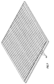
- FIG. 4 is a top view of an embodiment of the polarized gas separator of the present invention wherein the porous conductive substrate is corrugated.
- FIG. 5 is an exploded view of an embodiment of a fuel cell assembly of the present invention.
- FIG. 6 is an edge-on view of an embodiment of the polarized gas separator of the present invention wherein the porous conductive substrate is continuously-folded.
- FIG. 7 is a top view of an embodiment of the polarized gas separator of the present invention wherein the porous conductive substrate is continuously-folded.
- FIG. 8 is an edge-on view of an embodiment of the polarized gas separator of the present invention wherein the porous conductive substrate is discontinuously-folded.
- FIG. 9 is a top view of an embodiment of the present invention wherein the porous conductive substrate is discontinuously-folded.
- FIG. 3 Shown generally at 300 in FIG. 3 is an edge-on view of one embodiment of the polarized gas separator of the present invention. Shown in FIG. 3 are the primary components of the polarized gas separator, porous conductive substrate 302 , and barrier layer 304 .
- Porous conductive substrate 302 is essentially a flow field that, in this particular embodiment, has rounded corrugations created by peaks and troughs in the flow field.
- a corrugated porous conductive substrate is one configuration of the porous conductive substrate that enables the polarized gas separator to be suitable for bipolar construction of a fuel cell stack assembly.
- the rounded corrugations have a pitch and a run that are defined by the peaks and the troughs of the corrugations.
- FIG. 4 illustrates these microchannels at 402 . If used in conjunction with the distribution frame described in Pat. No. 6,531,238 and shown generally at 500 in FIG. 5, these microchannels run parallel to the air inlet 502 and the air and water outlet and perpendicular to fuel inlets 504 . Because the microchannels run parallel to the air and water outlet, the microchannels can effectively remove the water from the anode side flow field and the cathode side flow field out air and water outlet 506 .
- This corrugated configuration for the porous conductive substrate provides for effective management of the liquid-phase water in the anode side, previously unaddressed by conventional bipolar plate assemblies. It also provides for effective water management in the cathode side flow field.
- barrier layer 304 laterally spans porous conductive substrate 302 and effectively bisects it so that a portion of porous conductive substrate 302 extends from the top side of barrier layer 304 and a second portion of porous conductive substrate 302 extends from the bottom side of barrier layer 304 .
- the bisected portions of the porous conductive substrate extending from the barrier layer may or may not be equal in size. Preferably, however, the bisected portions should be approximately equal in size, or one side may be approximately half the size of the other side if the smaller side is used as the anode side.
- the barrier layer material effectively and completely fills the porous holes of porous conductive substrate 302 to prevent the passage of the gas reactants through the barrier layer but does not destroy the integrity of porous conductive substrate 302 .
- Continuous electrical conductivity is maintained through porous conductive substrate 302 on both sides of barrier layer 304 despite the presence of barrier layer 304 because the electrical conductivity of the porous conductive substrate is not interrupted by barrier layer 304 .
- the holes in the porous conductive substrate at the intersections between the porous conductive substrate and the barrier layer are full of the barrier material, and therefore, the reactant gases cannot pass through the barrier; but the electrical connections between the anode side and the cathode side of the porous conductive substrate are continuous because there is no interruption in the flow field despite the presence of barrier layer 304 . Gases cannot penetrate barrier layer 304 , and therefore, the reactant gases are effectively sealed from one another; however, because of the porosity and surface texture of porous conductive substrate 302 , the reactant gases can move relatively freely within the two flow fields themselves that are formed by barrier layer 304 , and are able to diffuse to the respective catalytic active layers of the membrane electrode assembly (“MEA”) effectively.
- MEA membrane electrode assembly
- barrier layer 304 may act as an insulator, and depending on the particular construction material used for barrier layer 304 , the barrier layer may in fact enhance the electrical continuity of the porous conductive substrate because it has no electrical properties of its own that detract from the electrical continuity within the flow field.
- the structure of the polarized gas separator of the present invention requires no mechanical bonding mechanism, and therefore, electrical continuity is enhanced because resistance is not introduced via a bonding mechanism. Further, there are no air gaps in the connections between the flow fields and the barrier, as is often the case in conventional bipolar assemblies that would ordinarily create added resistance. A substantial reduction in disruptive electrical resistance is achieved as a result of this design.
- Barrier layer 304 can be comprised of any thermal setting nonconductive thermoplastic that has sufficient insulating properties.
- barrier layer 304 is a thermal setting epoxy or an epoxy derivative. Epoxy is preferred because of its good insulating properties and because of its suitable lack of electrical properties.
- the materials used as or to form barrier layer 304 should have no porosity and, preferably, should be completely dense. Most preferably, barrier layer 304 should be a monolithic layer.
- barrier layer 304 may be formed by a hardened formerly fluid composition such as a thermosetting thermoplastic; it is also contemplated that barrier layer 304 may be formed by a material that is able to completely seal the two portions of the flow field when used in its original form as long as it is able to bisect the porous conductive substrate, seal the reactant gases from each other effectively, and fill the holes in the porous conductive substrate at the intersections between the substrate and the barrier layer without disturbing the electrical properties of the porous conductive substrate.
- the preferable thickness of barrier layer 304 is about 1 ⁇ 4 of the height or pitch of porous conductive substrate 302 .
- this thickness may vary, one must be conscious of the potential for voids in the barrier layer if it is made too thin. Also, thicker barriers may lead to a loss in area in the flow field—a loss in area in a flow field could possibly lead to problems in distributing the reactants to their designated catalytic active layers.
- Porous conductive substrate 302 can be made from a variety of different materials that may be, in turn, comprised of a variety of construction materials that may take on a variety of different configurations as illustrated in FIGS. 3, 6 , and 8 .
- the materials that can be used as the porous conductive substrate include, but are not limited to: metal wool; wire mesh; three-dimensional open-cell foamed structures suitable for gas diffusion (as described in Pat. No. 6,531,238, the disclosure of which is hereby incorporated by reference); and aerated nickel wool.
- the two main criteria that are useful in choosing which particular material is suitable for porous conductive substrate 302 are: (1) sufficient porosity, and (2) adequate surface textures.
- 6,531,238 may be particularly suitable as porous conductive substrate 302 as this material has sufficient porosity and surface texture, and is well-suited to gas diffusion. As described in Pat. No. 6,531,238, these three-dimensional open-cell foams may be produced by electroplating nickel over a particulate plastic structure so that the voids created by the tangential intersections in the particulate plastic structure are filled with nickel. Although polystyrene may be used in this method, other materials, such as other particulate thermoplastic materials, would be suitable. Isinglass is one example.
- the polystyrene particulate matter may be blown out of the formed foam with hot carbon dioxide gas or air to leave a three-dimensional nickel open-cell foamed flow field having substantially five-sided, geometrically-shaped orifices.
- the pitch of the corrugations be equal to about five to six times the thickness of the material that forms the substrate, and the run of the corrugations be equal to about two to three times the thickness of the material.
- the number of peaks and troughs is dictated by the total length of the flow field based on these parameters. Of course, these specifications may be varied if suitable for the intended use.
- the advantage obtained from utilizing a three-dimensional open-cell foamed flow field in the present invention is that mass transfer within the resultant flow fields is enhanced. This is because the mass transfer rate is supplemented by the foamed flow field itself and its wicking ability, which allows the molecules to electromosatically move through the flow field.
- Another advantage associated with the foamed flow fields over conventional serpentine arrangements is that they facilitate the deposit of the reactants uniformly along the surfaces of the catalytic active layers.
- Suitable construction materials for the above materials possess good electrical conductivity properties are conducive to flow distribution and include, but are not limited to: hastelloys, inconel, nickel, copper, conductive plastics, metal composites, plastic composites, tin oxides, gold, epitaxial substrates, stainless steel, and their derivatives. Iridium may also be used if it has sufficient electrical properties.
- Stainless steel 416 does not appear to be suitable at this time because of the potential for staining; staining is undesirable. If, for example, a plating technique or some other technique were developed that combated the potential for stainless steel 416 to stain, then it would be a suitable construction material.
- Other construction materials may be suitable as well.
- Another specific example of a suitable material of construction is a plastic material having sufficient porosity wherein carbon fibers have been imbedded so that it also has sufficient electrical properties.
- porous conductive substrate Suitable configurations for the porous conductive substrate include but are not limited to: corrugated (as shown in FIG. 3 ), continuously-folded (as shown in FIG. 6 ), and discontinuously-folded (as shown in FIG. 8 ). Although these three seem especially suitable configurations for the porous conductive substrate of the polarized gas separator, other configurations that may or may not be variations of these, are also contemplated within the present invention.
- FIG. 6 depicts an edge-on view of an alternative embodiment of the polarized gas separator having a corrugated porous conductive substrate of the present invention wherein the porous conductive substrate is a continuously-folded porous conductive substrate.
- the continuously-folded porous conductive substrate embodiment of the present invention may be an improvement over the corrugated embodiment having rounded peaks in some instances as a result of the substantially flat top surfaces and bottom surfaces of the resultant corrugations or folds that provide a larger contact area with the contiguous layers of the fuel cell assembly.
- the continuously-folded embodiment is another version of a corrugated flow field wherein the peaks created by the peaks and troughs are square rather than rounded.
- the peaks and troughs in the continuously-folded substrate have a pitch and a run that are defined by the substantially flat top surfaces, the substantially flat bottom surfaces, and the substantially vertical portions of the corrugations in the continuously-folded substrate.
- the vertical portion of the folds should be substantially perpendicular and connected to the top and bottom surfaces.
- the pitch is equal to about five to six times the thickness of the material used to form the porous conductive substrate.
- the run which is the length of the horizontal top or bottom surface of an individual fold, is equal to about two to three times the thickness of the material used to form porous conductive metal substrate 12 .
- FIG. 8 depicts another alternative embodiment of the polarized gas separator of the present invention wherein a discontinuously-folded porous conductive substrate is used.
- the discontinuously-folded configuration is made up of independent pods 802 formed from a chosen material that is porous and conductive. The same materials and construction materials discussed above for the corrugated embodiment may also be used in this embodiment. Additionally, each pod can be constructed from the same or a different material, and the same or a different construction material.
- the pods are concentrically folded and arranged along a horizontal axis defined by barrier layer 804 .
- the pods have a pitch and a run that are defined by the length of the horizontal top and bottom surfaces of each pod and the height of that pod.
- the pitch is equal to about five to six times the thickness of the material used to form the individual pod, and the run is equal to about two to three times the thickness of the material used to form the pod.
- the spacing between the independent pods can vary from no spacing between the pods to as much as desired. Preferably, however, the spacing between the pods ranges from 2 to 6 times the thickness of one of the construction materials used to form one of the pods. This spacing can be guided by the desired width of the resultant microchannels created in the flow field as shown in FIG. 9 at 901 . Of course, these specifications may be varied to optimize the system for an intended use. For example, one pod can be formed from a wire mesh made from nickel while another pod is formed from a stainless steel wool.
- the number of pods needed is dictated by the length of the flow field and the above criteria. If the pods are concentrically folded, they should include an outside layer and at least one internal layer formed from concentrically folding the porous conductive substrate. More folds may be appropriate in a given application, however.
- the empty space created between the layers by the concentric folds is preferably twice the thickness of the substrate used for the pod.
- Microchannels are created in the flow fields between the individual pods that facilitate the removal of heat and water from the fuel cell assembly as shown in FIG. 9 at 901 .
- the discontinuously-folded embodiment may also be particularly advantageous as a result of the increased surface area on the horizontal top and bottom surfaces that contact the next contiguous layer in the fuel cell; however, it may be more expensive to manufacture than the other embodiments.
- One method of manufacturing the polarized gas separator of the present invention involves shrinking a thermal setting epoxy around the porous metal substrate so that a first portion of the porous conductive substrate extends upward from the top surface of the epoxy barrier layer and a second portion of the porous conductive substrate extends from the bottom surface of the epoxy barrier layer.
- the method involves providing a porous conductive substrate, providing a mold, placing the porous conductive substrate in the mold, adding a thermal setting epoxy to the mold containing the porous conductive substrate, adding a hardener to the thermal setting epoxy in the mold to cause the epoxy to harden and shrink to form the barrier that bisects the porous conductive substrate to form a polarized gas separator, and then removing the resultant polarized gas separator from the mold. Enhancements to this method are contemplated within the present invention.
- the polarized gas separators of the present invention may be used in conjunction with conventional distribution frames like those illustrated in FIG. 2, they are preferably and effectively used in conjunction with the fuel cell stack assemblies and distribution frames disclosed in Pat. No. 6,531,238.
- the polarized gas separator of the present invention provides an enhancement to the fuel cell stack assemblies described in Pat. No. 6,531,238 the disclosure of which is incorporated herein by reference.
- the polarized gas separator of the present invention can be used at 508 and 510 in conjunction with the distribution frame to help facilitate transportation of the fuel and the oxidant to the fuel cell necessary for the electrochemical exchange.
- FIG. 5 the polarized gas separator of the present invention provides an enhancement to the fuel cell stack assemblies described in Pat. No. 6,531,238 the disclosure of which is incorporated herein by reference.
- the polarized gas separator of the present invention can be used at 508 and 510 in conjunction with the distribution frame to help facilitate transportation of the fuel and the oxidant to the fuel cell necessary for the electrochemical exchange.
- FIG. 5 depicts the components of a fuel cell assembly of one embodiment of the present invention, namely, distribution frame 500 , primary polarized gas separator 508 , MEA 512 , and secondary polarized gas separator 510 .
- Primary polarized gas separator 508 consists of primary anode flow field formed from the lateral spansion of the barrier layer and the secondary cathode flow field also formed from the spansion of the barrier layer.
- MEA 512 is composed of an electrolyte and two catalytic active layers, one for the anode and one for the cathode. Any known MEAs are suitable in the present invention.
- the procession of contiguous layers in the fuel cell assembly is: primary anode gas flow field (from polarized gas separator 508 ), barrier layer (from polarized gas separator 508 ), primary cathode flow field (from polarized gas separator 508 ), MEA 512 , secondary anode flow field (from polarized gas separator 510 ), barrier layer (from polarized gas separator 510 ), and secondary cathode flow field (from polarized gas separator 510 ).
- Fuel inlets 504 and air inlet 502 on the distribution frame provide the reactants to the respective flow fields. Specifically, fuel inlet 502 provides fuel to the secondary anode flow field (as part of polarized gas separator 510 ).
- Fuel supply channels stretch from the interior sides or surfaces of the fuel inlets to supply the fuel to the flow fields. Air is fed to the cathode flow fields through air supply channels that are integral to the air inlet of the distribution frame. Two or more of these individual fuel cell assemblies can be combined to form a node. Two or more nodes can be combined to form a fuel cell stack assembly. Typically, these individual fuel cells will be interposed between end plates, which are preferably circular members, to form stacks or nodes. Stacks can be placed in series to increase voltage to a desired level, or such stacks can be arranged in parallel to increase amperes. In one embodiment of the present invention, one end plate is used for every six fuel cell assemblies to provide desirable and enhanced torsional properties to the stack assembly.
- a coalescer on the anode side and/or a coalescer on the cathode side may be used between the respective anode and cathode catalytic active layers of the MEA and the respective anode and cathode flow fields of the polarized gas separators.
- An anode side coalescer aids in the removal of the liquid-phase water, a by-product of humidification, in the anode flow field from the face of the anode catalytic active layer of the MEA and its ultimate removal from the fuel cell. Removing this water increases the diffusion rate within the anode flow field of the reactant to the catalytic active layer.
- a cathode side coalescer aids in the management of the free water in the cathode flow field formed as a by-product of the electrochemical exchange.
- the water vapor or fine mist coalesces When used in conjunction with one of the polarized gas separators described herein, at each coalescer, the water vapor or fine mist coalesces and is quickly converted to larger droplets that are removed from the flow fields by the coalescer and microchannel combination (the microchannels being formed by the configuration of the porous conductive substrate as described above and depicted in FIGS. 4, 7 , and 9 ).
- Suitable materials for either coalescer include but are not limited to fibrous materials, that can be either woven or nonwoven. Suitable woven materials include cotton muslin or linen.
- Nonwoven materials are also suitable if they have sufficient coalescing properties. Their coalescing properties may be enhanced by treating the surface of the nonwoven with a known stamping or -punching technique.
- the construction materials for a woven or a nonwoven anode side coalescer should be hydrophilic; the construction materials for a woven or a nonwoven cathode side coalescer should be more hydrophobic than those used for an anode side coalescer.
Abstract
Description
Claims (36)
Priority Applications (4)
| Application Number | Priority Date | Filing Date | Title |
|---|---|---|---|
| US09/740,423 US6656624B1 (en) | 2000-09-26 | 2000-12-19 | Polarized gas separator and liquid coalescer for fuel cell stack assemblies |
| PCT/US2001/042031 WO2002027815A2 (en) | 2000-09-26 | 2001-09-06 | Polarized gas separator and liquid coalescer for fuel cell stack assemblies |
| EP01973696A EP1504480A2 (en) | 2000-09-26 | 2001-09-06 | Polarized gas separator and liquid coalescer for fuel cell stack assemblies |
| AU2001293249A AU2001293249A1 (en) | 2000-09-26 | 2001-09-06 | Polarized gas separator and liquid coalescer for fuel cell stack assemblies |
Applications Claiming Priority (2)
| Application Number | Priority Date | Filing Date | Title |
|---|---|---|---|
| US09/669,344 US6531238B1 (en) | 2000-09-26 | 2000-09-26 | Mass transport for ternary reaction optimization in a proton exchange membrane fuel cell assembly and stack assembly |
| US09/740,423 US6656624B1 (en) | 2000-09-26 | 2000-12-19 | Polarized gas separator and liquid coalescer for fuel cell stack assemblies |
Related Parent Applications (1)
| Application Number | Title | Priority Date | Filing Date |
|---|---|---|---|
| US09/669,344 Continuation-In-Part US6531238B1 (en) | 2000-09-26 | 2000-09-26 | Mass transport for ternary reaction optimization in a proton exchange membrane fuel cell assembly and stack assembly |
Publications (1)
| Publication Number | Publication Date |
|---|---|
| US6656624B1 true US6656624B1 (en) | 2003-12-02 |
Family
ID=24685995
Family Applications (6)
| Application Number | Title | Priority Date | Filing Date |
|---|---|---|---|
| US09/669,344 Expired - Fee Related US6531238B1 (en) | 2000-09-26 | 2000-09-26 | Mass transport for ternary reaction optimization in a proton exchange membrane fuel cell assembly and stack assembly |
| US09/711,197 Expired - Fee Related US6582842B1 (en) | 2000-09-26 | 2000-11-09 | Enhancement of proton exchange membrane fuel cell system by use of radial placement and integrated structural support system |
| US09/740,423 Expired - Fee Related US6656624B1 (en) | 2000-09-26 | 2000-12-19 | Polarized gas separator and liquid coalescer for fuel cell stack assemblies |
| US10/267,559 Expired - Fee Related US7005210B2 (en) | 2000-09-26 | 2002-10-09 | Flow fields for fuel cells |
| US10/267,310 Abandoned US20040048138A1 (en) | 2000-09-26 | 2002-10-09 | Distribution frame for a fuel cell |
| US10/267,321 Expired - Fee Related US6951698B2 (en) | 2000-09-26 | 2002-10-09 | Fuel cell stack assembly |
Family Applications Before (2)
| Application Number | Title | Priority Date | Filing Date |
|---|---|---|---|
| US09/669,344 Expired - Fee Related US6531238B1 (en) | 2000-09-26 | 2000-09-26 | Mass transport for ternary reaction optimization in a proton exchange membrane fuel cell assembly and stack assembly |
| US09/711,197 Expired - Fee Related US6582842B1 (en) | 2000-09-26 | 2000-11-09 | Enhancement of proton exchange membrane fuel cell system by use of radial placement and integrated structural support system |
Family Applications After (3)
| Application Number | Title | Priority Date | Filing Date |
|---|---|---|---|
| US10/267,559 Expired - Fee Related US7005210B2 (en) | 2000-09-26 | 2002-10-09 | Flow fields for fuel cells |
| US10/267,310 Abandoned US20040048138A1 (en) | 2000-09-26 | 2002-10-09 | Distribution frame for a fuel cell |
| US10/267,321 Expired - Fee Related US6951698B2 (en) | 2000-09-26 | 2002-10-09 | Fuel cell stack assembly |
Country Status (4)
| Country | Link |
|---|---|
| US (6) | US6531238B1 (en) |
| EP (1) | EP1481435A2 (en) |
| AU (1) | AU2001287096A1 (en) |
| WO (1) | WO2002027838A2 (en) |
Cited By (13)
| Publication number | Priority date | Publication date | Assignee | Title |
|---|---|---|---|---|
| US20040028988A1 (en) * | 2002-08-06 | 2004-02-12 | General Electric Company | Fiber cooling of fuel cells |
| US20040048140A1 (en) * | 2000-09-26 | 2004-03-11 | Reliant Energy Power Systems, Inc. | Flow fields for fuel cells |
| WO2007038132A1 (en) * | 2005-09-21 | 2007-04-05 | Jones Eric T | Fuel cell device |
| US20080113254A1 (en) * | 2006-09-07 | 2008-05-15 | Andrew Leigh Christie | Apparatus and method for managing fluids in a fuel cell stack |
| US20090325025A1 (en) * | 2007-04-02 | 2009-12-31 | Gm Global Technology Operations, Inc. | Hydrophilic and corrosion resistant fuel cell components |
| US20100129733A1 (en) * | 2007-04-02 | 2010-05-27 | Staxera Gmbh | Interconnector arrangement and method for producing a contact arrangement for a fuel cell stack |
| US20100180427A1 (en) * | 2009-01-16 | 2010-07-22 | Ford Motor Company | Texturing of thin metal sheets/foils for enhanced formability and manufacturability |
| US20100248043A1 (en) * | 2009-03-31 | 2010-09-30 | Ise Corporation | Hydrogen Fuel Cell Water Knock Out Device and Method of Use |
| US20100285386A1 (en) * | 2009-05-08 | 2010-11-11 | Treadstone Technologies, Inc. | High power fuel stacks using metal separator plates |
| US20100330389A1 (en) * | 2009-06-25 | 2010-12-30 | Ford Motor Company | Skin pass for cladding thin metal sheets |
| US8003274B2 (en) | 2007-10-25 | 2011-08-23 | Relion, Inc. | Direct liquid fuel cell |
| US8026020B2 (en) | 2007-05-08 | 2011-09-27 | Relion, Inc. | Proton exchange membrane fuel cell stack and fuel cell stack module |
| US9293778B2 (en) | 2007-06-11 | 2016-03-22 | Emergent Power Inc. | Proton exchange membrane fuel cell |
Families Citing this family (81)
| Publication number | Priority date | Publication date | Assignee | Title |
|---|---|---|---|---|
| US20020022170A1 (en) * | 2000-08-18 | 2002-02-21 | Franklin Jerrold E. | Integrated and modular BSP/MEA/manifold plates for fuel cells |
| US20050202296A1 (en) * | 2001-02-15 | 2005-09-15 | Integral Technologies, Inc. | Low cost fuel cell bipolar plates manufactured from conductive loaded resin-based materials |
| JP4058666B2 (en) * | 2001-08-16 | 2008-03-12 | ソニー株式会社 | Fuel cell |
| US6716549B2 (en) | 2001-12-27 | 2004-04-06 | Avista Laboratories, Inc. | Fuel cell having metalized gas diffusion layer |
| DE60300904T2 (en) * | 2002-03-27 | 2005-12-22 | Haldor Topsoe A/S | Solid oxide fuel cell in thin-film technology (SOFC) and process for its production |
| US6866958B2 (en) * | 2002-06-05 | 2005-03-15 | General Motors Corporation | Ultra-low loadings of Au for stainless steel bipolar plates |
| US20040001993A1 (en) * | 2002-06-28 | 2004-01-01 | Kinkelaar Mark R. | Gas diffusion layer for fuel cells |
| US20040001991A1 (en) * | 2002-07-01 | 2004-01-01 | Kinkelaar Mark R. | Capillarity structures for water and/or fuel management in fuel cells |
| JP4003942B2 (en) * | 2002-08-06 | 2007-11-07 | 本田技研工業株式会社 | Fuel cell separator and fuel cell |
| WO2004023588A1 (en) * | 2002-09-06 | 2004-03-18 | Richards Engineering | Modular fuel cell |
| US7001687B1 (en) * | 2002-10-04 | 2006-02-21 | The Texas A&M University System | Unitized MEA assemblies and methods for making same |
| US7005209B1 (en) * | 2002-10-04 | 2006-02-28 | The Texas A&M University System | Fuel cell stack assembly |
| US7163761B2 (en) * | 2002-11-14 | 2007-01-16 | 3M Innovative Properties Company | Fuel cell stack |
| CA2506173C (en) * | 2002-11-15 | 2011-10-11 | Sprint Communications Company L.P. | Proton exchange membrane based power system for a telecommunication facility |
| US6960838B2 (en) * | 2002-11-15 | 2005-11-01 | Sprint Communications Company L.P. | Power system for a telecommunication facility |
| AU2003297783A1 (en) * | 2002-12-27 | 2004-07-29 | Foamex L.P. | Gas diffusion layer containing inherently conductive polymer for fuel cells |
| US7056608B2 (en) | 2003-02-14 | 2006-06-06 | Relion, Inc. | Current collector for use in a fuel cell |
| US6939636B2 (en) * | 2003-04-28 | 2005-09-06 | Relion, Inc. | Air cooled fuel cell module |
| US7308510B2 (en) * | 2003-05-07 | 2007-12-11 | Intel Corporation | Method and apparatus for avoiding live-lock in a multinode system |
| EP1627444A2 (en) * | 2003-05-09 | 2006-02-22 | Foamex L.P. | Gas diffusion layer having carbon particle mixture |
| US7670707B2 (en) | 2003-07-30 | 2010-03-02 | Altergy Systems, Inc. | Electrical contacts for fuel cells |
| US20050100774A1 (en) * | 2003-11-07 | 2005-05-12 | Abd Elhamid Mahmoud H. | Novel electrical contact element for a fuel cell |
| RU2256981C1 (en) * | 2004-03-30 | 2005-07-20 | Общество с ограниченной ответственностью "ИНТЕНСИС" (ООО "ИНТЕНСИС") | Alkali fuel cell electrode and its manufacturing process |
| US8249952B2 (en) * | 2004-03-31 | 2012-08-21 | Jda Software Group, Inc. | Incorporating a repair vendor into repair planning for a supply chain |
| US8566181B2 (en) * | 2004-03-31 | 2013-10-22 | Jda Software Group, Inc. | Incorporating a repair vendor into repair planning for supply chain |
| US8090630B2 (en) * | 2004-03-31 | 2012-01-03 | Jda Software Group, Inc. | Planning a supply of items to a first location associated with a supply chain from one or more second locations associated with the supply chain |
| CN1938888A (en) * | 2004-04-19 | 2007-03-28 | Lg电子株式会社 | Fuel cell |
| JP5043291B2 (en) * | 2004-06-30 | 2012-10-10 | キヤノン株式会社 | Combustible substance blocking device and fuel cell |
| US7240492B2 (en) * | 2004-07-22 | 2007-07-10 | Sprint Communications Company L.P. | Fuel system used for cooling purposes |
| US7081687B2 (en) * | 2004-07-22 | 2006-07-25 | Sprint Communications Company L.P. | Power system for a telecommunications facility |
| US7323270B2 (en) * | 2004-08-11 | 2008-01-29 | Fuelcell Energy, Inc. | Modular fuel-cell stack assembly |
| FR2875340B1 (en) * | 2004-09-14 | 2006-11-17 | Renault Sas | DEVICE AND METHOD FOR MANAGING POWER SUPPLIES OF A FUEL CELL |
| JP2006095007A (en) * | 2004-09-29 | 2006-04-13 | Funai Electric Co Ltd | Charging type moving system |
| JP4692001B2 (en) * | 2005-02-08 | 2011-06-01 | トヨタ自動車株式会社 | Fuel cell separator |
| US8048576B2 (en) | 2005-07-12 | 2011-11-01 | Honeywell International Inc. | Power generator shut-off valve |
| US20070072050A1 (en) * | 2005-08-26 | 2007-03-29 | Canon Kabushiki Kaisha | Fuel cell |
| US7727655B2 (en) * | 2005-10-25 | 2010-06-01 | Honeywell International Inc. | Fuel cell stack having catalyst coated proton exchange member |
| US7811690B2 (en) * | 2005-10-25 | 2010-10-12 | Honeywell International Inc. | Proton exchange membrane fuel cell |
| US20080032174A1 (en) * | 2005-11-21 | 2008-02-07 | Relion, Inc. | Proton exchange membrane fuel cells and electrodes |
| US7833645B2 (en) * | 2005-11-21 | 2010-11-16 | Relion, Inc. | Proton exchange membrane fuel cell and method of forming a fuel cell |
| US20070122667A1 (en) * | 2005-11-28 | 2007-05-31 | Kelley Richard H | Fuel cell system with integrated fuel processor |
| US7557531B2 (en) * | 2005-12-19 | 2009-07-07 | Sprint Communications Company L.P. | Power system utilizing flow batteries |
| US7728458B2 (en) | 2006-01-05 | 2010-06-01 | Sprint Communications Company L.P. | Telecommunications megasite with backup power system |
| US8043736B2 (en) * | 2006-01-10 | 2011-10-25 | Honeywell International Inc. | Power generator having multiple layers of fuel cells |
| US7659022B2 (en) | 2006-08-14 | 2010-02-09 | Modine Manufacturing Company | Integrated solid oxide fuel cell and fuel processor |
| WO2007087305A2 (en) * | 2006-01-23 | 2007-08-02 | Bloom Energy Corporation | Integrated solid oxide fuel cell and fuel processor |
| EP1982364A4 (en) | 2006-01-23 | 2010-07-07 | Bloom Energy Corp | Modular fuel cell system |
| US20070178340A1 (en) * | 2006-01-31 | 2007-08-02 | Honeywell International Inc. | Fuel cell power generator with micro turbine |
| US8241801B2 (en) * | 2006-08-14 | 2012-08-14 | Modine Manufacturing Company | Integrated solid oxide fuel cell and fuel processor |
| US8283079B2 (en) * | 2006-11-03 | 2012-10-09 | Honeywell International Inc. | Fuel cell power generator with water reservoir |
| US8822097B2 (en) | 2006-11-30 | 2014-09-02 | Honeywell International Inc. | Slide valve for fuel cell power generator |
| JP5125435B2 (en) * | 2006-12-13 | 2013-01-23 | 三菱マテリアル株式会社 | Porous titanium with low contact resistance |
| US20080248358A1 (en) * | 2007-01-23 | 2008-10-09 | Canon Kabushiki Kaisha | Polymer electrolyte fuel cell and production method thereof |
| US8409758B2 (en) * | 2007-04-17 | 2013-04-02 | Modine Manufacturing Company | Fuel cell system with partial external reforming and direct internal reforming |
| WO2008131078A1 (en) * | 2007-04-17 | 2008-10-30 | Modine Manufacaturing Company | Solid oxide fuel cell unit for use in distributed power generation |
| US8137741B2 (en) * | 2007-05-10 | 2012-03-20 | Fuelcell Energy, Inc. | System for fabricating a fuel cell component for use with or as part of a fuel cell in a fuel cell stack |
| US8920997B2 (en) * | 2007-07-26 | 2014-12-30 | Bloom Energy Corporation | Hybrid fuel heat exchanger—pre-reformer in SOFC systems |
| US20090035625A1 (en) * | 2007-08-01 | 2009-02-05 | Tihiro Ohkawa | Hydrogen fuel cell with integrated reformer |
| US8852820B2 (en) | 2007-08-15 | 2014-10-07 | Bloom Energy Corporation | Fuel cell stack module shell with integrated heat exchanger |
| EP2045861B1 (en) * | 2007-10-05 | 2012-03-14 | Topsøe Fuel Cell A/S | Seal for porous metal support in a fuel cell |
| FR2923086B1 (en) * | 2007-10-24 | 2010-12-10 | Commissariat Energie Atomique | INTEGRATED COMBUSTIBLE CELL ARCHITECTURE WITHOUT SEAL. |
| WO2009105191A2 (en) | 2008-02-19 | 2009-08-27 | Bloom Energy Corporation | Fuel cell system containing anode tail gas oxidizer and hybrid heat exchanger/reformer |
| US8968958B2 (en) * | 2008-07-08 | 2015-03-03 | Bloom Energy Corporation | Voltage lead jumper connected fuel cell columns |
| US8932738B2 (en) * | 2008-10-16 | 2015-01-13 | Institute Of Nuclear Energy Research | Fuel cell assembly structure |
| US20110306261A1 (en) * | 2009-02-25 | 2011-12-15 | Basf Se | Method for producing flexible metal contacts |
| US20100297535A1 (en) * | 2009-05-20 | 2010-11-25 | Das Susanta K | Novel design of fuel cell bipolar for optimal uniform delivery of reactant gases and efficient water removal |
| US8623565B2 (en) * | 2009-05-20 | 2014-01-07 | Susanta K. Das | Assembly of bifurcation and trifurcation bipolar plate to design fuel cell stack |
| DE102010003643A1 (en) * | 2010-04-01 | 2011-10-06 | Forschungszentrum Jülich GmbH | fuel cell module |
| US8440362B2 (en) | 2010-09-24 | 2013-05-14 | Bloom Energy Corporation | Fuel cell mechanical components |
| JP6258037B2 (en) | 2011-01-06 | 2018-01-10 | ブルーム エナジー コーポレーション | Components of SOFC hot box |
| FR2977727B1 (en) * | 2011-07-08 | 2014-02-28 | Helion | FUEL CELL WITH IMPROVED FLUID SUPPLY CIRCUIT, AND METHOD FOR MANUFACTURING SUCH FUEL CELL |
| GB2505693A (en) * | 2012-09-07 | 2014-03-12 | Univ Dublin City | A proton exchange membrane fuel cell with open pore cellular foam |
| BR112015011332A2 (en) | 2012-11-19 | 2017-07-11 | Sandvik Intellectual Property | drill and screwdriver, and method for preoperative assessment of bone quality |
| FR3000108B1 (en) | 2012-12-21 | 2015-02-27 | Commissariat Energie Atomique | ELECTRICAL INSULATION AND SEALING FRAME FOR WATER ELECTROLYSIS REACTOR (SOEC) OR FUEL CELL (SOFC). |
| US9755263B2 (en) | 2013-03-15 | 2017-09-05 | Bloom Energy Corporation | Fuel cell mechanical components |
| US9287572B2 (en) | 2013-10-23 | 2016-03-15 | Bloom Energy Corporation | Pre-reformer for selective reformation of higher hydrocarbons |
| US9461320B2 (en) | 2014-02-12 | 2016-10-04 | Bloom Energy Corporation | Structure and method for fuel cell system where multiple fuel cells and power electronics feed loads in parallel allowing for integrated electrochemical impedance spectroscopy (EIS) |
| US10651496B2 (en) | 2015-03-06 | 2020-05-12 | Bloom Energy Corporation | Modular pad for a fuel cell system |
| US11398634B2 (en) | 2018-03-27 | 2022-07-26 | Bloom Energy Corporation | Solid oxide fuel cell system and method of operating the same using peak shaving gas |
| EP4220785A2 (en) * | 2019-07-16 | 2023-08-02 | CH Innovations Inc. | Compact fuel cell modules and assemblies |
| CN115332552B (en) * | 2022-10-14 | 2022-12-20 | 上海治臻新能源股份有限公司 | Conductive precoat for fuel cell titanium polar plate and preparation method thereof |
Citations (135)
| Publication number | Priority date | Publication date | Assignee | Title |
|---|---|---|---|---|
| US2008800A (en) * | 1933-08-23 | 1935-07-23 | Herbert J Somers | Filter |
| US3432357A (en) * | 1964-09-28 | 1969-03-11 | Gen Electric | Fluent material distribution system and fuel cell therewith |
| US3615862A (en) | 1967-02-20 | 1971-10-26 | United Aircraft Corp | Fuel cell electrodes |
| US3616841A (en) | 1967-10-30 | 1971-11-02 | Energy Research And Generation | Method of making an inorganic reticulated foam structure |
| US3617385A (en) * | 1969-03-13 | 1971-11-02 | Texas Instruments Inc | Fuel cell |
| US3772086A (en) | 1972-07-17 | 1973-11-13 | Gen Electric | Method of making anodes for hydrazine fuel cells |
| US3960601A (en) | 1974-09-27 | 1976-06-01 | Union Carbide Corporation | Fuel cell electrode |
| US4044193A (en) | 1971-06-16 | 1977-08-23 | Prototech Company | Finely particulated colloidal platinum compound and sol for producing the same, and method of preparation of fuel cell electrodes and the like employing the same |
| US4058482A (en) | 1976-12-20 | 1977-11-15 | United Technologies Corporation | Fuel cell electrode |
| US4125676A (en) | 1977-08-15 | 1978-11-14 | United Technologies Corp. | Carbon foam fuel cell components |
| US4131721A (en) | 1977-06-17 | 1978-12-26 | Electric Power Research Institute, Inc. | Electrolytic cell having a novel electrode including platinum on a carbon support activated with a phosphorus-oxygen-containing compound |
| US4168351A (en) | 1978-02-10 | 1979-09-18 | P. R. Mallory & Co., Inc. | Stabilized glass-to-metal seals in lithium cell environments |
| US4175165A (en) | 1977-07-20 | 1979-11-20 | Engelhard Minerals & Chemicals Corporation | Fuel cell system utilizing ion exchange membranes and bipolar plates |
| US4192907A (en) | 1978-07-03 | 1980-03-11 | United Technologies Corporation | Electrochemical cell electrodes incorporating noble metal-base metal alloy catalysts |
| US4356240A (en) | 1980-10-27 | 1982-10-26 | Duracell Inc. | Extremely high rate flat cell |
| US4365007A (en) * | 1981-06-12 | 1982-12-21 | Energy Research Corporation | Fuel cell with internal reforming |
| US4372759A (en) | 1981-08-28 | 1983-02-08 | United Technologies Corporation | Electrolyte vapor condenser |
| US4390446A (en) | 1981-05-13 | 1983-06-28 | Duracell Inc. | Solid state cell with anolyte |
| US4396480A (en) | 1982-02-02 | 1983-08-02 | W. R. Grace & Co. | Solid electrolyte sheet |
| US4413041A (en) | 1982-02-02 | 1983-11-01 | W. R. Grace & Co. | Cross-flow monolith reactor |
| US4458411A (en) | 1980-10-27 | 1984-07-10 | Duracell Inc. | Method of fabricating an extremely high rate flat cell |
| US4463065A (en) | 1982-02-02 | 1984-07-31 | W. R. Grace & Co. | Fuel cell and method for conducting gas-phase oxidation |
| US4496437A (en) | 1983-06-22 | 1985-01-29 | The Dow Chemical Company | Method for producing a dual porosity body |
| US4525440A (en) | 1981-05-13 | 1985-06-25 | Duracell Inc. | Solid state cell with anolyte |
| US4529677A (en) | 1982-02-02 | 1985-07-16 | Texon Incorporated | Battery separator material |
| US4556613A (en) | 1979-07-03 | 1985-12-03 | Duracell Inc. | Resistant glass in glass-metal seal and cell terminal structure for lithium electrochemical cells |
| USH16H (en) | 1984-03-02 | 1986-01-07 | The United States Of America As Represented By The United States Department Of Energy | Fuel cell electrode and method of preparation |
| US4735872A (en) | 1986-11-18 | 1988-04-05 | The United States Of America As Represented By The United States Department Of Energy | Electrochemical system including lamella settler crystallizer |
| US4769297A (en) | 1987-11-16 | 1988-09-06 | International Fuel Cells Corporation | Solid polymer electrolyte fuel cell stack water management system |
| US4800138A (en) | 1987-04-16 | 1989-01-24 | International Fuel Cells Corporation | Separation of gaseous hydrogen from a water-hydrogen mixture in a fuel cell power system operating in a weightless environment |
| US4818741A (en) | 1986-11-20 | 1989-04-04 | Electric Power Research Institute, Inc. | Porous and porous-nonporous composites for battery electrodes |
| US4876115A (en) | 1987-01-30 | 1989-10-24 | United States Department Of Energy | Electrode assembly for use in a solid polymer electrolyte fuel cell |
| USRE33149E (en) | 1971-06-16 | 1990-01-16 | Prototech Company | Finely particulated colloidal platinum compound and sol for producing the same and method of preparation of fuel cell electrodes and the like employing the same |
| US4910099A (en) | 1988-12-05 | 1990-03-20 | The United States Of America As Represented By The United States Department Of Energy | Preventing CO poisoning in fuel cells |
| US4910106A (en) | 1988-08-05 | 1990-03-20 | Hoechst Celanese Corporation | Formation of halogenated polymeric microporous membranes having improved strength properties |
| US4925749A (en) | 1987-12-24 | 1990-05-15 | Lilliwyte Societe Anonyme | Electrochemical cell |
| US4973532A (en) | 1989-04-05 | 1990-11-27 | Hoechst Celanese Corporation | Battery separator with integral thermal fuse |
| US4973358A (en) | 1989-09-06 | 1990-11-27 | Alcan International Limited | Method of producing lightweight foamed metal |
| US4988583A (en) | 1989-08-30 | 1991-01-29 | Her Majesty The Queen As Represented By The Minister Of National Defence Of Her Majesty's Canadian Government | Novel fuel cell fluid flow field plate |
| US5008163A (en) | 1989-05-26 | 1991-04-16 | The United States Of America As Represented By The United States Department Of Energy | Conductive ceramic composition and method of preparation |
| US5013618A (en) | 1989-09-05 | 1991-05-07 | International Fuel Cells Corporation | Ternary alloy fuel cell catalysts and phosphoric acid fuel cell containing the catalysts |
| US5068161A (en) | 1990-03-30 | 1991-11-26 | Johnson Matthey Public Limited Company | Catalyst material |
| US5071717A (en) | 1988-09-08 | 1991-12-10 | International Fuel Cells Corporation | Coated cathode substrate |
| US5079105A (en) | 1989-05-18 | 1992-01-07 | Asea Brown Boveri Ltd. | Device for conversion of chemical energy from hydrocarbons into electric energy by an electrochemical high-temperature process |
| US5108849A (en) | 1989-08-30 | 1992-04-28 | Her Majesty The Queen In Right Of Canada, As Represented By The Minister Of National Defence In Her Britannic Majesty's Government Of The United Kingdom Of Great Britain And Northern Ireland | Fuel cell fluid flow field plate |
| US5110692A (en) * | 1990-08-20 | 1992-05-05 | Energy Research Corporation | Gasket for molten carbonate fuel cell |
| US5139896A (en) | 1989-05-26 | 1992-08-18 | The United States Of America As Represented By The United States Department Of Energy | All ceramic structure for molten carbonate fuel cell |
| US5242764A (en) | 1991-12-17 | 1993-09-07 | Bcs Technology, Inc. | Near ambient, unhumidified solid polymer fuel cell |
| US5264299A (en) | 1991-12-26 | 1993-11-23 | International Fuel Cells Corporation | Proton exchange membrane fuel cell support plate and an assembly including the same |
| US5316747A (en) | 1992-10-09 | 1994-05-31 | Ballard Power Systems Inc. | Method and apparatus for the selective oxidation of carbon monoxide in a hydrogen-containing gas mixture |
| US5318863A (en) | 1991-12-17 | 1994-06-07 | Bcs Technology, Inc. | Near ambient, unhumidified solid polymer fuel cell |
| US5344724A (en) | 1992-04-10 | 1994-09-06 | Matsushita Electric Industrial Co., Ltd. | Non-aqueous electrolyte secondary cell |
| US5360679A (en) | 1993-08-20 | 1994-11-01 | Ballard Power Systems Inc. | Hydrocarbon fueled solid polymer fuel cell electric power generation system |
| US5364712A (en) | 1992-02-21 | 1994-11-15 | Hughes Aircraft Company | Dual porosity gas evolving electrode |
| US5366821A (en) | 1992-03-13 | 1994-11-22 | Ballard Power Systems Inc. | Constant voltage fuel cell with improved reactant supply and control system |
| US5366819A (en) | 1993-10-06 | 1994-11-22 | Ceramatec, Inc. | Thermally integrated reformer for solid oxide fuel cells |
| US5418079A (en) | 1993-07-20 | 1995-05-23 | Sulzer Innotec Ag | Axially symmetric fuel cell battery |
| US5432021A (en) | 1992-10-09 | 1995-07-11 | Ballard Power Systems Inc. | Method and apparatus for oxidizing carbon monoxide in the reactant stream of an electrochemical fuel cell |
| US5434020A (en) | 1993-11-15 | 1995-07-18 | The Regents Of The University Of California | Continuous-feed electrochemical cell with nonpacking particulate electrode |
| US5441819A (en) | 1991-01-15 | 1995-08-15 | Ballard Power Systems Inc. | Method and apparatus for removing water from electrochemical fuel cells by controlling the temperature and pressure of the reactant streams |
| US5441821A (en) | 1994-12-23 | 1995-08-15 | Ballard Power Systems Inc. | Electrochemical fuel cell system with a regulated vacuum ejector for recirculation of the fluid fuel stream |
| US5482792A (en) | 1993-04-30 | 1996-01-09 | De Nora Permelec S.P.A. | Electrochemical cell provided with ion exchange membranes and bipolar metal plates |
| US5482680A (en) | 1992-10-09 | 1996-01-09 | Ballard Power Systems, Inc. | Electrochemical fuel cell assembly with integral selective oxidizer |
| US5503944A (en) | 1995-06-30 | 1996-04-02 | International Fuel Cells Corp. | Water management system for solid polymer electrolyte fuel cell power plants |
| EP0709907A1 (en) | 1994-10-21 | 1996-05-01 | Canon Kabushiki Kaisha | An anode with anode active material retaining body having a number of pores distributed therein for a rechargeable battery, rechargeable battery provided with said anode, and process for the production of said anode |
| US5518831A (en) | 1995-07-07 | 1996-05-21 | The Dow Chemical Company | Electrocatalytic structure |
| US5521018A (en) | 1993-12-10 | 1996-05-28 | Ballard Power Systems Inc. | Embossed fluid flow field plate for electrochemical fuel cells |
| WO1996020509A1 (en) | 1994-12-27 | 1996-07-04 | Ballard Power Systems Inc. | Integrated external manifold assembly for an electrochemical fuel cell stack array |
| US5547776A (en) | 1991-01-15 | 1996-08-20 | Ballard Power Systems Inc. | Electrochemical fuel cell stack with concurrently flowing coolant and oxidant streams |
| US5589285A (en) | 1993-09-09 | 1996-12-31 | Technology Management, Inc. | Electrochemical apparatus and process |
| US5599638A (en) | 1993-10-12 | 1997-02-04 | California Institute Of Technology | Aqueous liquid feed organic fuel cell using solid polymer electrolyte membrane |
| US5604057A (en) | 1995-11-27 | 1997-02-18 | General Motors Corporation | Secondary cell having a lithium intercolating manganese oxide |
| US5607770A (en) | 1985-10-22 | 1997-03-04 | Ucar Carbon Technology Corporation | Carbon-carbon composites containing poorly graphitizing pitch as a binder and/or impregnant having a reduced coefficient of thermal expansion and improved flexural strength |
| US5624769A (en) | 1995-12-22 | 1997-04-29 | General Motors Corporation | Corrosion resistant PEM fuel cell |
| WO1997024474A1 (en) | 1995-12-29 | 1997-07-10 | Chloralp | Asbestos-free cathodic element suitable for electrolysis of sodium chloride solution |
| US5660941A (en) | 1996-06-19 | 1997-08-26 | Energy Research Corporation | Catalyst assembly for internal reforming fuel cell |
| US5683828A (en) | 1994-10-12 | 1997-11-04 | H Power Corp. | Metal platelet fuel cells production and operation methods |
| US5707755A (en) | 1996-12-09 | 1998-01-13 | General Motors Corporation | PEM/SPE fuel cell |
| US5763114A (en) | 1994-09-01 | 1998-06-09 | Gas Research Institute | Integrated reformer/CPN SOFC stack module design |
| US5773162A (en) | 1993-10-12 | 1998-06-30 | California Institute Of Technology | Direct methanol feed fuel cell and system |
| US5776624A (en) | 1996-12-23 | 1998-07-07 | General Motors Corporation | Brazed bipolar plates for PEM fuel cells |
| US5776625A (en) | 1997-06-18 | 1998-07-07 | H Power Corporation | Hydrogen-air fuel cell |
| US5827495A (en) | 1995-10-03 | 1998-10-27 | Kabushiki Kaisha Toshiba | Molten carbonate fuel cell and method of manufacturing retaining material for electrolyte body of molten carbonate fuel cell |
| US5848351A (en) * | 1995-04-03 | 1998-12-08 | Mitsubishi Materials Corporation | Porous metallic material having high specific surface area, method of producing the same, porous metallic plate material and electrode for alkaline secondary battery |
| US5853910A (en) | 1996-03-29 | 1998-12-29 | Kabushikikaisha Equos Research | Fuel cell power generating apparatus and operation method therefor |
| US5863671A (en) | 1994-10-12 | 1999-01-26 | H Power Corporation | Plastic platelet fuel cells employing integrated fluid management |
| US5879826A (en) | 1995-07-05 | 1999-03-09 | Humboldt State University Foundation | Proton exchange membrane fuel cell |
| US6007932A (en) | 1996-10-16 | 1999-12-28 | Gore Enterprise Holdings, Inc. | Tubular fuel cell assembly and method of manufacture |
| US6017650A (en) | 1997-04-18 | 2000-01-25 | De Nora S.P.A. | Gas-diffussion electrodes for polymeric membrane fuel cell |
| US6020083A (en) | 1998-10-30 | 2000-02-01 | International Fuel Cells Llc | Membrane electrode assembly for PEM fuel cell |
| US6022634A (en) | 1996-06-26 | 2000-02-08 | De Nora S.P.A. | Membrane electrochemical cell provided with gas diffusion electrodes in contact with porour, flat, metal current conductors having highly distributed contact area |
| US6033804A (en) | 1996-11-01 | 2000-03-07 | E. I. Du Pont De Nemours And Company | Highly conductive ion exchange polymer and process |
| US6051117A (en) | 1996-12-12 | 2000-04-18 | Eltech Systems, Corp. | Reticulated metal article combining small pores with large apertures |
| US6074692A (en) | 1998-04-10 | 2000-06-13 | General Motors Corporation | Method of making MEA for PEM/SPE fuel cell |
| US6096449A (en) | 1997-11-20 | 2000-08-01 | Avista Labs | Fuel cell and method for controlling same |
| US6096450A (en) | 1998-02-11 | 2000-08-01 | Plug Power Inc. | Fuel cell assembly fluid flow plate having conductive fibers and rigidizing material therein |
| US6096448A (en) | 1997-12-23 | 2000-08-01 | Ballard Power Systems Inc. | Method and apparatus for operating an electrochemical fuel cell with periodic fuel starvation at the anode |
| US6099984A (en) | 1997-12-15 | 2000-08-08 | General Motors Corporation | Mirrored serpentine flow channels for fuel cell |
| US6103077A (en) | 1998-01-02 | 2000-08-15 | De Nora S.P.A. | Structures and methods of manufacture for gas diffusion electrodes and electrode components |
| US6106964A (en) | 1997-06-30 | 2000-08-22 | Ballard Power Systems Inc. | Solid polymer fuel cell system and method for humidifying and adjusting the temperature of a reactant stream |
| US6110333A (en) | 1997-05-02 | 2000-08-29 | E. I. Du Pont De Nemours And Company | Composite membrane with highly crystalline porous support |
| US6124053A (en) | 1998-07-09 | 2000-09-26 | Fuel Cell Technologies, Inc. | Fuel cell with internal combustion chamber |
| US6127056A (en) | 1998-10-09 | 2000-10-03 | International Fuel Cells, Llc | Start up of proton exchange membrane fuel cell |
| US6140266A (en) | 1999-02-18 | 2000-10-31 | International Fuel Cells, Co., Llc | Compact and light weight catalyst bed for use in a fuel cell power plant and method for forming the same |
| US6146780A (en) | 1997-01-24 | 2000-11-14 | Lynntech, Inc. | Bipolar separator plates for electrochemical cell stacks |
| US6150056A (en) * | 1997-05-30 | 2000-11-21 | Matsushita Electric Industrial Co., Ltd. | Alkaline storage battery and method for producing an electrode used therefor |
| WO2000072373A1 (en) | 1999-05-25 | 2000-11-30 | Forskarpatent I Uppsala Ab | Method for manufacturing nanostructured thin film electrodes |
| US6165633A (en) | 1996-03-26 | 2000-12-26 | Toyota Jidosha Kabushiki Kaisha | Method of and apparatus for reforming fuel and fuel cell system with fuel-reforming apparatus incorporated therein |
| US6197445B1 (en) | 1998-03-06 | 2001-03-06 | Rayovac Corporation | Air depolarized electrochemical cells |
| WO2001020702A2 (en) | 1999-09-13 | 2001-03-22 | Ballard Generation Systems Inc. | Fuel cell electric power generation system |
| US6207309B1 (en) | 1999-07-16 | 2001-03-27 | International Fuel Cells Llc | Environmental compensation method and apparatus for a fuel cell assembly |
| US6207308B1 (en) | 1999-04-20 | 2001-03-27 | International Fuel Cells, Llc | Water treatment system for a fuel cell assembly |
| US6210820B1 (en) | 1998-07-02 | 2001-04-03 | Ballard Power Systems Inc. | Method for operating fuel cells on impure fuels |
| WO2001025140A1 (en) | 1999-10-05 | 2001-04-12 | Ballard Power Systems Inc. | Fuel cell power generation system with autothermal reformer |
| US6218035B1 (en) | 1997-11-20 | 2001-04-17 | Avista Laboratories, Inc. | Proton exchange membrane fuel cell power system |
| US6232010B1 (en) | 1999-05-08 | 2001-05-15 | Lynn Tech Power Systems, Ltd. | Unitized barrier and flow control device for electrochemical reactors |
| US6232008B1 (en) | 1997-07-16 | 2001-05-15 | Ballard Power Systems Inc. | Electrochemical fuel cell stack with improved reactant manifolding and sealing |
| US6238817B1 (en) | 1999-02-03 | 2001-05-29 | International Fuel Cells, Llc | Gas injection system for treating a fuel cell stack assembly |
| US6242118B1 (en) | 1999-10-14 | 2001-06-05 | International Fuel Cells Llc | Method and apparatus for removing contaminants from the coolant supply of a fuel cell power plant |
| US6248462B1 (en) | 1999-05-28 | 2001-06-19 | International Fuel Cells, Llc | Method and apparatus for thermal management of a fuel cell assembly |
| US6268076B1 (en) | 1997-02-15 | 2001-07-31 | Forschungszentrum Jülich GmbH | Current collector for a SOFC fuel-cell pile |
| US6277508B1 (en) | 1998-07-17 | 2001-08-21 | International Fuel Cells Corporation | Fuel cell power supply with exhaust recycling for improved water management |
| US6280870B1 (en) | 1999-08-26 | 2001-08-28 | Plug Power Inc. | Combined fuel cell flow plate and gas diffusion layer |
| US6284399B1 (en) | 1999-09-17 | 2001-09-04 | Plug Power Llc | Fuel cell system having humidification membranes |
| US20010031389A1 (en) | 2000-02-11 | 2001-10-18 | The Texas A&M University System | Gas diffusion electrode with nanosized pores and method for making same |
| US6331366B1 (en) | 1999-06-23 | 2001-12-18 | International Fuel Cells Llc | Operating system for a fuel cell power plant |
| US6372376B1 (en) | 1999-12-07 | 2002-04-16 | General Motors Corporation | Corrosion resistant PEM fuel cell |
| US6387557B1 (en) | 1998-10-21 | 2002-05-14 | Utc Fuel Cells, Llc | Bonded fuel cell stack assemblies |
| US6387556B1 (en) | 1997-11-20 | 2002-05-14 | Avista Laboratories, Inc. | Fuel cell power systems and methods of controlling a fuel cell power system |
| US6399234B2 (en) | 1998-12-23 | 2002-06-04 | Utc Fuel Cells, Llc | Fuel cell stack assembly with edge seal |
| US20020068208A1 (en) | 2000-09-28 | 2002-06-06 | Dristy Mark E. | Cell frame/flow field integration method and apparatus |
| US6403249B1 (en) | 2000-01-12 | 2002-06-11 | Humboldt State University Foundation | Humidification of a PEM fuel cell by air-air moisture exchange |
| US6410180B1 (en) | 1996-06-06 | 2002-06-25 | Lynntech, Inc. | Fuel cell system for low pressure operation |
| US6413664B1 (en) | 1999-12-23 | 2002-07-02 | Ballard Power Systems Inc. | Fuel cell separator plate with discrete fluid distribution features |
| DE19812155C2 (en) | 1998-03-20 | 2002-11-14 | Forschungszentrum Juelich Gmbh | Arrangement for energy conversion, comprising at least two fuel cell stacks and at least one reformer unit, and a use of the arrangement |
Family Cites Families (38)
| Publication number | Priority date | Publication date | Assignee | Title |
|---|---|---|---|---|
| FR1593242A (en) * | 1968-03-19 | 1970-05-25 | ||
| FR2125159B1 (en) * | 1971-02-15 | 1973-11-30 | Alsthom Cgee | |
| US4108756A (en) | 1973-10-30 | 1978-08-22 | Oronzio De Nora Impianti Electtrochimici S.P.A. | Bipolar electrode construction |
| US4124478A (en) * | 1977-02-07 | 1978-11-07 | Tsien Hsue C | Thin sheet apparatus and a fluid flow device |
| US4214969A (en) * | 1979-01-02 | 1980-07-29 | General Electric Company | Low cost bipolar current collector-separator for electrochemical cells |
| SE418508B (en) * | 1979-04-20 | 1981-06-09 | Svenska Utvecklings Ab | ELECTRICAL PACKAGE PROVIDED TO BE USED IN A CELL, WHICH AN ELECTROCHEMICAL REACTION IS CARRIED OUT AND USED BY THE SAME IN A MEMBRAN CELL IN AN ELECTROLYSOR CELL OF FILTER PRESSURE TYPE |
| FR2558485B1 (en) | 1984-01-25 | 1990-07-13 | Rech Applic Electrochimique | POROUS METAL STRUCTURE, MANUFACTURING METHOD THEREOF AND APPLICATIONS |
| US4588661A (en) * | 1984-08-27 | 1986-05-13 | Engelhard Corporation | Fabrication of gas impervious edge seal for a bipolar gas distribution assembly for use in a fuel cell |
| FR2579025B1 (en) * | 1985-03-15 | 1987-04-10 | Occidental Chem Co | IMPROVED SEPARATION FUEL CELL |
| JPS63232275A (en) | 1987-03-20 | 1988-09-28 | Mitsubishi Electric Corp | Fuel cell of lamination type |
| JPH04141233A (en) | 1990-09-29 | 1992-05-14 | Stonehard Assoc Inc | Electrode catalyst |
| JPH04237962A (en) * | 1991-01-18 | 1992-08-26 | Matsushita Electric Ind Co Ltd | Flat type solid electrolyte fuel cell |
| JPH0541239A (en) | 1991-06-18 | 1993-02-19 | Nkk Corp | High temperature type fuel cell module |
| JPH05262902A (en) | 1992-03-23 | 1993-10-12 | Tanaka Kikinzoku Kogyo Kk | Preparation of ion-exchange membrane |
| US5189005A (en) | 1992-04-03 | 1993-02-23 | Tanaka Kikinzoku Kogyo K.K. | Electrocatalyst and process of preparing same |
| US5300370A (en) | 1992-11-13 | 1994-04-05 | Ballard Power Systems Inc. | Laminated fluid flow field assembly for electrochemical fuel cells |
| NL9401159A (en) * | 1994-07-13 | 1996-02-01 | Stork Screens Bv | Foam product. |
| US5514487A (en) | 1994-12-27 | 1996-05-07 | Ballard Power Systems Inc. | Edge manifold assembly for an electrochemical fuel cell stack |
| US5939025A (en) | 1995-08-23 | 1999-08-17 | The University Of Chicago | Methanol partial oxidation reformer |
| DE19542475C2 (en) | 1995-11-15 | 1999-10-28 | Ballard Power Systems | Polymer electrolyte membrane fuel cell and method for producing a distributor plate for such a cell |
| US5672439A (en) | 1995-12-18 | 1997-09-30 | Ballard Power Systems, Inc. | Method and apparatus for reducing reactant crossover in an electrochemical fuel cell |
| US5863673A (en) | 1995-12-18 | 1999-01-26 | Ballard Power Systems Inc. | Porous electrode substrate for an electrochemical fuel cell |
| US5858314A (en) | 1996-04-12 | 1999-01-12 | Ztek Corporation | Thermally enhanced compact reformer |
| US6033793A (en) | 1996-11-01 | 2000-03-07 | Hydrogen Burner Technology, Inc. | Integrated power module |
| US5789091C1 (en) | 1996-11-19 | 2001-02-27 | Ballard Power Systems | Electrochemical fuel cell stack with compression bands |
| US5804326A (en) | 1996-12-20 | 1998-09-08 | Ballard Power Systems Inc. | Integrated reactant and coolant fluid flow field layer for an electrochemical fuel cell |
| AU5547698A (en) * | 1997-02-11 | 1998-08-26 | Ulf G. Bossel | Fuel cell stack with solid electrolytes and their arrangement |
| JPH10242084A (en) | 1997-02-24 | 1998-09-11 | Lintec Corp | Wafer pasting adhesive sheet and manufacturing method of electronic components |
| US5942350A (en) * | 1997-03-10 | 1999-08-24 | United Technologies Corporation | Graded metal hardware component for an electrochemical cell |
| US5976726A (en) | 1997-05-01 | 1999-11-02 | Ballard Power Systems Inc. | Electrochemical cell with fluid distribution layer having integral sealing capability |
| FR2764443B1 (en) | 1997-06-10 | 1999-09-03 | Peugeot | FUEL CELL OF THE TYPE WITH PLATE-SHAPED REAGENT DISPENSERS |
| US6057053A (en) | 1997-11-25 | 2000-05-02 | Ballard Power Systems Inc. | Compression assembly for an electrochemical fuel cell stack |
| US5935726A (en) | 1997-12-01 | 1999-08-10 | Ballard Power Systems Inc. | Method and apparatus for distributing water to an ion-exchange membrane in a fuel cell |
| US6053266A (en) | 1997-12-01 | 2000-04-25 | Dbb Fuel Cell Engines Gmbh | Fuel cell engine having a propulsion motor operatively connected to drive a fluid supply device |
| US6063515A (en) | 1997-12-22 | 2000-05-16 | Ballard Power Systems Inc. | Integrated fuel cell electric power generation system for submarine applications |
| US6238819B1 (en) * | 1998-01-23 | 2001-05-29 | Stork, N.V. | Metal foam support, electrode and method of making same |
| ITMI991090A1 (en) * | 1999-05-18 | 2000-11-18 | De Nora Spa | HUMIDIFYING DEVICE FOR POLYMER MEMBRANE FUEL CELLS |
| US6531238B1 (en) * | 2000-09-26 | 2003-03-11 | Reliant Energy Power Systems, Inc. | Mass transport for ternary reaction optimization in a proton exchange membrane fuel cell assembly and stack assembly |
-
2000
- 2000-09-26 US US09/669,344 patent/US6531238B1/en not_active Expired - Fee Related
- 2000-11-09 US US09/711,197 patent/US6582842B1/en not_active Expired - Fee Related
- 2000-12-19 US US09/740,423 patent/US6656624B1/en not_active Expired - Fee Related
-
2001
- 2001-09-06 AU AU2001287096A patent/AU2001287096A1/en not_active Abandoned
- 2001-09-06 EP EP01966595A patent/EP1481435A2/en not_active Withdrawn
- 2001-09-06 WO PCT/US2001/027588 patent/WO2002027838A2/en active Application Filing
-
2002
- 2002-10-09 US US10/267,559 patent/US7005210B2/en not_active Expired - Fee Related
- 2002-10-09 US US10/267,310 patent/US20040048138A1/en not_active Abandoned
- 2002-10-09 US US10/267,321 patent/US6951698B2/en not_active Expired - Fee Related
Patent Citations (149)
| Publication number | Priority date | Publication date | Assignee | Title |
|---|---|---|---|---|
| US2008800A (en) * | 1933-08-23 | 1935-07-23 | Herbert J Somers | Filter |
| US3432357A (en) * | 1964-09-28 | 1969-03-11 | Gen Electric | Fluent material distribution system and fuel cell therewith |
| US3615862A (en) | 1967-02-20 | 1971-10-26 | United Aircraft Corp | Fuel cell electrodes |
| US3616841A (en) | 1967-10-30 | 1971-11-02 | Energy Research And Generation | Method of making an inorganic reticulated foam structure |
| US3617385A (en) * | 1969-03-13 | 1971-11-02 | Texas Instruments Inc | Fuel cell |
| USRE33149E (en) | 1971-06-16 | 1990-01-16 | Prototech Company | Finely particulated colloidal platinum compound and sol for producing the same and method of preparation of fuel cell electrodes and the like employing the same |
| US4044193A (en) | 1971-06-16 | 1977-08-23 | Prototech Company | Finely particulated colloidal platinum compound and sol for producing the same, and method of preparation of fuel cell electrodes and the like employing the same |
| US3772086A (en) | 1972-07-17 | 1973-11-13 | Gen Electric | Method of making anodes for hydrazine fuel cells |
| US3960601A (en) | 1974-09-27 | 1976-06-01 | Union Carbide Corporation | Fuel cell electrode |
| US4058482A (en) | 1976-12-20 | 1977-11-15 | United Technologies Corporation | Fuel cell electrode |
| US4131721A (en) | 1977-06-17 | 1978-12-26 | Electric Power Research Institute, Inc. | Electrolytic cell having a novel electrode including platinum on a carbon support activated with a phosphorus-oxygen-containing compound |
| US4175165A (en) | 1977-07-20 | 1979-11-20 | Engelhard Minerals & Chemicals Corporation | Fuel cell system utilizing ion exchange membranes and bipolar plates |
| US4125676A (en) | 1977-08-15 | 1978-11-14 | United Technologies Corp. | Carbon foam fuel cell components |
| US4168351A (en) | 1978-02-10 | 1979-09-18 | P. R. Mallory & Co., Inc. | Stabilized glass-to-metal seals in lithium cell environments |
| US4192907A (en) | 1978-07-03 | 1980-03-11 | United Technologies Corporation | Electrochemical cell electrodes incorporating noble metal-base metal alloy catalysts |
| US4556613A (en) | 1979-07-03 | 1985-12-03 | Duracell Inc. | Resistant glass in glass-metal seal and cell terminal structure for lithium electrochemical cells |
| US4356240A (en) | 1980-10-27 | 1982-10-26 | Duracell Inc. | Extremely high rate flat cell |
| US4458411A (en) | 1980-10-27 | 1984-07-10 | Duracell Inc. | Method of fabricating an extremely high rate flat cell |
| US4525440A (en) | 1981-05-13 | 1985-06-25 | Duracell Inc. | Solid state cell with anolyte |
| US4390446A (en) | 1981-05-13 | 1983-06-28 | Duracell Inc. | Solid state cell with anolyte |
| US4365007A (en) * | 1981-06-12 | 1982-12-21 | Energy Research Corporation | Fuel cell with internal reforming |
| US4372759A (en) | 1981-08-28 | 1983-02-08 | United Technologies Corporation | Electrolyte vapor condenser |
| US4413041A (en) | 1982-02-02 | 1983-11-01 | W. R. Grace & Co. | Cross-flow monolith reactor |
| US4396480A (en) | 1982-02-02 | 1983-08-02 | W. R. Grace & Co. | Solid electrolyte sheet |
| US4463065A (en) | 1982-02-02 | 1984-07-31 | W. R. Grace & Co. | Fuel cell and method for conducting gas-phase oxidation |
| US4529677A (en) | 1982-02-02 | 1985-07-16 | Texon Incorporated | Battery separator material |
| US4496437A (en) | 1983-06-22 | 1985-01-29 | The Dow Chemical Company | Method for producing a dual porosity body |
| USH16H (en) | 1984-03-02 | 1986-01-07 | The United States Of America As Represented By The United States Department Of Energy | Fuel cell electrode and method of preparation |
| US5607770A (en) | 1985-10-22 | 1997-03-04 | Ucar Carbon Technology Corporation | Carbon-carbon composites containing poorly graphitizing pitch as a binder and/or impregnant having a reduced coefficient of thermal expansion and improved flexural strength |
| US4735872A (en) | 1986-11-18 | 1988-04-05 | The United States Of America As Represented By The United States Department Of Energy | Electrochemical system including lamella settler crystallizer |
| US4818741A (en) | 1986-11-20 | 1989-04-04 | Electric Power Research Institute, Inc. | Porous and porous-nonporous composites for battery electrodes |
| US4876115A (en) | 1987-01-30 | 1989-10-24 | United States Department Of Energy | Electrode assembly for use in a solid polymer electrolyte fuel cell |
| US4800138A (en) | 1987-04-16 | 1989-01-24 | International Fuel Cells Corporation | Separation of gaseous hydrogen from a water-hydrogen mixture in a fuel cell power system operating in a weightless environment |
| US4769297A (en) | 1987-11-16 | 1988-09-06 | International Fuel Cells Corporation | Solid polymer electrolyte fuel cell stack water management system |
| US4925749A (en) | 1987-12-24 | 1990-05-15 | Lilliwyte Societe Anonyme | Electrochemical cell |
| US4910106A (en) | 1988-08-05 | 1990-03-20 | Hoechst Celanese Corporation | Formation of halogenated polymeric microporous membranes having improved strength properties |
| US5071717A (en) | 1988-09-08 | 1991-12-10 | International Fuel Cells Corporation | Coated cathode substrate |
| US4910099A (en) | 1988-12-05 | 1990-03-20 | The United States Of America As Represented By The United States Department Of Energy | Preventing CO poisoning in fuel cells |
| US4973532A (en) | 1989-04-05 | 1990-11-27 | Hoechst Celanese Corporation | Battery separator with integral thermal fuse |
| US5079105A (en) | 1989-05-18 | 1992-01-07 | Asea Brown Boveri Ltd. | Device for conversion of chemical energy from hydrocarbons into electric energy by an electrochemical high-temperature process |
| US5139896A (en) | 1989-05-26 | 1992-08-18 | The United States Of America As Represented By The United States Department Of Energy | All ceramic structure for molten carbonate fuel cell |
| US5008163A (en) | 1989-05-26 | 1991-04-16 | The United States Of America As Represented By The United States Department Of Energy | Conductive ceramic composition and method of preparation |
| US4988583A (en) | 1989-08-30 | 1991-01-29 | Her Majesty The Queen As Represented By The Minister Of National Defence Of Her Majesty's Canadian Government | Novel fuel cell fluid flow field plate |
| US5108849A (en) | 1989-08-30 | 1992-04-28 | Her Majesty The Queen In Right Of Canada, As Represented By The Minister Of National Defence In Her Britannic Majesty's Government Of The United Kingdom Of Great Britain And Northern Ireland | Fuel cell fluid flow field plate |
| US5013618A (en) | 1989-09-05 | 1991-05-07 | International Fuel Cells Corporation | Ternary alloy fuel cell catalysts and phosphoric acid fuel cell containing the catalysts |
| US4973358A (en) | 1989-09-06 | 1990-11-27 | Alcan International Limited | Method of producing lightweight foamed metal |
| US5068161A (en) | 1990-03-30 | 1991-11-26 | Johnson Matthey Public Limited Company | Catalyst material |
| US5110692A (en) * | 1990-08-20 | 1992-05-05 | Energy Research Corporation | Gasket for molten carbonate fuel cell |
| US5547776A (en) | 1991-01-15 | 1996-08-20 | Ballard Power Systems Inc. | Electrochemical fuel cell stack with concurrently flowing coolant and oxidant streams |
| US5441819A (en) | 1991-01-15 | 1995-08-15 | Ballard Power Systems Inc. | Method and apparatus for removing water from electrochemical fuel cells by controlling the temperature and pressure of the reactant streams |
| US5242764A (en) | 1991-12-17 | 1993-09-07 | Bcs Technology, Inc. | Near ambient, unhumidified solid polymer fuel cell |
| US5318863A (en) | 1991-12-17 | 1994-06-07 | Bcs Technology, Inc. | Near ambient, unhumidified solid polymer fuel cell |
| US5264299A (en) | 1991-12-26 | 1993-11-23 | International Fuel Cells Corporation | Proton exchange membrane fuel cell support plate and an assembly including the same |
| US5364712A (en) | 1992-02-21 | 1994-11-15 | Hughes Aircraft Company | Dual porosity gas evolving electrode |
| US5366821A (en) | 1992-03-13 | 1994-11-22 | Ballard Power Systems Inc. | Constant voltage fuel cell with improved reactant supply and control system |
| US5344724A (en) | 1992-04-10 | 1994-09-06 | Matsushita Electric Industrial Co., Ltd. | Non-aqueous electrolyte secondary cell |
| US5482680A (en) | 1992-10-09 | 1996-01-09 | Ballard Power Systems, Inc. | Electrochemical fuel cell assembly with integral selective oxidizer |
| US5432021A (en) | 1992-10-09 | 1995-07-11 | Ballard Power Systems Inc. | Method and apparatus for oxidizing carbon monoxide in the reactant stream of an electrochemical fuel cell |
| US5316747A (en) | 1992-10-09 | 1994-05-31 | Ballard Power Systems Inc. | Method and apparatus for the selective oxidation of carbon monoxide in a hydrogen-containing gas mixture |
| US5482792A (en) | 1993-04-30 | 1996-01-09 | De Nora Permelec S.P.A. | Electrochemical cell provided with ion exchange membranes and bipolar metal plates |
| US5578388A (en) | 1993-04-30 | 1996-11-26 | De Nora Permelec S.P.A. | Electrochemical cell provided with ion exchange membranes and bipolar metal plates |
| US5565072A (en) | 1993-04-30 | 1996-10-15 | De Nora Permelec S.P.A. | Electrochemical cell provided with ion exchange membranes and bipolar metal plates |
| US5418079A (en) | 1993-07-20 | 1995-05-23 | Sulzer Innotec Ag | Axially symmetric fuel cell battery |
| US5360679A (en) | 1993-08-20 | 1994-11-01 | Ballard Power Systems Inc. | Hydrocarbon fueled solid polymer fuel cell electric power generation system |
| US5589285A (en) | 1993-09-09 | 1996-12-31 | Technology Management, Inc. | Electrochemical apparatus and process |
| US5366819A (en) | 1993-10-06 | 1994-11-22 | Ceramatec, Inc. | Thermally integrated reformer for solid oxide fuel cells |
| US5599638A (en) | 1993-10-12 | 1997-02-04 | California Institute Of Technology | Aqueous liquid feed organic fuel cell using solid polymer electrolyte membrane |
| US5773162A (en) | 1993-10-12 | 1998-06-30 | California Institute Of Technology | Direct methanol feed fuel cell and system |
| US6303244B1 (en) | 1993-10-12 | 2001-10-16 | California Institute Of Technology | Direct methanol feed fuel cell and system |
| US6265093B1 (en) | 1993-10-12 | 2001-07-24 | California Institute Of Technology | Direct methanol feed fuel cell and system |
| US6146781A (en) | 1993-10-12 | 2000-11-14 | California Institute Of Technology | Direct methanol feed fuel cell and system |
| US5434020A (en) | 1993-11-15 | 1995-07-18 | The Regents Of The University Of California | Continuous-feed electrochemical cell with nonpacking particulate electrode |
| US5521018A (en) | 1993-12-10 | 1996-05-28 | Ballard Power Systems Inc. | Embossed fluid flow field plate for electrochemical fuel cells |
| US5527363A (en) | 1993-12-10 | 1996-06-18 | Ballard Power Systems Inc. | Method of fabricating an embossed fluid flow field plate |
| US5763114A (en) | 1994-09-01 | 1998-06-09 | Gas Research Institute | Integrated reformer/CPN SOFC stack module design |
| US6051331A (en) | 1994-10-12 | 2000-04-18 | H Power Corporation | Fuel cell platelet separators having coordinate features |
| US5683828A (en) | 1994-10-12 | 1997-11-04 | H Power Corp. | Metal platelet fuel cells production and operation methods |
| US5863671A (en) | 1994-10-12 | 1999-01-26 | H Power Corporation | Plastic platelet fuel cells employing integrated fluid management |
| US5858567A (en) | 1994-10-12 | 1999-01-12 | H Power Corporation | Fuel cells employing integrated fluid management platelet technology |
| EP0709907A1 (en) | 1994-10-21 | 1996-05-01 | Canon Kabushiki Kaisha | An anode with anode active material retaining body having a number of pores distributed therein for a rechargeable battery, rechargeable battery provided with said anode, and process for the production of said anode |
| US5441821A (en) | 1994-12-23 | 1995-08-15 | Ballard Power Systems Inc. | Electrochemical fuel cell system with a regulated vacuum ejector for recirculation of the fluid fuel stream |
| WO1996020509A1 (en) | 1994-12-27 | 1996-07-04 | Ballard Power Systems Inc. | Integrated external manifold assembly for an electrochemical fuel cell stack array |
| US5848351A (en) * | 1995-04-03 | 1998-12-08 | Mitsubishi Materials Corporation | Porous metallic material having high specific surface area, method of producing the same, porous metallic plate material and electrode for alkaline secondary battery |
| US5503944A (en) | 1995-06-30 | 1996-04-02 | International Fuel Cells Corp. | Water management system for solid polymer electrolyte fuel cell power plants |
| US5879826A (en) | 1995-07-05 | 1999-03-09 | Humboldt State University Foundation | Proton exchange membrane fuel cell |
| US5518831A (en) | 1995-07-07 | 1996-05-21 | The Dow Chemical Company | Electrocatalytic structure |
| US6037076A (en) | 1995-10-03 | 2000-03-14 | Kabushiki Kaisha Toshiba | Molten carbonate fuel cell and method of manufacturing retaining material for electrolyte body of molten carbonate fuel cell |
| US5827495A (en) | 1995-10-03 | 1998-10-27 | Kabushiki Kaisha Toshiba | Molten carbonate fuel cell and method of manufacturing retaining material for electrolyte body of molten carbonate fuel cell |
| US5674644A (en) | 1995-11-27 | 1997-10-07 | General Motors Corporation | Manganese oxide electrode and method |
| US5604057A (en) | 1995-11-27 | 1997-02-18 | General Motors Corporation | Secondary cell having a lithium intercolating manganese oxide |
| US5624769A (en) | 1995-12-22 | 1997-04-29 | General Motors Corporation | Corrosion resistant PEM fuel cell |
| WO1997024474A1 (en) | 1995-12-29 | 1997-07-10 | Chloralp | Asbestos-free cathodic element suitable for electrolysis of sodium chloride solution |
| US6165633A (en) | 1996-03-26 | 2000-12-26 | Toyota Jidosha Kabushiki Kaisha | Method of and apparatus for reforming fuel and fuel cell system with fuel-reforming apparatus incorporated therein |
| US5853910A (en) | 1996-03-29 | 1998-12-29 | Kabushikikaisha Equos Research | Fuel cell power generating apparatus and operation method therefor |
| US6410180B1 (en) | 1996-06-06 | 2002-06-25 | Lynntech, Inc. | Fuel cell system for low pressure operation |
| US5660941A (en) | 1996-06-19 | 1997-08-26 | Energy Research Corporation | Catalyst assembly for internal reforming fuel cell |
| US6022634A (en) | 1996-06-26 | 2000-02-08 | De Nora S.P.A. | Membrane electrochemical cell provided with gas diffusion electrodes in contact with porour, flat, metal current conductors having highly distributed contact area |
| US6007932A (en) | 1996-10-16 | 1999-12-28 | Gore Enterprise Holdings, Inc. | Tubular fuel cell assembly and method of manufacture |
| US6033804A (en) | 1996-11-01 | 2000-03-07 | E. I. Du Pont De Nemours And Company | Highly conductive ion exchange polymer and process |
| US5707755A (en) | 1996-12-09 | 1998-01-13 | General Motors Corporation | PEM/SPE fuel cell |
| US6051117A (en) | 1996-12-12 | 2000-04-18 | Eltech Systems, Corp. | Reticulated metal article combining small pores with large apertures |
| US5776624A (en) | 1996-12-23 | 1998-07-07 | General Motors Corporation | Brazed bipolar plates for PEM fuel cells |
| US6146780A (en) | 1997-01-24 | 2000-11-14 | Lynntech, Inc. | Bipolar separator plates for electrochemical cell stacks |
| US6268076B1 (en) | 1997-02-15 | 2001-07-31 | Forschungszentrum Jülich GmbH | Current collector for a SOFC fuel-cell pile |
| US6017650A (en) | 1997-04-18 | 2000-01-25 | De Nora S.P.A. | Gas-diffussion electrodes for polymeric membrane fuel cell |
| US6110333A (en) | 1997-05-02 | 2000-08-29 | E. I. Du Pont De Nemours And Company | Composite membrane with highly crystalline porous support |
| US6150056A (en) * | 1997-05-30 | 2000-11-21 | Matsushita Electric Industrial Co., Ltd. | Alkaline storage battery and method for producing an electrode used therefor |
| US5776625A (en) | 1997-06-18 | 1998-07-07 | H Power Corporation | Hydrogen-air fuel cell |
| US6106964A (en) | 1997-06-30 | 2000-08-22 | Ballard Power Systems Inc. | Solid polymer fuel cell system and method for humidifying and adjusting the temperature of a reactant stream |
| US6232008B1 (en) | 1997-07-16 | 2001-05-15 | Ballard Power Systems Inc. | Electrochemical fuel cell stack with improved reactant manifolding and sealing |
| US6387556B1 (en) | 1997-11-20 | 2002-05-14 | Avista Laboratories, Inc. | Fuel cell power systems and methods of controlling a fuel cell power system |
| US6218035B1 (en) | 1997-11-20 | 2001-04-17 | Avista Laboratories, Inc. | Proton exchange membrane fuel cell power system |
| US6096449A (en) | 1997-11-20 | 2000-08-01 | Avista Labs | Fuel cell and method for controlling same |
| US6099984A (en) | 1997-12-15 | 2000-08-08 | General Motors Corporation | Mirrored serpentine flow channels for fuel cell |
| US6096448A (en) | 1997-12-23 | 2000-08-01 | Ballard Power Systems Inc. | Method and apparatus for operating an electrochemical fuel cell with periodic fuel starvation at the anode |
| US6103077A (en) | 1998-01-02 | 2000-08-15 | De Nora S.P.A. | Structures and methods of manufacture for gas diffusion electrodes and electrode components |
| US6096450A (en) | 1998-02-11 | 2000-08-01 | Plug Power Inc. | Fuel cell assembly fluid flow plate having conductive fibers and rigidizing material therein |
| US6197445B1 (en) | 1998-03-06 | 2001-03-06 | Rayovac Corporation | Air depolarized electrochemical cells |
| US6203940B1 (en) | 1998-03-06 | 2001-03-20 | Rayovac Corporation | Tubular air depolarized cell |
| US6210826B1 (en) | 1998-03-06 | 2001-04-03 | Rayovac Corporation | Seals, and electrochemical cells made therewith |
| US6210827B1 (en) | 1998-03-06 | 2001-04-03 | Rayovac Corporation | Elongate air depolarized electrochemical cells |
| DE19812155C2 (en) | 1998-03-20 | 2002-11-14 | Forschungszentrum Juelich Gmbh | Arrangement for energy conversion, comprising at least two fuel cell stacks and at least one reformer unit, and a use of the arrangement |
| US6074692A (en) | 1998-04-10 | 2000-06-13 | General Motors Corporation | Method of making MEA for PEM/SPE fuel cell |
| US6210820B1 (en) | 1998-07-02 | 2001-04-03 | Ballard Power Systems Inc. | Method for operating fuel cells on impure fuels |
| US6124053A (en) | 1998-07-09 | 2000-09-26 | Fuel Cell Technologies, Inc. | Fuel cell with internal combustion chamber |
| US6277508B1 (en) | 1998-07-17 | 2001-08-21 | International Fuel Cells Corporation | Fuel cell power supply with exhaust recycling for improved water management |
| US6127056A (en) | 1998-10-09 | 2000-10-03 | International Fuel Cells, Llc | Start up of proton exchange membrane fuel cell |
| US6387557B1 (en) | 1998-10-21 | 2002-05-14 | Utc Fuel Cells, Llc | Bonded fuel cell stack assemblies |
| US6020083A (en) | 1998-10-30 | 2000-02-01 | International Fuel Cells Llc | Membrane electrode assembly for PEM fuel cell |
| US6399234B2 (en) | 1998-12-23 | 2002-06-04 | Utc Fuel Cells, Llc | Fuel cell stack assembly with edge seal |
| US6238817B1 (en) | 1999-02-03 | 2001-05-29 | International Fuel Cells, Llc | Gas injection system for treating a fuel cell stack assembly |
| US6140266A (en) | 1999-02-18 | 2000-10-31 | International Fuel Cells, Co., Llc | Compact and light weight catalyst bed for use in a fuel cell power plant and method for forming the same |
| US6207308B1 (en) | 1999-04-20 | 2001-03-27 | International Fuel Cells, Llc | Water treatment system for a fuel cell assembly |
| US6232010B1 (en) | 1999-05-08 | 2001-05-15 | Lynn Tech Power Systems, Ltd. | Unitized barrier and flow control device for electrochemical reactors |
| WO2000072373A1 (en) | 1999-05-25 | 2000-11-30 | Forskarpatent I Uppsala Ab | Method for manufacturing nanostructured thin film electrodes |
| US6248462B1 (en) | 1999-05-28 | 2001-06-19 | International Fuel Cells, Llc | Method and apparatus for thermal management of a fuel cell assembly |
| US6331366B1 (en) | 1999-06-23 | 2001-12-18 | International Fuel Cells Llc | Operating system for a fuel cell power plant |
| US6207309B1 (en) | 1999-07-16 | 2001-03-27 | International Fuel Cells Llc | Environmental compensation method and apparatus for a fuel cell assembly |
| US6280870B1 (en) | 1999-08-26 | 2001-08-28 | Plug Power Inc. | Combined fuel cell flow plate and gas diffusion layer |
| US6316134B1 (en) | 1999-09-13 | 2001-11-13 | Ballard Generation Systems, Inc. | Fuel cell electric power generation system |
| WO2001020702A2 (en) | 1999-09-13 | 2001-03-22 | Ballard Generation Systems Inc. | Fuel cell electric power generation system |
| US6284399B1 (en) | 1999-09-17 | 2001-09-04 | Plug Power Llc | Fuel cell system having humidification membranes |
| WO2001025140A1 (en) | 1999-10-05 | 2001-04-12 | Ballard Power Systems Inc. | Fuel cell power generation system with autothermal reformer |
| US6242118B1 (en) | 1999-10-14 | 2001-06-05 | International Fuel Cells Llc | Method and apparatus for removing contaminants from the coolant supply of a fuel cell power plant |
| US6372376B1 (en) | 1999-12-07 | 2002-04-16 | General Motors Corporation | Corrosion resistant PEM fuel cell |
| US6413664B1 (en) | 1999-12-23 | 2002-07-02 | Ballard Power Systems Inc. | Fuel cell separator plate with discrete fluid distribution features |
| US6403249B1 (en) | 2000-01-12 | 2002-06-11 | Humboldt State University Foundation | Humidification of a PEM fuel cell by air-air moisture exchange |
| US20010031389A1 (en) | 2000-02-11 | 2001-10-18 | The Texas A&M University System | Gas diffusion electrode with nanosized pores and method for making same |
| US20020068208A1 (en) | 2000-09-28 | 2002-06-06 | Dristy Mark E. | Cell frame/flow field integration method and apparatus |
Non-Patent Citations (10)
| Title |
|---|
| "Operation Characteristics of a Solid Polymer Fuel Cell," Royal Military College of Canada, Ontario, Canada, Date unknown. |
| "Stainless Steel Wire Mesh Flow-Fields for Polymer Electrolyte Fuel Cells," Electronic and Electrochemical Materials and Devices Research Group, New Mexico, Date unknown. |
| Bernardi, Dawn M., "Water-Balance Calculations for Solid-Polymer-Electrolyte Fuel Cells," Journal of the Electrochemical Society, Physical Chemistry Department, General Motors Research Laboratories, Michigan, vol. 137, No. 11, Nov. 1990. |
| Dhar, Hari P., "On Solid Polymer Fuel Cells," Journal of Electroanalytical Chemistry, BCS Technology Inc., Bryan, TX., Oct. 1993. |
| Hendel, Frank J., "Water Recovery From Fuel Cells and Lunar Minerals," I & EC, vol. 56, No. 3, Mar. 1964. |
| Journal of Power Sources, "Advances in Solid Polymer Electrolyte Fuel Cell Technology with Low Platinum Loading Electrodes," vol. 22, (month unknown 1988), pp. 359-375. |
| Journal of Power Sources, "Recent Advances in Solid Polymer Electrolyte Fuel Cell Technology with Low Platinum Loading Electrodes," vol. 29, pp. 367-387, Feb. 1990. |
| Journal of Power Sources, "Solid Polymer Fuel Cell Developments at Ballard," vol. 37, (month unknown 1992), pp. 181-188. |
| Journal of Power Sources, "The Renaissance of the Solid Polymer Fuel Cell," vol. 29, (Jan. 1990) pp. 239-250. |
| Proceedings of the Symposium on Fuel Cells, Industrial Electrolytic Division, New Jersey, vol. 89-14, Nov. 1989. |
Cited By (21)
| Publication number | Priority date | Publication date | Assignee | Title |
|---|---|---|---|---|
| US20040048140A1 (en) * | 2000-09-26 | 2004-03-11 | Reliant Energy Power Systems, Inc. | Flow fields for fuel cells |
| US20040048138A1 (en) * | 2000-09-26 | 2004-03-11 | Reliant Energy Power Systems, Inc. | Distribution frame for a fuel cell |
| US20040048139A1 (en) * | 2000-09-26 | 2004-03-11 | Reliant Energy Power Systems, Inc. | Fuel cell stack assembly |
| US6951698B2 (en) | 2000-09-26 | 2005-10-04 | The Texas A&M University System | Fuel cell stack assembly |
| US7005210B2 (en) * | 2000-09-26 | 2006-02-28 | The Texas A&M University System | Flow fields for fuel cells |
| US20040028988A1 (en) * | 2002-08-06 | 2004-02-12 | General Electric Company | Fiber cooling of fuel cells |
| US6953633B2 (en) * | 2002-08-06 | 2005-10-11 | General Electric Company | Fiber cooling of fuel cells |
| WO2007038132A1 (en) * | 2005-09-21 | 2007-04-05 | Jones Eric T | Fuel cell device |
| US20090220833A1 (en) * | 2005-09-21 | 2009-09-03 | Jones Eric T | Fuel Cell Device |
| US20080113254A1 (en) * | 2006-09-07 | 2008-05-15 | Andrew Leigh Christie | Apparatus and method for managing fluids in a fuel cell stack |
| US20090325025A1 (en) * | 2007-04-02 | 2009-12-31 | Gm Global Technology Operations, Inc. | Hydrophilic and corrosion resistant fuel cell components |
| US20100129733A1 (en) * | 2007-04-02 | 2010-05-27 | Staxera Gmbh | Interconnector arrangement and method for producing a contact arrangement for a fuel cell stack |
| US8497049B2 (en) * | 2007-04-02 | 2013-07-30 | GM Global Technology Operations LLC | Hydrophilic and corrosion resistant fuel cell components |
| US8026020B2 (en) | 2007-05-08 | 2011-09-27 | Relion, Inc. | Proton exchange membrane fuel cell stack and fuel cell stack module |
| US8597846B2 (en) | 2007-05-08 | 2013-12-03 | Relion, Inc. | Proton exchange membrane fuel cell stack and fuel cell stack module |
| US9293778B2 (en) | 2007-06-11 | 2016-03-22 | Emergent Power Inc. | Proton exchange membrane fuel cell |
| US8003274B2 (en) | 2007-10-25 | 2011-08-23 | Relion, Inc. | Direct liquid fuel cell |
| US20100180427A1 (en) * | 2009-01-16 | 2010-07-22 | Ford Motor Company | Texturing of thin metal sheets/foils for enhanced formability and manufacturability |
| US20100248043A1 (en) * | 2009-03-31 | 2010-09-30 | Ise Corporation | Hydrogen Fuel Cell Water Knock Out Device and Method of Use |
| US20100285386A1 (en) * | 2009-05-08 | 2010-11-11 | Treadstone Technologies, Inc. | High power fuel stacks using metal separator plates |
| US20100330389A1 (en) * | 2009-06-25 | 2010-12-30 | Ford Motor Company | Skin pass for cladding thin metal sheets |
Also Published As
| Publication number | Publication date |
|---|---|
| US20040048139A1 (en) | 2004-03-11 |
| EP1481435A2 (en) | 2004-12-01 |
| WO2002027838A3 (en) | 2004-09-23 |
| US6531238B1 (en) | 2003-03-11 |
| US20040048138A1 (en) | 2004-03-11 |
| AU2001287096A1 (en) | 2002-04-08 |
| US7005210B2 (en) | 2006-02-28 |
| US20040048140A1 (en) | 2004-03-11 |
| US6951698B2 (en) | 2005-10-04 |
| US6582842B1 (en) | 2003-06-24 |
| WO2002027838A2 (en) | 2002-04-04 |
Similar Documents
| Publication | Publication Date | Title |
|---|---|---|
| US6656624B1 (en) | Polarized gas separator and liquid coalescer for fuel cell stack assemblies | |
| US8367270B2 (en) | Flow field plate arrangement for a fuel cell | |
| US6207310B1 (en) | Fuel cell with metal screen flow-field | |
| US6794079B2 (en) | Fuel cell | |
| JP3511206B2 (en) | PEM fuel cell assembly having a plurality of parallel fuel cell substacks | |
| US6500580B1 (en) | Fuel cell fluid flow plate for promoting fluid service | |
| US6410179B1 (en) | Fluid flow plate having a bridge piece | |
| US7390586B2 (en) | Fuel cell stacks of alternating polarity membrane electrode assemblies | |
| US20050186459A1 (en) | Fuel cell | |
| WO2002069426A2 (en) | Fluid flow field plates for electrochemical devices | |
| US7794891B2 (en) | Fuel cell with interweaving current collector and membrane electrode assembly | |
| US20050249995A1 (en) | Fuel cell and fuel cell stack | |
| US20060003220A1 (en) | Fuel cell | |
| US6656621B2 (en) | Fuel cell stack | |
| US6833213B2 (en) | Separator for a fuel cell | |
| US20040121215A1 (en) | Fuel cell | |
| US7745062B2 (en) | Fuel cell having coolant inlet and outlet buffers on a first and second side | |
| EP1504480A2 (en) | Polarized gas separator and liquid coalescer for fuel cell stack assemblies | |
| US7097931B2 (en) | Fluid flow-fields for electrochemical devices | |
| WO2002027839A2 (en) | Proton exchange membrane fuel cell system by use of radial placement and integrated structural support system | |
| JP2006344586A (en) | Fuel cell |
Legal Events
| Date | Code | Title | Description |
|---|---|---|---|
| AS | Assignment |
Owner name: RELIANT ENERGY POWER SYSTEMS, INC., TEXAS Free format text: ASSIGNMENT OF ASSIGNORS INTEREST;ASSIGNOR:KING, GEORGE R.;REEL/FRAME:011424/0418 Effective date: 20001219 |
|
| AS | Assignment |
Owner name: CENTERPOINT ENERGY POWER SYSTEMS, INC., TEXAS Free format text: CHANGE OF NAME;ASSIGNOR:RELIANT ENERGY POWER SYSTEMS, INC.;REEL/FRAME:015302/0216 Effective date: 20020930 Owner name: TEXAS A&M UNIVERSITY SYSTEM, THE, TEXAS Free format text: ASSIGNMENT OF ASSIGNORS INTEREST;ASSIGNOR:CENTERPOINT ENERGY POWER SYSTEMS, INC;REEL/FRAME:015302/0261 Effective date: 20040422 |
|
| FEPP | Fee payment procedure |
Free format text: PAYOR NUMBER ASSIGNED (ORIGINAL EVENT CODE: ASPN); ENTITY STATUS OF PATENT OWNER: SMALL ENTITY |
|
| FEPP | Fee payment procedure |
Free format text: PAT HOLDER CLAIMS SMALL ENTITY STATUS, ENTITY STATUS SET TO SMALL (ORIGINAL EVENT CODE: LTOS); ENTITY STATUS OF PATENT OWNER: SMALL ENTITY |
|
| REMI | Maintenance fee reminder mailed | ||
| FPAY | Fee payment |
Year of fee payment: 4 |
|
| SULP | Surcharge for late payment | ||
| REMI | Maintenance fee reminder mailed | ||
| LAPS | Lapse for failure to pay maintenance fees | ||
| STCH | Information on status: patent discontinuation |
Free format text: PATENT EXPIRED DUE TO NONPAYMENT OF MAINTENANCE FEES UNDER 37 CFR 1.362 |
|
| FP | Lapsed due to failure to pay maintenance fee |
Effective date: 20111202 |