US6646450B2 - Method and apparatus for near losslessly measuring inductor current - Google Patents
Method and apparatus for near losslessly measuring inductor current Download PDFInfo
- Publication number
- US6646450B2 US6646450B2 US09/981,471 US98147101A US6646450B2 US 6646450 B2 US6646450 B2 US 6646450B2 US 98147101 A US98147101 A US 98147101A US 6646450 B2 US6646450 B2 US 6646450B2
- Authority
- US
- United States
- Prior art keywords
- inductor
- resistor
- circuit
- network
- terminal
- Prior art date
- Legal status (The legal status is an assumption and is not a legal conclusion. Google has not performed a legal analysis and makes no representation as to the accuracy of the status listed.)
- Expired - Lifetime, expires
Links
Images


Classifications
-
- G—PHYSICS
- G01—MEASURING; TESTING
- G01R—MEASURING ELECTRIC VARIABLES; MEASURING MAGNETIC VARIABLES
- G01R19/00—Arrangements for measuring currents or voltages or for indicating presence or sign thereof
- G01R19/0092—Arrangements for measuring currents or voltages or for indicating presence or sign thereof measuring current only
-
- H—ELECTRICITY
- H02—GENERATION; CONVERSION OR DISTRIBUTION OF ELECTRIC POWER
- H02M—APPARATUS FOR CONVERSION BETWEEN AC AND AC, BETWEEN AC AND DC, OR BETWEEN DC AND DC, AND FOR USE WITH MAINS OR SIMILAR POWER SUPPLY SYSTEMS; CONVERSION OF DC OR AC INPUT POWER INTO SURGE OUTPUT POWER; CONTROL OR REGULATION THEREOF
- H02M3/00—Conversion of dc power input into dc power output
- H02M3/02—Conversion of dc power input into dc power output without intermediate conversion into ac
- H02M3/04—Conversion of dc power input into dc power output without intermediate conversion into ac by static converters
- H02M3/10—Conversion of dc power input into dc power output without intermediate conversion into ac by static converters using discharge tubes with control electrode or semiconductor devices with control electrode
- H02M3/145—Conversion of dc power input into dc power output without intermediate conversion into ac by static converters using discharge tubes with control electrode or semiconductor devices with control electrode using devices of a triode or transistor type requiring continuous application of a control signal
- H02M3/155—Conversion of dc power input into dc power output without intermediate conversion into ac by static converters using discharge tubes with control electrode or semiconductor devices with control electrode using devices of a triode or transistor type requiring continuous application of a control signal using semiconductor devices only
- H02M3/156—Conversion of dc power input into dc power output without intermediate conversion into ac by static converters using discharge tubes with control electrode or semiconductor devices with control electrode using devices of a triode or transistor type requiring continuous application of a control signal using semiconductor devices only with automatic control of output voltage or current, e.g. switching regulators
- H02M3/158—Conversion of dc power input into dc power output without intermediate conversion into ac by static converters using discharge tubes with control electrode or semiconductor devices with control electrode using devices of a triode or transistor type requiring continuous application of a control signal using semiconductor devices only with automatic control of output voltage or current, e.g. switching regulators including plural semiconductor devices as final control devices for a single load
- H02M3/1588—Conversion of dc power input into dc power output without intermediate conversion into ac by static converters using discharge tubes with control electrode or semiconductor devices with control electrode using devices of a triode or transistor type requiring continuous application of a control signal using semiconductor devices only with automatic control of output voltage or current, e.g. switching regulators including plural semiconductor devices as final control devices for a single load comprising at least one synchronous rectifier element
-
- H—ELECTRICITY
- H02—GENERATION; CONVERSION OR DISTRIBUTION OF ELECTRIC POWER
- H02M—APPARATUS FOR CONVERSION BETWEEN AC AND AC, BETWEEN AC AND DC, OR BETWEEN DC AND DC, AND FOR USE WITH MAINS OR SIMILAR POWER SUPPLY SYSTEMS; CONVERSION OF DC OR AC INPUT POWER INTO SURGE OUTPUT POWER; CONTROL OR REGULATION THEREOF
- H02M1/00—Details of apparatus for conversion
- H02M1/0003—Details of control, feedback or regulation circuits
- H02M1/0009—Devices or circuits for detecting current in a converter
-
- Y—GENERAL TAGGING OF NEW TECHNOLOGICAL DEVELOPMENTS; GENERAL TAGGING OF CROSS-SECTIONAL TECHNOLOGIES SPANNING OVER SEVERAL SECTIONS OF THE IPC; TECHNICAL SUBJECTS COVERED BY FORMER USPC CROSS-REFERENCE ART COLLECTIONS [XRACs] AND DIGESTS
- Y02—TECHNOLOGIES OR APPLICATIONS FOR MITIGATION OR ADAPTATION AGAINST CLIMATE CHANGE
- Y02B—CLIMATE CHANGE MITIGATION TECHNOLOGIES RELATED TO BUILDINGS, e.g. HOUSING, HOUSE APPLIANCES OR RELATED END-USER APPLICATIONS
- Y02B70/00—Technologies for an efficient end-user side electric power management and consumption
- Y02B70/10—Technologies improving the efficiency by using switched-mode power supplies [SMPS], i.e. efficient power electronics conversion e.g. power factor correction or reduction of losses in power supplies or efficient standby modes
Definitions
- the invention generally relates to electronic circuits, and more particularly to methods and apparatuses for near losslessly measuring inductor current.
- FIG. 1 A typical conventional way to measure inductor current is illustrated in FIG. 1 .
- a sampling resistor 10 is connected in series with an inductor 12 and its internal resistance 14 .
- the voltage Vo across sampling resistor 10 is measured by an op-amp 16 . From this voltage Vo and the resistance value Rs of sampling resistor 10 , the inductor current i L can be derived to be Vo/Rs.
- This method suffers from significant losses due to the additional power consumed by sampling resistor 10 , which in turn causes inefficiency in the circuit performance.
- FIG. 2 Another conventional way to measure inductor current is illustrated in FIG. 2 .
- a RC network 20 composed of a resistor 22 and a capacitor 24 is used to measure the inductor current i L .
- Vc the voltage across capacitor 24
- This voltage Vc is taken as the voltage across the inductor 12 , from which the inductor current i L is derived from the expression Vc/Rs.
- the present invention provides an improved measuring circuit for measuring a current of an inductor with minimum losses and errors.
- the measuring circuit comprises an op-amp having first and second input terminals and an output terminal, with the second terminal for connecting a first end of the inductor; a RC network connected between the first input terminal and the output terminal of the op-amp; and a scaling resistor having a first end connected to the first input terminal of the op-amp and a second end for connecting to a second end of the inductor.
- the RC network comprises a resistor and a capacitor connected to each other in parallel. According to the invention, by setting the RC constant of the RC network to be equal to the ratio of the inductor value over its internal resistance value, the inductor current can be derived independent of the frequencies of AC signals.
- FIG. 1 illustrates a typical conventional way to measure inductor current
- FIG. 2 illustrates another conventional way to measure inductor current
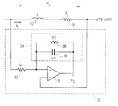
- FIG. 3 shows a measuring circuit according to a first embodiment of the invention
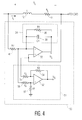
- FIG. 4 shows a measuring circuit according to second embodiment of the invention.
- FIG. 5 illustrates an application of the second embodiment of the invention in a buck converter.
- FIG. 3 shows a current measuring circuit 30 according to a first embodiment of the invention.
- Circuit 30 includes an op-amp 32 , a RC network 34 comprising a resistor 36 and a capacitor 38 , and a resistor 42 .
- RC network 34 is connected in a feedback loop of op-amp 32 .
- Resistor 42 is a scaling resistor used for selecting the appropriate gain of circuit 30 .
- the inductor voltage V L across inductor L and its internal resistor R L are first determined.
- i L V S ⁇ R2/(R1 ⁇ R L ).
- V L /R 2 V S /Z 1
- i L can be obtained with this expression, independent of any frequencies of the AC signals.
- the inductor current i L can be accurately measured with minimum losses since no additional resistor is used in series with the inductor.
- FIG. 4 shows a current measuring circuit 50 according to a second embodiment of the invention.
- This embodiment is suitable for measuring the current of an inductor which has neither terminal grounded.
- a buffer circuit 51 with a unity gain is added to the first embodiment in FIG. 3 .
- Buffer circuit 51 includes an op-amp 52 and four resistors 54 - 57 of the same resistance value R3.
- Buffer circuit 51 provides an output voltage V S ′ with a ground reference, which is equivalent to the output voltage V S of op-amp 32 .
- the ground reference is required in many applications.
- FIG. 5 illustrates an application of current measuring circuit 50 of the second embodiment of the invention in a buck converter 60 .
- a controller 62 controls, via transistors 62 and 64 , the charging and discharging phases of converter 60 , based on the value of the inductor current as measured by measuring circuit 50 .
- the invention may also be used in a converter with a boost topology.
Abstract
Description
Claims (14)
Priority Applications (4)
| Application Number | Priority Date | Filing Date | Title |
|---|---|---|---|
| US09/981,471 US6646450B2 (en) | 2001-10-16 | 2001-10-16 | Method and apparatus for near losslessly measuring inductor current |
| JP2003537186A JP2005506622A (en) | 2001-10-16 | 2002-09-20 | Method and apparatus for measuring inductor current with little loss |
| EP02801438A EP1442511A1 (en) | 2001-10-16 | 2002-09-20 | Method and apparatus for near losslessly measuring inductor current |
| PCT/IB2002/003902 WO2003034577A1 (en) | 2001-10-16 | 2002-09-20 | Method and apparatus for near losslessly measuring inductor current |
Applications Claiming Priority (1)
| Application Number | Priority Date | Filing Date | Title |
|---|---|---|---|
| US09/981,471 US6646450B2 (en) | 2001-10-16 | 2001-10-16 | Method and apparatus for near losslessly measuring inductor current |
Publications (2)
| Publication Number | Publication Date |
|---|---|
| US20030071636A1 US20030071636A1 (en) | 2003-04-17 |
| US6646450B2 true US6646450B2 (en) | 2003-11-11 |
Family
ID=25528397
Family Applications (1)
| Application Number | Title | Priority Date | Filing Date |
|---|---|---|---|
| US09/981,471 Expired - Lifetime US6646450B2 (en) | 2001-10-16 | 2001-10-16 | Method and apparatus for near losslessly measuring inductor current |
Country Status (4)
| Country | Link |
|---|---|
| US (1) | US6646450B2 (en) |
| EP (1) | EP1442511A1 (en) |
| JP (1) | JP2005506622A (en) |
| WO (1) | WO2003034577A1 (en) |
Cited By (10)
| Publication number | Priority date | Publication date | Assignee | Title |
|---|---|---|---|---|
| US20050179423A1 (en) * | 2004-02-18 | 2005-08-18 | Intersil Americas Inc. | Inductor current sensing scheme for PWM regulator |
| US6952093B1 (en) * | 2003-11-07 | 2005-10-04 | National Semiconductor Corporation | Adaptive small-signal compensation for switching regulators |
| US20080031020A1 (en) * | 2006-08-02 | 2008-02-07 | Samsung Electronics Co., Ltd. | Circuit and method for detecting electric current |
| US20110052742A1 (en) * | 2008-11-05 | 2011-03-03 | Mitsubishi Heavy Industries, Ltd. | Mold clamping apparatus |
| US20110213354A1 (en) * | 2010-02-26 | 2011-09-01 | Smith Robert B | Enhanced Lossless Current Sense Circuit |
| US20110260537A1 (en) * | 2006-02-28 | 2011-10-27 | Infineon Technologies Austria Ag | Method of balancing current supplied to a load |
| USRE45634E1 (en) * | 2006-06-23 | 2015-07-28 | Apple Inc. | Multiple-input and multiple-output amplifier using mutual induction in the feedback network |
| US9203300B2 (en) | 2009-05-20 | 2015-12-01 | Alex Mevay | Systems and methods for controlling power converters |
| US20150349634A1 (en) * | 2014-05-27 | 2015-12-03 | Infineon Technologies Austria Ag | Inductor current measurement compensation for switching voltage regulators |
| US20220260628A1 (en) * | 2019-07-26 | 2022-08-18 | Eldor Corporation S.P.A. | Electronic monitoring circuit for detecting the variation in the power or current absorbed by at least one electronic circuit under test and electronic system for testing the operation of the at least one electronic circuit |
Families Citing this family (6)
| Publication number | Priority date | Publication date | Assignee | Title |
|---|---|---|---|---|
| FR2861179B1 (en) * | 2003-10-21 | 2006-01-20 | Thales Sa | DEVICE FOR NON-DISSIPATING CURRENT MEASUREMENT IN INDUCTANCE |
| WO2005078960A1 (en) * | 2004-02-12 | 2005-08-25 | Nec Corporation | Communication system and communication control method |
| CN100429851C (en) * | 2006-08-24 | 2008-10-29 | 上海复旦微电子股份有限公司 | Input detecting circuit for earth-leakage protector with self-diagnosing function |
| GB0919969D0 (en) * | 2009-11-14 | 2009-12-30 | Gigle Semiconductor Ltd | Current measuring apparatus |
| US8847577B2 (en) * | 2010-08-04 | 2014-09-30 | Sensus Spectrum Llc | Method and system of measuring current in an electric meter |
| JP2014506776A (en) * | 2011-02-11 | 2014-03-17 | バランセル(ピーティーワイ)リミテッド | Hysteresis current mode controller for bidirectional converter with lossless inductor current detection |
Citations (4)
| Publication number | Priority date | Publication date | Assignee | Title |
|---|---|---|---|---|
| EP0473428A2 (en) | 1990-08-30 | 1992-03-04 | Sundstrand Corporation | Overcurrent trip circuit |
| US5481178A (en) * | 1993-03-23 | 1996-01-02 | Linear Technology Corporation | Control circuit and method for maintaining high efficiency over broad current ranges in a switching regulator circuit |
| WO1999057578A2 (en) | 1998-05-07 | 1999-11-11 | Airpax Corporation, L.L.C. | Ac current sensor having high accuracy and large bandwidth |
| US6469481B1 (en) * | 1998-12-25 | 2002-10-22 | Kabushiki Kaisha Toyoda Jidoshokki Seisakusho | Parallel RC current detection circuit and DC/DC converter with a parallel RC current detection circuit |
Family Cites Families (2)
| Publication number | Priority date | Publication date | Assignee | Title |
|---|---|---|---|---|
| DE19814681B4 (en) * | 1998-04-01 | 2008-11-13 | Infineon Technologies Ag | Current Mode Switching Regulators |
| US6222745B1 (en) * | 1999-10-19 | 2001-04-24 | Texas Instruments Incorporated | Digitally synthesized multiple phase pulse width modulation |
-
2001
- 2001-10-16 US US09/981,471 patent/US6646450B2/en not_active Expired - Lifetime
-
2002
- 2002-09-20 EP EP02801438A patent/EP1442511A1/en not_active Withdrawn
- 2002-09-20 JP JP2003537186A patent/JP2005506622A/en active Pending
- 2002-09-20 WO PCT/IB2002/003902 patent/WO2003034577A1/en active Application Filing
Patent Citations (5)
| Publication number | Priority date | Publication date | Assignee | Title |
|---|---|---|---|---|
| EP0473428A2 (en) | 1990-08-30 | 1992-03-04 | Sundstrand Corporation | Overcurrent trip circuit |
| US5181155A (en) * | 1990-08-30 | 1993-01-19 | Beg Mirza A | Overcurrent trip circuit |
| US5481178A (en) * | 1993-03-23 | 1996-01-02 | Linear Technology Corporation | Control circuit and method for maintaining high efficiency over broad current ranges in a switching regulator circuit |
| WO1999057578A2 (en) | 1998-05-07 | 1999-11-11 | Airpax Corporation, L.L.C. | Ac current sensor having high accuracy and large bandwidth |
| US6469481B1 (en) * | 1998-12-25 | 2002-10-22 | Kabushiki Kaisha Toyoda Jidoshokki Seisakusho | Parallel RC current detection circuit and DC/DC converter with a parallel RC current detection circuit |
Cited By (16)
| Publication number | Priority date | Publication date | Assignee | Title |
|---|---|---|---|---|
| US9236800B2 (en) | 2001-10-15 | 2016-01-12 | Infineon Technologies Austria Ag | System for balancing current supplied to a load |
| US6952093B1 (en) * | 2003-11-07 | 2005-10-04 | National Semiconductor Corporation | Adaptive small-signal compensation for switching regulators |
| US20050179423A1 (en) * | 2004-02-18 | 2005-08-18 | Intersil Americas Inc. | Inductor current sensing scheme for PWM regulator |
| US7106035B2 (en) * | 2004-02-18 | 2006-09-12 | Intersil Americas Inc. | Inductor current sensing scheme for PWM regulator |
| US8598853B2 (en) * | 2006-02-28 | 2013-12-03 | Infineon Technologies Austria Ag | Method of balancing current supplied to a load |
| US20110260537A1 (en) * | 2006-02-28 | 2011-10-27 | Infineon Technologies Austria Ag | Method of balancing current supplied to a load |
| USRE45634E1 (en) * | 2006-06-23 | 2015-07-28 | Apple Inc. | Multiple-input and multiple-output amplifier using mutual induction in the feedback network |
| US20080031020A1 (en) * | 2006-08-02 | 2008-02-07 | Samsung Electronics Co., Ltd. | Circuit and method for detecting electric current |
| US20110052742A1 (en) * | 2008-11-05 | 2011-03-03 | Mitsubishi Heavy Industries, Ltd. | Mold clamping apparatus |
| US9203300B2 (en) | 2009-05-20 | 2015-12-01 | Alex Mevay | Systems and methods for controlling power converters |
| US20110213354A1 (en) * | 2010-02-26 | 2011-09-01 | Smith Robert B | Enhanced Lossless Current Sense Circuit |
| US8454590B2 (en) * | 2010-02-26 | 2013-06-04 | Covidien Lp | Enhanced lossless current sense circuit |
| US20150349634A1 (en) * | 2014-05-27 | 2015-12-03 | Infineon Technologies Austria Ag | Inductor current measurement compensation for switching voltage regulators |
| US9627969B2 (en) * | 2014-05-27 | 2017-04-18 | Infineon Technologies Austria Ag | Inductor current measurement compensation for switching voltage regulators |
| US20220260628A1 (en) * | 2019-07-26 | 2022-08-18 | Eldor Corporation S.P.A. | Electronic monitoring circuit for detecting the variation in the power or current absorbed by at least one electronic circuit under test and electronic system for testing the operation of the at least one electronic circuit |
| US11860218B2 (en) * | 2019-07-26 | 2024-01-02 | Eldor Corporation S.P.A. | Electronic monitoring circuit for detecting the variation in the power or current absorbed by at least one electronic circuit under test and electronic system for testing the operation of the at least one electronic circuit |
Also Published As
| Publication number | Publication date |
|---|---|
| WO2003034577A1 (en) | 2003-04-24 |
| EP1442511A1 (en) | 2004-08-04 |
| US20030071636A1 (en) | 2003-04-17 |
| JP2005506622A (en) | 2005-03-03 |
Similar Documents
| Publication | Publication Date | Title |
|---|---|---|
| US6646450B2 (en) | Method and apparatus for near losslessly measuring inductor current | |
| US6441597B1 (en) | Method and apparatus for sensing output inductor current in a DC-to-DC power converter | |
| US7233132B1 (en) | Current sensing in multiple coupled inductors by time constant matching to leakage inductance | |
| US8120346B2 (en) | Methods and apparatus for current sensing | |
| US6642696B2 (en) | DC-DC converter with a feedback controller | |
| US7007176B2 (en) | System and method for highly phased power regulation using adaptive compensation control | |
| US7522432B2 (en) | Switching regulator and control circuit and method used therein | |
| US7196499B1 (en) | DC/DC converter with inductor current sensing capability | |
| CN102299627B (en) | DC-DC converters having improved current sensing and related methods | |
| US20060061337A1 (en) | Power factor correction circuit | |
| US4652984A (en) | Self-oscillating power-supply circuit | |
| US6856525B2 (en) | Apparatus and method for controlling voltage regulator and power supply apparatus | |
| WO2007073940A1 (en) | Method for dc/dc conversion and dc/dc converter arrangement | |
| US9960675B2 (en) | Feed-forward control system with current estimator | |
| JP2005506622A5 (en) | ||
| US7352161B2 (en) | Burst-mode switching voltage regulator with ESR compensation | |
| US6809560B1 (en) | Load sensing circuit for a power MOSFET switch | |
| US7952335B2 (en) | Power converter and method for power conversion | |
| US11557917B2 (en) | Switched mode power supplies with configurable communication addresses | |
| JPH10150766A (en) | Switching regulator | |
| JP3580491B2 (en) | Switching power supply | |
| WO2022000199A1 (en) | Multi-phase power supply and electronic device | |
| JPH0974748A (en) | Switching power supply device | |
| JP2003216254A (en) | Semiconductor integrating device | |
| JPH03178555A (en) | Inductance circuit and switching power source using the same |
Legal Events
| Date | Code | Title | Description |
|---|---|---|---|
| AS | Assignment |
Owner name: KONINKLIJKE PHILIPS ELECTRONICS N.V., NETHERLANDS Free format text: ASSIGNMENT OF ASSIGNORS INTEREST;ASSIGNOR:LIEBLER, JEROME E.;REEL/FRAME:012286/0546 Effective date: 20011012 |
|
| STCF | Information on status: patent grant |
Free format text: PATENTED CASE |
|
| AS | Assignment |
Owner name: NXP B.V., NETHERLANDS Free format text: ASSIGNMENT OF ASSIGNORS INTEREST;ASSIGNOR:KONINKLIJKE PHILIPS ELECTRONICS N.V.;REEL/FRAME:018635/0787 Effective date: 20061117 |
|
| FPAY | Fee payment |
Year of fee payment: 4 |
|
| FPAY | Fee payment |
Year of fee payment: 8 |
|
| FPAY | Fee payment |
Year of fee payment: 12 |
|
| AS | Assignment |
Owner name: PHILIPS SEMICONDUCTORS INTERNATIONAL B.V., NETHERL Free format text: ASSIGNMENT OF ASSIGNORS INTEREST;ASSIGNOR:KONINKLIJKE PHILIPS ELECTRONICS N.V.;REEL/FRAME:043951/0127 Effective date: 20060928 Owner name: NXP B.V., NETHERLANDS Free format text: CHANGE OF NAME;ASSIGNOR:PHILIPS SEMICONDUCTORS INTERNATIONAL B.V.;REEL/FRAME:043951/0611 Effective date: 20060929 |