US6622280B1 - Information processing apparatus and method and distribution medium - Google Patents
Information processing apparatus and method and distribution medium Download PDFInfo
- Publication number
- US6622280B1 US6622280B1 US09/257,861 US25786199A US6622280B1 US 6622280 B1 US6622280 B1 US 6622280B1 US 25786199 A US25786199 A US 25786199A US 6622280 B1 US6622280 B1 US 6622280B1
- Authority
- US
- United States
- Prior art keywords
- detecting
- pattern
- mode
- code
- sync
- Prior art date
- Legal status (The legal status is an assumption and is not a legal conclusion. Google has not performed a legal analysis and makes no representation as to the accuracy of the status listed.)
- Expired - Fee Related
Links
Images


Classifications
-
- G—PHYSICS
- G11—INFORMATION STORAGE
- G11B—INFORMATION STORAGE BASED ON RELATIVE MOVEMENT BETWEEN RECORD CARRIER AND TRANSDUCER
- G11B20/00—Signal processing not specific to the method of recording or reproducing; Circuits therefor
- G11B20/10—Digital recording or reproducing
- G11B20/10009—Improvement or modification of read or write signals
- G11B20/10046—Improvement or modification of read or write signals filtering or equalising, e.g. setting the tap weights of an FIR filter
- G11B20/10055—Improvement or modification of read or write signals filtering or equalising, e.g. setting the tap weights of an FIR filter using partial response filtering when writing the signal to the medium or reading it therefrom
-
- G—PHYSICS
- G11—INFORMATION STORAGE
- G11B—INFORMATION STORAGE BASED ON RELATIVE MOVEMENT BETWEEN RECORD CARRIER AND TRANSDUCER
- G11B20/00—Signal processing not specific to the method of recording or reproducing; Circuits therefor
- G11B20/10—Digital recording or reproducing
- G11B20/10009—Improvement or modification of read or write signals
- G11B20/10268—Improvement or modification of read or write signals bit detection or demodulation methods
- G11B20/10287—Improvement or modification of read or write signals bit detection or demodulation methods using probabilistic methods, e.g. maximum likelihood detectors
- G11B20/10296—Improvement or modification of read or write signals bit detection or demodulation methods using probabilistic methods, e.g. maximum likelihood detectors using the Viterbi algorithm
-
- G—PHYSICS
- G11—INFORMATION STORAGE
- G11B—INFORMATION STORAGE BASED ON RELATIVE MOVEMENT BETWEEN RECORD CARRIER AND TRANSDUCER
- G11B20/00—Signal processing not specific to the method of recording or reproducing; Circuits therefor
- G11B20/10—Digital recording or reproducing
- G11B20/14—Digital recording or reproducing using self-clocking codes
- G11B20/1403—Digital recording or reproducing using self-clocking codes characterised by the use of two levels
- G11B20/1423—Code representation depending on subsequent bits, e.g. delay modulation, double density code, Miller code
- G11B20/1426—Code representation depending on subsequent bits, e.g. delay modulation, double density code, Miller code conversion to or from block codes or representations thereof
-
- H—ELECTRICITY
- H03—ELECTRONIC CIRCUITRY
- H03M—CODING; DECODING; CODE CONVERSION IN GENERAL
- H03M13/00—Coding, decoding or code conversion, for error detection or error correction; Coding theory basic assumptions; Coding bounds; Error probability evaluation methods; Channel models; Simulation or testing of codes
- H03M13/33—Synchronisation based on error coding or decoding
-
- H—ELECTRICITY
- H03—ELECTRONIC CIRCUITRY
- H03M—CODING; DECODING; CODE CONVERSION IN GENERAL
- H03M13/00—Coding, decoding or code conversion, for error detection or error correction; Coding theory basic assumptions; Coding bounds; Error probability evaluation methods; Channel models; Simulation or testing of codes
- H03M13/37—Decoding methods or techniques, not specific to the particular type of coding provided for in groups H03M13/03 - H03M13/35
- H03M13/39—Sequence estimation, i.e. using statistical methods for the reconstruction of the original codes
- H03M13/41—Sequence estimation, i.e. using statistical methods for the reconstruction of the original codes using the Viterbi algorithm or Viterbi processors
-
- H—ELECTRICITY
- H03—ELECTRONIC CIRCUITRY
- H03M—CODING; DECODING; CODE CONVERSION IN GENERAL
- H03M13/00—Coding, decoding or code conversion, for error detection or error correction; Coding theory basic assumptions; Coding bounds; Error probability evaluation methods; Channel models; Simulation or testing of codes
- H03M13/63—Joint error correction and other techniques
- H03M13/6331—Error control coding in combination with equalisation
-
- H—ELECTRICITY
- H03—ELECTRONIC CIRCUITRY
- H03M—CODING; DECODING; CODE CONVERSION IN GENERAL
- H03M13/00—Coding, decoding or code conversion, for error detection or error correction; Coding theory basic assumptions; Coding bounds; Error probability evaluation methods; Channel models; Simulation or testing of codes
- H03M13/65—Purpose and implementation aspects
- H03M13/6502—Reduction of hardware complexity or efficient processing
Definitions
- the present invention relates to an information processing apparatus and method and a distribution medium and particularly to an information processing apparatus and method and a distribution medium in which the heading code of the code string to be detected and such code string can surely be detected without increase in the scale of circuit on the occasion of detecting the code string through combination of equalization suitable to the transmission line such as the partial response equalization and the maximum likelihood decoding.
- the PRML Physical Response Maximum Likelihood
- the PRML Partial Response Maximum Likelihood
- the maximum likelihood decoding the Viterbi detection (decoding) is used.
- a data modulation process which is called the MTR (Maximum Transition Run) encoding (hereinafter referred to as the trellis encoding) has been proposed in which encoding is performed before recording of data while the partial response equalization is introduced as it is.
- the code-to-code distance (Euclidean distance) becomes large to realize the detection resistive to noise or distortion.
- the time varying MTR trellis encoding for example, is known, in which the code-to-code distance is increased and the encoding rate has much more improved by executing the MSN (Matched Spectral Null) trellis encoding method to conduct the trellis encoding using the MSN code which can increase the code-to-code distance by giving status to the code to realize matching between Null of power density function of code and Null of frequency characteristic of PRML and also executing the trellis encoding method using the time varying MTR code in which the code is limited depending on the time (channel clock).
- MSN Matched Spectral Null
- the detecting circuit for detecting (decoding) the code string encoded by the encoding process having time limitation such as the MSN trellis encoding and time varying MTR trellis encoding method such as the MSN trellis encoding and time varying MTR trellis encoding cannot result in the correct detection result if the code string to be detected is not detected from the heading code. Therefore, a pattern (hereinafter referred to as sync-byte pattern) is added to indicate the heading code of the code string and thereby, the detecting circuit (trellis Viterbi detecting circuit) starts the detecting operation (decoding operation) of the code string by detecting this sync-byte pattern.
- this sync-byte pattern is not given the time limitation, status and path structure are different for detection of the synch-byte pattern from those of the case where the code string having the time limitation such as the time varying MTR code string is detected. Therefore, a detecting circuit for the sync-byte pattern has to be prepared in addition to the trellis Viterbi detecting circuit, generating a problem that the circuit field increases.
- the present invention has been proposed considering such background explained above and therefore the present invention is intended to always and surely detect the sync-byte pattern.
- an information processing apparatus of the present invention is characterized in comprising a detecting means for detecting a code string encoded depending on a rule including a time limitation, an adding means for adding the pattern indicating a heading code of the code string to the stage preceding the code string and a switching means for switching the modes between a first mode for executing the detecting operation by the detecting means without relation to the rule including the time limitation and a second mode for executing the detecting operation by the detecting means depending on the rule including the time limitation, whereby the switching means switches the mode of the detecting means to the first mode in order to detect, with the detecting means, the pattern added by the adding means and also to the second mode in order to detect, by the detecting means, the code string.
- an information processing method of the present invention is characterized in comprising a detecting step for detecting a code string decoded depending on a rule including a time limitation, an adding step for adding the pattern indicating a heading code of the code string to the stage preceding the code string and a switching step for switching a operation mode between a first mode to conduct the detecting operation without relation to the rule including the time limitation in the detecting step, and a second mode to conduct the detecting operation depending on the rule including the time limitation in the detecting step, whereby, in the switching step, when the pattern added in the adding step is detected in the detecting step, the detection step mode is switched to the first mode and when the code string is detected in the detecting step, the detecting step mode is switched to the second mode.
- a distribution medium of the present invention is characterized in having recorded thereupon a computer-readable program including a detecting step for detecting a code string decoded depending on a rule including a time limitation, an adding step for adding the pattern indicating a heading code of the code string to the stage preceding the code string and a switching step for switching a mode of operation between a first mode to conduct the detecting operation without relation to the rule including the time limitation in the detecting step, and a second mode to conduct the detecting operation depending on the rule including the time limitation in the detecting step, whereby, in the switching step, when the pattern added in the adding step is detected in the detecting step, the detection step mode is switched to the first mode and when the code string is detected in the detecting step, the detecting step mode is switched to the second mode.
- the operation mode when the pattern indicating the heading code of the code string is detected, the operation mode is switched to the first mode to conduct the detecting operation without relation to the time limitation and when the code string is detected, the operation mode is switched to the second mode to conduct the detecting operation depending on the time limitation.
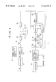
- FIG. 1 is a block diagram showing an example of structure of a preferred embodiment of a digital magnetic disk recording/reproducing apparatus to which the information processing apparatus of the present invention is applied.
- FIG. 2 is a diagram for explaining data sequence in unit of sector.
- FIG. 3 is a block diagram showing an example of structure of the maximum likelihood decoding circuit of FIG. 1 .
- FIG. 4 is a diagram for explaining the sync-byte pattern.
- FIG. 5 is a diagram showing an example of a trellis diagram used in the Viterbi detecting circuit.
- FIG. 6 is a diagram for explaining an error pattern.
- FIG. 7 is a diagram for showing the other example of the trellis diagram of FIG. 5 .
- FIG. 8 is a diagram for explaining the simulation result.
- the information processing apparatus is characterized in comprising a detecting means (for example, Viterbi detecting circuit 44 of FIG. 3) for detecting the code string encoded depending on the rule including the time limitation, an adding means (for example, format data generating circuit 14 ) for adding the pattern indicating the heading code of the code string to the preceding stage of the code string and a switching means (for example, sync-byte detecting circuit 46 of FIG.
- a detecting means for example, Viterbi detecting circuit 44 of FIG. 3
- an adding means for example, format data generating circuit 14
- a switching means for example, sync-byte detecting circuit 46 of FIG.
- the switching means switches the operation mode of the detecting means to the first mode when the detecting means detects the pattern added by the adding means and to the second mode when the detecting means detects the code string.
- FIG. 1 shows an example of structure of a digital magnetic disk recording/reproducing apparatus to which the information processing apparatus of the present invention is applied.
- E2PR4 Extended Partial Response Class 4
- the user data string (for example, data string of 16 bits) to be recorded as the input to the terminal 11 is supplied to an encoder 12 .
- the encoder 12 executes the time varying MTR trellis encoding process for the user data supplied from the terminal 11 and then outputs the user data string encoded to the time varying MTR code string of 18 bits to the NRZ circuit 13 .
- the NRZ circuit 13 executes the NRZ (Non Return to Zero) process for the user data string supplied from the encoder 12 .
- the format data generating circuit 14 generates the VFO pattern (VFO Sync pattern) for frequency and phase matching of the VFO (Variable Frequency Oscillator) comprised in the PLL circuit 23 , sync-byte pattern indicating the heading code (detection starting position to start detection of user data by the Viterbi detecting circuit 44 ) of the user data string and application equalizing training pattern (Adaptive EQ Training pattern) for training of the equalizing characteristic in the E2PR4 equalizer and also changes over the switch 15 to provide the data sequence in which the user data string output from the NRZ circuit 18 after the VFO pattern, sync-byte pattern and application equalizing training pattern becomes continuous.
- VFO Sync pattern VFO Sync pattern
- sync-byte pattern indicating the heading code (detection starting position to start detection of user data by the Viterbi detecting circuit 44 ) of the user data string
- application equalizing training pattern Adaptive EQ Training pattern
- An amplifier 16 amplifies the data string (VFO pattern, sync-byte pattern, application equalizing training pattern and user data string) output from the switch 15 to record the data string to a recording medium 17 (for example, magneto-optical disk) using a recording head 18 .
- a reproduction head 19 reproduces data string from the recording medium 17 and then outputs this data string to an amplifier 20 .
- the amplifier 20 amplifies the data string reproduced by the reproduction head 19 and then outputs the data to an E2PR4 equalizer 21 .
- the characteristic of the E2PR4 equalizer can be expressed by the following interference polynomial.
- the E2PR4 equalizer 21 is mainly structured by the PR4 equalizer 22 and digital filters 32 - 1 , 32 - 2 of two stages.
- This E2PR4 equalizer 21 can also be formed in the application equalization type.
- the PR4 equalizer 22 executes the partial response equalization (PR4 equalization) using the E2PR4 to the data string supplied from the amplifier 20 and then outputs the equalized waveform to the PLL circuit 23 and a sampler (sampling circuit) 24 .
- the PLL circuit 23 extracts the channel clock CK from the output waveform (equalized waveform) of the PR4 equalizer and then outputs this channel clock CK to the sampler 24 , maximum likelihood decoding circuit 29 and decoder 30 .
- These sampler 24 , maximum likelihood decoding circuit 29 and decoder 30 are designed to operate conforming to the channel clock CK supplied from the PLL circuit 23 .
- the sampler 24 (sampling circuit) samples the equalized waveform supplied from the PR4 equalizer 22 conforming to the channel clock CK supplied from the PLL circuit 23 .
- the digital filters 32 - 1 , 32 - 2 are cascade-connected.
- the digital filter 32 - 1 is structured by a unit delay element (D) 25 and an adding circuit 26 enough to the channel clock CK, while the digital filter 32 - 2 is structured by a unit delay element 27 and an adding circuit 28 .
- the maximum likelihood decoding circuit 9 detects the sync-byte pattern (heading code of the user data string) for the output from the E2PR4 equalizer 21 and thereafter executes the maximum likelihood decoding process of the user data string and then outputs the user data string decoded by the maximum likelihood decoding method to the decoder 30 .
- the decoder 30 is set in the conjugate relation with the encoder 16 and decodes the code string output from the maximum likelihood decoding circuit 29 and outputs the decoded code string via the output terminal 31 .
- FIG. 3 shows an example of detail structure of the maximum likelihood decoding circuit 29 .
- the data string from the E2PR4 equalizer 21 is supplied to a delay circuit 42 and a switch 43 via the terminal 41 .
- the delay circuit 42 delays the input data string as much as the length (for example, 32 bits) of a path memory 45 comprised in the Viterbi detecting circuit 44 and then outputs the data string to the switch 43 .
- the switch 43 switches the data strings supplied from the terminal 41 and the delay circuit 42 and then outputs the switched data string to the Viterbi detecting circuit 44 depending on the signal supplied from the sync-byte detecting circuit 46 .
- the Viterbi detecting circuit 44 executes the Viterbi detection for the input data string.
- the path memory 45 is capable of storing a temporary judging value until the detection result of the Viterbi detecting circuit 44 is defined and also outputs the defined detecting result to the sync-byte detecting circuit 46 or switch 47 .
- the sync-byte detecting circuit 46 detects the sync-byte from the detection result supplied from the path memory 45 and outputs the detection signal to the switch 43 , switch 47 and Viterbi detecting circuit 44 in the timing to start detection of the user data string.
- the switch 43 is switched to select an output from the delay circuit 42 in the timing that the detected signal is supplied from the sync-byte detecting circuit 46 , while the switch 47 is switched to output the data (detection result) from the path memory 45 to the terminal 48 in the timing that the detected signal is supplied from the sync-byte detecting circuit 46 .
- the Viterbi detecting circuit 44 initializes (resets) the path memory 45 and path metric corresponding to the detected signal from the sync-byte detecting circuit 46 and subsequently starts the trellis Viterbi detection with a time limitation of the trellis path for the data supplied from the switch 43 .
- the Viterbi detecting circuit 44 executes first the detecting operation in such a mode that the time limitation is not given to the trellis path, while the sync-byte detecting circuit 46 detects, in this timing, the sync-byte pattern from the detection result of the Viterbi detecting circuit 44 .
- the sync-byte detecting circuit 46 Upon detection of the sync-byte pattern, the sync-byte detecting circuit 46 outputs the detected signal to the switch 43 , switch 47 and Viterbi detecting circuit 44 in such a timing that the user data string should be input to the Viterbi detecting circuit 44 (the timing that the user data string should be detected).
- the Viterbi detecting circuit 44 initializes, corresponding to this process, the path memory 45 and path metric and subsequently starts trellis Viterbi detection in the mode accompanied by the time limitation on the trellis path. Thereby, both sync-byte pattern not given the time limitation and the user data string (time varying MTR code string) having the time limitation can be detected by the Viterbi detecting circuit 44 .
- the VFO pattern, sync-byte pattern and application equalizing training pattern shown in FIG. 2 are formed as the code not including the code for three continuous transitions and the Hamming distance between the VFO pattern and sync-byte pattern is set, for example, to four (4).
- the VFO pattern is defined as the pattern expressed by ⁇ . . . 001100110011 . . . ⁇ with the NRZ notation
- the sync-byte pattern is defined as the pattern expressed by ⁇ 10001000001000001000 ⁇ with the NRZ notation, namely as the pattern of 20 bits in which the bit unit becomes 4T, 6T, 6T, 4T considering the continuity with the VFO pattern as shown FIG. 4 .
- the application equalizing training pattern is defined as the pattern of 36 bits in which the bits are sequentially arranged as 2T, 7T, 4T, 5T, 8T, 1T, 3T, 6T expressed by ⁇ 10100000010001000010000000100100000 ⁇ with the NRZI notation.
- the VFO pattern, sync-byte pattern and application equalizing training pattern are defined not to include the code of three continuous transitions. Namely, these patterns satisfy the conditions of the MTR code. Therefore, the Viterbi detecting circuit 44 detects, as shown in FIG. 5, respective patterns and user data string depending on the trellis structure (only a part is indicated in the figure) for MTR code detection. Thereby, the minimum code-to-code distance (Euclidean distance) can be set to ⁇ square root over ( ) ⁇ 10 for detection of each pattern.
- an error bit (indicated as the hatched area in the figure) in which the code-to-code distance is isolated as much as ⁇ square root over ( ) ⁇ 10) can be set to 1 bit in the respective condition (respective condition corresponds to the condition of the trellis structure shown in FIG. 5 ). Therefore, probability of erroneous detection can be lowered.
- the Viterbi detecting circuit 44 is structured to correct errors up to two errors because the Hamming distance of the VCO pattern and sync-byte pattern is four (4). It is because when the second minimum code-to-code distance is ⁇ square root over ( ) ⁇ 12, correction is possible since simultaneous generation of two bits may be considered.
- the sync-byte detecting circuit 46 compares, as explained above, the bit string detected by the Viterbi detecting circuit 44 with the sync-byte and detects the error within two bits as the sync-byte.
- the Viterbi detecting circuit 44 detects the time varying MTR code as the user data string depending on the trellis structure shown in FIG. 5, the correct detection result cannot be obtained in a certain case because the path covering all time varying MTR codes is not prepared. Therefore, the application equalizing training pattern is defined in the bit length longer than that which can be stored by the path memory 45 .
- the bit length of the path memory 45 is set to 32 bits and the application equalizing training pattern is set to 36 bits. Therefore, an allowance up to the input of user data string to the Viterbi detecting circuit 44 is generated and thereby the sync-byte pattern detection probability is not lowered.
- the Viterbi detecting circuit 44 may be capable of conducting the Viterbi detection using the trellis structure shown in FIG. 7 .
- transition between the condition S 5 and condition S 10 is inhibited.
- the Viterbi detecting circuit 44 using this trellis structure can detect all data sequences including the user data. In this case, it is verified that the minimum code-to-code distance can be assured for only ⁇ square root over ( ) ⁇ 6 for the data sequence other than the sync-byte pattern, but there is no error of code-to-code distance under 6 shown in FIG. 6 for the sync-byte pattern. Namely, detection can be realized in the minimum code-to-code distance of ⁇ square root over ( ) ⁇ 10 or more for the sync-byte pattern.
- FIG. 8 shows simulation result of generation probability of sync-byte erroneous detection error and sync-byte detection error.
- the horizontal axis is plotting S/N ratio (Signal to Noise Ratio) and the vertical axis is plotting probability of each error.
- a curve A shows a bit error rate for detection of the time varying MTR code (user data) in the code-to-code distance of ⁇ square root over ( ) ⁇ 10.
- the sync-byte detection error is generated when detection is conducted at the correct position (the natural sync-byte position) and is indicated by the curve B (when detection is conducted using the trellis structure shown in FIG. 7) and the curve D (when detection is conducted using the trellis structure shown in FIG. 5 ).
- the sync-byte erroneous detection error is generated when sync-byte is detected at the erroneous position (position preceding the natural sync-byte position) and is shown by the curve C (when detection is conducted using the trellis structure shown in FIG. 7) and by the curve E (when detection is conducted using the trellis structure shown in FIG. 5 ).
- probability (in the case of the curve B) of the sync-byte erroneous detection error obtained is in the order of 10 ⁇ circumflex over ( ) ⁇ ( ⁇ 7), for example, when the bit error rate (curve A) during detection of the time varying MTR code is about 10 ⁇ circumflex over ( ) ⁇ ( ⁇ 5).
- the sync-byte detection error (curve D) is set up lower than that of the sync-byte detection error (curve B).
- the E2PR4 equalizer is considered as the object, but the present invention can also be applied to the partial response of the E3PR4 or the equalizer of higher class.
- the present invention is applied to the digital magnetic disk recording/reproducing apparatus, but it can also be applied to the other information recording/reproducing apparatus and information transmitting apparatus.
- a communication medium such as the network and satellite can also be used in addition to the recording medium such as magnetic disk, CD-ROM and solid state memory device.
- both the code string having time limitation and the sync-byte pattern indicating the heading code of the code string can surely be detected without increase of the circuit scale.
Abstract
It is an object to save a circuit scale and simultaneously improve sync-byte pattern detecting performance. A Viterbi detecting circuit executes first the detecting operation without relation to time limitation. A sync-byte detecting circuit detects the sync-byte from the detection result supplied from a path memory built in the Viterbi detecting circuit and also outputs the detected signal to switches and Viterbi detecting circuit in the timing to start detection of user data. The Viterbi circuit initializes (resets) the path memory and path metric corresponding to the detected signal supplied from the sync-byte detecting circuit and also starts subsequently the trellis Viterbi detection accompanied by the time limitation of the trellis path to the data supplied from the switch.
Description
The present application claims priority to Japanese Application No. P10 051771 filed Mar. 4, 1998 which application is incorporated herein by reference to the extent permitted by law.
1. Field of the Invention
The present invention relates to an information processing apparatus and method and a distribution medium and particularly to an information processing apparatus and method and a distribution medium in which the heading code of the code string to be detected and such code string can surely be detected without increase in the scale of circuit on the occasion of detecting the code string through combination of equalization suitable to the transmission line such as the partial response equalization and the maximum likelihood decoding.
2. Description of the Prior Art
It is required for a digital communication apparatus and a digital recording/reproducing apparatus to transmit or record data in the density as higher as possible. For this purpose, the PRML (Partial Response Maximum Likelihood) system for detecting(decoding) data string (code string) by combination of the equalization suitable to the transmission path such as partial response equalization (for example, the equalization of sampling waveform for convolution of code) and the maximum likelihood decoding (detection) is well known. As the maximum likelihood decoding, the Viterbi detection (decoding) is used.
In such PRML system, as a method for realizing detection resistive to noise or distortion, a data modulation process which is called the MTR (Maximum Transition Run) encoding (hereinafter referred to as the trellis encoding) has been proposed in which encoding is performed before recording of data while the partial response equalization is introduced as it is. According to this system, the code-to-code distance (Euclidean distance) becomes large to realize the detection resistive to noise or distortion.
Moreover, the time varying MTR trellis encoding, for example, is known, in which the code-to-code distance is increased and the encoding rate has much more improved by executing the MSN (Matched Spectral Null) trellis encoding method to conduct the trellis encoding using the MSN code which can increase the code-to-code distance by giving status to the code to realize matching between Null of power density function of code and Null of frequency characteristic of PRML and also executing the trellis encoding method using the time varying MTR code in which the code is limited depending on the time (channel clock).
Here, the detecting circuit (trellis Viterbi detecting circuit) for detecting (decoding) the code string encoded by the encoding process having time limitation such as the MSN trellis encoding and time varying MTR trellis encoding method such as the MSN trellis encoding and time varying MTR trellis encoding cannot result in the correct detection result if the code string to be detected is not detected from the heading code. Therefore, a pattern (hereinafter referred to as sync-byte pattern) is added to indicate the heading code of the code string and thereby, the detecting circuit (trellis Viterbi detecting circuit) starts the detecting operation (decoding operation) of the code string by detecting this sync-byte pattern.
However, since this sync-byte pattern is not given the time limitation, status and path structure are different for detection of the synch-byte pattern from those of the case where the code string having the time limitation such as the time varying MTR code string is detected. Therefore, a detecting circuit for the sync-byte pattern has to be prepared in addition to the trellis Viterbi detecting circuit, generating a problem that the circuit field increases.
The present invention has been proposed considering such background explained above and therefore the present invention is intended to always and surely detect the sync-byte pattern.
According to one aspect of the present invention, an information processing apparatus of the present invention is characterized in comprising a detecting means for detecting a code string encoded depending on a rule including a time limitation, an adding means for adding the pattern indicating a heading code of the code string to the stage preceding the code string and a switching means for switching the modes between a first mode for executing the detecting operation by the detecting means without relation to the rule including the time limitation and a second mode for executing the detecting operation by the detecting means depending on the rule including the time limitation, whereby the switching means switches the mode of the detecting means to the first mode in order to detect, with the detecting means, the pattern added by the adding means and also to the second mode in order to detect, by the detecting means, the code string.
According to another aspect of the present invention, an information processing method of the present invention is characterized in comprising a detecting step for detecting a code string decoded depending on a rule including a time limitation, an adding step for adding the pattern indicating a heading code of the code string to the stage preceding the code string and a switching step for switching a operation mode between a first mode to conduct the detecting operation without relation to the rule including the time limitation in the detecting step, and a second mode to conduct the detecting operation depending on the rule including the time limitation in the detecting step, whereby, in the switching step, when the pattern added in the adding step is detected in the detecting step, the detection step mode is switched to the first mode and when the code string is detected in the detecting step, the detecting step mode is switched to the second mode.
According to the other aspect of the present invention, a distribution medium of the present invention is characterized in having recorded thereupon a computer-readable program including a detecting step for detecting a code string decoded depending on a rule including a time limitation, an adding step for adding the pattern indicating a heading code of the code string to the stage preceding the code string and a switching step for switching a mode of operation between a first mode to conduct the detecting operation without relation to the rule including the time limitation in the detecting step, and a second mode to conduct the detecting operation depending on the rule including the time limitation in the detecting step, whereby, in the switching step, when the pattern added in the adding step is detected in the detecting step, the detection step mode is switched to the first mode and when the code string is detected in the detecting step, the detecting step mode is switched to the second mode.
According to the aspects of the present invention, in the information processing apparatus, information processing method and distribution medium of the present invention, when the pattern indicating the heading code of the code string is detected, the operation mode is switched to the first mode to conduct the detecting operation without relation to the time limitation and when the code string is detected, the operation mode is switched to the second mode to conduct the detecting operation depending on the time limitation.
FIG. 1 is a block diagram showing an example of structure of a preferred embodiment of a digital magnetic disk recording/reproducing apparatus to which the information processing apparatus of the present invention is applied.
FIG. 2 is a diagram for explaining data sequence in unit of sector.
FIG. 3 is a block diagram showing an example of structure of the maximum likelihood decoding circuit of FIG. 1.
FIG. 4 is a diagram for explaining the sync-byte pattern.
FIG. 5 is a diagram showing an example of a trellis diagram used in the Viterbi detecting circuit.
FIG. 6 is a diagram for explaining an error pattern.
FIG. 7 is a diagram for showing the other example of the trellis diagram of FIG. 5.
FIG. 8 is a diagram for explaining the simulation result.
The preferred embodiments of the present invention will be explained below but characteristics of the present invention will be described by adding the corresponding embodiments (however, only an example) within the parentheses given after each means in view of making clear the correspondence between each means of the present invention and the embodiments. This description, however, does not mean to be limited to the description of each means.
The information processing apparatus according to one aspect is characterized in comprising a detecting means (for example, Viterbi detecting circuit 44 of FIG. 3) for detecting the code string encoded depending on the rule including the time limitation, an adding means (for example, format data generating circuit 14) for adding the pattern indicating the heading code of the code string to the preceding stage of the code string and a switching means (for example, sync-byte detecting circuit 46 of FIG. 3) for switching the operation mode between the first mode for conducting detecting operation without relation to the time limitation and the second mode for conducting detecting operation depending on the time limitation, whereby the switching means switches the operation mode of the detecting means to the first mode when the detecting means detects the pattern added by the adding means and to the second mode when the detecting means detects the code string.
FIG. 1 shows an example of structure of a digital magnetic disk recording/reproducing apparatus to which the information processing apparatus of the present invention is applied. In this digital magnetic disk recording/reproducing apparatus 1, E2PR4 (Extended Extended Partial Response Class 4) should be applied as the partial response. The user data string (for example, data string of 16 bits) to be recorded as the input to the terminal 11 is supplied to an encoder 12. The encoder 12 executes the time varying MTR trellis encoding process for the user data supplied from the terminal 11 and then outputs the user data string encoded to the time varying MTR code string of 18 bits to the NRZ circuit 13. The NRZ circuit 13 executes the NRZ (Non Return to Zero) process for the user data string supplied from the encoder 12.
The format data generating circuit 14 generates the VFO pattern (VFO Sync pattern) for frequency and phase matching of the VFO (Variable Frequency Oscillator) comprised in the PLL circuit 23, sync-byte pattern indicating the heading code (detection starting position to start detection of user data by the Viterbi detecting circuit 44) of the user data string and application equalizing training pattern (Adaptive EQ Training pattern) for training of the equalizing characteristic in the E2PR4 equalizer and also changes over the switch 15 to provide the data sequence in which the user data string output from the NRZ circuit 18 after the VFO pattern, sync-byte pattern and application equalizing training pattern becomes continuous. An amplifier 16 amplifies the data string (VFO pattern, sync-byte pattern, application equalizing training pattern and user data string) output from the switch 15 to record the data string to a recording medium 17 (for example, magneto-optical disk) using a recording head 18.
A reproduction head 19 reproduces data string from the recording medium 17 and then outputs this data string to an amplifier 20. The amplifier 20 amplifies the data string reproduced by the reproduction head 19 and then outputs the data to an E2PR4 equalizer 21.
Here, when a unit delay time of the channel clock CK is defined as D, the characteristic of the E2PR4 equalizer can be expressed by the following interference polynomial.
Here, indicates the power. The formula (1) can also be expressed by the following formula (2).
Namely, it can be understood that the E2PR4 equalizer 21 is mainly structured by the PR4 equalizer 22 and digital filters 32-1, 32-2 of two stages. This E2PR4 equalizer 21 can also be formed in the application equalization type.
In the E2PR4 equalizer 21, the PR4 equalizer 22 executes the partial response equalization (PR4 equalization) using the E2PR4 to the data string supplied from the amplifier 20 and then outputs the equalized waveform to the PLL circuit 23 and a sampler (sampling circuit) 24. The PLL circuit 23 extracts the channel clock CK from the output waveform (equalized waveform) of the PR4 equalizer and then outputs this channel clock CK to the sampler 24, maximum likelihood decoding circuit 29 and decoder 30. These sampler 24, maximum likelihood decoding circuit 29 and decoder 30 are designed to operate conforming to the channel clock CK supplied from the PLL circuit 23. The sampler 24 (sampling circuit) samples the equalized waveform supplied from the PR4 equalizer 22 conforming to the channel clock CK supplied from the PLL circuit 23.
In the stage after the sampler 24, the digital filters 32-1, 32-2 are cascade-connected. The digital filter 32-1 is structured by a unit delay element (D) 25 and an adding circuit 26 enough to the channel clock CK, while the digital filter 32-2 is structured by a unit delay element 27 and an adding circuit 28.
The maximum likelihood decoding circuit 9 detects the sync-byte pattern (heading code of the user data string) for the output from the E2PR4 equalizer 21 and thereafter executes the maximum likelihood decoding process of the user data string and then outputs the user data string decoded by the maximum likelihood decoding method to the decoder 30. The decoder 30 is set in the conjugate relation with the encoder 16 and decodes the code string output from the maximum likelihood decoding circuit 29 and outputs the decoded code string via the output terminal 31.
FIG. 3 shows an example of detail structure of the maximum likelihood decoding circuit 29. In this example, the data string from the E2PR4 equalizer 21 is supplied to a delay circuit 42 and a switch 43 via the terminal 41. The delay circuit 42 delays the input data string as much as the length (for example, 32 bits) of a path memory 45 comprised in the Viterbi detecting circuit 44 and then outputs the data string to the switch 43. The switch 43 switches the data strings supplied from the terminal 41 and the delay circuit 42 and then outputs the switched data string to the Viterbi detecting circuit 44 depending on the signal supplied from the sync-byte detecting circuit 46. The Viterbi detecting circuit 44 executes the Viterbi detection for the input data string. The path memory 45 is capable of storing a temporary judging value until the detection result of the Viterbi detecting circuit 44 is defined and also outputs the defined detecting result to the sync-byte detecting circuit 46 or switch 47.
The sync-byte detecting circuit 46 detects the sync-byte from the detection result supplied from the path memory 45 and outputs the detection signal to the switch 43, switch 47 and Viterbi detecting circuit 44 in the timing to start detection of the user data string. The switch 43 is switched to select an output from the delay circuit 42 in the timing that the detected signal is supplied from the sync-byte detecting circuit 46, while the switch 47 is switched to output the data (detection result) from the path memory 45 to the terminal 48 in the timing that the detected signal is supplied from the sync-byte detecting circuit 46. Moreover, the Viterbi detecting circuit 44 initializes (resets) the path memory 45 and path metric corresponding to the detected signal from the sync-byte detecting circuit 46 and subsequently starts the trellis Viterbi detection with a time limitation of the trellis path for the data supplied from the switch 43.
Namely, the Viterbi detecting circuit 44 executes first the detecting operation in such a mode that the time limitation is not given to the trellis path, while the sync-byte detecting circuit 46 detects, in this timing, the sync-byte pattern from the detection result of the Viterbi detecting circuit 44. Upon detection of the sync-byte pattern, the sync-byte detecting circuit 46 outputs the detected signal to the switch 43, switch 47 and Viterbi detecting circuit 44 in such a timing that the user data string should be input to the Viterbi detecting circuit 44 (the timing that the user data string should be detected). The Viterbi detecting circuit 44 initializes, corresponding to this process, the path memory 45 and path metric and subsequently starts trellis Viterbi detection in the mode accompanied by the time limitation on the trellis path. Thereby, both sync-byte pattern not given the time limitation and the user data string (time varying MTR code string) having the time limitation can be detected by the Viterbi detecting circuit 44.
Here, the VFO pattern, sync-byte pattern and application equalizing training pattern shown in FIG. 2 are formed as the code not including the code for three continuous transitions and the Hamming distance between the VFO pattern and sync-byte pattern is set, for example, to four (4). The VFO pattern is defined as the pattern expressed by { . . . 001100110011 . . . } with the NRZ notation, while the sync-byte pattern is defined as the pattern expressed by {10001000001000001000} with the NRZ notation, namely as the pattern of 20 bits in which the bit unit becomes 4T, 6T, 6T, 4T considering the continuity with the VFO pattern as shown FIG. 4. Moreover, the application equalizing training pattern is defined as the pattern of 36 bits in which the bits are sequentially arranged as 2T, 7T, 4T, 5T, 8T, 1T, 3T, 6T expressed by {10100000010001000010000000100100000} with the NRZI notation.
Moreover, the VFO pattern, sync-byte pattern and application equalizing training pattern are defined not to include the code of three continuous transitions. Namely, these patterns satisfy the conditions of the MTR code. Therefore, the Viterbi detecting circuit 44 detects, as shown in FIG. 5, respective patterns and user data string depending on the trellis structure (only a part is indicated in the figure) for MTR code detection. Thereby, the minimum code-to-code distance (Euclidean distance) can be set to {square root over ( )}10 for detection of each pattern.
Since the sync-byte pattern is set as the pattern explained above, an error bit (indicated as the hatched area in the figure) in which the code-to-code distance is isolated as much as {square root over ( )}10) can be set to 1 bit in the respective condition (respective condition corresponds to the condition of the trellis structure shown in FIG. 5). Therefore, probability of erroneous detection can be lowered.
The Viterbi detecting circuit 44 is structured to correct errors up to two errors because the Hamming distance of the VCO pattern and sync-byte pattern is four (4). It is because when the second minimum code-to-code distance is {square root over ( )}12, correction is possible since simultaneous generation of two bits may be considered.
The sync-byte detecting circuit 46 compares, as explained above, the bit string detected by the Viterbi detecting circuit 44 with the sync-byte and detects the error within two bits as the sync-byte.
By the way, when the Viterbi detecting circuit 44 detects the time varying MTR code as the user data string depending on the trellis structure shown in FIG. 5, the correct detection result cannot be obtained in a certain case because the path covering all time varying MTR codes is not prepared. Therefore, the application equalizing training pattern is defined in the bit length longer than that which can be stored by the path memory 45. In the preferred embodiment of the present invention, the bit length of the path memory 45 is set to 32 bits and the application equalizing training pattern is set to 36 bits. Therefore, an allowance up to the input of user data string to the Viterbi detecting circuit 44 is generated and thereby the sync-byte pattern detection probability is not lowered.
Here, the Viterbi detecting circuit 44 may be capable of conducting the Viterbi detection using the trellis structure shown in FIG. 7. In the trellis structure of FIG. 7, transition between the condition S5 and condition S10 is inhibited. The Viterbi detecting circuit 44 using this trellis structure can detect all data sequences including the user data. In this case, it is verified that the minimum code-to-code distance can be assured for only {square root over ( )}6 for the data sequence other than the sync-byte pattern, but there is no error of code-to-code distance under 6 shown in FIG. 6 for the sync-byte pattern. Namely, detection can be realized in the minimum code-to-code distance of {square root over ( )}10 or more for the sync-byte pattern.
FIG. 8 shows simulation result of generation probability of sync-byte erroneous detection error and sync-byte detection error. In this figure, the horizontal axis is plotting S/N ratio (Signal to Noise Ratio) and the vertical axis is plotting probability of each error. A curve A shows a bit error rate for detection of the time varying MTR code (user data) in the code-to-code distance of {square root over ( )}10. The sync-byte detection error is generated when detection is conducted at the correct position (the natural sync-byte position) and is indicated by the curve B (when detection is conducted using the trellis structure shown in FIG. 7) and the curve D (when detection is conducted using the trellis structure shown in FIG. 5). Moreover, the sync-byte erroneous detection error is generated when sync-byte is detected at the erroneous position (position preceding the natural sync-byte position) and is shown by the curve C (when detection is conducted using the trellis structure shown in FIG. 7) and by the curve E (when detection is conducted using the trellis structure shown in FIG. 5).
As shown in this figure, probability (in the case of the curve B) of the sync-byte erroneous detection error obtained is in the order of 10{circumflex over ( )}(−7), for example, when the bit error rate (curve A) during detection of the time varying MTR code is about 10{circumflex over ( )}(−5). Moreover, it can also be understood that the sync-byte detection error (curve D) is set up lower than that of the sync-byte detection error (curve B).
In above description, the E2PR4 equalizer is considered as the object, but the present invention can also be applied to the partial response of the E3PR4 or the equalizer of higher class. In addition, the present invention is applied to the digital magnetic disk recording/reproducing apparatus, but it can also be applied to the other information recording/reproducing apparatus and information transmitting apparatus.
As a distribution medium for distributing to users the computer programs to execute the various processes explained above, a communication medium such as the network and satellite can also be used in addition to the recording medium such as magnetic disk, CD-ROM and solid state memory device.
As explained above, according to the information processing apparatus, information processing method and distribution medium of the present invention, since the operation mode is switched to the first mode to perform the detecting operation without relation to the time limitation when the pattern indicating the heading code of the code string is detected and to the second mode to perform the detecting operation depending on the time limitation when the code string is detected, both the code string having time limitation and the sync-byte pattern indicating the heading code of the code string can surely be detected without increase of the circuit scale.
Claims (3)
1. An information processing apparatus comprising:
detecting means for detecting a code string encoded depending on a rule including a time limitation;
adding means for adding a pattern indicating a heading code of said code string to the stage preceding said code string; and
switching means for switching the operation mode of said detecting means between a first mode to perform the detecting operation without relation to said rule including said time limitation and a second mode to perform the detecting operation depending on said rule including said time limitation, whereby
said switching means switches the mode of said detecting means to said first mode when said pattern added by said adding means is detected by said detecting means and to said second mode when said code string is detected by said detecting means, whereby
said pattern added by said adding means provides a Hamming distance of 4 or more between said pattern and a second pattern located at the stage preceding said pattern, and whereby
said detecting means corrects, at the time of detecting said pattern, an error of a number of bits corresponding to said Hamming distance.
2. An information processing method comprising:
a detecting step for detecting a code string encoded depending on a rule including a time limitation;
an adding step for adding a pattern indicating a heading code of said code string to the stage preceding said code string, said pattern added by said adding step providing a Hamming distance of 4 or more between said pattern and a second pattern located at the stage preceding said pattern; and
a switching step for switching a mode between a first mode to perform the detecting operation without relation to said rule including said time limitation in said detecting step, and a second mode to perform the detecting operation depending on said rule including said time limitation in said detecting step; whereby
in said switching step, the mode of said detecting step is switched to said first mode when said pattern added in said adding step is detected in said detecting step, and the mode of said detecting step is switched to the second mode when said code string is detected in said detecting step,
and whereby said detecting step corrects, at the time of detecting said pattern, an error of a number of bits corresponding to said Hamming distance.
3. A recording medium having recorded thereupon a computer-readable program comprising:
a detecting step for detecting a code string encoded depending on a rule including a time limitation;
an adding step for adding a pattern indicating a heading code of said code string to the stage preceding said code string; said pattern added by said adding step providing a Hamming distance of 4 or more between said pattern and a second pattern located at the stage preceding said pattern, and
a switching step for switching a mode of operation between a first mode to perform the detecting operation without relation to said rule including said time limitation in said detecting step, and a second mode to perform the detecting operation depending on said rule including said time limitation in said detecting step; whereby
in said switching step, the mode of said detecting step is switched to said first mode when said pattern added in said adding step is detected in said detecting step, and is switched to said second mode when said code string is detected in said detecting step;
and whereby said detecting step corrects, at the time of detecting said pattern, an error of a number of bits corresponding to said Hamming distance.
Applications Claiming Priority (2)
| Application Number | Priority Date | Filing Date | Title |
|---|---|---|---|
| JP10-051771 | 1998-03-04 | ||
| JP10051771A JPH11251927A (en) | 1998-03-04 | 1998-03-04 | Information processing device and method and provision medium |
Publications (1)
| Publication Number | Publication Date |
|---|---|
| US6622280B1 true US6622280B1 (en) | 2003-09-16 |
Family
ID=12896222
Family Applications (1)
| Application Number | Title | Priority Date | Filing Date |
|---|---|---|---|
| US09/257,861 Expired - Fee Related US6622280B1 (en) | 1998-03-04 | 1999-02-26 | Information processing apparatus and method and distribution medium |
Country Status (2)
| Country | Link |
|---|---|
| US (1) | US6622280B1 (en) |
| JP (1) | JPH11251927A (en) |
Cited By (9)
| Publication number | Priority date | Publication date | Assignee | Title |
|---|---|---|---|---|
| US20030055572A1 (en) * | 2001-09-20 | 2003-03-20 | Ryohei Kuki | Phase tolerant servo gray code detector |
| US20030169665A1 (en) * | 2000-10-31 | 2003-09-11 | Matsushita Electric Industrial Co., Ltd. | Equalizer and PRML detector |
| EP1089486A3 (en) * | 1999-09-30 | 2004-10-27 | STMicroelectronics, Inc. | Circuit and method for recovering synchronization information from a signal |
| US20050007684A1 (en) * | 2000-05-19 | 2005-01-13 | Yoshiju Watanabe | Data synchronizing signal detector, signal processing device using the detector, information recording and reproducing apparatus having the detector and the device, data synchronizing signal detecting method, and information recording medium for using in the method |
| US20070234190A1 (en) * | 2004-05-27 | 2007-10-04 | Matsushita Electric Industrial Co., Ltd. | Viterbi Decoding Apparatus and Viterbi Decoding Method |
| US20100040125A1 (en) * | 2004-12-13 | 2010-02-18 | Koninklijke Philips Electronics N.V. | Reception of a signal transmitted over a transmission link comprising coded channels |
| US20150015986A1 (en) * | 2013-07-09 | 2015-01-15 | Lsi Corporation | Methods and apparatus for improved threshold adaptation for a euclidean detector |
| EP3468049A4 (en) * | 2016-05-27 | 2019-06-12 | Sony Corporation | Signal processing device and signal processing method |
| US10546606B2 (en) * | 2016-05-27 | 2020-01-28 | Sony Corporation | High density recording medium, recording apparatus, recording method, reproducing apparatus, and reproducing method in which synchronization patterns are recorded with a shift so that positions in a track direction do not overlap |
Families Citing this family (4)
| Publication number | Priority date | Publication date | Assignee | Title |
|---|---|---|---|---|
| JP3428327B2 (en) | 1996-10-11 | 2003-07-22 | 株式会社日立製作所 | Data synchronization signal detection device |
| US6856660B1 (en) | 1996-10-11 | 2005-02-15 | Hitachi, Ltd. | Signal processing method and apparatus and disk device using the method and apparatus |
| US7522680B2 (en) * | 2005-02-09 | 2009-04-21 | International Business Machines Corporation | Apparatus, system, and method for asymmetric maximum likelihood detection |
| KR100864722B1 (en) | 2006-12-04 | 2008-10-23 | 삼성전자주식회사 | Trellis encoder and trellis encoding device comprising the trellis encoder |
Citations (10)
| Publication number | Priority date | Publication date | Assignee | Title |
|---|---|---|---|---|
| US5243605A (en) * | 1991-07-11 | 1993-09-07 | Storage Technology Corporation | Modified viterbi detector with run-length code constraint |
| US5623474A (en) * | 1995-01-20 | 1997-04-22 | Fujitsu Limited | Disk apparatus having automatic adjustment of adaptive filter equalization parameter using training pattern |
| US5625505A (en) * | 1994-02-03 | 1997-04-29 | Fujitsu Limited | Method of and apparatus for regenerating partial-response record signal |
| US5689488A (en) * | 1996-02-28 | 1997-11-18 | Sony Corporation | Optical disc system, optical disc and recording method |
| US5796693A (en) * | 1996-09-17 | 1998-08-18 | Fujitsu Limited | Data reproduction apparatus and data reproduction method |
| US5905601A (en) * | 1995-05-16 | 1999-05-18 | Kabushiki Kaisha Toshiba | Apparatus for reproducing data having a restart read gate signal generator in a disk storage system |
| US5949357A (en) * | 1997-01-13 | 1999-09-07 | Quantum Corporation | Time-varying maximum-transition-run codes for data channels |
| US6052072A (en) * | 1997-04-01 | 2000-04-18 | Seagate Technology, Inc. | System and scheme for maximum transition run length codes with location dependent constraints |
| US6097561A (en) * | 1998-03-09 | 2000-08-01 | Seagate Technology, Inc. | Data recovery in a disc drive with redundant sync data blocks |
| US6104324A (en) * | 1996-10-31 | 2000-08-15 | Samsung Electronics Co., Ltd. | Coding/decoding method for reproducing data in high density and reproducing data, and apparatus therefor |
-
1998
- 1998-03-04 JP JP10051771A patent/JPH11251927A/en not_active Withdrawn
-
1999
- 1999-02-26 US US09/257,861 patent/US6622280B1/en not_active Expired - Fee Related
Patent Citations (10)
| Publication number | Priority date | Publication date | Assignee | Title |
|---|---|---|---|---|
| US5243605A (en) * | 1991-07-11 | 1993-09-07 | Storage Technology Corporation | Modified viterbi detector with run-length code constraint |
| US5625505A (en) * | 1994-02-03 | 1997-04-29 | Fujitsu Limited | Method of and apparatus for regenerating partial-response record signal |
| US5623474A (en) * | 1995-01-20 | 1997-04-22 | Fujitsu Limited | Disk apparatus having automatic adjustment of adaptive filter equalization parameter using training pattern |
| US5905601A (en) * | 1995-05-16 | 1999-05-18 | Kabushiki Kaisha Toshiba | Apparatus for reproducing data having a restart read gate signal generator in a disk storage system |
| US5689488A (en) * | 1996-02-28 | 1997-11-18 | Sony Corporation | Optical disc system, optical disc and recording method |
| US5796693A (en) * | 1996-09-17 | 1998-08-18 | Fujitsu Limited | Data reproduction apparatus and data reproduction method |
| US6104324A (en) * | 1996-10-31 | 2000-08-15 | Samsung Electronics Co., Ltd. | Coding/decoding method for reproducing data in high density and reproducing data, and apparatus therefor |
| US5949357A (en) * | 1997-01-13 | 1999-09-07 | Quantum Corporation | Time-varying maximum-transition-run codes for data channels |
| US6052072A (en) * | 1997-04-01 | 2000-04-18 | Seagate Technology, Inc. | System and scheme for maximum transition run length codes with location dependent constraints |
| US6097561A (en) * | 1998-03-09 | 2000-08-01 | Seagate Technology, Inc. | Data recovery in a disc drive with redundant sync data blocks |
Cited By (17)
| Publication number | Priority date | Publication date | Assignee | Title |
|---|---|---|---|---|
| EP1089486A3 (en) * | 1999-09-30 | 2004-10-27 | STMicroelectronics, Inc. | Circuit and method for recovering synchronization information from a signal |
| US7256953B2 (en) * | 2000-05-19 | 2007-08-14 | Hitachi, Ltd. | Data synchronizing signal detector, signal processing device using the detector, information recording and reproducing apparatus having the detector and the device, data synchronizing signal detecting method, and information recording medium for using in the method |
| US20050007684A1 (en) * | 2000-05-19 | 2005-01-13 | Yoshiju Watanabe | Data synchronizing signal detector, signal processing device using the detector, information recording and reproducing apparatus having the detector and the device, data synchronizing signal detecting method, and information recording medium for using in the method |
| US20030169665A1 (en) * | 2000-10-31 | 2003-09-11 | Matsushita Electric Industrial Co., Ltd. | Equalizer and PRML detector |
| US6934233B2 (en) | 2000-10-31 | 2005-08-23 | Matsushita Electric Industrial Co., Ltd. | Waveform equalizer for a reproduction signal obtained by reproducing marks and non-marks recorded on a recording medium |
| US20040151097A1 (en) * | 2000-10-31 | 2004-08-05 | Matsushita Electric Industrial Co., Ltd. | Waveform equalizer for a reproduction signal obtained by reproducing marks and non-marks recorded on a recording medium |
| US6937551B2 (en) | 2000-10-31 | 2005-08-30 | Matsushita Electric Industrial Co., Ltd. | PRML detector having a viterbi decoder outputting temporary judgement results |
| US6856480B2 (en) * | 2001-09-20 | 2005-02-15 | Texas Instruments Incorporated | Phase tolerant servo gray code detector |
| US20030055572A1 (en) * | 2001-09-20 | 2003-03-20 | Ryohei Kuki | Phase tolerant servo gray code detector |
| US20070234190A1 (en) * | 2004-05-27 | 2007-10-04 | Matsushita Electric Industrial Co., Ltd. | Viterbi Decoding Apparatus and Viterbi Decoding Method |
| US7861146B2 (en) * | 2004-05-27 | 2010-12-28 | Panasonic Corporation | Viterbi decoding apparatus and Viterbi decoding method |
| US20100040125A1 (en) * | 2004-12-13 | 2010-02-18 | Koninklijke Philips Electronics N.V. | Reception of a signal transmitted over a transmission link comprising coded channels |
| US8098721B2 (en) * | 2004-12-13 | 2012-01-17 | St-Ericsson Sa | Reception of a signal transmitted over a transmission link comprising coded channels |
| US20150015986A1 (en) * | 2013-07-09 | 2015-01-15 | Lsi Corporation | Methods and apparatus for improved threshold adaptation for a euclidean detector |
| EP3468049A4 (en) * | 2016-05-27 | 2019-06-12 | Sony Corporation | Signal processing device and signal processing method |
| US10522183B2 (en) | 2016-05-27 | 2019-12-31 | Sony Corporation | Signal processing apparatus and signal processing method |
| US10546606B2 (en) * | 2016-05-27 | 2020-01-28 | Sony Corporation | High density recording medium, recording apparatus, recording method, reproducing apparatus, and reproducing method in which synchronization patterns are recorded with a shift so that positions in a track direction do not overlap |
Also Published As
| Publication number | Publication date |
|---|---|
| JPH11251927A (en) | 1999-09-17 |
Similar Documents
| Publication | Publication Date | Title |
|---|---|---|
| US6834035B1 (en) | Digital reproduced signal processing device | |
| US6791777B2 (en) | Data synchronizing signal detector, signal processing device using the detector, information recording and reproducing apparatus having the detector and the device, data synchronizing signal detecting method, and information recording medium for using in the method | |
| US6460150B1 (en) | Noise-predictive post-processing for PRML data channel | |
| JP3533315B2 (en) | Signal processing circuit | |
| CN101218644A (en) | Soft decoding method and apparatus, error correction method and apparatus, and soft output method and apparatus | |
| US5729517A (en) | Data detecting circuit | |
| US6622280B1 (en) | Information processing apparatus and method and distribution medium | |
| US6751774B2 (en) | Rate (M/N) code encoder, detector, and decoder for control data | |
| US6104324A (en) | Coding/decoding method for reproducing data in high density and reproducing data, and apparatus therefor | |
| JP3886300B2 (en) | Signal processing apparatus and signal processing method thereof | |
| JP4065357B2 (en) | Encoding / decoding method for recording / reproducing high density data | |
| US6215744B1 (en) | Information recording/reproducing method and apparatus using EPRML connection processing system | |
| US6324225B1 (en) | Timing recovery for data sampling of a detector | |
| JPH06318929A (en) | Miller square-law decoder for outputting erase flag | |
| JP2001057031A (en) | Control data rate (m/n) code/encoder, detector and decoder | |
| KR100408532B1 (en) | PRML code generation method in data storage device | |
| KR100450782B1 (en) | Encoding and decoding method of a prml code for a high-density data storage apparatus, especially in connection with magnetically recording and reproducing digital data without interference between signals | |
| JPH08116275A (en) | Digital signal decoding processing unit | |
| JP3716421B2 (en) | Demodulator and demodulation method | |
| US6445754B1 (en) | Playback data detecting device | |
| JP2000134114A (en) | Soft discrimination ml decoder, error correction circuit and digital magnetic recording and reproducing device using the decoder | |
| JPH11355151A (en) | Viterbi detector, and digital magnetic recording/ reproducing device using the same | |
| JP4131050B2 (en) | Data transmission method | |
| JP3645478B2 (en) | Control data string encoding method and apparatus | |
| JP2001332033A (en) | Phase comparator and synchronizing signal generating circuit using the same |
Legal Events
| Date | Code | Title | Description |
|---|---|---|---|
| AS | Assignment |
Owner name: SONY CORPORATION, JAPAN Free format text: ASSIGNMENT OF ASSIGNORS INTEREST;ASSIGNOR:HIGASHINO, SATORU;REEL/FRAME:009920/0343 Effective date: 19990414 |
|
| FPAY | Fee payment |
Year of fee payment: 4 |
|
| REMI | Maintenance fee reminder mailed | ||
| LAPS | Lapse for failure to pay maintenance fees | ||
| STCH | Information on status: patent discontinuation |
Free format text: PATENT EXPIRED DUE TO NONPAYMENT OF MAINTENANCE FEES UNDER 37 CFR 1.362 |
|
| FP | Lapsed due to failure to pay maintenance fee |
Effective date: 20110916 |