US10546606B2 - High density recording medium, recording apparatus, recording method, reproducing apparatus, and reproducing method in which synchronization patterns are recorded with a shift so that positions in a track direction do not overlap - Google Patents
High density recording medium, recording apparatus, recording method, reproducing apparatus, and reproducing method in which synchronization patterns are recorded with a shift so that positions in a track direction do not overlap Download PDFInfo
- Publication number
- US10546606B2 US10546606B2 US16/093,862 US201716093862A US10546606B2 US 10546606 B2 US10546606 B2 US 10546606B2 US 201716093862 A US201716093862 A US 201716093862A US 10546606 B2 US10546606 B2 US 10546606B2
- Authority
- US
- United States
- Prior art keywords
- state
- pattern
- unit
- time
- code
- Prior art date
- Legal status (The legal status is an assumption and is not a legal conclusion. Google has not performed a legal analysis and makes no representation as to the accuracy of the status listed.)
- Active
Links
Images


Classifications
-
- G—PHYSICS
- G11—INFORMATION STORAGE
- G11B—INFORMATION STORAGE BASED ON RELATIVE MOVEMENT BETWEEN RECORD CARRIER AND TRANSDUCER
- G11B20/00—Signal processing not specific to the method of recording or reproducing; Circuits therefor
- G11B20/10—Digital recording or reproducing
- G11B20/12—Formatting, e.g. arrangement of data block or words on the record carriers
- G11B20/1217—Formatting, e.g. arrangement of data block or words on the record carriers on discs
-
- G—PHYSICS
- G11—INFORMATION STORAGE
- G11B—INFORMATION STORAGE BASED ON RELATIVE MOVEMENT BETWEEN RECORD CARRIER AND TRANSDUCER
- G11B7/00—Recording or reproducing by optical means, e.g. recording using a thermal beam of optical radiation by modifying optical properties or the physical structure, reproducing using an optical beam at lower power by sensing optical properties; Record carriers therefor
- G11B7/007—Arrangement of the information on the record carrier, e.g. form of tracks, actual track shape, e.g. wobbled, or cross-section, e.g. v-shaped; Sequential information structures, e.g. sectoring or header formats within a track
-
- G—PHYSICS
- G11—INFORMATION STORAGE
- G11B—INFORMATION STORAGE BASED ON RELATIVE MOVEMENT BETWEEN RECORD CARRIER AND TRANSDUCER
- G11B20/00—Signal processing not specific to the method of recording or reproducing; Circuits therefor
- G11B20/10—Digital recording or reproducing
- G11B20/14—Digital recording or reproducing using self-clocking codes
- G11B20/1403—Digital recording or reproducing using self-clocking codes characterised by the use of two levels
- G11B20/1423—Code representation depending on subsequent bits, e.g. delay modulation, double density code, Miller code
- G11B20/1426—Code representation depending on subsequent bits, e.g. delay modulation, double density code, Miller code conversion to or from block codes or representations thereof
-
- G—PHYSICS
- G11—INFORMATION STORAGE
- G11B—INFORMATION STORAGE BASED ON RELATIVE MOVEMENT BETWEEN RECORD CARRIER AND TRANSDUCER
- G11B20/00—Signal processing not specific to the method of recording or reproducing; Circuits therefor
- G11B20/10—Digital recording or reproducing
- G11B20/18—Error detection or correction; Testing, e.g. of drop-outs
- G11B20/1833—Error detection or correction; Testing, e.g. of drop-outs by adding special lists or symbols to the coded information
-
- G—PHYSICS
- G11—INFORMATION STORAGE
- G11B—INFORMATION STORAGE BASED ON RELATIVE MOVEMENT BETWEEN RECORD CARRIER AND TRANSDUCER
- G11B27/00—Editing; Indexing; Addressing; Timing or synchronising; Monitoring; Measuring tape travel
- G11B27/10—Indexing; Addressing; Timing or synchronising; Measuring tape travel
- G11B27/19—Indexing; Addressing; Timing or synchronising; Measuring tape travel by using information detectable on the record carrier
- G11B27/28—Indexing; Addressing; Timing or synchronising; Measuring tape travel by using information detectable on the record carrier by using information signals recorded by the same method as the main recording
- G11B27/30—Indexing; Addressing; Timing or synchronising; Measuring tape travel by using information detectable on the record carrier by using information signals recorded by the same method as the main recording on the same track as the main recording
- G11B27/3027—Indexing; Addressing; Timing or synchronising; Measuring tape travel by using information detectable on the record carrier by using information signals recorded by the same method as the main recording on the same track as the main recording used signal is digitally coded
-
- G—PHYSICS
- G11—INFORMATION STORAGE
- G11B—INFORMATION STORAGE BASED ON RELATIVE MOVEMENT BETWEEN RECORD CARRIER AND TRANSDUCER
- G11B7/00—Recording or reproducing by optical means, e.g. recording using a thermal beam of optical radiation by modifying optical properties or the physical structure, reproducing using an optical beam at lower power by sensing optical properties; Record carriers therefor
- G11B7/004—Recording, reproducing or erasing methods; Read, write or erase circuits therefor
- G11B7/0045—Recording
-
- G—PHYSICS
- G11—INFORMATION STORAGE
- G11B—INFORMATION STORAGE BASED ON RELATIVE MOVEMENT BETWEEN RECORD CARRIER AND TRANSDUCER
- G11B7/00—Recording or reproducing by optical means, e.g. recording using a thermal beam of optical radiation by modifying optical properties or the physical structure, reproducing using an optical beam at lower power by sensing optical properties; Record carriers therefor
- G11B7/004—Recording, reproducing or erasing methods; Read, write or erase circuits therefor
- G11B7/005—Reproducing
-
- G—PHYSICS
- G11—INFORMATION STORAGE
- G11B—INFORMATION STORAGE BASED ON RELATIVE MOVEMENT BETWEEN RECORD CARRIER AND TRANSDUCER
- G11B7/00—Recording or reproducing by optical means, e.g. recording using a thermal beam of optical radiation by modifying optical properties or the physical structure, reproducing using an optical beam at lower power by sensing optical properties; Record carriers therefor
- G11B7/007—Arrangement of the information on the record carrier, e.g. form of tracks, actual track shape, e.g. wobbled, or cross-section, e.g. v-shaped; Sequential information structures, e.g. sectoring or header formats within a track
- G11B7/00745—Sectoring or header formats within a track
-
- G—PHYSICS
- G11—INFORMATION STORAGE
- G11B—INFORMATION STORAGE BASED ON RELATIVE MOVEMENT BETWEEN RECORD CARRIER AND TRANSDUCER
- G11B7/00—Recording or reproducing by optical means, e.g. recording using a thermal beam of optical radiation by modifying optical properties or the physical structure, reproducing using an optical beam at lower power by sensing optical properties; Record carriers therefor
- G11B7/007—Arrangement of the information on the record carrier, e.g. form of tracks, actual track shape, e.g. wobbled, or cross-section, e.g. v-shaped; Sequential information structures, e.g. sectoring or header formats within a track
- G11B2007/00754—Track shape, e.g. address or synchronisation information in wobbled track or sidewall
Definitions
- the present technology relates to a disk-type recording medium, a recording apparatus, a recording method, a reproducing apparatus, and a reproducing method, and more particularly, to a disk-type recording medium, a recording apparatus, a recording method, a reproducing apparatus, and a reproducing method, which are capable of recording, for example, data with high density and reproducing data recorded with high density robustly.
- Patent Document 1 A technique of recording a mark of identification information serving as an address at an intermediate position between a land (track) and a groove (track) which are adjacent to each other, and recording a mark of identification information recorded at an intermediate position adjacent thereto in a radial direction with a shift in a track direction is disclosed in Patent Document 1.
- the present technology was made in light of the foregoing, and it is desirable to provide a technique capable of recording data with high density and reproducing the data recorded with high density robustly.
- a disk-type recording medium of the present technology is a disk-type recording medium including synchronization patterns for synchronization being recorded in two adjacent tracks with a shift in a track direction so that positions in the track direction do not overlap.
- synchronization patterns for synchronization are recorded in two adjacent tracks with a shift in a track direction so that positions in the track direction do not overlap.
- a recording apparatus of the present technology is a recording apparatus including a recording unit that records synchronization patterns for synchronization in two adjacent tracks of a disk-type recording medium with a shift in a track direction so that positions in the track direction do not overlap.
- a recording method of the present technology is a recording method including recording synchronization patterns for synchronization in two adjacent tracks of a disk-type recording medium with a shift in a track direction so that positions in the track direction do not overlap.
- synchronization patterns for synchronization are recorded in two adjacent tracks of a disk-type recording medium with a shift in a track direction so that positions in the track direction do not overlap.
- a reproducing apparatus of the present technology is a reproducing apparatus including a reproducing unit that reproduces a reproduction signal from a disk-type recording medium in which synchronization patterns for synchronization are recorded in two adjacent tracks with a shift in a track direction so that positions in the track direction do not overlap.
- a reproducing method of the present technology is a reproducing method including reproducing a reproduction signal from a disk-type recording medium in which synchronization patterns for synchronization are recorded in two adjacent tracks with a shift in a track direction so that positions in the track direction do not overlap.
- a reproduction signal is reproduced from a disk-type recording medium in which synchronization patterns for synchronization are recorded in two adjacent tracks with a shift in a track direction so that positions in the track direction do not overlap.
- the recording apparatus or the reproducing apparatus may be an independent apparatus or may be an internal block constituting one apparatus.
- the recording apparatus or the reproducing apparatus can be realized by causing a computer to execute a program.
- the program can be provided in a form in which it is transmitted via a transmission medium or recorded in a recording medium.
- FIG. 1 is a block diagram illustrating a configuration example of one embodiment of a recording/reproducing apparatus to which the present technology is applied.
- FIG. 2 is a flowchart illustrating an example of a recording process in which a recording/reproducing apparatus records user data in an optical disc 16 .
- FIG. 3 is a flowchart illustrating an example of a reproducing process in which a recording/reproducing apparatus reproduces user data recorded in an optical disc 16 .
- FIG. 4 is a block diagram illustrating a configuration example of a signal processing unit 17 .
- FIG. 5 is a block diagram illustrating a configuration example of an adaptive equalizing unit 34 .
- FIG. 6 is a block diagram illustrating a configuration example of a code processing unit 38 .
- FIG. 7 is a diagram for describing an example of an ECC block configured with an ECC processing unit 11 .
- FIG. 8 is a diagram for describing an example of a frame constructed by a DCC adding unit 12 .
- FIG. 9 is a diagram for describing an example of a RUB constructed by a RUB constructing unit 14 .
- FIG. 10 is a diagram for describing an overview of a PCWA 110 code.
- FIG. 11 is a diagram illustrating a configuration example of an FS of 39T.
- FIG. 12 is a diagram illustrating a configuration example of Run_in of 6,828T.
- FIG. 13 is a diagram for describing an example of a synchronization pattern syn 0 and a zero correlation pattern NC 0 .
- FIG. 14 is a diagram for describing an A pattern and a B pattern arranged in Run_in.
- FIG. 15 is a diagram illustrating information related to a combination of an A candidate code and a B candidate code in which rankings of variances of cross correlations XC( 1 ) to XC( 420 ) in an ascending order come in first to fourth in an ascending order.
- FIG. 16 is a diagram illustrating an example of an A pattern and a B pattern.
- FIG. 17 is a diagram illustrating information related to an A pattern and a B pattern.
- FIG. 18 is a diagram illustrating an example of a first pattern NC 1 and a second pattern NC 2 arranged at the end of Run_in.
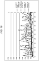
- FIG. 19 is a diagram illustrating information related to (a part of) a combination of 309 sets of NC 1 candidate code and NC 2 candidate code.
- FIG. 20 is a diagram illustrating an example of a first pattern NC 1 and a second pattern NC 2 .
- FIG. 21 is a diagram for describing an example of Run_out.
- FIG. 22 is a diagram for describing an example of a sync detection process performed by a sync detecting unit 61 .
- FIG. 23 is a flowchart illustrating an example of a sync detection process performed by a sync detecting unit 61 .
- FIG. 24 is a diagram for describing an example of recording of an FS in two adjacent tracks of an optical disc 16 .
- FIG. 25 is a diagram for describing a partial response maximum likelihood (PRML) of a code in which a constraint length (ISI length) is 11, and a minimum run d is 1 (2T in an NRZ expression).
- PRML partial response maximum likelihood
- FIG. 26 is a diagram illustrating an example of a trellis used for a PRML of a code in which a constraint length is 11, and a minimum run d is 1.
- FIG. 27 is a diagram illustrating an example of an FS.
- FIG. 28 is a diagram illustrating an example of an FS in a case where there is no clock shift for FSs of 6 patterns and an FS in a case where there is a clock shift.
- FIG. 29 is a diagram illustrating a relation of extended FS code strings FSA #i, FSB #i, and FSC #i.
- FIG. 31 is a diagram for describing a special state.
- FIG. 32 is a block diagram illustrating a configuration example of a restoring unit 35 .
- FIG. 33 is a block diagram illustrating a configuration example of an ACS unit 113 i .
- FIG. 34 is a flowchart illustrating an example of a time information generation process performed by a time information generating unit 62 of a code processing unit 38 .
- FIG. 35 is a flowchart for describing a maximum likelihood decoding process performed by a restoring unit 35 serving as a maximum likelihood decoding apparatus.
- FIG. 36 is a diagram illustrating a specific example of a maximum likelihood decoding process performed in accordance with an extended time-variant trellis.
- FIG. 37 is a diagram for describing detection of a clock shift and generation of a data gate signal.
- FIG. 38 is a diagram for describing another example of a frame constructed by a DCC adding unit 12 .
- FIG. 39 is a diagram for describing an example of channel coding performed on a frame cluster by a channel coding unit 13 .
- FIG. 40 is a diagram illustrating a configuration example of an FS of 30T.
- FIG. 41 is a diagram for describing another example of a RUB constructed by a RUB constructing unit 14 .
- FIG. 42 is a diagram for describing an example of a shortened RUB constructed by a RUB constructing unit 14 .
- FIG. 43 is a diagram illustrating a configuration example of Run_in of 4,614 T.
- FIG. 44 is a diagram illustrating an example of a nc 0 pattern and terminal patterns tp 1 and tp 2 .
- FIG. 45 is a diagram illustrating a configuration example of an auxiliary control pattern APCSY of 804T.
- FIG. 46 is a diagram illustrating an example of a nc 1 pattern and a nc 2 pattern of 60T arranged at a head of an auxiliary control pattern APCSY.
- FIG. 47 is a diagram illustrating a configuration example of Run_out and additional Run_out.
- FIG. 48 is a flowchart for describing an example of a sync detection process performed by a sync detecting unit 61 in a case where a RUB constructing unit 14 constructs a standard RUB.
- FIG. 49 is a block diagram illustrating a configuration example of one embodiment of a computer to which the present technology is applied.
- FIG. 1 is a block diagram illustrating a configuration example of one embodiment of a recording/reproducing apparatus to which the present technology is applied.
- the recording/reproducing apparatus includes an Error Correction Coding (ECC) processing unit 11 , a Direct Current Control (DCC) adding unit 12 , a channel coding unit 13 , a Recording Unit Block (RUB) constructing unit 14 , a recording/reproducing system 15 , an optical disc 16 , a signal processing unit 17 , a channel decoding unit 18 , a DCC deleting unit 19 , an ECC processing unit 20 , and a control unit 21 .
- ECC Error Correction Coding
- DCC Direct Current Control
- RAB Recording Unit Block
- User data (content such as images or sounds, a computer programs, and other various kinds of data) to be recorded on the optical disc 16 is supplied to the ECC processing unit 11 .
- the ECC processing unit 11 constructs ECC target data including user data of a predetermined unit which is a target of an ECC process for each predetermined unit of user data.
- the ECC processing unit 11 constructs an ECC block by executing the ECC process for adding a parity to the ECC target data, and supplies the ECC block to the DCC adding unit 12 .
- the DCC adding unit 12 divides the ECC block from the ECC processing unit 11 into row data serving as data of a predetermined unit and adds (inserts) a DCC bit for direct current (DC) control to each piece of row data.
- the DCC adding unit 12 constructs a frame by adding necessary data such as a frame sync (FS) indicating a head (or an end) of a frame to the row data to which the DCC bit is added, and supplies the frame to the channel coding unit 13 .
- FS frame sync
- the channel coding unit 13 encodes the frame from the DCC adding unit 12 into a predetermined channel code and supplies the encoded frame to the RUB constructing unit 14 .
- the channel code for example, a parity-complementary word assignment (PCWA) code, in particular, for example, a PCWA 110 code, an arbitrary run-length limited (RLL) code, or the like can be employed.
- PCWA 110 code is a binary code, but a multi-valued code of three or more values can be employed as the channel code.
- an RLL code in which a minimum run is d, and a maximum run is k is referred to as a (d,k) RLL code.
- the PCWA 110 code is a code having a code rate of 2 ⁇ 3 at which 2-bit information is encoded into a 3-bit code and is a (1,10) RLL code in which the minimum run d is 1, and the maximum run k is 10 in a non return to zero inversion (NRZI) expression.
- the PCWA 110 code is described, for example, in Japanese Patent No. 4998472.
- the minimum run d and the maximum run k of the PCWA 110 are 2T and 11T, respectively.
- runs by the NRZI expression are indicated without T, and runs (and sizes) by the NRZ expression are indicated with T.
- the RUB constructing unit 14 constructs a RUB by adding Run_in and Run_out indicating the head and the end of the ECC block, respectively, to a set of frames (frames encoded into a channel code) (a frame cluster to be described later) from the channel coding unit 13 , and supplies the RUB to the recording/reproducing system 15 .
- the recording/reproducing system 15 is constructed by a pickup or the like (not illustrated).
- the recording/reproducing system 15 functions as a recording unit that irradiates the optical disc 16 with light such as laser light, forms a mark, and records data in the optical disc 16 .
- the recording/reproducing system 15 functions as a reproducing unit that irradiates the optical disc 16 with the laser light, receives reflected light from the optical disc 16 against the laser light, outputs a reproduction signal corresponding to the reflected light, and reproduces data recorded in the optical disc 16 .
- the recording/reproducing system 15 irradiates the optical disc 16 with laser light in accordance with the RUB from the RUB constructing unit 14 , and records the RUB in the optical disc 16 . Further, the recording/reproducing system 15 irradiates the optical disc 16 with the laser light, reproduces the reproduction signal (a radio frequency (RF) signal) corresponding to the RUB or the like recorded in the optical disc 16 , and supplies the reproduction signal to the signal processing unit 17 .
- RF radio frequency
- the optical disc 16 is a sort of disk-type recording medium, and a land (track) and a groove (track) are formed as tracks at adjacent positions.
- the groove is a groove-like track and wobbles for addressing.
- the land is a track sandwiched between two (adjacent) grooves.
- optical disc 16 in order to record data with high density, data is recorded in both the land and the groove (marks are formed).
- the reproduction signal having the track TK 0 as the reproduction target includes a crosstalk component caused by the crosstalk from the tracks TK 1 and TK 2 adjacent to the track TK 0 , and the reproduction signal having the track TK 0 as the reproduction target is deformed from an original waveform (a waveform with no crosstalk).
- the signal processing unit 17 to be described later performs crosstalk cancellation (hereinafter also referred to as cross talk cancel (XTC)) of canceling the crosstalk (component) of the reproduction signal as one of signal processing, and obtains the reproduction signal of the original waveform.
- crosstalk cancel hereinafter also referred to as cross talk cancel (XTC)
- a light receiving surface of a light receiving element that receives the reflected light from the optical disc 16 is divided into, for example, three regions in (a direction corresponding to) the radial direction of the optical disc 16 .
- the reflected light from the optical disc 16 entering the regions are received, and signal components rs 0 , rs 1 , and rs 2 corresponding to the reflected light are obtained.
- the recording/reproducing system 15 outputs the signal components rs 0 , rs 1 , and rs 2 as the reproduction signals.
- the signal component rs 0 is a signal component mainly corresponding to the reflected light from the track TK 0 of the reproduction target. Further, the signal component rs 1 is a signal component mainly corresponding to the reflected light from (at least a part of) the track TK 1 adjacent to one of an inner circumference and an outer circumference of the track TK 0 , and the signal component rs 2 is a signal component mainly corresponding to the reflected light from (at least a part of) the track TK 2 adjacent to the other of the inner circumference and the outer circumference of the track TK 0 .
- the reproduction signal obtained by the recording/reproducing system 15 includes, for example, the signal components rs 0 , rs 1 , and rs 2 serving as a plurality of signal components corresponding to a plurality of regions (for example, the tracks TK 0 , TK 1 , and TK 2 ) which differ in the radial direction of the optical disc 16 .
- the light receiving surface of the light receiving element of the recording/reproducing system 15 is divided into three regions in the radial direction of the optical disc 16 , but the method of dividing the light receiving surface of the light receiving element is not limited thereto.
- the light receiving surface of the light receiving element can be divided into, for example, 4 or more regions in the radial direction of the optical disc 16 .
- the light receiving surface of the light receiving element can be divided into an arbitrary number of regions (a plurality of regions) by dividing it in the radial direction and the track direction of the optical disc 16 .
- the recording/reproducing system 15 can obtain signal components which are equal in number to a division number of the light receiving surface of the light receiving element as the reproduction signal.
- the reflected light from the optical disc 16 may be received by a plurality of light receiving elements.
- a signal obtained by receiving the reflected light from the optical disc 16 through one light receiving element in which the light receiving surface is not divided can be employed.
- the signal processing unit 17 restores the frame of the channel code similar to that output from the channel coding unit 13 , and supplies the restored frame to the channel decoding unit 18 .
- the signal processing unit 17 by performing the signal processing of the reproduction signal, the signal processing unit 17 generates frame data which is data of a portion of the frame of the channel code other than the FS, that is, a data gate signal indicating an interval of the row data to which the DCC bit is added, and supplies the frame data to the channel decoding unit 18 .
- the channel decoding unit 18 extracts, for example, the PCWA 110 code serving as the channel code which is the frame data of the interval indicated by the data gate signal similarly output from the signal processing unit 17 from the frame of the channel code output from the signal processing unit 17 . Further, the channel decoding unit 18 performs decoding (channel decoding) on the PCWA 110 code which is the frame data extracted from the frame, and supplies the frame data obtained by the decoding, that is, the row data to which the DCC bit is added to the DCC deleting unit 19 .
- decoding channel decoding
- the DCC deleting unit 19 deletes the DCC bit from the frame data from the channel decoding unit 18 and supplies the resulting row data to the ECC processing unit 20 .
- the ECC processing unit 20 collects the row data from the DCC deleting unit 19 and constructs an ECC block. Further, the ECC processing unit 20 executes the ECC process on the ECC block, corrects an error occurring in the ECC target data included in the ECC block, and outputs the user data included in the ECC target data.
- the control unit 21 controls the respective blocks constituting the recording/reproducing apparatus.
- the control unit 21 includes a register group 21 A therein.
- the register group 21 A stores (sets) various kinds of information such as command and the like in response to, for example, a manipulation of a manipulating unit (not illustrated) or the like.
- the control unit 21 controls the respective blocks constituting the recording/reproducing apparatus in accordance with a storage value (a setting value) of the register group 21 A.
- the recording/reproducing apparatus is configured as an apparatus that performs both reproduction and recording but may be configured as a dedicated reproducing apparatus that performs only reproduction or a dedicated recording apparatus that performs only recording.
- the recording/reproducing apparatus may be configured such that the optical disc 16 is installed in advance or may be configured such that the optical disc 16 is removably attached.
- the ECC processing unit 11 to the RUB constructing unit 14 and the signal processing unit 17 to the control unit 21 constituting the recording/reproducing apparatus of FIG. 1 can be constituted by one chip.
- FIG. 2 is a flowchart illustrating an example of a recording process in which the recording/reproducing apparatus of FIG. 1 records the user data in the optical disc 16 .
- step S 11 the ECC processing unit 11 constructs ECC target data including the user data using the user data supplied thereto. Further, the ECC processing unit 11 executes the ECC process to ECC target data, constructs an ECC block in which a parity is added to the ECC target data, and supplies the ECC block to the DCC adding unit 12 , and the process proceeds from step S 11 to step S 12 .
- step S 12 the DCC adding unit 12 divides the ECC block from the ECC processing unit 11 into row data, and constructs a frame by adding the DCC bit to each piece of row data and adding necessary data such as an FS.
- the DCC adding unit 12 supplies the frame to the channel coding unit 13 , and the process proceeds from step S 12 to step S 13 .
- step S 13 the channel coding unit 13 encodes the frame from the DCC adding unit 12 into a channel code such as the PCWA 110 code and supplies the encoded frame to the RUB constructing unit 14 , and the process proceeds to step S 14 .
- step S 14 the RUB constructing unit 14 receives the frames from the channel coding unit 13 , collects the frames obtained from one ECC block, and adds Run_in and Run_out to a set of frames.
- the RUB constructing unit 14 supplies the RUB to the recording/reproducing system 15 , and the process proceeds from step S 14 to step S 15 .
- step S 15 the recording/reproducing system 15 records the RUB in the optical disc 16 by irradiating the optical disc 16 with the laser light in accordance with the RUB from the RUB constructing unit 14 .
- FIG. 3 is a flowchart illustrating an example of a reproducing process in which the recording/reproducing apparatus of FIG. 1 reproduces the user data recorded in the optical disc 16 .
- step S 21 the recording/reproducing system 15 reproduces the reproduction signal corresponding to the RUB recorded in the optical disc 16 by irradiating the optical disc 16 with the laser light, and supplies the reproduction signal to the signal processing unit 17 , and the process proceeds to step S 22 .
- step S 22 the signal processing unit 17 performs signal processing on the reproduction signal from the recording/reproducing system 15 .
- the frame of the channel code and the data gate signal obtained by the signal processing on the reproduction signal are supplied from the signal processing unit 17 to the channel decoding unit 18 , and the process proceeds from step S 22 to step S 23 .
- step S 23 the channel decoding unit 18 extracts, for example, the PCWA 110 code serving as the channel code which is the frame data of the interval indicated by the data gate signal from the signal processing unit 17 from the frame of the channel code from the signal processing unit 17 . Further, the channel decoding unit 18 performs the channel decoding on the channel code which is the frame data extracted from the frame. Then, the channel decoding unit 18 supplies the frame data (the row data to which the DCC bit is added) obtained by the channel decoding to the DCC deleting unit 19 , and the process proceeds from step S 23 to step S 24 .
- the PCWA 110 code serving as the channel code which is the frame data of the interval indicated by the data gate signal from the signal processing unit 17 from the frame of the channel code from the signal processing unit 17 . Further, the channel decoding unit 18 performs the channel decoding on the channel code which is the frame data extracted from the frame. Then, the channel decoding unit 18 supplies the frame data (the row data to which the DCC bit is added) obtained by the channel decoding to the D
- step S 24 the DCC deleting unit 19 deletes the DCC bit from the frame data from the channel decoding unit 18 , supplies the resulting row data to the ECC processing unit 20 , and the process proceeds to step S 25 .
- step S 25 the ECC processing unit 20 collects the row data from the DCC deleting unit 19 and constructs the ECC block. Further, the ECC processing unit 20 executes the ECC process on the ECC block using the parity included in the ECC block, corrects the error of the ECC block, and outputs the user data included in the ECC target data of the ECC block.
- FIG. 4 is a block diagram illustrating a configuration example of the signal processing unit 17 of FIG. 1 .
- the signal processing unit 17 includes an analog to digital converter (ADC) 31 , a phase lock loop (PLL) 32 , a memory 33 , an adaptive equalizing unit 34 , a restoring unit 35 , a convolution unit 36 , an error calculating unit 37 , a code processing unit 38 , a high pass filter (HPF) 41 , and an auto gain controller (AGC) 42 .
- ADC analog to digital converter
- PLL phase lock loop
- PLL phase lock loop
- a memory 33 an adaptive equalizing unit 34 , a restoring unit 35 , a convolution unit 36 , an error calculating unit 37 , a code processing unit 38 , a high pass filter (HPF) 41 , and an auto gain controller (AGC) 42 .
- HPF high pass filter
- AGC auto gain controller
- the reproduction signal is supplied from the recording/reproducing system 15 to the ADC 31 .
- the ADC 31 performs AD conversion on an analog reproduction signal from the recording/reproducing system 15 in synchronization with a channel clock supplied from the PLL 32 , and outputs a resulting digital reproduction signal.
- the reproduction signal output from the ADC 31 is supplied to the PLL 32 and the memory 33 via the HPF 41 and the AGC 42 .
- the PLL 32 generates a clock synchronized with the reproduction signal supplied from the ADC 31 via the HPF 41 and the AGC 42 as the channel clock and supplies the generated clock to the ADC 31 and other necessary blocks constituting the recording/reproducing apparatus.
- the memory 33 temporarily stores, for example, the signal components rs 0 , rs 1 , and rs 2 serving as the reproduction signals supplied from the ADC 31 via the HPF 41 and the AGC 42 .
- the signal component rs 0 is a signal component mainly corresponding to the reflected light from the track TK 0 of the reproduction target.
- the signal component rs 1 is a signal component mainly corresponding to the reflected light from the track TK 1 adjacent to one of an inner circumference and an outer circumference of the track TK 0
- the signal component rs 2 is a signal component mainly corresponding to the reflected light from the track TK 2 adjacent to the other of the inner circumference and the outer circumference of the track TK 0 .
- the adaptive equalizing unit 34 adaptively equalizes the reproduction signal stored in the memory 33 , and supplies an equalized signal y obtained by equalizing the reproduction signal such as a partial response (PR) signal obtained from a desired PR channel to the restoring unit 35 and the error calculating unit 37 .
- an equalized signal y obtained by equalizing the reproduction signal such as a partial response (PR) signal obtained from a desired PR channel
- an error e of the equalized signal y is supplied from the error calculating unit 37 to the adaptive equalizing unit 34 .
- the equalization of the reproduction signal by the adaptive equalizing unit 34 is adaptively performed to reduce the error e from the error calculating unit 37 .
- the signal components rs 0 , rs 1 , and rs 2 serving as the reproduction signals stored in the memory 33 are independently equalized, and the equalized signal y is obtained by adding the equalization results of the signal components rs 0 , rs 1 , and rs 2 .
- the adaptive equalizing unit 34 it is possible to equalize a signal obtained by synthesizing (adding) the signal components rs 0 , rs 1 , and rs 2 serving as the reproduction signals without independently equalizing the signal components rs 0 , rs 1 , and rs 2 .
- the restoring unit 35 restores the PCWA 110 code (frame) or the like which is the channel code from the equalized signal y by performing the maximum likelihood decoding or the like on the equalized signal y from the adaptive equalizing unit 34 , and supplies the restoration result to the channel decoding unit 18 , the convolution unit 36 , and the code processing unit 38 .
- the restoring unit 35 restores the FS by performing the maximum likelihood decoding only on the FS at the head of the frame in the maximum likelihood decoding on the equalized signal y in accordance with a time-variant trellis for the FS in which a state and state transition are limited in accordance with a time.
- the maximum likelihood decoding for a portion other than the FS can be performed in accordance with the time-variant trellis prepared for the portion.
- the restoration of the PCWA 110 code other than the FS in the restoring unit 35 can be performed in accordance with a method other than the maximum likelihood decoding, that is, for example, binarization according to a threshold value process or the like.
- the convolution unit 36 convolutes the restoration result from the restoring unit 35 and an impulse response of a desired PR channel, generates a target signal serving as a target of the equalized signal y which is the equalization result of the adaptive equalizing unit 34 , and supplies the target signal to the error calculating unit 37 .
- the error calculating unit 37 obtains the error e of the equalized signal y from the adaptive equalizing unit 34 with respect to the target signal from the convolution unit 36 and supplies the error e to the adaptive equalizing unit 34 .
- Run_in included in the RUB recorded in the optical disc 16 is a known pattern.
- the target signal of the equalized signal y obtained by equalizing the reproduction signal of the known pattern is obtained by the convolution of the restoration result restored from the equalized signal y and the impulse response of the desired PR channel and can be obtained by convolution of the known pattern and an impulse response of a desired PR channel as well.
- the code processing unit 38 By processing the restoration result from the restoring unit 35 , the code processing unit 38 generates time information used for the maximum likelihood decoding according to the time-variant trellis in the restoring unit 35 , and supplies the time information to the restoring unit 35 . In there storing unit 35 , the maximum likelihood decoding for the FS is performed using the time information from the code processing unit 38 .
- the code processing unit 38 in response to the restoration result from the restoring unit 35 , the code processing unit 38 generates the data gate signal and supplies the data gate signal to the channel decoding unit 18 .
- the HPF 41 filters the reproduction signal output from the ADC 31 , cuts off a direct current (DC) component of the reproduction signal, and supplies the resulting signal to the AGC 42 .
- DC direct current
- the AGC 42 performs an auto gain control (AGC) process of adjusting a gain of the reproduction signal from the HPF 41 , and supplies the resulting signal to the PLL 32 and the memory 33 .
- AGC auto gain control
- FIG. 5 is a block diagram illustrating a configuration example of the adaptive equalizing unit 34 of FIG. 4 .
- the adaptive equalizing unit 34 has three adaptive equalizers 51 0 , 51 1 , and 51 2 which are equal in number to the signal components rs 0 , rs 1 , and rs 2 serving as the reproduction signals output by the recording/reproducing system 15 and an adding unit 52 .
- the adaptive equalizer 51 i includes, for example, a finite impulse response (FIR) filter, and performs equalization by filtering the signal component rs #i from the memory 33 through the FIR filter.
- the adaptive equalizer 51 i supplies an equalization component y #i which is the equalization result of the signaling component rs #i to the adding unit 52 .
- the error e of the equalized signal y with respect to the target signal is supplied from the error calculating unit 37 to the adaptive equalizer 51 i .
- the adaptive equalizer 51 i adaptively equalizes the signal component rs #i by adjusting a tap coefficient of the FIR filter that performs the equalization by, for example, ⁇ e ⁇ a (“a” is a predetermined coefficient) in accordance with the error e from the error calculating unit 37 .
- the adjusted tap coefficient is set to reduce a square error of the equalized signal y with respect to the target signal.
- the adaptive equalizer 51 i performs the equalization of the signal component rs #i using the tap coefficient that reduces the error e between the equalized signal y and the target signal.
- the adaptive equalizing unit 34 having the above configuration performs the crosstalk cancellation (XTC) as follows.
- the adaptive equalizer 51 i sets the tap coefficient of the FIR filter in accordance with the error e from the error calculating unit 37 . Further, in the adaptive equalizer 51 i , the signal component rs #i is filtered by the FIR filter and equalized independently.
- the adding unit 52 adds the equalization components y # 0 to y # 2 which are equalization results of the signal components rs # 0 to rs # 2 obtained by the adaptive equalizer 51 0 to 51 2 , removes the crosstalk component from the reproduction signal from the optical disc 16 , and obtains the equalized signal y as if it passed through the desired PR channel.
- the process of adjusting the tap coefficient of the FIR filter to reduce the error e of the equalized signal y in the adaptive equalizer 51 i as described above is also referred to as XTC learning. Since the tap coefficient is adjusted to reduce the square error of the equalized signal y with respect to the target signal in the XTC learning as described above, the XTC learning is least mean square (LMS) learning.
- LMS least mean square
- FIG. 6 is a block diagram illustrating a configuration example of the code processing unit 38 of FIG. 4 .
- the code processing unit 38 has a sync detecting unit 61 , a time information generating unit 62 , a clock shift detecting unit 63 , and a data gate signal generating unit 64 .
- the PCWA 110 code or the like serving as the restoration result is supplied from the restoring unit 35 to the sync detecting unit 61 .
- the sync detecting unit 61 detects a predetermined pattern such as a synchronization pattern syn 0 for synchronization from the restoration result from the restoring unit 35 and generates an FS gate signal indicating the interval of the FS at the head of the frame included in equalized signal y supplied from the adaptive equalizing unit 34 to the restoring unit 35 in accordance with the detection result.
- the sync detecting unit 61 then supplies the FS gate signal to the time information generating unit 62 .
- the time information generating unit 62 recognizes a position (a timing and an interval) of the FS from the FS gate signal from the sync detecting unit 61 . Further, the time information generating unit 62 counts a time based on the position of the FS in synchronization with the channel clock generated by the PLL 32 , and supplies counting information to the restoring unit 35 as time information.
- the restoration result is supplied from the restoring unit 35 to the clock shift detecting unit 63 .
- the clock shift detecting unit 63 detects (a position shift of data reproduced from the optical disc 16 which is caused by) the clock shift of the channel clock in accordance with (the restoration result of) the FS among the restoration results from the restoring unit 35 . Further, the clock shift detecting unit 63 supplies shift detection information indicating the detection result of the clock shift to the data gate signal generating unit 64 .
- the data gate signal generating unit 64 generates the data gate signal indicating the interval of the frame data subsequent to the FS at the head of the frame in accordance with the shift detection information from the clock shift detecting unit 63 and supplies the data gate signal to the channel decoding unit 18 .
- FIG. 7 is a diagram for describing an example of the ECC block constructed by the ECC processing unit 11 of FIG. 1 .
- the ECC processing unit 11 scrambles user data of 256 kilo byte (kB) including an error detection code (EDC), adds an address to the scrambling result, and constructs data of 262,740 byte (B) as ECC target data.
- ECC error detection code
- the ECC processing unit 11 forms ECC target data of 232 ⁇ 906 (horizontal ⁇ vertical) symbols.
- the ECC processing unit 11 constructs an ECC block of 236 ⁇ 982 symbols, for example, by adding a parity (parity inner (PI)) of 4 symbols to each row of the ECC target data of 232 ⁇ 906 symbols and adding a parity (parity outer (PO)) of 76 symbols to each column of the ECC target data.
- the ECC block constructed by the ECC processing unit 11 is a product code of a 10-bit symbol (a Galois field of 2 ⁇ circumflex over ( ) ⁇ 10).
- FIG. 8 is a diagram for describing an example of a frame constructed by the DCC adding unit 12 in FIG. 1 .
- the DCC adding unit 12 divides the ECC block into row data which is data of 2,360 dbits in one row.
- the frame data of 2,400 dbits includes 40 sets of data data #i and a DCC bit dcc #i.
- the DCC adding unit 12 adds the FS to the head of frame data, so that a frame frame #i in which the FS is arranged at the head, and the frame data is arranged following the FS is constructed.
- one ECC block includes 982 pieces (rows) of row data, 982 frames frame 1 to frame 982 are constructed from one ECC block.
- the FS is a pattern of 26 dbits, and thus one frame frame #i is data of 2,426 dbits including the FS of 26 dbits and the frame data of 2,400 dbits.
- an FS of a first frame frame 1 among the 982 frames frame 1 to frame 982 obtained from one ECC block an FS of 20 dbits in which 6 dbits at the head of the FS of 26 dbits are omitted is employed.
- the first frame frame 1 among the 982 frames frame 1 to frame 982 obtained from one ECC block is data of 2,420 dbits.
- the DCC adding unit 12 adds an end code (EC) of data of 6 dbits (to be described later) constituting the FS to the end of the last frame frame 982 among the 982 frames frame 1 to frame 982 obtained from one ECC block.
- EC end code
- the DCC adding unit 12 constitutes a frame cluster including the 982 frames frame 1 to frame 982 and the EC, and supplies the frame cluster to the channel coding unit 13 ( FIG. 1 ).
- FIG. 9 is a diagram for describing an example of the RUB constructed by the RUB constructing unit 14 in FIG. 1 .
- the channel coding unit 13 performs the channel coding of encoding the frame cluster supplied from the DCC adding unit 12 into, for example, the PCWA 110 code or the like. Since the PCWA 110 code is a code with a coding rate of 2/3 as described above with reference to FIG. 1 , the size (the number of bits) of the frame cluster after the channel coding is 3/2 times as large as that before the channel coding.
- each of the frames frame 2 to frame 982 other than the first frame frame 1 constituting the frame cluster is 3,639 channel bits (cbits) which is 3/2 times of 2,426 dbits.
- the size of the FS at the head of each of the frame frame 2 to frame 982 is 39T (39 cbits) which is 3/2 times of 26 dbits.
- the size of the first frame frame 1 constituting the frame cluster is 3,630 cbits which is 3/2 times of 2,420 dbits. Further, the size of the FS at the head of the frame frame 1 is 30T (30 cbits) which is 3/2 times of 20 dbits.
- the size of the EC constituting the frame cluster is 9T (9 cbits) which is 3/2 times of 6 dbits.
- the frame cluster encoded into the PCWA 110 code by the channel coding unit 13 is supplied to the RUB constructing unit 14 .
- the RUB constructing unit 14 constructs the RUB by adding Run_in indicating the head of the RUB and Run_out indicating the end of the RUB to the head and the end of the frame cluster from the channel coding unit 13 .
- the size of Run_in is, for example, 6,828T
- the size of Run_out is, for example, 450T.
- a total size 6,828T+450T of Run_in and Run_out is equal to 3,639 cbits ⁇ 2 corresponding to the two frames each having 3,639 cbits.
- Run_in is the EC of (the size of) 9T.
- the head of the FS of 39T at the head of each of the frames frame 2 to frame 982 is the EC of 9T as described later.
- the first frame frame 1 of the frame cluster is arranged in the RUB following Run_in.
- the FS of 30T of the frame frame 1 includes no EC of 9T arranged at the head of the FS of 39T of the other frames (frame 2 to frame 982 ), but since the EC is arranged at the end of Run_in, if the last EC of Run_in is considered, the FS of 39T is arranged at the head of the frame frame 1 , similarly to the other frames.
- FIG. 10 is a diagram for describing an overview of the PCWA 110 code.
- FIG. 10 is a diagram illustrating a code table and a replacement table used for encoding into the PCWA 110 code (PCWA 110 encoding).
- the PCWA 110 encoding there are five encoding states S 1 , S 2 , S 3 , S 4 , and S 5 , and in addition to information bits to be encoded, the PCWA 110 code is decided in accordance with the current encoding state.
- the PCWA 110 code is decided in accordance with the code table.
- a leftmost column indicates 2-bit information bits 00 , 01 , 10 , and 11 which are to undergo the PCWA 110 encoding.
- a number in brackets subsequent to the 2-bit information bits is a decimal notation of the 2-bit information bit.
- an uppermost row indicates (states which can be taken as) the current encoding states S 1 , S 2 , S 3 , S 4 , and S 5 .
- a field at a C-th column from the left and an R-th row from the top is also referred to as a field (C,R).
- PCWA 110 code is indicated by the NRZI expression unless otherwise set forth herein.
- the information bits 00 is encoded into a PCWA 110 code 000 described in the field ( 2 , 2 ) in accordance with the field ( 2 , 2 ) corresponding to the column (second column) in which the encoding state of the code table is the current state S 1 and the row (second row) in which the information bits are 00 .
- the encoding state transitions from the current state S 1 to the state S 3 described in the field ( 2 , 2 )
- the information bits which is a next target of the PCWA 110 encoding is, for example, 00 which is similar to the previous time
- the information bits 00 is encoded -into a PCWA 110 code 010 described in the field ( 4 , 2 ) in accordance with the field ( 4 , 2 ) corresponding to the column (fourth column) in which the encoding state of the code table is the current state S 3 and the row (second row) in which the information bits are 00 .
- the encoding state transitions from the current state S 3 to the state S 3 described in the column ( 4 , 2 ).
- the PCWA 110 encoding is performed in accordance with the code table on the basis of the current encoding state.
- the code sequence replacement is performed in accordance with the replacement table.
- a departure state indicates a state in which the PCWA 110 encoding of (a sequence of) 6-bit information bits starts, and an arrival state indicates a state reached after the PCWA 110 encoding of the 6-bit information bits.
- the 6-bit information bits 10 10 10 , 10 10 11 , 10 10 00 , and 10 10 01 are all encoded into a PCWA 110 code 000 000 000. Further, the arrival states after the PCWA 110 encoding of the 6-bit information bits 10 10 10 , 10 10 11 , 10 10 00 , and 10 10 01 are the states S 1 , S 2 , S 3 , and S 4 respectively.
- the PCWA 110 code 000 000 000 of each of the 6-bit information bits 10 10 10 , 10 10 11 , 10 10 00 , and - 10 10 01 is all replaced with a replacement code sequence 000 101 010 in accordance with the replacement table.
- the 6-bit information bits 00 10 10 , 00 10 11 , 00 10 00 , and 00 10 01 are all encoded into a PCWA 110 code 100 000 000.
- the arrival states after the PCWA 110 encoding of the 6-bit information bits 00 10 10 , 00 10 11 , 00 10 00 , and 00 10 01 are the states S 1 , S 2 , S 3 , and S 4 , respectively.
- the PCWA 110 code 100 000 000 of each of the 6-bit information bits 00 10 10 , 00 10 11 , 00 10 00 , and 00 10 01 is replaced with a replacement code sequence 100 101 010 in accordance with the replacement table.
- FIG. 11 is a diagram illustrating a configuration example of the FS of 39T of FIG. 9 .
- the FS of 39T (the FS after the PCWA encoding of the frames frame 2 to frame 982 or the like) is configured such that an EC of 9T, an FS entity including data of 2 pieces of data of 12T, and a begin code (BC) of 6T are arranged in the described order.
- the FS of 30T of the frame frame 1 ( FIG. 9 ) is configured such that there is no EC of 9T at the head of the FS of 39T.
- an end code (EC) table indicates a pattern serving as an EC
- a begin code (BC) table indicates a pattern serving as a BC.
- the EC and the BC are patterns having runs satisfying a code rule of the PCWA 110 code (a kind of (d,k) RLL code) serving as the channel code.
- the EC is a pattern of 9T in which the encoding state of the PCWA 110 encoding starts from each of the possible states S 1 to S 5 ( FIG. 10 ) and terminates in a specific one state.
- the state S 3 is employed as the specific one state. Note that the specific one state is not limited to the state S 3 .
- the encoding state transitions from the state S 1 to the states S 3 , S 1 , and S 3 in the described order and terminates (ends) in the state S 3 .
- the encoding state transitions from the state S 2 to the states S 3 , S 1 , and S 3 in the described order and terminates in the state S 3 .
- the encoding state transitions from the state S 3 to the states S 3 , S 1 , and S 3 in the described order and terminates in the state S 3 .
- the encoding state transitions from the state S 4 to the states S 3 , S 1 , and S 3 in the described order and terminates in the state S 3 .
- the encoding state transitions from the state S 5 to the states S 2 , S 1 , and S 3 in the described order and terminates in the state S 3 .
- the encoding state transitions from the state S 1 to the state S 3 in accordance with the code table ( FIG. 10 ) through the PCWA 110 encoding of the first 2-bit information bits 00 among the 6 bits information bits (Data) 00 10 00 indicated by ec 1 in the EC table.
- the encoding state transitions to the state S 3 after the PCWA 110 encoding of the first 2-bit information bits 00 of the EC.
- the PCWA 110 code 000 000 000 is obtained in the PCWA 110 encoding in which the transition from the departure state S 1 to the arrival state S 3 (the transition in the order of the states S 1 , S 3 , S 1 , and S 3 ).
- the PCWA 110 code 000 000 000 is replaced with the replacement code sequence 000 101 010 as illustrated in (a fourth row from the top of) the replacement table of FIG. 10 .
- the PCWA 110 code 000 obtained by the PCWA 110 encoding of the first 2-bit information bits 00 of the EC (the first PCWA 110 code 000 indicated by ec 1 in the EC table) is replaced with last 3 bits 010 of the replacement code sequence 000 101 010.
- the EC of 9T (Code) is 000 010 000 as described above, but in a case where the replacement with the replacement code sequence 000 101 010 is performed, the EC (Code) of 9T is 010 010 000 in which the first 3 bits 000 of 000 010 000 are replaced with the last 3 bits 010 of the replacement code sequence 000 101 010.
- the EC in a case where the encoding state is the state S 1 , the EC may be 000 010 000 or may be 010 010 000.
- the EC described above is a pattern in which the last run is 4 or 3 in the NRZI expression (5T or 4T in the NRZ expression).
- the ECs indicated by ec 1 to ec 4 are patterns having the last run of 4 (5T in the NRZ expression), and the EC indicated by ec 5 is a pattern having the last run of 3 (4T in the NRZ expression).
- the BC is a pattern of 6T in which the encoding state of the PCWA 110 encoding starts from a predetermined one state among the possible states S 1 to S 5 ( FIG. 10 ).
- the state S 5 is employed as the predetermined one state. Note that the predetermined one state is not limited to the state S 5 .
- 100 001 is employed as the BC of 6T ((Code) after the PCWA 110 encoding).
- the PCWA 110 code 100 001 serving as BC is a pattern in which a first run is 4 (5T in the NRZ expression).
- the encoding state transitions from the state S 5 to the states S 2 and S 2 in the described order.
- the encoding state becomes the state S 2 when the PCWA 110 encoding of data immediately after the BC is performed
- the data immediately after the BC is encoded into the PCWA 110 code 001 or 000 in accordance with the encoding table ( FIG. 10 ).
- the BC is followed by a pattern in which the run is at least 2 or 3 (3T or 4T in the NRZ expression).
- the FS is arranged at the head of the frame, and the EC is arranged after the last frame frame 982 . Therefore, the last BC of the FS is arranged immediately before the frame data subsequent to the FS of the frame, and the first EC of the FS of the next frame or the EC arranged after the last frame frame 982 is arranged immediately after the frame data.
- the frame data is sandwiched between the BC and the EC, and the RUB has a data structure in which the BC, the frame data, and the EC are arranged in the described order.
- the encoding state starts from the state S 5 and terminates in the state S 3 .
- a relation between whether the number of edges of the frame data before the PCWA 110 encoding, that is, the number of 1s in the NRZI expression is an odd number or an even number and whether the number of edges of the frame data after the PCWA 110 encoding is an odd number or an even number is constant.
- the number of edges of the frame data after PCWA 110 encoding is an even number. Further, in a case where the number of edges of the frame data before PCWA 110 encoding is an even number, the number of edges of the frame data after PCWA 110 encoding is an odd number.
- DC control can be performed by adding the DCC bit to the frame data (row data) before the PCWA 110 encoding.
- a pattern in which a pattern of a run of 12T is repeated three times or more or a pattern in which a pattern of a run larger than 12T is repeated twice or more can be employed as the FS entity.
- the FS has a data structure in which the FS entity with the run of 12T is sandwiched between the EC with the run of 4T or 5T which is about half 12T and the BC with the run of 5T. According to such data structure, detection performance of the FS entity and eventually the FS can be improved by controlling turbulence of the waveform of the reproduction signal caused by influence of intersymbol interference (ISI) from the EC before the FS entity or data before the EC and the BC after the FS entity or data after the BC.
- ISI intersymbol interference
- FIG. 12 is a diagram illustrating a configuration example of Run_in of 6,828T in FIG. 9 .
- an archival disc (AD) 1 is proposed as an optical disc capable of recording data with high density.
- Run_ins recorded in the land and the groove which are adjacent are not patterns in which a cross correlation is zero but small patterns with a size of 60 cbits, it is difficult to perform the XTC learning sufficiently through such Run_ins.
- the XTC learning, gain recovery, and timing recovery are performed using the reproduction signal of Run_in or the reproduction signal of the user data.
- the XTC learning a gain adjustment in the AGC 42 ( FIG. 4 )
- the timing recovery an adjustment of the channel clock in the PLL 32 ( FIG. 4 ) can be performed using the reproduction signal of Run_in and the reproduction signal of the frame.
- the reproduction signal of Run_in be a signal having a characteristic similar to that of the reproduction signal of the frame.
- the frame particularly, the frame data includes relatively random user data
- the cross correlation between frame data of the two adjacent tracks tends to be zero or a small value close to zero.
- Run_in of the optical disc 16 is configured such that the synchronization patterns are recorded in two adjacent tracks with a predetermined amount of shift in the track direction.
- FIG. 12 illustrates an example of Run_ins recorded in the two adjacent tracks of the optical disc 16 .
- FIG. 12 illustrates Run_in recorded in a land L (hereinafter also referred to as land Run_in) and Run_in recorded in a groove G (hereinafter also referred to as groove Run_in) in one of the inner circumference side and the outer circumference side of the land L.
- land Run_in a land L
- groove Run_in a groove G
- the land L and the groove G in at least one of the inner circumference side or the outer circumference side of the land L are paired.
- Run_ins (eventually the RUBs) are recorded in a pair of land L and groove G side by side at the same position in the track direction.
- FIG. 12 illustrates Run_in of a pair of land L and of groove G.
- Run_in is a pattern of 6,828T, and is configured such that a preamble of 5,880T and a sync area of 948T are arranged from the head.
- the preamble and the sync area of land Run_in are also referred to as an A pattern preamble and an A pattern sync area, respectively.
- the preamble and the sync area of groove Run_in are also referred to as a B pattern preamble and a B pattern sync area, respectively.
- the configurations of land Run_in and groove Run_in may be reversed.
- land Run_in can include the B pattern preamble and the B pattern sync area
- groove Run_in can include the A pattern preamble and the A pattern sync area.
- Run_in has the synchronization pattern syn 0 .
- the synchronization pattern syn 0 has a pattern of 60T of 6T/12T ⁇ 4/6T.
- 6T/12T ⁇ 4/6T indicates a pattern in which a run of 6T is arranged, then 4 runs of 12T are arranged, and then a run of 6T is arranged.
- the preamble is configured by alternately arranging the synchronization pattern syn 0 of (the size of) 60T and the A pattern or the B pattern serving as a predetermined pattern of 360T.
- the A pattern preamble of land Run_in is constructed by alternately arranging the synchronization pattern syn 0 and the A pattern.
- the B pattern preamble of groove Run_in is constructed by alternately arranging the synchronization pattern syn 0 and the B pattern.
- the synchronization pattern syn 0 is arranged with a shift of 60T which is the length (size) of the synchronization pattern syn 0 .
- the B pattern preamble for example, only 13 sets each including the synchronization pattern syn 0 of 60T and the B pattern of 360T are arranged from a position shifted from the head by 60T which is the length of the synchronization pattern syn 0 are arranged.
- a pattern of 60T which is the same length as the synchronization pattern syn 0 at the end of the B pattern is referred to as a B 1 pattern
- patterns of portions excluding the B 1 pattern on the head side of the B pattern is referred to as a B 0 pattern
- the B 1 pattern is arranged at the head of the B pattern preamble.
- the synchronization pattern syn 0 and a B 0 pattern are arranged after the 13 sets each including the synchronization pattern syn 0 and the B pattern.
- the B pattern preamble has a data structure in which the arrangement of the 14 sets each including the synchronization pattern syn 0 and the B pattern is rotated in the right direction by 60T which is the length of the synchronization pattern syn 0 .
- the synchronization pattern syn 0 is arranged at a position shifted from the position of the synchronization pattern syn 0 of the A pattern preamble by 60T which is the length of the synchronization pattern syn 0 .
- the B pattern arranged in the B pattern preamble is also arranged at a position shifted from the position of the A pattern arranged in the A pattern preamble by 60T which is the length of the synchronization pattern syn 0 .
- the A pattern and the B pattern are, for example, the PCWA 110 codes serving as the channel code of 360 cbits (360T) in which the DC control is performed with a period of 90 cbits, for example.
- the A pattern and the B pattern are patterns in which the number of edges (the number of 1s in the NRZI expression) is an odd number, and a terminal digital sum value (DSV) is zero.
- the terminal DSV of the pattern is a sum of all bits constituting the pattern which are obtained by converting 1 among bits constituting the pattern of the NRZ expression into +1 and converting 0 into ⁇ 1.
- the B pattern is a pattern in which a cross correlation between the synchronization pattern syn 0 and the A pattern and a corresponding interval of the B pattern preamble is zero in the interval of 420T of the synchronization pattern syn 0 and the A pattern.
- the cross correlation between the A pattern preamble and the B pattern preamble is zero in the interval of 420T at an arbitrary position.
- the tendency of the DC component occurring in the reproduction signal of the preamble, an offset, a gain, or the like is similar to the tendency of the DC component or the like occurring in the reproduction signal of the frame data in which the cross correlation in the adjacent tracks tends to be zero or a small value close to zero.
- the reproduction signal of the preamble is a signal having a similar characteristic to that of the reproduction signal of the frame data.
- the sync area is configured by alternately arranging the synchronization pattern syn 0 of 60T and a zero correlation pattern NC 0 of 60T in which the cross correlation with the synchronization pattern syn 0 is zero.
- the A pattern sync area of land Run_in is configured by alternately arranging the synchronization pattern syn 0 and the zero correlation pattern NC 0 .
- the B pattern sync area of groove Run_in is configured by alternately arranging the synchronization pattern syn 0 and the zero correlation pattern NC 0 .
- the synchronization pattern syn 0 is arranged with a shift of 60T which is the length of the synchronization pattern syn 0 .
- the B pattern sync area for example, only seven sets each including the zero correlation pattern NC 0 of 60T and the synchronization pattern syn 0 of 60T are arranged from the position shifted from the head by 60T which is the length of the synchronization pattern syn 0 or the zero correlation pattern NC 0 .
- the B 1 pattern of 60T is arranged at the head thereof, and a second pattern NC 2 of 48T is arranged at the end thereof.
- the first pattern NC 1 and the second pattern NC 2 are the PCWA 110 codes of 48 cbits (48T) in which the cross correlation is zero and are patterns in which the terminal DSV is zero.
- the EC is arranged at the ends of the first pattern NC 1 and the second pattern NC 2 . Therefore, Run_in terminates with the EC.
- the B 1 pattern is arranged at the head of the B pattern sync area. Since the synchronization pattern syn 0 and the B 0 pattern are arranged at the end of the B pattern preamble before the B pattern sync area, if seen from the last synchronization pattern syn 0 of the B pattern preamble, the B 0 pattern and the B 1 pattern, that is, the B patterns are arranged after the synchronization pattern syn 0 .
- the synchronization pattern syn 0 is arranged at a position shifted by 60T which is the length of the synchronization pattern syn 0 , similarly to the A pattern preamble and the B pattern preamble.
- the synchronization pattern syn 0 of one sync area out of the A pattern sync area and the B pattern sync area is adjacent to the zero correlation pattern NC 0 in which the cross correlation of the other sync area with the synchronization pattern syn 0 is zero.
- the reproduction signal of the sync area becomes a signal having a similar characteristic to that of the reproduction signal of the frame data, similarly the reproduction signal of the preamble.
- the reproduction signals of all Run_ins become a signal having a similar characteristic to that of the reproduction signal of the frame data.
- the shift amount of the synchronization pattern syn 0 of a pair of land L and groove G is not limited to the length of the synchronization pattern syn 0 and may be shorter than the length of the synchronization pattern syn 0 or larger than the length of the synchronization pattern syn 0 .
- the synchronization patterns syn 0 of the land L and the groove G of the pair may be shifted to partially overlaps (be adjacent).
- the synchronization patterns syn 0 of a pair of land L and groove G may be shifted not to overlap.
- an n-th track from the inner circumference side of the optical disc 16 is referred to as a track TK(n).
- a track TK(n) As a case where the synchronization pattern is shifted in the track direction with a certain amount of shift in (a pair of) two adjacent tracks, there area case where the synchronization pattern is shifted by a certain amount of shift in an arbitrary -track TK(n) of the optical disc 16 , a track TK(n ⁇ 1) on the inner circumference side adjacent to the track TK(n), and a track TK(n+1) on the outer circumference side and a case where the synchronization pattern is shifted by a certain amount of shift in an odd-numbered track TK(2n′ ⁇ 1) of the optical disc 16 and an even-numbered track TK(2n′) on the outer circumference side of the track TK(2n′ ⁇ 1).
- FIG. 13 is a diagram for describing an example of the synchronization pattern syn 0 and the zero correlation pattern NC 0 .
- a of FIG. 13 illustrates an example (of the reproduction signal) of the synchronization pattern syn 0 .
- the synchronization pattern syn 0 has the pattern of 60T of 6T/12T ⁇ 4/6T.
- the synchronization pattern syn 0 is a pattern of 60T in which the sync entity of the pattern of 12T ⁇ 4 is sandwiched between additional patterns of 6T arranged before and after the sync entity of the pattern of 12T ⁇ 4.
- the synchronization pattern syn 0 is recorded in (a pair of) two adjacent tracks with a shift of the length of the synchronization pattern syn 0 , but the additional patterns of 6T are arranged before and after the sync entity of the synchronization pattern syn 0 , a certain distance is secured between the sync entities of the synchronization pattern syn 0 recorded in the two adjacent tracks with a shift by the additional patterns.
- FIG. 13 illustrates an example of the zero correlation pattern NC 0 .
- the zero correlation pattern NC 0 is, for example, a pattern of 60T of 3T ⁇ 2/(4T/2T/2T/4T) ⁇ 4/3T ⁇ 2, and is a pattern in which the cross correlation with the synchronization pattern syn 0 is zero.
- the zero correlation pattern NC 0 is a pattern in which the number of edges (number of 1 in the NRZI expression) is an even number, and the terminal DSV is zero.
- FIG. 14 is a diagram for describing the A pattern and the B pattern arranged in Run_in of FIG. 12 .
- the RUB constructed by the RUB constructing unit 14 of FIG. 1 can be indicated by the NRZI expression in which an inversion of data (bit) is indicated by i, and a non-inversion is indicated by 0.
- the RUB is recorded in the optical disc 16 as data of ⁇ 1 of the NRZ expression which has an initial value starting with +1 or ⁇ 1 and is inverted in a case where data of the RUB of the NRZI expression is 1.
- DSV(K) indicates a DSV from a 1-st bit to a K-th bit of the pattern in which the DSV is obtained.
- ⁇ indicates a summation obtained by replacing k with an integer ranging from 1 to K.
- NRZ(k) indicates a value (+1 or ⁇ 1) of the k-th bit of the pattern in which the DSV is obtained.
- XC(K) indicates the cross correlation from the 1-st bit to the k-th bit of the patterns P 1 and P 2 .
- ⁇ indicates a summation obtained by replacing k with an integer ranging from 1 to K.
- P 1 (k) and P 2 (k) indicate values of the k-th bit (+1 or ⁇ 1) of the patterns P 1 and P 2 , respectively.
- data of 230 dbits is obtained using a uniform random number, and the DCC bit is added to the data of 230 dbits with the period of 59 dbits ( FIG. 8 ) which is the same period (DCC period) as the period with which the DCC bit is added to the frame.
- the addition of the DCC bit is performed so that an absolute value of the DSV is minimum (preferably, 0).
- the DCC bit is added to the data of 230 dbits at the period of 59 dbits, the DCC bits of 4 bits in total are added, and the data of 230 dbits is the data of 234 dbits.
- the PCWA 110 encoding into the PCWA 110 code which is the channel code is performed on the data of 234 dbits to which the DCC bit is added.
- the PCWA 110 encoding starts from the state S 5 , similarly to the BC ( FIG. 11 ) arranged immediately before the frame data.
- the PCWA 110 code of the 351 cbits is obtained.
- the PCWA 110 code of 9 cbits serving as the termination code is finally added to the PCWA 110 code of 351 cbits, so that the encoding state terminates in the state S 5 .
- the state transition of the encoding state by which the termination code of 9 cbits causing the encoding state to terminate in the state S 5 is obtained by adding it to the PCWA 110 code of 351 cbits, for example, the following five transitions are obtained from the code table of FIG. 10 .
- the first transition S 1 ⁇ 11/000 ⁇ S 2 ⁇ 01/001 ⁇ S 2 ⁇ 11/000 ⁇ S 5 among the state transitions (ST) indicates that, in a case where the encoding state is the state S 1 , the information bit 11 is encoded into the PCWA 110 code 000, transition to the state S 2 is performed, the information bits 01 is encoded into the PCWA 110 code 001 in the state S 2 , transition to the state S 2 is performed, the information bits 11 is encoded into the PCWA 110 code 000 in the state S 2 , and transition to the state S 5 is performed.
- the termination code causing the encoding state to terminate in the state S 5 is 000 001 000.
- the termination code of 9 cbits causing the encoding state to terminate in the state S 5 is 000 001 000 in a case where the encoding state is the state S 1
- the termination code of 9 cbits causing the encoding state to terminate in the state S 5 is 001 001 000 in a case where the encoding state is the state S 2
- the termination code of 9 cbits causing the encoding state to terminate in the state S 5 is 010 001 000 in a case where the encoding state is the state S 3
- the termination code of 9 cbits causing the encoding state to terminate in the state S 5 is 100 010 000 in a case where the encoding state is the state S 4
- the termination code of 9 cbits causing the encoding state to terminate in the state S 5 is 101 001 000 in a case where the encoding state is the state S 5 .
- the termination code 000 001 000 in a case where the encoding state is the state S 1 is added to the PCWA 110 code of 351 cbits, and the PCWA 110 code of 360 cbits obtained by the addition is caused to terminate in the state S 5 .
- PCWA 110 codes of 360 cbits obtained as described above for example, an integer number of PCWA 110 codes, or the like, as a predetermined number, 100 PCWA 110 codes in each which the DSV( 360 ) of Formula (1) serving as the terminal DSV is 0, the number of edges (the number of is in the NRZI expression) is an odd number, and one or more of runs of 11T which is the maximum run k of the PCWA 110 code are included are generated as candidates of the A pattern and the B pattern (hereinafter also referred to as A/B candidate codes).
- a combination of two A/B candidate codes is selected from the 100 A/B candidate codes, and the synchronization pattern syn 0 and the A pattern and the synchronization pattern syn 0 and the B pattern are constructed using one A/B candidate code out of the two A/B candidate codes as the A pattern and using the other A/B candidate code as the B pattern.
- the pattern in which the synchronization pattern syn 0 and the A pattern are repeatedly arranged and the pattern in which the synchronization pattern syn 0 and the B pattern are repeatedly arranged are arranged with a shift of the length of the synchronization pattern syn 0 , similarly to Run_in of FIG. 12 , and a combination of two A/B candidate codes in which XC( 420 ) of Formula (2) which is the cross correlation between the synchronization pattern syn 0 and the A pattern and the synchronization pattern syn 0 and the B pattern is zero in the interval of the synchronization pattern syn 0 and the A pattern is obtained.
- the A/B candidate code used as the A pattern in is also referred to as an A candidate code
- the A/B candidate code used as the B pattern is also referred to as a B candidate code.
- FIG. 14 illustrates information related to (some of) the 256 sets of combinations of the A candidate code and the B candidate code.
- a variance of the cross correlations XC( 1 ) to XC( 420 ) are illustrated as “variance of cross correlation” in the ascending order of the variances of the cross correlations XC( 1 ) to XC( 420 ) for (some of) the 256 sets of combinations of the A candidate code and the B candidate code.
- a variance of DSVs in which DSV( 1 ) to DSV( 360 ) of the A candidate code and DSV( 1 ), DSV( 2 ), . . . , and DSV( 360 ) of the B candidate code are combined is illustrated as “variance of DSV of each of A and B” in the ascending order of the variances of the cross correlations XC( 1 ) to XC( 420 ) for the 256 sets of combinations of the A candidate code and the B candidate code.
- a minimum value among distances between a pattern of a run of 11T included in the A candidate code and a pattern of a run of 11T included in the B candidate code (a shift amount of the pattern of 11T in the track direction is illustrated as “minimum distance” for the 256 sets of combinations of the A candidate code and the B candidate code.
- FIG. 15 is a diagram illustrating information related to the combinations of the A candidate code and the B candidate code in which the rankings of the variances of the cross correlations XC( 1 ) to XC( 420 ) in the ascending order come in first to fourth among the 256 sets of combinations of the A candidate code and the B candidate code described above with reference to FIG. 14 .
- A, B, C, and D of FIG. 15 indicate information related to combinations of the A candidate code and the B candidate code in the first place, the second place, the third place, and the fourth place, respectively.
- the DC component of the reproduction signal of Run_in have a similar characteristic to that of the DC component of the reproduction signal of the frame data, that is, for example, be small on the average.
- a combination of the A candidate code and the B candidate code in which DSV( 1 ) to DSV( 420 ) and the cross correlations XC( 1 ) to XC( 420 ) are small on the average can be employed among the combinations of the A candidate code and the B candidate code in which the variance of DSV( 1 ) to DSV( 420 ) is a threshold value TH 1 or less, and the variance of the cross correlations XC( 1 ) to XC( 420 ) is a threshold value TH 2 or less.
- the combination of the A candidate code and the B candidate code ranked fourth in D of FIG. 15 is a combination in which DSV( 1 ) to DSV( 420 ) of the synchronization pattern syn 0 and the A candidate code, DSV( 1 ) to DSV( 420 ) of the synchronization pattern syn 0 and the B candidate code, and the cross correlations XC( 1 ) to XC( 420 ) are small on the average.
- the combination of the A candidate code and the B candidate code at the fourth place in D of FIG. 15 can be employed as the A pattern and the B pattern.
- FIG. 16 is a diagram illustrating an example of the A pattern and the B pattern.
- FIG. 16 illustrates the combination of the A candidate code and the B candidate code ranked fourth in D of FIG. 15 .
- the A pattern and the B pattern are arranged with the synchronization pattern syn 0 similarly to a case where arranged in Run_in together.
- the synchronization pattern syn 0 and the A pattern are arranged in the described order
- the B pattern it is divided into the B 0 pattern and the B 1 pattern, and the B 1 pattern, the synchronization pattern syn 0 , and the B 0 pattern are arranged in the described order.
- a horizontal axis indicates a position (time) from the head of Run_in
- a vertical axis indicates a run length of data of ⁇ 1 of the NRZ expression that terminates at the position indicated by the horizontal axis.
- both the A pattern and the B pattern include one run of 11T, and the run of 11T included in the A pattern and the run of 11T included in the B pattern are relatively far away, for example.
- FIG. 17 is a diagram illustrating information related to the A pattern and the B pattern in FIG. 16 .
- the number of edges (the number of 1s in the NRZI expression) is an odd number.
- the synchronization pattern syn 0 and the A pattern are repeatedly arranged in the preamble of Run_in, but since the number of edges of the A pattern is an odd number, the polarity of DSV( 1 ) to DSV( 420 ) of the A pattern is reversed between an interval pd of 420T with the synchronization pattern syn 0 and the A pattern and a next interval pd+1 of 420T with the synchronization pattern syn 0 and the A pattern. The same applies to DSV( 1 ) to DSV( 420 ) of the B pattern.
- a of FIG. 17 illustrates “DSV of A”, “DSV of B”, and “cross correlation” in the interval pd of 420T with the synchronization pattern syn 0 and the A pattern
- B of FIG. 17 illustrates “DSV of A”, “DSV of B”, and “cross correlation” in the next interval pd+1 of 420T with the synchronization pattern syn 0 and the A pattern.
- FIG. 18 is a diagram illustrating an example of the first pattern NC 1 and the second pattern NC 2 arranged at the end of Run_in of FIG. 12 .
- the first pattern NC 1 and the second pattern NC 2 are the PCWA 110 codes of 48 cbits (48T) in which the cross correlation is zero and are pattern in which the terminal DSV is zero.
- ECs of 9T (9 cbits) are arranged at the ends of the first pattern NC 1 and the second pattern NC 2 .
- Run_in terminates at the EC arranged at the ends of the first pattern NC 1 and the second pattern NC 2 .
- the first pattern NC 1 and the second pattern NC 2 can be obtained, for example, as follows.
- data of 26 dbits is obtained using a uniform random number, and the data of 26 dbits is encoded into the PCWA 110 code which is the channel code (the PCWA 110 encoding).
- the PCWA 110 encoding starts from the state S 5 , similarly to, for example, a case where the A pattern and the B pattern are obtained.
- the PCWA 110 code of 39 cbits is obtained.
- the EC of 9 cbits is added to the end of the PCWA 110 code of 39 cbits, so that the PCWA 110 code of 48 cbits is completed.
- an FS including no EC at the head of the frame frame 1 that is, an FS in which only the FS entity and the BC are arranged in the described order (hereinafter also referred to as a shortened FS) is arranged after the first pattern NC 1 and the second pattern NC 2 arranged at the end of Run_in.
- the influence of the ISI on the FS entity of the shortened FS is large, but the EC is arranged at the end of Run_in before the shortened FS is arranged (at the end of the first pattern NC 1 or the second pattern NC 2 ), and the run of 4T or 5T is guaranteed as described above. In this case, the influence of the ISI on the FS entity of the shortened FS can be reduced.
- PCWA 110 codes of 48 cbits to which the EC is added which are obtained as described above
- an integer number of PCWA 110 codes for example, as a predetermined number
- 100 PCWA 110 codes in which the DSV( 48 ) of Formula (1) which is the terminal DSV is 0, and the run of 11T which is the maximum run k of the PCWA 110 code is not included are generated candidates of the first pattern NC 1 and the second pattern NC 2 (hereinafter also referred to as NC 1 / 2 candidate codes).
- the first pattern NC 1 and the second pattern NC 2 are patterns arranged at the end of Run_in, when the first pattern NC 1 or the second pattern NC 2 is reproduced, the learning of the offset, the gain, and the XTC of the reproduction signal is sufficiently performed by the reproduction signals of the runs of 2T, 3T, . . . , and 11T appearing in Run_in until that time.
- the shortened FS is arranged immediately after Run_in, if there is a long run in the first pattern NC 1 or the second pattern NC 2 at the end of Run_in, the level of the reproduction signal increases, and the detection of the FS entity of the shortened FS may be greatly affected.
- the PCWA 110 code having no run of 11T which is the maximum run k of the PCWA 110 code (the PCWA 110 code having a run of less than 11T) can be employed as the NC 1 / 2 candidate code as described above.
- the NC 1 / 2 candidate code for example, the PCWA 110 code including a run of 11T which is the maximum run k of the PCWA 110 code can be employed, and the PCWA 110 code including neither a run of 11T which is the maximum run k of the PCWA 110 code or a run of 10T which is next large (the PCWA 110 code including a run of less than 10T) or the like can be employed.
- the number of edges (the number of is in the NRZI expression) may be either an odd number or an even number, but here, the PCWA 110 code in which the number of edges is an even number is assumed to be employed as the NC 1 / 2 candidate code.
- a combination of two NC 1 / 2 candidate codes is selected from the 100 NC 1 / 2 candidate codes, and a combination of two NC 1 / 2 candidate codes in which a cross correlation XC( 48 ) of the two NC 1 / 2 candidate codes is zero is obtained.
- one NC 1 / 2 candidate code of the two NC 1 / 2 candidate codes of each combination is also referred to as an NC 1 candidate code
- the other NC 1 / 2 candidate code is also referred to as an N 2 candidate code.
- FIG. 19 is a diagram illustrating information related to (some of) the 309 sets of combinations of the NC 1 candidate code and the NC 2 candidate code.
- FIG. 19 information is illustrated in the ascending order of rankings of the variances of the cross correlations XC( 1 ), XC( 2 ), . . . , and XC( 48 ) between the NC 1 candidate code and the NC 2 candidate code for (the cross correlation variance rankings) for the 309 sets of combinations of the NC 1 candidate code and the NC 2 candidate code.
- the variance of the cross correlations XC( 1 ) to XC( 48 ) is illustrated as “variance of cross correlation” in the ascending order of the variances of the cross correlations XC( 1 ) to XC( 48 ) for (some of) the 309 sets of combinations of the NC 1 candidate code and the NC 2 candidate code.
- the variance of DSV( 1 ), DSV( 2 ), . . . , and DSV( 48 ) of the NC 1 candidate code and the variance of DSV( 1 ), DSV( 2 ), . . . , and DSV( 48 ) of the NC 2 candidate code are illustrated as “variance of DSV of NC 1 ” and “variance of DSV of NC 2 ” in the ascending order of the variances of the cross correlations XC( 1 ) to XC( 48 ) for the 309 sets of combinations of the NC 1 candidate code and the NC 2 candidate code.
- a variance of the DSVs in which both DSV( 1 ) to DSV( 48 ) of the NC 1 candidate code and DSV( 1 ), DSV( 2 ), . . . , and DSV( 48 ) of the NC 2 candidate code are combined is illustrated as “variance of DSV of each of NC 1 and NC 2 ” in the ascending order of the variances of the cross correlations XC( 1 ) to XC( 48 ) for the 309 sets of combinations of the NC 1 candidate code and the NC 2 candidate code.
- the selection of the first pattern NC 1 and the second pattern NC 2 from among the combinations of the NC 1 candidate code and the NC 2 candidate code can be performed similarly to the selection of the A pattern and the B pattern described above in FIGS. 14 to 17 , for example.
- the combination of the NC 1 candidate code and the NC 2 candidate code in which the variance of the cross correlations XC( 1 ) to XC( 48 ) is smallest is the combination of the NC 1 candidate code and the NC 2 candidate code in which the variance of DSV( 1 ) to DSV( 48 ) is a threshold value TH 1 ′ or less, the variance of the cross correlations XC( 1 ) to XC( 48 ) is a threshold value TH 2 ′, and DSV( 1 ) to DSV( 48 ) and the cross correlations XC( 1 ) to XC( 48 ) are small on the average.
- the combination of the NC 1 candidate code and the NC 2 candidate code in which the variance of the cross correlations XC( 1 ) to XC( 48 ) is smallest among the combinations of the NC 1 candidate code and the NC 2 candidate code indicating the variance of the cross correlation and the like in FIG. 19 can be employed.
- FIG. 20 is a diagram illustrating an example of the first pattern NC 1 and the second pattern NC 2 .
- FIG. 20 illustrates the first pattern NC 1 and the second pattern NC 2 obtained as described with reference to FIG. 19 .
- a horizontal axis indicates a position (time) from the head of the first pattern NC 1 and the second pattern NC 2
- a vertical axis indicates a length of a run of data of ⁇ 1 of the NRZ expression terminating at the position indicated by the horizontal axis.
- the maximum run of the first pattern NC 1 is 6T
- the maximum run of the second pattern NC 2 is 7T, and the like.
- FIG. 20 is a diagram illustrating information related to the first pattern NC 1 and the second pattern NC 2 in A of FIG. 20 .
- DSV( 1 ) to DSV( 48 ) of the first pattern NC 1 are illustrated as “DSV of NC 1 ”
- DSV( 1 ) to DSV( 48 ) of the second pattern NC 2 are illustrated as “DSV of NC 2 ”.
- cross correlations XC( 1 ) to XC ( 48 ) of the first pattern NC 1 and the second pattern NC 2 are illustrated as “cross correlation”.
- FIG. 21 is a diagram for describing an example of Run_out.
- Run_out is a pattern of 450T configured such that a pattern syn 1 of 30T, a synchronization pattern syn 0 of 60T, and the A pattern or the B pattern of 360T are arranged.
- Run_out of one of the two adjacent tracks that is, the land L and the groove G
- Run_out of the land L is configured such that the pattern syn 1 , the synchronization pattern syn 0 , and the A pattern of 360T are arranged in the described order.
- Run_out of the groove G which is the other of the two adjacent tracks, that is, the land L and the groove G is configured such that the pattern syn 1 , the B 1 pattern, the synchronization pattern syn 0 , and the B 0 pattern are arranged in the described order.
- the synchronization pattern syn 0 is arranged with a shift of 60T which is the length of the synchronization pattern syn 0 , similarly to Run_in.
- the cross correlation between the synchronization pattern syn 0 and the A pattern after the pattern syn 1 of Run_out of the land L and the B 1 pattern after the pattern syn 1 of Run_out of the groove G, the synchronization pattern syn 0 , and the B 0 pattern is zero, similarly to Run_in described above with reference to FIG. 12 .
- the reproduction signal of Run_out is a signal having a similar characteristic to that of the reproduction signal of the frame data, similarly to the reproduction signal of Run_in.
- the pattern syn 1 includes an FS entity of 12T ⁇ 2 of FIG. 11 , a pattern of 3T arranged thereafter, and another pattern of 3T arranged thereafter.
- a pattern including an FS entity of 12T ⁇ 2 of FIG. 11 and a BC of 6T arranged after the FS entity can be employed.
- FIG. 22 is a diagram for describing an example of the sync detection process performed by the sync detecting unit 61 of FIG. 6 .
- the sync detecting unit 61 detects the synchronization pattern syn 0 which is a pattern of 6T/12T/12T/12T/6T from the Viterbi decoding result supplied from the restoring unit 35 .
- the synchronization pattern syn 0 is indicated as
- the four patterns 111111111111 and 000000000000 of 12T in the center portion are sync entities.
- a pattern of 12 ⁇ 4+r ⁇ 2+1 bits from before r bits of the first pattern of 12T of the sync entity to after r+l bits of the last pattern of 12T of the sync entity is a detection target pattern of a detection target.
- the detection target pattern described above has five edges (is in the NRZI expression), but in a case where the locking of the PLL 32 ( FIG. 4 ), the cutting of the DC component in the HPF 41 ( FIG. 4 ), the gain adjustment of the AGC 42 ( FIG. 4 ), the XTC learning, and the like do not progress sufficiently (are not performed), the Viterbi decoding result may contains many errors, and the position of the edge of the detection target pattern may be shifted back and forth.
- the sync detecting unit 61 performs the sync detection process of detecting the synchronization pattern syn 0 as described above.
- FIG. 22 illustrates an example of a sequence of the sync detection process performed by the sync detecting unit 61 of FIG. 6 .
- the sync detecting unit 61 first enters an initial state. In the initial state, sync detecting unit 61 resets the number of consecutive detections ab_cnt obtained by counting the number of synchronization pattern syn 0 included in preamble in Run_in ( FIG. 12 ) to 0. Further, the sync detecting unit 61 starts detecting the synchronization pattern syn 0 from the restoration result from the restoring unit 35 (the decoding result of the maximum likelihood decoding), and increments the number of consecutive detections ab_cnt by 1 each time the synchronization pattern syn 0 is detected.
- the sync detecting unit 61 detects the synchronization pattern syn 0 arranged immediately before the A pattern or the B pattern of the preamble of Run_in.
- the number of consecutive detections of the synchronization pattern syn 0 arranged immediately before the A pattern or the B pattern is counted by the number of consecutive detections ab_cnt.
- the sync detecting unit 61 recognizes that the preamble ( FIG. 12 ) of Run_in is being reproduced and transitions from the initial state to a preamble state.
- the sync detecting unit 61 keeps detecting the synchronization pattern syn 0 arranged immediately before the A pattern or the B pattern. Then, in a case where the synchronization pattern syn 0 arranged immediately before the A pattern or the B pattern is not detected, the sync detecting unit 61 recognizes that there is a possibility of the start of the reproduction of the sync area ( FIG. 12 ) of Run_in, and transitions from the preamble state to a sync area potential state.
- the sync detecting unit 61 In the sync area potential state, the sync detecting unit 61 resets the number of detections s_cnt obtained by counting the number of synchronization patterns syn 0 included in the sync area of Run_in to 0. Further, the sync detecting unit 61 starts detecting the synchronization pattern syn 0 included in the sync area, and increments the number of detections s_cnt by 1 each time the synchronization pattern syn 0 is detected.
- the sync detecting unit 61 recognizes that the sync area of Run_in is being reproduced, and transitions from the sync area potential state to a sync area defined state.
- the sync detecting unit 61 recognizes that the synchronization pattern syn 0 of the sync area fails to be detected, and returns from the sync area potential state to the initial state.
- the sync detecting unit 61 recognizes a timing of the last EC of Run_in (the EC arranged at the end of the first pattern NC 1 or the second pattern NC 2 of Run_in ( FIG. 18 )) from the number of detections s_cnt which is a count number of the synchronization pattern syn 0 of the sync area.
- the sync detecting unit 61 generates a signal indicating an interval from the head of the last EC of Run_in to the end of FS of the frame frame 1 ( FIG. 9 ) subsequent to Run_in, and supplies an FS gate signal indicating the interval of the FS of the frame frame 1 signal to the time information generating unit 62 .
- Run_out ( FIG. 9 and FIG. 21 ) (the FS entity or the like included in the pattern syn 1 ) (the FS entity or the like included in the pattern syn 1 )
- the sync detecting unit 61 transitions from the sync area defined state to the initial state at the terminal of Run_out.
- FIG. 23 is a flowchart for describing an example of the sync detection process performed by the sync detecting unit 61 of FIG. 6 .
- step S 41 the sync detecting unit 61 enters the initial state, and resets the number of consecutive detections ab_cnt to 0. Further, the sync detecting unit 61 starts detecting the synchronization pattern syn 0 arranged immediately before the A pattern or the B pattern from the restoration result from the restoring unit 35 , and increments the number of consecutive detections ab_cnt every time the synchronization pattern syn 0 is detected.
- step S 41 the process proceeds from step S 41 to step S 42 , and the sync detecting unit 61 determines whether or not the number of consecutive detections ab_cnt is equal to or larger than the threshold value ABth.
- step S 42 In a case where it is determined in step S 42 that the number of consecutive detections ab_cnt is not equal to or larger than the threshold value ABth, the process returns to step S 42 .
- step S 42 determines that the number of consecutive detections ab_cnt is equal to or larger than the threshold value ABth.
- the process proceeds to step S 43 , and the sync detecting unit 61 transitions from the initial state to the preamble state, and the process proceeds to step S 44 .
- step S 44 the sync detecting unit 61 keeps detecting the synchronization pattern syn 0 arranged immediately before the A pattern or the B pattern. Further, in step S 44 , the sync detecting unit 61 determines whether or not a synchronization pattern syn 0 arranged immediately before the A pattern or the B pattern is detected.
- step S 44 In a case where it is determined in step S 44 that the synchronization pattern syn 0 arranged immediately before the A pattern or the B pattern is detected, that is, in a case where the preamble of Run_in ( FIG. 12 ) is being reproduced, the process of step S 44 is repeated.
- step S 44 in a case where it is determined in step S 44 that the synchronization pattern syn 0 arranged immediately before the A pattern or the B pattern is not detected, that is, in a case where there is a possibility of the start of the reproduction of the sync area ( FIG. 12 ) of Run_in, the process proceeds to step S 45 .
- step S 45 the sync detecting unit 61 transitions from the preamble state to the sync area potential state, and resets the number of detections s_cnt to 0. Further, the sync detecting unit 61 starts detecting the synchronization pattern syn 0 included in the sync area from the restoration result from the restoring unit 35 , and increments the number of detections s_cnt by 1 each time the synchronization pattern syn 0 is detected.
- step S 45 the process proceeds from step S 45 to step S 46 , and the sync detecting unit 61 determines whether or not the number of detections s_cnt is equal to or later than the threshold value Sth.
- step S 46 In a case where it is determined in step S 46 that the number of detections s_cnt is not equal to or larger than the threshold value Sth, the process proceeds to step S 47 .
- step S 47 the sync detecting unit 61 determines whether or not a predetermined time estimated as a time required for the reproduction of the sync area elapses since the sync detecting unit 61 enters the sync area potential state.
- step S 47 In a case where it is determined in step S 47 that a predetermined time does not elapse since it enters the sync area potential state, the process returns to step S 41 , the sync detecting unit 61 transitions from the sync area potential state to the initial state, and a similar process is then repeated.
- step S 47 determines that the predetermined time does not elapse since it enters the sync area potential state.
- step S 46 determines that the number of detections s_cnt is equal to or larger than the threshold value Sth.
- the process proceeds to step S 48 , and the sync detecting unit 61 transitions from the sync area potential state to the sync area defined state, and the process proceeds to step S 49 .
- step S 49 the sync detecting unit 61 generates the FS gate signal indicating the interval of the FS of the frame frame 1 from the number of detections s_cnt which is the count number of the synchronization pattern syn 0 in the sync area as described above with reference to FIG. 22 , and supplies the FS gate signal to the time information generating unit 62 , and the process proceeds to step S 50 .
- step S 50 the sync detecting unit 61 determines whether or not Run_out ( FIG. 9 ) ( FIG. 21 ) is detected from the restoration result from the restoring unit 35 , and in a case where it is determined that Run_out is not detected, the process returns to S 50 .
- step S 50 determines whether Run_out is detected. If it is determined in step S 50 that Run_out is detected, the process returns to step S 41 .
- the synchronization patterns syn 0 are recorded in the land and the groove serving as the two adjacent tracks in the optical disc 16 with a predetermined amount of shift in the track direction, the interference from the adjacent tracks is suppressed when the synchronization pattern syn 0 is reproduced from the optical disc 16 .
- a plurality of synchronization pattern syn 0 are recorded in Run_in of the optical disc 16 .
- a plurality of sets each including the synchronization pattern syn 0 and the A pattern or the B pattern are arranged in the preamble, but a set of synchronization pattern syn 0 and A pattern or B pattern can be arranged in the preamble.
- a plurality of sets each including the synchronization pattern syn 0 and the zero correlation pattern NC 0 are arranged in the sync area, but a set of synchronization pattern syn 0 and zero correlation pattern NC 0 can be arranged in the sync area.
- FIG. 24 is a diagram for describing an example of recording the FS in the two adjacent tracks of the optical disc 16 .
- recording of the frame in the land and the groove which are the two adjacent tracks of optical disc 16 is not particularly mentioned, but as a method of recording the frame in the land and the groove which are adjacent, for example, there are a method of recording the frame in the land and the groove which are adjacent with a predetermined amount of shift in the track direction and a method of recording the frame in the land and the groove which are adjacent at the same position in the track direction, similarly to the synchronization pattern syn 0 .
- a of FIG. 24 illustrates an example of the frame recorded in the land L and the groove G which are adjacent with a shift in the track direction.
- the frame is recorded in the land L and the groove G which are adjacent with a predetermined amount of shift corresponding to, for example, the length of the FS in the track direction.
- the FS of the track adjacent to the track of the reproduction target interferes with the reproduction signal of the frame data of the track of the reproduction target, and thus the decoding performance of the frame data of the track of the reproduction target is likely to deteriorate.
- FIG. 24 illustrates an example of the frame recorded in the land L and the groove G which are adjacent at the same position in the track direction.
- the frame is recorded in the land L and the groove G which are adjacent at the same position in the track direction as illustrated in B of FIG. 24 .
- the FS of the track adjacent to the track of the reproduction target interferes with the reproduction signal of the FS of the track of the reproduction target, and thus the decoding performance of the FS is likely to deteriorate.
- the FS is a known pattern. Therefore, in the recording/reproducing apparatus of FIG. 1 , since the FS is a known pattern, it is possible to reduce the deterioration in the decoding performance of the FS of the track of the reproduction target caused by the interference of the FS of the track adjacent to the track of the reproduction target and to reproduce the data recorded with high density robustly.
- the FS is restored by performing only the maximum likelihood decoding of the FS among the maximum likelihood decoding of the reproduction signal reproduced from the optical disc 16 in the restoring unit 35 ( FIG. 4 ) in accordance with the time-variant trellis in which the state and the state transition are limited in accordance with a time.
- the time-variant trellis used for the maximum likelihood decoding of the FS is limited in accordance with a states and a state transition which can be taken in the FS which is a known pattern.
- time-variant trellis is appropriately limited in accordance with, for example, the minimum run, the maximum run, and a repeated minimum transition run length (RMTR) of the PCWA 110 code serving as the channel code employed in the optical disc 16 .
- RMTR repeated minimum transition run length
- an FS in a case where there is no clock shift and an FS in a case where there is a clock shift are taken into consideration in the maximum likelihood decoding of the FS. Therefore, as the state and the state transition which can be taken in the FS, there are a state and a state transition which can be taken in each of the FS in a case where there is no clock shift and the FS in a case where there is a clock shift, and the time-variant trellis is limited in accordance with the stat and the state transition which can be taken in each of the FS in a case where there is no clock shift and the FS in a case where there is a clock shift.
- FIG. 25 is a diagram for describing a partial response maximum likelihood (PRML) of a code in which the constraint length (ISI length) is 11, and the minimum run d is 1 (2T in the NRZ expression).
- PRML partial response maximum likelihood
- the input data d 0 at the current time t is affected by (constraint length- 1 ) pieces of input data immediately before the input data d 0 , that is, input data d 1 , d 2 , . . . , and d 10 at past 10 times t- 1 , t- 2 , . . . , and t-n.
- 10 registers which correspond in number to (constraint length- 1 ) are prepared, and input data d 1 , d 2 , . . . , and d 10 at past 10 times t- 1 , t- 2 , . . . , and t- 10 are stored in the 10 registers.
- a value subsequent to 0x indicates a hexadecimal number
- a value subsequent to b′ indicates a binary number
- the state and the state transition (branch) of the trellis are appropriately indicated using a decimal number, a binary number, or a hexadecimal number.
- each state of the trellis having the 1024 states is indicated as a state 0x000, 0x001, . . . 0x3FF.
- the low-order 10 bits b′00_0000_0001 of the state transition or the branch b′000_0000_0001 indicates the state of the transition destination of the state transition.
- a bit sequence indicating the state is equivalent to a bit sequenced d 10 , d 9 , . . . , and d 1 in which the input data d 1 , d 2 , . . . , and d 10 at the past 10 times until it enters the state are arranged in the time order.
- the time-variant trellis does not have, for example, a state b′00_0000_0100 or the like.
- the state b′00_0000_0001 or the like in the time-variant trellis. It is because, for the state b′00_0000_0001, in a case where the input data d 0 at the current time is 1, is are consecutive at the current time and a time immediately before the time (the least significant bit of the state b′00_0000_0001).
- the time-variant trellis used for the maximum likelihood decoding of the FS does not have a branch in which only one bit of 0 or 1 appears independently.
- the time-variant trellis does not have the branch b′000_0000_0100 or the like
- FIG. 27 is a diagram illustrating an example of the FS.
- the FS includes the EC, the FS entity, and the BC.
- the EC is a pattern in which the encoding state of the PCWA 110 encoding starts from each of the possible states S 1 to S 5 and terminates in the state S 3 which is a specific one state.
- the EC there are five patterns starting from each of the states S 1 to S 5 and terminating in the state S 3 . Further, as described with reference to FIG. 11 , the pattern starting from the state S 1 and terminating in the state S 3 may be replaced with the replacement code sequence.
- the EC includes 6 patterns
- the FS includes 6 patterns having the ECs of the 6 patterns.
- FIG. 27 illustrates the FSs of the 6 patterns by the NRZI expression.
- FS 0 is an FS including an EC starting from the state S 1 and terminating in the state S 3
- FS 1 is an FS including an EC obtained by performing replacement by the replacement code sequence on the pattern starting from the state S 1 and terminating in the state S 3 .
- FS 2 , FS 3 , FS 4 , and FS 5 are FSs having ECs starting from the states S 2 , S 3 , S 4 , and S 5 and terminating in the state S 3 , respectively.
- the restoring unit 35 can limit the time-variant trellis used for the maximum likelihood decoding of the FS to the states and the state transitions which can be taken as FS 0 to FS 5 (deletes the state and the state transition which are unable to be taken as FS 0 to FS 5 from the time-variant trellis) and perform the maximum likelihood decoding of the FS.
- the restoring unit 35 in order to detect the clock shift of the channel clock, the restoring unit 35 considers the FS in a case in there is no clock shift and the FS in a case where there is a clock shift as the FSs.
- the restoring unit 35 limits the time-variant trellis used for the maximum likelihood decoding of the FS in accordance with the state and the state transition which can be taken in each of the FS in a case in there is no clock shift and the FS in a case where there is a clock shift.
- the time-variant trellis used for the maximum likelihood decoding of the FS is limited in accordance with the state and the state transition which can be taken in each of the FS in a case in there is no clock shift and the FS in a case where there is a clock shift, the trellis becomes a time-variant trellis.
- FIG. 28 is a diagram illustrating an example of the FS in a case where there is no clock shift and the FS in a case where there is a clock shift for the FSs of the 6 patterns of FIG. 27 .
- FIG. 28 in order to detect a clock shift of +1 clock and the clock shift of ⁇ 1 clock as the clock shift of the channel clock, portions of before and after FS #i of FIG. 27 are extended by 1 bit, so that the extended code string becomes the extended FS code string FSB #i.
- a rear side of FS #i of FIG. 28 is extended by 2 bits, so that the extended code string becomes an extended FS code string FSC #i, and a front side of FS #i of FIG. 27 is extended by 2 bits, so that the extended code string becomes the extended FS code string FSA #i.
- the extended FS code string FSB #i is assumed to be a code string containing an FS with no clock shift
- the extended FS code string FSA #i is a code string containing an FS with a clock shift of +1 clock
- the extended FS code string FSC #i is a code string containing an FS with a clock shift of ⁇ 1 clock.
- an asterisks (*) included in each of the extended FS code strings FSA #i, FSB #i, and FSC #i indicates a bit extended for the FS #i of FIG. 27 , and a value thereof is don't care.
- the clock shift of ⁇ 1 clock is detected, but a clock shift of an arbitrary number of clocks other than ⁇ 1 clock can be detected as the clock shift.
- a clock shift of arbitrary ⁇ N clock such as ⁇ 2 or more clocks is detected, it is preferable to consider an extended FS code string obtained by extending the front side of FS #i by 2N bits, an extended FS code string obtained by extending the front side of FS by 2N ⁇ 1 bits and extending the rear side of FS by 1 bit, . . .
- an extended FS code string obtained by extending the front side of FS #i by N+1 bits and extending the rear side of FS #i by N ⁇ 1 bits an extended FS code string obtained by extending the front side and the rear side of FS #i by N bits
- an extended FS code string obtained by extending the rear side of FS #i by 2N bits an extended FS code string obtained by extending the rear side of FS #i by 2N bits.
- FIG. 29 is a diagram illustrating a relation between the extended FS code strings FSA #i, FSB #i, and FSC #i.
- the extended FS code strings FSA #i, FSB #i, and FSC #i are illustrated side by side using a horizontal axis as a time.
- FS #i(k) a (k+1)-th bit from the left of the FS #i is indicated as FS #i(k).
- FSA #i(k+2), FSB #i(k+2), and FSC #i(k+2) are equivalent to FS #i(k), FS #i(k+1), and FS #i(k+2), respectively.
- the bits of the extended FS code strings FSA #i, FSB #i, and FSC #i at the time t are indicated by FSA #i(t ⁇ 3), FSB #i(t ⁇ 3), and FSC #i(t ⁇ 3).
- the state transition is limited by deleting the branch which is unable to be taken for any of the extended FS code strings FSA #i, FSB #i, and FSC #i at each time t,
- each branch at the time t it is determined whether or not each branch at the time t can be taken on the basis of bit sequences FSA #i( 0 ) to FSA #i(t ⁇ 3), FSB #i( 0 ) to FSB #i(t ⁇ 3), and FSC #i (0) to FSC #i (t ⁇ 3) among the extended FS code strings FSA #i, FSB #i, and FSC #i.
- bit sequences FSA #i( 0 ) to FSA #i (t ⁇ 3), FSB #i( 0 ) to FSB #i(t ⁇ 3), and FSC #i( 0 ) to FSC #i(t ⁇ 3) of the extended FS code strings FSA #i, FSB #i, and FSC #i used for the limitation of the time-variant trellis are bit sequences that can be taken as the FS and hereinafter also referred to as FS candidate bit strings.
- bit sequence from the (p+1)-th bit FSA #i (p) to the (p′+1)-th bit FSA #i(p′) from the left of the extended FS code string FSA #i is indicated by FSA #i[p:p′] (p ⁇ p′).
- FSA #i[p:p′] p ⁇ p′.
- the bits FSA #i( 0 ), FSA #i( 1 ), and FSB #i( 0 ) among the FS candidate bit strings FSA #i[ 0 :t ⁇ 3], FSB #i[ 0 :t ⁇ 3], and FSC #i[ 0 :t ⁇ 3] are don't care.
- the extended FS code strings FSA #i, FSB #i, and FSC #i are not present.
- the time-variant trellis is not limited to the extended FS code strings FSA #i, FSB #i, and FSC #i as a result.
- the minimum run d of the code which is a target of the PRML is 1.
- 11 indicates 2-bit consecutive inversion, and thus in a case where the minimum run d is 1, 11 in the NRZI expression is unable to be taken.
- two bits that can be taken in a case where the minimum run d is 1 are one of 00, 01, and 10 in the NRZI expression.
- the branch in which the lower 2 bits are none of 00, 01, and 10 in the NRZI expression is limited, but 00, 01, 10 in the NRZI expression are all sets of two bits which can be taken in a case where the minimum run d is 1.
- time-variant trellis is not limited by the FS candidate bit strings FSA #i[ 0 : 3 ], FSB #i[ 0 : 3 ], and FSC #i[ 0 : 3 ] accordingly.
- bits FSA #i[ 0 : 7 - 3 ], FSB #i[ 0 : 7 - 3 ], and FSC #i[ 0 : 7 - 3 ], that is, 5 bits FSA #i[ 0 : 4 ], FSB #i[ 0 : 4 ], and FSC #i[ 0 : 4 ] become the FS candidate bit strings.
- the FS candidate bit strings FSA #i[ 0 : 4 ], FSB #i[ 0 : 4 ], and FSC #i[ 0 : 4 ] of FIG. 30 are 5 bit on the left side of FSA #i, FSB #i, and FSC #i of FIG. 28 .
- the branch b′000_0001_1001 is an NRZ expression, but a numerical value b′000_0001_1001 indicating the branch b′000_0001_1001 is b′00_0001_0101 in the NRZI expression.
- the lower 5 bits of the branch b′00_0001_0101 in the NRZI expression are b′1_0101, but the 5 bits b′1_0101 do not coincide with any of the FS candidate bit strings FSA #i[ 0 : 4 ], FSB #i[ 0 : 4 ], and FSC #i[ 0 : 4 ] of FIG. 30 .
- the branch b′00_0001_0101 in the NRZI expression is a branch which is unable to be taken as any of extended FS code strings FSA #i, FSB #i, and FSC #i.
- the branch b′00_0001_0101 in the NRZI expression that is, the branch b′000_0001_1001 in the NRZ expression is deleted from the time-variant trellis, and the time-variant trellis is limited to a trellis in which the branch b′000_0001_1001 is unable to be taken.
- a state in which there is no branch connection that is, a state in which there is no state transition from a previous time is deleted.
- the branch which is unable to be taken as any of the extended FS code strings FSA #i, FSB #i, and FSC #i and the state in which there is no branch connection are deleted at each time of the time-variant trellis, and the time-variant trellis in which the state and the branch (state transition) are limited is completed by the extended FS code strings FSA #i, FSB #i, and FSC #i.
- the bits with which the bit FSC #i( 38 ) interferes are bits from the bit FSC #i( 38 ) to a 10-th bit after the bit FSC #i( 38 ).
- the number of sates and branches deleted from the time-variant trellis is decreased by the extended FS code strings FSA #i, FSB #i, and FSC #i at a time close to the limit start time and a time close to the last limit time, and the number of sates and branches deleted from the time-variant trellis is increased by the extended FS code strings FSA #i, FSB #i, and FSC #i at a time away from the limit start time and a time away from the last limit time.
- FIG. 31 is a diagram for describing a special state.
- the time-variant trellis which can have states which correspond in number to the constraint length is also referred to as a standard time-variant trellis.
- paths of different runs of 10T or more that are the constraint length-1 repeat the state transition to the same state such as the state transition from the state 0x000 to the state 0x000 or the state transition from the state 0x3FF to the state 0x3FF among the 1024 states serving as the number corresponding to the constraint length and are merged into the same state (state 0x000 or 0x3FF).
- the special state is introduced to the standard time-variant trellis.
- the number of states corresponding to the constraint length that the standard time-variant trellis can have is also referred to as a normal state.
- a trellis obtained by introducing the special state into the standard time-variant trellis is also referred to as an extended time-variant trellis.
- a state which a path of a run of 0s of 11T reaches, a state which a path of a run of is of 11T reaches, a state which a path of a run of 0s of 12T reaches, and a state which a path of a run of is of 12T reaches are introduced as the special states.
- the state which the path of the run of 0s of 11T reaches is indicated as a (special) state ⁇ 1 or a state b′000_0000_0000
- the state which the path of the run of 1s of 11T reaches is indicated as a (special) state 1024 or a state b′111_1111_111.
- the state which the path of the run of 0s of 12T reaches is indicated as a (special) state ⁇ 2 or a state b′0000_0000
- the state which the path of the run of is of 12T reaches is indicated as a (special) state 1025 or a state b′1111_11_1111.
- the path of the run of 1s of 10T reaches the state 1023
- the path of the run of 1s of 11T reaches the state 1024
- the path of the run of 1s of 12T reaches the state 1025 .
- a path P 0 of a first run of 12T out of two runs of 12T included in the FS entity reaches the special state 1025 at the time t.
- the path P 0 reaches the special state 1025 via the state 1023 and further the special state 1024 .
- the path P 0 reaches the special state 1025 at the time t, and for example, in a case where the clock shift of ⁇ 1 clock occurs, the path P 0 reaches the special state 1025 at a time t ⁇ 1 which is an immediately previous time.
- the path P 0 reaches the special state 1025 at a time t+1 which is the very next time.
- FIG. 32 is a block diagram illustrating a configuration example of the restoring unit 35 of FIG. 4 .
- FIG. 32 illustrates a configuration example of a portion of the restoring unit 35 that can function as a maximum likelihood decoding apparatus that performs the maximum likelihood decoding in accordance with the extended time-variant trellis.
- the restoring unit 35 serving as the maximum likelihood decoding apparatus includes a branch metric generating unit 111 , a limitation signal generating unit 112 , an add compare select (ACS) unit 113 i , a connection control unit 114 , and a decoding result output unit 115 .
- ACS add compare select
- the equalized signal y is supplied from the adaptive equalizing unit 34 ( FIG. 4 ) to the branch metric generating unit 111 .
- the branch metric generating unit 111 generates a branch metric bm j of the branch from the state j to the state i in accordance with Formula (3) using the equalized signal y from the adaptive equalizing unit 34 .
- bm j ( y ⁇ a m ⁇ d ( j,i ) CL-1-m ) 2 (3)
- am indicates an (m+l)-th coefficient of an impulse response sequence of a PR channel (an (m+1)-th coefficient a m of Pr(a 0 , a 1 , . . . , and a CL-1 )).
- CL indicates the constraint length of the PR channel.
- ⁇ indicates a summation obtained by replacing m with an integer ranging from 0 to CL-1.
- the branch metric bm j is obtained as a square of a difference between the equalized signal y and a reference level ⁇ a m ⁇ d(j, i) CL-1-m obtained by convoluting the time-series input data d(j, i) 0 , d(j, i) 1 , . . . , and d(j, i) CL-1 corresponding to the CL latest times for the impulse response sequence a 0 , a 1 , . . . , and a CL-1 of the PR channel and the path including the branch from the state j to the state i.
- the reference level ⁇ a m ⁇ d(j, i) CL-1-m can be obtained in advance for all pieces of time series input data d(j, i) 0 , d(j, i) 1 , . . . , and d(j, i) CL-1 corresponding to the CL times.
- the branch metric generating unit 111 calculates the branch metric bm j of the branch that can be taken as the branch to the state i, and supplies the branch metric bm j to the ACS unit 113 i corresponding to the state i.
- Time information is supplied from the time information generating unit 62 ( FIG. 6 ) of the code processing unit 38 to the limitation signal generating unit 112 .
- the limitation signal generating unit 112 generates a limitation signal tL of limiting the extended time-variant trellis in accordance with the minimum run d of the PCWA 110 code, the RMTR, and the extended FS code strings FSA #i, FSB #i, and FSC #i in accordance with the time t indicated by the time information from (the time information generating unit 62 of) the code processing unit 38 , and supplies the limitation signal tL to the ACS unit 113 .
- the ACS unit 113 i controls selection of the state metric of the state at the current time and selection of a survival path surviving to the state at the current time in accordance with the limitation signal tL, so that the maximum likelihood decoding of the FS is performed in accordance with the extended time-variant trellis limited in accordance with the minimum run d of the PCWA 110 code, the RMTR, and the extended FS code strings FSA #i, FSB #i, and FSC #i.
- the ACS unit 113 i adds the branch metric sm j of the state j and the branch metric bm j of the branch to the state i at the current time, and obtains candidates of the state i at the current time.
- the ACS unit 113 i compares the candidates of the state metric of the state i at the current time, and selects a candidate having the smallest value from the candidates of the state metric as a state metric sm i of the state i at the current time.
- the ACS unit 113 i sets the state j in which the state metric sm j is used as a survival state, and selects a path in which a branch from the surviving state j to the state i at the current time is connected to the survival path to the survival state j as the survival path surviving to the state i at the current time.
- the ACS unit 113 i performs the selection of the state metric sm i of the state i at the current time and the selection of the survival path surviving to the state i at the current time, but these selections are controlled in accordance with the limitation signal tL from the limitation signal generating unit 112 .
- the ACS unit 113 i corresponds to the state i which can be taken by the extended time-variant trellis. Therefore, the restoring unit 35 includes the ACS units 113 i which are equal in number to the states which can be taken by the extended time-variant trellis.
- the time information is supplied from the time information generating unit 62 ( FIG. 6 ) of the code processing unit 38 to the connection control unit 114 .
- connection control unit 114 controls a connection between an arbitrary ACS unit 113 i and an ACS unit 113 j in accordance with the time t indicated by the time information from (the time information generating unit 62 of) the code processing unit 38 such that data exchange can be performed between the ACS unit 113 i and the ACS unit 113 j .
- connection control unit 114 controls a connection between an arbitrary ACS unit 113 i and the decoding result output unit 115 in accordance with the time t indicated by the time information from the code processing unit 38 such that data exchange can be performed between the ACS unit 113 i and the decoding result output unit 115 .
- the decoding result output unit 115 receives the state metric sm i of each state i from the ACS unit 113 i via the connection control unit 114 , and recognizes the state i in which the state metric sm i is smallest.
- the decoding result output unit 115 receives the survival path surviving to the state i from the ACS unit 113 i corresponding to the state i having the smallest state metric sm i , obtains the bit sequence serving as the decoding result of the maximum likelihood decoding in accordance with the survival path, and outputs the bit sequence to the channel decoding unit 18 ( FIG. 1 ) and the code processing unit 38 ( FIG. 4 ).
- FIG. 33 is a block diagram illustrating a configuration example of the ACS unit 113 i of FIG. 32 .
- the ACS unit 113 i includes calculating units 121 0 , 121 1 , and 121 2 , a selection control unit 122 , a selector 123 , a state metric memory 124 , selectors 131 1 , 131 2 , . . . , and 131 L-1 , and bus memory 132 0 , 132 1 , . . . , and 132 L-1 .
- a state metric sm j #k of a state j #k at an immediately previous time stored in the state metric memory 124 of the ACS unit 113 j #k corresponding to the states j #k is supplied to the terminal j #k of the calculating unit 121 k via the connection control unit 114 ( FIG. 32 ).
- the state metric memory 124 of the ACS unit 113 j #k corresponding to the state j #k which can transition to the state i at the current time is connected to the terminal j #k of the calculating unit 121 k in accordance with the extended time-variant trellis by the connection control unit 114 .
- branch metric bm j #k of the branch from the state j #k to the states i is supplied from branch metric generating unit 111 ( FIG. 32 ) to the calculating unit 121 k .
- the calculating unit 121 k adds the state metric sm j #k supplied to the terminal j #k of the calculating unit 121 k and the branch metric bm j #k from the branch metric generating unit 111 , obtains a candidate sm j #k +bm j #k of the state metric of the state i at the current time, and supplies the candidate sm j #k +bm j #k to the terminal j #k of the selector 123 .
- the calculating units 121 0 and 121 1 supply the candidates sm j0 +bm j0 and sm j1 bm j1 of the state metric of the state i at the current time to the selection control unit 122 .
- the limitation signal tL is supplied from the limitation signal generating unit 112 ( FIG. 32 ) to the selection control unit 122 .
- the selection control unit 122 generates a selection signal sel i in response to the limitation signal tL from the limitation signal generating unit 112 . Further, the selection control unit 122 supplies the selection signal sel i to the selector 123 and the selectors 131 1 to 131 L-1 , and controls the selection of the terminal j #k of the selector 123 and the selection of the terminal j #k of each of the selectors 131 1 to 131 L-1 .
- the selection control unit 122 also generates the selection signal sel i in accordance with the candidates sm j0 +bm j0 and sm j1 bm j1 of the state metric of the state i at the current time from each of the calculating units 121 0 and 121 0 if necessary.
- the selection of the terminal j #k of the selector 123 corresponds to the selection of state metric sm i of the state i at the current time, and the selection of the terminal j #k of each of the selectors 131 1 to 131 L-1 corresponds to the survival path to the state i at the current time.
- the selector 123 selects the terminal j #k of the selector 123 in accordance with the selection signal seli from the selection control unit 122 , so that the candidate sm j #k +bm j #k of the state metric supplied to the terminal j #k is selected as the state metric sm i of the state i at the current time.
- the selector 123 then supplies the state metric sm i of the state i at the current time to the state metric memory 124 .
- the state metric memory 124 stores the state metric sm i of the state i at the current time from the selector 123 .
- L indicates a bus memory length.
- Branch information pm j #k,r indicating the branch constituting the survival path to the states j #k at the immediately previous time which is stored in the bus memory 132 r of the ACS unit 113 j #k is supplied to the terminal j #k of selector 131 r via the connection control unit 114 ( FIG. 32 ).
- the bus memory 132 r of the ACS unit 113 j #k corresponding to the state j #k which can transition to the state i at the current time in accordance with the extended time-variant trellis is connected to the terminal j #k of the selector 131 r via the connection control unit 114 .
- the ACS unit 113 j #k connected to the calculating unit 121 k and the terminal j #k of the selector 131 r is set in advance in accordance with the extended time-variant trellis.
- the ACS unit 113 j0 corresponding to a state (a normal state or a special state) j 0 having a number equal to or smaller than a number of the state i among the states that can transition to the state i corresponding to the ACS unit 113 i is connected to the terminal j 0 in accordance with the extended time-variant trellis
- the ACS unit 113 j1 corresponding to a state (a normal state or a special state) j 1 having a number larger than a number of the state i among the states that can transition to the state i corresponding to the ACS unit 113 i is connected to the terminal j 1 in accordance with the extended time-variant trellis.
- the selector 131 r selects the terminal j #k of the selector 131 r in accordance with the selection signal sel i from the selection control unit 122 , so that the branch information pm j #k,r of the branch constituting the survival path to the state j #k at the immediately previous time which is supplied to the terminal j #k is selected as the branch information pm i,r-1 of the branch constituting the survival path surviving to the states i at the current time.
- the selector 131 r then supplies the branch information pm i,r-1 of the branch constituting the survival path surviving to the state i at the current time to the bus memory 132 r ⁇ 1 .
- the bus memory 132 L-1 stores branch information b i indicating the branch from the state j #k to the states i.
- the branch information b i of the branch from the state j #k to the state i is uniquely determined by the state i to which the state transition is directed and is equal to the least significant bit of the binary number indicating the state i.
- the selector 131 selects the branch information pm j #k,r of the branch constituting the survival path to the state j #k at the immediately previous time as the branch information pm i,r ⁇ 1 of the branch constituting the survival path surviving to the state i at the current time, stores the branch information pm i,r ⁇ 1 in the bus memories 132 0 to 131 L-2 , stores the branch information b i indicating the branch from the state j #k to the state i in the bus memory 132 L-1 , and updates storage content of the bus memories 132 0 to 131 L-1 to (the branch constituting) the survival path to the state i.
- a process of updating the storage content of the bus memories 132 0 to 131 L-1 is referred to as register exchange.
- the selectors 123 and 131 r select the terminal j #k in accordance with the selection signal sel i from the selection control unit 122 as described above, but the selection signal sel i is generated in accordance with the limitation signal tL from the limitation signal generating unit 112 .
- the selectors 123 and 131 r select the terminal j 0 .
- the selectors 123 and 131 r select the terminal j 1 .
- the selectors 123 and 131 r select the terminal j 0
- the selectors 123 and 131 r select the terminal j 1 .
- the selectors 123 and 131 r select the terminal j 2 .
- the selection of the terminal j 0 of the selectors 123 and 131 r corresponds to the selection of the branch from the state j 0 corresponding to the ACS unit 113 j0 connected to the terminal j 0 to the state i
- the selection of the terminal j 1 corresponds to the selection of the branch from the state j 1 corresponding to the ACS unit 113 j1 connected to the terminal j 1 to the state i
- the selection of the terminal j 2 corresponds to the selection of the branch from the state (special state) j 2 corresponding to the ACS unit 113 j2 connected to the terminal j 2 to the state i.
- FIG. 34 is a flowchart illustrating an example of the time information generation process performed by the time information generating unit 62 of the code processing unit 38 of FIG. 6 .
- step S 111 the time information generating unit 62 is on standby for the supply of the FS gate signal indicating the interval of the FS of the frame frame 1 at the head of the RUB ( FIG. 9 ) from the sync detecting unit 61 , and receives and acquires the FS gate signal, and the process proceeds to step S 112 .
- step S 112 the time information generating unit 62 recognizes the timing of the start point of the EC immediately before the FS entity of the FS of the frame frame 1 in accordance with the FS gate signal from the sync detecting unit 61 . Then, the time information generating unit 62 resets the time t to, for example, 4 which is the initial value at the timing of the start point of the EC immediately before the FS entity of FS of the frame frame 1 (the timing which is 9T earlier than the FS entity), and the process proceeds from step S 112 to step S 113 .
- the RUB including the frame frame 1 including the FS indicated by the FS gate signal from the sync detecting unit 61 is also referred to as a RUB of interest.
- step S 113 the time information generating unit 62 starts counting the time t synchronized with the channel clock output from the PLL 32 ( FIG. 4 ) and outputting the time information indicating the time t, and the process proceeds to step S 114 .
- step S 114 In a case where it is determined in step S 114 that the time t is a time within 51, the process returns to step S 114 , and a similar process is repeated. In this case, the counting the time t and the outputting the time information indicating the time t are continued.
- step S 114 determines whether the time t is a time within 51. If it is determined in step S 114 that the time t is not a time within 51, the process proceeds to step S 115 , and the time information generating unit 62 stops counting the time t and outputting the time information indicating the time t, and the process proceeds to step S 116 .
- step S 116 the time information generating unit 62 determines whether or not the timing of the start point of the EC immediately before the FS entity of the FS of the frame next to the RUB of interest (the timing which is 9T earlier than the FS entity) comes.
- the FS of the frame is followed by the frame data of 3,600 cbits, and then the FS of the next frame follows.
- the time information generating unit 62 counts the channel clocks corresponding to the frame data of 3, 600 cbits, that is, the channel clocks of 3, 600 clocks after the end of the FS, and determines whether or not the timing of the start point of the EC immediately before the FS entity of the FS of the frame next to the RUB of interest comes.
- step S 116 In a case where it is determined in step S 116 that the timing of the start point of the EC immediately before the FS entity of the FS of the frame next to the RUB of interest comes, the process proceeds to step S 117 .
- step S 117 the time information generating unit 62 resets the time t to 4 which is as the initial value at the timing of the EC start point immediately before the FS entity of the FS of the frame next to the RUB of interest, similarly to step S 112 , the process returns to step S 113 , and a similar process is repeated thereafter.
- step S 116 determines that the timing of the start point of the EC immediately before the FS entity of the FS of the frame next to the RUB of interest does not come.
- step S 118 the time information generating unit 62 determines whether or not the reproduction of Run_out (syn 1 ) of the RUB of interest ends, that is, whether or not the sync detecting unit 61 returns to the initial state from the sync area potential state described above with reference to FIG. 22 .
- step S 118 In a case where it is determined in step S 118 that the sync detecting unit 61 does not return to the initial state, the process returns to step S 116 , and a similar processing is repeated thereafter.
- step S 118 in a case where it is determined in step S 118 that the sync detecting unit 61 returns to the initial state, that is, in a case where the reproduction of the RUB of interest ends, and the reproduction of the next RUB is started, the process returns to step S 111 , and a similar processing is repeated thereafter.
- the time information generating unit 62 resets the time t to 4 at the timing of the start point of the EC immediately before the FS entity (the timing which is 9T earlier than the FS entity), starts counting the time t synchronized with the channel clock, and repeats counting the time t until, for example, 51 which is the time after 50 which is the last limit time.
- FIG. 35 is a flowchart illustrating the maximum likelihood decoding process performed by the restoring unit 35 serving as the maximum likelihood decoding apparatus of FIG. 32 .
- step S 121 the limitation signal generating unit 112 and the connection control unit 114 are on standby for the supply of the time information (the time t indicated by the time information) from the time information generating unit 62 ( FIG. 6 ) of the code processing unit 38 , and acquires the time information, and the process proceeds to step S 122 .
- connection control unit 114 is assumed to connect the ACS unit 113 i and the ACS unit 113 j corresponding to the state i and the state j from which the state transition can be performed with the extended time-variant trellis in accordance with the time t indicated by the time information from the time information generating unit 62 so that data exchange be performed between the ACS unit 113 i and the ACS unit 113 j .
- connection control unit 114 the terminal j #k of the calculating unit 121 k of the ACS unit 113 i and the state metric memory 124 of the ACS unit 113 j #k are connected, and the terminal j #k of the selector 131 r of the ACS unit 113 i and the bus memory 132 r of the ACS unit 113 j #k are connected.
- step S 122 the limitation signal generating unit 112 generates the limitation signal tL for limiting (the time transition of) the extended time-variant trellis at the (current) time t indicated by the time information from the time information generating unit 62 for each state i existing at the time t. Further, the limitation signal generating unit 112 supplies the limitation signal tL generated for each state i existing at the time t to the ACS unit 113 i corresponding to each state i, and the process proceeds from step S 122 to step S 123 .
- step S 123 the branch metric generating unit 111 can transition to each state i existing at the time t, and generates the branch metric bm j of the branch from the state j at the time t ⁇ 1 to the states i through a calculation according to Formula (3). Further, the branch metric generating unit 111 supplies the branch metric bm j of the branch from the state j to the state i to the ACS unit 113 i corresponding to the state i, and the process proceeds from step S 123 to step S 124 .
- steps S 124 to S 126 the ACS unit 113 i corresponding to each state i existing in the extended time-variant trellis performs an ACS process.
- step S 124 the calculating unit 121 k of the ACS unit 113 i obtains the candidate sm j #k +bm j #k of the state metric of the state i at the current time t by adding the state metric sm j #k from the ACS unit 113 j #k corresponding to the state (transitionable state) j #k which can transition to the state i which is supplied to the terminal j #k of the calculating unit 121 k to the branch metric bm j #k from the branch metric generating unit 111 .
- the calculating unit 121 k supplies the candidate sm j #k +bm j #k of the state metric of the state i at the current time t to the terminal j #k of the selector 123 , and the process proceeds from step S 124 to step S 125 .
- the calculating units 121 0 and 121 1 also supply the candidates sm j0 +bm j0 and sm j1 bm j1 of the state metric of the state i at the current time to the selection control unit 122 .
- step S 125 the selection control unit 122 generates the selection signal sel i using the limitation signal tL from the limitation signal generating unit 112 and using the candidates sm j0 +bm j0 and sm j1 b m1 of the state metric of the state i at the current time from the calculating units 121 0 and 121 1 if necessary. Further, the selection control unit 122 supplies the selection signal sel i to the selector 123 and the selector 131 r , and the process proceeds from step S 125 to step S 126 .
- step S 126 the ACS unit 113 i operates in accordance with the selection signal sel i generated by the selection control unit 122 .
- the ACS unit 113 i stops its operation. Therefore, the selectors 123 and 131 r of the ACS unit 113 i also stop their operations (do not perform the selection of the terminal j #k).
- the ACS unit 113 i performs the following selection process in accordance with the selection signal sel i .
- the selectors 123 and 131 r select the terminal j 0 , so that the state j 0 is selected as the state of the transition source of the state transition (branch) to the state i corresponding to the ACS unit 113 i at the current time t.
- the selector 123 selects the terminal j 0 , so that the candidate sm j0 +bm j0 obtained using the state metric sm j0 of the state j 0 of the transition source among the candidates sm j #k +bm j #k of the state metric of the state i at the current time t is supplied to and stored in the state metric memory 124 as the state metric sm i of the state i at the current time t via the selector 123 .
- the selector 131 r selects the terminal j 0 , so that the register exchange of updating the storage content of bus memories 132 0 to 131 L-1 is performed.
- the branch information b i indicating the branch from the state j 0 of the transition source to the state i is stored in the bus memory 132 L-1 .
- the selectors 123 and 131 r select the terminal j 1 , so that the state j 1 is selected as the state of the transition source of the state transition (branch) to the states i corresponding to the ACS unit 113 i at the current time t.
- the selector 123 selects the terminal j 1 , so that so that the candidate sm j1 +bm j1 obtained using the state metric sm j1 of the state j 1 of the transition source among the candidates sm j #k +bm j #k of the state metric of the state i at the current time t is supplied to and stored in the state metric memory 124 as the state metric sm i of the state i at the current time t via the selector 123 .
- the selector 131 r selects the terminal j 1 , so that the register exchange of updating the storage content of bus memories 132 0 to 131 L-1 is performed.
- the branch information b i indicating the branch from the state j 1 of the transition source to the state i is stored in the bus memory 132 L-1 .
- step S 126 returns from step S 126 to step S 121 , and the process of steps S 121 to S 126 is repeated thereafter.
- the decoding result output unit 115 acquires the branch information pm i,r stored in the bus memory 132 r from the ACS unit 113 (min) corresponding to the state i (min) having the smallest state metric sm i via the connection control unit 114 . Then, the decoding result output unit 115 sets the path configured with the branch information pm i,r obtained from the bus memory 132 r of the ACS unit 113 i(min) as the survival path surviving to the state i (min) at the current time t, obtains the decoding result of the maximum likelihood decoding in accordance with the survival path, and supplies the decoding result to the channel decoding unit 18 or the encoding processing unit 38 .
- FIG. 36 is a diagram for describing a specific example of the maximum likelihood decoding process performed in accordance with the extended time-variant trellis.
- Nothing is connected to the calculating unit 121 2 and the terminal j 2 of the selector 131 r of the ACS unit 113 31 .
- the branch is indicated by 11 bits in which 10 bits indicating the state before the state transition are used as the high-order bits, and the input time at the current time (the decoding result of the maximum likelihood decoding) is indicated by the least significant bit. Further, the lower 10 bits of the branch of 11 bits indicate the state i after the state transition.
- the least significant bit of the branch which is the input data at the current time is the branch information b i of the branch, and branch information b 31 for the state of interest 31 is 1.
- the limitation signal generating unit 112 For the state of interest 31 , the limitation signal generating unit 112 generates the following limitation signal tL in accordance with the time t and supplies the limitation signal tL to the ACS unit 113 31 corresponding to the state of interest 31 .
- the selectors 123 and 131 r select the terminal j 0 to which the information related to the state 15 is supplied or the terminal j 1 to which the information related to the state 527 is supplied.
- the terminal j 0 is selected.
- the terminal j 1 is selected.
- the selectors 123 and 131 select the terminal j 0 to which the information related to the state 15 or the terminal j 1 to which the information related to the state 527 is supplied.
- the selectors 123 and 131 select the terminal j 0 to which the information related to the state 15 is supplied or the terminal j 1 to which the information related to the state 527 is supplied.
- Nothing is connected to the calculating unit 121 1 and the terminal j 1 of the selector 131 r of the ACS unit 113 511 and the calculating unit 121 2 and the terminal j 2 of the selector 131 r of the ACS unit 113 511 .
- the branch is indicated by 11 bits in which 10 bits indicating the state before the state transition are used as the high-order bits, and the input time at the current time (the decoding result of the maximum likelihood decoding) is indicated by the least significant bit. Further, the lower 10 bits of the branch of 11 bits indicate the state i after the state transition.
- the least significant bit of the branch which is the input data at the current time is the branch information b i of the branch, and branch information b 511 for the state of interest 511 is 1.
- the limitation signal generating unit 112 For the state of interest 511 , the limitation signal generating unit 112 generates the following limitation signal tL in accordance with the time t and supplies the limitation signal tL to the ACS unit 113 511 corresponding to the state of interest 511 .
- the selectors 123 and 131 r select the terminal j 0 to which information related to the state 255 is supplied.
- Nothing is connected to the calculating unit 121 0 and the terminal j 0 of the selector 131 r of the ACS unit 113 574 and the calculating unit 121 2 and the terminal j 2 of the selector 131 r of the ACS unit 113 574 .
- the branch is indicated by 11 bits in which 10 bits indicating the state before the state transition are used as the high-order bits, and the input time at the current time (the decoding result of the maximum likelihood decoding) is indicated by the least significant bit. Further, the lower 10 bits of the branch of 11 bits indicate the state i after the state transition.
- the least significant bit of the branch which is the input data at the current time is the branch information b i of the branch, and branch information b 574 for the state of interest 574 is 0.
- the limitation signal generating unit 112 For the state of interest 574 , the limitation signal generating unit 112 generates the following limitation signal tL in accordance with the time t and supplies the limitation signal tL to the ACS unit 113 574 corresponding to the state of interest 574 .
- the selectors 123 and 131 r select the terminal j 1 to which information related to the state 799 is supplied.
- Nothing is connected to the calculating unit 121 1 and the terminal j 1 of the selector 131 r of the ACS unit 113 - and the calculating unit 121 2 and the terminal j 2 of the selector 131 r of the ACS unit 113 ⁇ 1 .
- the least significant bit of the branch which is the input data at the current time is the branch information b i of the branch, and branch information b ⁇ 1 for the state of interest ⁇ 1 is 0.
- the limitation signal generating unit 112 For the state of interest ⁇ 1, the limitation signal generating unit 112 generates the following limitation signal tL in accordance with the time t and supplies the limitation signal tL to the ACS unit 113 ⁇ 1 corresponding to the state of interest ⁇ 1.
- the ACS unit 113 ⁇ 1 corresponding to the state of interest ⁇ 1 does not operate.
- the special state 1024 is focused on as the state of interest, there is a state 1023 as the transitionable state which can transition to the state of interest 1024 as illustrated in E of FIG. 36 .
- Nothing is connected to the calculating unit 121 0 and the terminal j 0 of the selector 131 r of the ACS unit 113 1024 and the calculating unit 121 2 and the terminal j 2 of the selector 131 r of the ACS unit 113 1024 .
- the least significant bit of the branch which is the input data at the current time is the branch information b i of the branch, and branch information b 1024 for the state of interest 1024 is 1.
- the limitation signal generating unit 112 For the state of interest 1024 , the limitation signal generating unit 112 generates the following limitation signal tL in accordance with the time t and supplies the limitation signal tL to the ACS unit 113 1024 corresponding to the state of interest 1024 .
- the ACS unit 113 1024 corresponding to the state of interest 1024 does not operate.
- the selectors 123 and 131 r select the terminal j 1 to which information related to the state 1023 is supplied.
- the selectors 123 and 131 select the terminal j 1 to which information related to the state 1023 is supplied.
- Nothing is connected to the calculating unit 121 1 and the terminal j 1 of the selector 131 r of the ACS unit 113 ⁇ 2 and the calculating unit 121 2 and the terminal j 2 of the selector 131 r of the ACS unit 113 ⁇ 2 .
- the branch from the state ⁇ 1 to the state of interest ⁇ 2 is indicated by a branch b′000_0000_0000.
- the least significant bit of the branch which is the input data at the current time is the branch information b i of the branch, and branch information b ⁇ 2 for the state of interest ⁇ 2 is 0.
- the limitation signal generating unit 112 For the state of interest ⁇ 2, the limitation signal generating unit 112 generates the following limitation signal tL in accordance with the time t and supplies the limitation signal tL to the ACS unit 113 ⁇ 2 corresponding to the state of interest ⁇ 2.
- the ACS unit 113 ⁇ 2 corresponding to the state of interest ⁇ 2 does not operate.
- the special state 1025 is focused on as the state of interest, there is a state 1024 as the transitionable state which can transition to the state of interest 1025 as illustrated in G of FIG. 36 .
- Nothing is connected to the calculating unit 121 0 and the terminal j 0 of the selector 131 r of the ACS unit 113 1025 and the calculating unit 121 2 and the terminal j 2 of the selector 131 r of the ACS unit 113 1025 .
- the branch from the state 1024 to the state of interest 1025 is indicated by b′111_1111_1111.
- the least significant bit of the branch which is the input data at the current time is the branch information b i of the branch, and branch information b 1025 for the state of interest 1025 is 1.
- the limitation signal generating unit 112 For the state of interest 1025 , the limitation signal generating unit 112 generates the following limitation signal tL in accordance with the time t and supplies the limitation signal tL to the ACS unit 113 1025 corresponding to the state of interest 1025 .
- the ACS unit 113 1025 corresponding to the state of interest 1025 does not operate.
- the branch from the state ⁇ 2 to the state of interest 1 is indicated by b′000_0000_0001.
- the least significant bit of the branch which is the input data at the current time is the branch information b i of the branch, and branch information b 1 for the state of interest 1 is 1.
- the limitation signal generating unit 112 For the state of interest 1 , the limitation signal generating unit 112 generates the following limitation signal tL in accordance with the time t and supplies the limitation signal tL to the ACS unit 113 1 corresponding to the state of interest 1 .
- the selectors 123 and 131 r select the terminal j 0 to which information related to the state 0 is supplied or the terminal j 1 to which information related to the state 512 is supplied.
- the terminal j 0 is selected.
- the terminal j 1 is selected.
- the selectors 123 and 131 r select the terminal j 0 to which information related to the state 0 is supplied or the terminal j 1 to which information related to the state 512 is supplied.
- the branch from the state 1025 to the state of interest 1022 is indicated by b′111_1111_1110.
- the least significant bit of the branch which is the input data at the current time is the branch information b i of the branch, and branch information b 1022 for the state of interest 1022 is 0.
- the limitation signal generating unit 112 For the state of interest 1022 , the limitation signal generating unit 112 generates the limitation signal tL similar to that in the case of the state 1 described above in accordance with the time t and supplies the limitation signal tL to the ACS unit 113 1022 corresponding to the state of interest 1022 .
- the selectors 123 and 131 selects the terminal j 0 to which information related to the state 511 is supplied or the terminal j 1 to which information related to the state 1023 is supplied.
- the terminal j 0 is selected.
- the terminal j 1 is selected.
- the selectors 123 and 131 r select the terminal j 2 to which information related to the state 1025 is supplied.
- the selectors 123 and 131 r select the terminal j 2 to which information related to the state 1025 is supplied.
- the selectors 123 and 131 r select the terminal j 0 to which information related to the state 511 is supplied or the terminal j 1 to which information related to the state 1023 is supplied.
- the extended time-variant trellis includes the branch from one of two normal states to the normal state (A of FIG. 36 ), the branch from one of one normal state to the normal state (B and C of FIG. 36 ), the branch from one of one normal state to the special state (D and E of FIG. 36 ), the branch from one of one special state to the special state (F and G of FIG. 36 ), and the branch from one of the two normal states and one special state to the normal state (H and I of FIG. 36 ) as illustrated in FIG. 36 .
- FIG. 37 is a diagram for describing detection of the clock shift and generation of the data gate signal.
- the maximum likelihood decoding of the FS entity of the FS is performed in accordance with the extended time-variant trellis limited by the extended FS code strings FSA #i, FSB #i, and FSC #i ( FIG. 28 )
- the position of 1 in the center of the FS entity in the NRZI expression serving as the decoding result of the maximum likelihood decoding is shifted by the number of bits corresponding to the amount of the clock shift in a direction in which the clock shift occurs. Therefore, the clock shift can be accurately detected from the decoding result of the maximum likelihood decoding of the FS entity (Viterbi decoding).
- the extended FS code string FSA #i is obtained as the decoding result of the maximum likelihood decoding of the FS entity, it can be detected that there is a clock shift of +1 clock.
- the extended FS code string FSB #i is obtained as the decoding result of the maximum likelihood decoding of the FS entity, it can be detected that there is no clock shift.
- the extended FS code string FSC #i is obtained as the decoding result of the maximum likelihood decoding of the FS entity, it can be detected that there is a clock shift of ⁇ 1 clock.
- the clock shift detecting unit 63 detects the clock shift in accordance with the decoding result of the maximum likelihood decoding of (the FS entity of) the FS from the restoring unit 35 and outputs shift detection information indicating the detection result of the clock shift to the data gate signal generating unit 64 .
- the data gate signal generating unit 64 In accordance with the shift detection information from the clock shift detecting unit 63 , the data gate signal generating unit 64 generates the data gate signal that accurately indicates the interval of the frame data ( FIG. 9 ) subsequent to the FS and supplies the data gate signal to the channel decoding unit 18 .
- the channel decoding unit 18 extracts the code string of the interval indicated by the data gate signal from the data gate signal generating unit 64 , that is, the frame data from the code string of the PCWA 110 code serving as the decoding result of the maximum likelihood decoding from the restoring unit 35 .
- the channel decoding unit 18 performs decoding (channel decoding) on the PCWA 110 code serving as the frame data, and supplies the frame data obtained by the decoding, that is, row data to which the DCC bit is added to the DCC deleting unit 19 ( FIG. 1 ).
- the maximum likelihood decoding of (the FS entity of) the FS can be performed on the interval of the FS specified with a certain degree of accuracy using the extended time-variant trellis.
- the FS entity having a run of a length equal to or larger than the constraint length of the PR (12T in the present embodiment) is included in the FS, and the normal state which is a state corresponding to the constraint length of the PR and the special state other than the normal state are included in the extended time-variant trellis.
- the path of the FS entity corresponding to the run of the length equal to or larger than the constraint length of the PR reaches (performs the state transition to) the special state in the extended time-variant trellis, and the path of the FS entity corresponding to the run of the length equal to or larger than the constraint length of the PR and the path corresponding to the run of the length less than the constraint length of the PR are suppressed from merging into the same state (normal state).
- the detection accuracy of (the FS entity of) the FS can be improved.
- the maximum likelihood decoding of the FS is performed in accordance with the extended time-variant trellis in which the state and the branch (state transition) are limited by the FS in a case where there is no clock shift and the FS in a case where there is a clock shift, and thus it is possible to accurately detect the clock shift from the decoding result of the maximum likelihood decoding.
- FIG. 38 is a diagram for describing another example of the frame constructed by the DCC adding unit 12 of FIG. 1 .
- the DCC adding unit 12 constructs the frame data from the ECC block.
- the DCC adding unit 12 divides the ECC block into row data which is data of 2,360 dbits in one row.
- the frame data of 2,400 dbits includes 40 sets of data data #i and the DCC bit dcc #i.
- the DCC adding unit 12 constructs the frame frame #i in which the FS, the frame data, and the EC are arranged from the head by adding the FS to the head of the frame data and adding the EC to the end of the frame data.
- one ECC block includes 982 pieces (rows) of row data, 982 frames frame 1 to frame 982 are constructed from one ECC block.
- the FS (before the channel coding) is a pattern of 26 dbits, but in FIG. 38 (and subsequent drawings), the FS is a pattern of 20 dbits, and the details thereof will be described later.
- the EC added to the frame data (before the channel coding) is a pattern of 6 dbits similar to the example of FIG. 8 .
- one frame frame #i is data of 2,426 dbits including the FS of 20 dbits, the frame data of 2,400 dbits, the EC of 6 dbits, and the frame length (data length) coincides with that of the frame of FIG. 8 .
- the DCC adding unit 12 supplies a set of 982 frames frame 1 to frame 982 to the channel coding unit 13 ( FIG. 1 ) as the frame cluster.
- FIG. 39 is a diagram for describing an example of channel coding in the channel coding unit 13 for frame cluster of FIG. 38 .
- the channel coding unit 13 performs the channel coding of encoding the frame cluster of FIG. 38 supplied from the DCC adding unit 12 into, for example, the PCWA 110 code or the like. Since the PCWA 110 code is a code with a coding rate of 2/3 as described above with reference to FIG. 1 , the size (the number of bits) of the frame cluster after the channel coding is 3/2 times as large as that before the channel coding.
- each of the frames frame #i constituting the frame cluster of FIG. 38 is 3,639 cbits which is 3/2 times of 2,426 dbits.
- the size of the FS of 20 dbits at the head of the frame frame #i is 30T (30 cbits) which is 3/2 times of 20 dbits
- the size of the EC of 6 dbits at the end of the frame frame #i is 9T (9 cbits) which is 3/2 times of 6 dbits.
- the frame cluster encoded into the PCWA 110 code by the channel coding unit 13 is supplied to the RUB constructing unit 14 .
- the RUB constructing unit 14 constructs the RUB using the frame cluster from the channel coding unit 13 .
- FIG. 40 is a diagram illustrating a configuration example of the FS of 30T of FIG. 39 .
- the FS of 30T (the FS after the PCWA encoding of the FS of 20 cbits or the like) is configured such that the FS entity of 12T ⁇ 2 and the BC of 6T are arranged in the described order.
- the FS of 30T is a pattern (shortened FS) obtained by excluding the EC of 9T at the head from the FS of 39T of FIG. 11 .
- the FS of 30T of FIG. 40 is also referred to as a new FS.
- FIG. 41 is a diagram for describing another example of the RUB constituted by the RUB constructing unit 14 of FIG. 1 .
- the RUB constructing unit 14 constructs the RUB by adding Run_in indicating the head of the RUB and Run_out indicating the end of the RUB to the head and the end of the frame cluster of FIG. 39 from the channel coding unit 13 , respectively, and adding an auxiliary control pattern APCSY which is supplementarily used for controlling the recording and reproducing processes of the optical disc 16 to the heads of one or more frames constructing the frame cluster.
- the size of Run_in is 4,614T, and the size of Run_out is 252T.
- the auxiliary control pattern APCSY is added, for example, to the heads of three frames frame 247 , frame 492 , and frame 738 .
- the size of the auxiliary control pattern APCSY is 804T.
- the auxiliary control pattern APCSY is a pattern mainly used for timing recovery (of the channel clock of the PLL 32 ), and thus the three auxiliary control patterns APCSY are inserted (added) into the frame cluster at substantially equal intervals.
- the number of frames from the head of the frame cluster (the end of Run_in) to a first auxiliary control pattern APCSY (the auxiliary control pattern APCSY added to the head of the frame frame 247 ) is 246. Further, the number of frames from the first auxiliary control pattern APCSY to a second auxiliary control pattern APCSY (the auxiliary control pattern APCSY added to the head of the frame frame 492 ) is 245. Further, the number of frames from the second auxiliary control pattern APCSY to a third auxiliary control pattern APCSY (the auxiliary control pattern APCSY added at the head of the frame frame 738 ) is 246. In addition, the number of frames from the third auxiliary control pattern APCSY to the end of the frame cluster (the head of Run_out) is 245.
- the interval of the auxiliary control patterns APCSY is 245 frames or 246 frames.
- RUB of FIG. 41 is hereinafter also referred to as a standard RUB.
- the timing recovery or the like can be performed also in the auxiliary control pattern APCSY in addition to Run_in (and Run_out).
- the standard RUB In the standard RUB, a new FS is allocated at the head of the frame frame #i and an EC is arranged at the end of the frame frame #i. Therefore, the frame data in the frame frame #i is sandwiched between the BC and the EC constituting the new FS, and the standard RUB has a data structure in which the BC, the frame data, and the EC are arranged in the described order, similarly to the RUB of FIG. 9 . In the data structure in which the BC, the frame data, and the EC are arranged in the described order, the encoding state starts from the state S 5 and terminates in the state S 3 as described above with reference to FIG. 11 .
- the DC control can be performed by adding the DCC bit to the frame data (row data) before the PCWA 110 encoding as described above with reference to FIG. 11 .
- a recording region of the optical disc 16 there are a user data region in which user data is recorded and a management region in which management information is recorded.
- the management information does not have so much data amount, if the management information is recorded in a standard RUB including 982 frames as well, there is a frame in which the management information is not arranged, and thus the recording region of the optical disc 16 is likely to be wastefully consumed.
- the RUB constructing unit 14 can construct shortened RUBs having the number of frames smaller than the standard RUBs in addition to the standard RUBs, and recording can be performed in the optical disc 16 in units of shortened RUBs in addition to in units of standard RUBs.
- FIG. 42 is a diagram for describing an example of the shortened RUB constructed by the RUB constructing unit 14 of FIG. 1 .
- the frame cluster includes 121 frames. Therefore, in a case where the shortened RUB is constructed, the DCC adding unit 12 ( FIG. 1 ) constitutes the frame cluster including 121 frames.
- the RUB constructing unit 14 constructs the shortened RUB by adding Run_in and Run_out to the head and the end of the frame creator, respectively, similarly to the standard RUB and adding additional Run_out of 2,412T to Run_out.
- the size of the shortened RUB is about 1 ⁇ 8 the size of the standard RUB.
- the shortened RUB does not include the three auxiliary control patterns APCSY of the standard RUB.
- the standard RUB in which the number of frames is as large as 982 frames, it is effective that there is an auxiliary control pattern APCSY which can be used for the timing recovery or the like for every 245 or 246 frames, but in the shortened RUB in which the number of frames is as small as 121 frame, there is Run_in which can be used for the timing recovery or the like at intervals shorter than the intervals of the auxiliary control pattern APCSY of the standard RUB.
- FIG. 43 is a diagram illustrating a configuration example of Run_in of 4,614T in FIGS. 41 and 42 .
- Run_in of the optical disc 16 is configured such that the synchronization patterns syn 0 are recorded in the two adjacent tracks with a shift in the track direction so that the positions in the track direction do not overlap.
- FIG. 43 illustrates an example of Run_in recorded in a pair of groove G and land L serving as the two adjacent tracks of the optical disc 16 .
- Run_ins are recorded in a pair of groove G and land L of optical disc 16 side by side at the same positions in the track direction.
- Run_in is a pattern of 4,614T, and is configured such that a pull-in area of 4,050T and a RUBSYNC area of 564T are arranged from the head thereof.
- the pull-in area is configured such that a total of 45 patterns including a 1 patterns or a 2 patterns of 90T and b 1 patterns or b 2 patterns of 90T are arranged.
- the pull-in area (hereinafter also referred to as a “groove pull-in area”) of the groove Run_in is configured such that N a 1 patterns of 90T and (45-N) b 1 patterns of 90T are arranged in the described order.
- the pull-in area (hereinafter also referred to as a “land pull-in area”) of the land Run_in is configured such that N a 2 patterns of 90T and (45-N) b 2 patterns of 90T are arranged in the described order.
- a pattern with a small cross correlation (ideally, a pattern with a zero cross correlation) can be employed.
- a pattern with a small cross correlation ideally, a pattern with a zero cross correlation
- the (reproduction signal in) “pull-in area” is used for the XTC learning, pulling-in of the channel clock to a desired frequency in the PLL 32 , adjusting of the tap coefficient of the HPF 41 , adjusting of the gain in the AGC 42 , and the like.
- a pattern that does not include 2T and 3T that is, a pattern including a run of 1T or 4T or more can be employed.
- a random pattern that is, a pattern in which runs of various lengths appear which can be taken by the PCWA 110 code in consideration of the LMS serving as the XTC learning can be employed.
- the a 1 pattern and the a 2 pattern are collectively referred to as an a pattern.
- the b 1 pattern and the b 2 pattern are collectively referred to as a b pattern.
- the pattern to be used as the a pattern or the b pattern or the number N of a patterns (and the number (45-N) of b patterns) is set in, for example, the register group 21 A.
- the RUB constructing unit 14 constructs Run_in in accordance with a setting value (storage value) of the register group 21 A ( FIG. 1 ).
- an auto power control (APC) pattern of 200T used for APC of laser light with which the recording/reproducing system 15 irradiates the optical disc 16 by can be arranged at the head of the pull-in area.
- the APC pattern can be designated in accordance with a command input from the outside whether or not the APC pattern is arranged at the head of the pull-in area. It is possible to designate the RUB in which the APC pattern is arranged together using the command.
- the APC pattern is arranged at the head of the pull-in area, the APC pattern is arranged to be overwritten on the a pattern.
- the APC pattern can be optionally arranged in the auxiliary control pattern APCSY as well.
- the APC pattern is arranged in the auxiliary control pattern APCSY as well.
- no APC pattern is not arranged in the auxiliary control pattern APCSY as well.
- the RUBSYNC area is configured such that, for example, a plurality of synchronization patterns syn 0 , for example, four synchronization pattern syn 0 of 60T are arranged ( FIG. 13 ).
- the synchronization pattern syn 0 of the RUBSYNC area of the groove Run_in (hereinafter also referred to as a groove RUBSYNC area) and the synchronization pattern syn 0 of the RUBSYNC area of the land Run_in (hereinafter also referred to as a land RUBSYNC area) are arranged with a shift in the track direction so that the positions in the track direction do not overlap.
- one nc 0 pattern, zero or more spacer patterns sp 1 , and zero or more spacer patterns sp 2 are arranged between the synchronization pattern syn 0 .
- the groove RUBSYNC area is configured such that a synchronization pattern syn 0 #G 1 , an nc 0 pattern, a synchronization pattern syn 0 #G 2 , a spacer pattern sp 1 , an nc 0 pattern, a spacer pattern sp 2 , a synchronization pattern syn 0 #G 3 , spacer patterns sp 1 and sp 2 , an nc 0 pattern, spacer patterns sp 1 and sp 2 , a synchronization pattern syn 0 #G 4 , spacer patterns sp 1 , sp 2 , and sp 1 , an nc 0 pattern, a spacer pattern sp 1 , and a terminal pattern tp 1 are arranged in the described order.
- the land RUBSYNC area is configured such that an nc 0 pattern, synchronization pattern syn 0 #L 1 , an nc 0 pattern, a spacer pattern sp 2 , a synchronization pattern syn 0 #L 2 , a spacer pattern sp 1 , an nc 0 pattern, spacer patterns sp 2 and sp 1 , a synchronization pattern syn 0 #L 3 , spacer patterns sp 2 and sp 1 , an nc 0 pattern, spacer patterns sp 2 , sp 1 , and sp 2 , a synchronization pattern syn 0 #L 4 , a spacer pattern sp 2 , and a terminal pattern tp 2 are arranged in the described order.
- the nc 0 pattern is a pattern of 60T having the same size as the synchronization pattern syn 0 , and a pattern with a small cross correlation with the synchronization pattern syn 0 (ideally, a pattern with a zero cross correlation) can be employed as the nc 0 pattern.
- the spacer pattern sp 1 is a pattern of (a run of) 6T
- the spacer pattern sp 2 is a pattern of (a run of) 3T/3T.
- the spacer pattern sp 2 of 3T/3T suppresses the DC component from being increased by the spacer pattern sp 1 of 6T.
- the spacer patterns sp 1 and sp 2 are arranged to set an interval of the two synchronization patterns syn 0 arranged in the track direction to a unique interval.
- spacer patterns sp 1 and sp 2 are collectively referred to as a spacer pattern sp.
- the terminal patterns tp 1 and tp 2 are patterns of 24T arranged at the end of the RUBSYNC area.
- an even number of spacer patterns sp (0 is regarded as an even number) are arranged between the two synchronization patterns syn 0 in the groove RUBSYNC area, and an odd number of spacer patterns sp are arranged between the two synchronization patterns syn 0 in the land RUBSYNC area.
- the interval between the two synchronization patterns syn 0 can be set to a different interval in units of 6T.
- FIG. 44 is a diagram illustrating an example of the nc 0 pattern and the terminal patterns tp 1 and tp 2 of FIG. 43 .
- nc 0 pattern For example, a pattern of 60T of 3T/3T/5T/7T/5T/7T/5T/7T/5T/7T/5T/3T/3T can be employed as the nc 0 pattern.
- a pattern of 24T of 8T/8T/4T/4T can be employed as the terminal pattern tp 1
- a pattern of 24T of 4T/8T/8T/4T can be employed as the terminal pattern tp 2 .
- a pattern terminating with (a run) of 4T can be employed as each of the terminal patterns tp 1 and tp 2 as illustrated in FIG. 44 .
- a new FS of 30T and an EC of 9T are arranged at the head and the end of the frame, respectively, as illustrated in FIG. 41 .
- each of the terminal patterns tp 1 and tp 2 As a pattern terminating with 4T is employed as each of the terminal patterns tp 1 and tp 2 as illustrated in FIG. 44 , there is a run of 4T at the end of each of the terminal patterns tp 1 and tp 2 immediately before the new FS of the frame frame 1 , and as a result, affinity between the frame frame 1 and the frame frame #i other than the frame frame 1 can be improved.
- the synchronization pattern syn 0 is shifted in the track direction so that the positions in the track direction do not overlap in two adjacent tracks
- the synchronization pattern syn 0 is shifted in the track direction so that the positions in the track direction do not overlap in each of an arbitrary track TK(n) of the optical disc 16 , the track TK(n ⁇ 1) on the inner circumference side adjacent to the track TK(n), and the track TK(n+1) on the outer circumference side
- the synchronization pattern syn 0 is shifted in the track direction so that the positions in the track direction do not overlap in an odd-numbered track TK(2n′ ⁇ 1) of the optical disc 16 and an even-numbered track TK(2n′) on the outer circumference side of the track TK(2n′ ⁇ 1).
- FIG. 45 is a diagram illustrating a configuration example of the auxiliary control pattern APCSY of 804T of FIG. 41 .
- auxiliary control patterns APCSY recorded in a pair of groove G and land L serving as the two adjacent tracks of the optical disc 16 is illustrated.
- Run_ins (and eventually the RUBs) are recorded in a pair of groove G and land L of the optical disc 16 side by side at the same position in the track direction
- the auxiliary control patterns APCSY are also recorded in the groove G and the land L side by side at the same position in the track direction.
- the auxiliary control pattern APCSY recorded in the groove G (hereinafter also referred to as a groove auxiliary control pattern APCSY) is configured such that 8 nc 1 patterns of 60T, a synchronization pattern syn 0 , spacer patterns sp 1 , sp 2 , and sp 1 , an nc 0 pattern, spacer patterns sp 1 , sp 2 , and sp 1 , a synchronization pattern syn 0 , spacer patterns sp 1 , sp 2 , sp 1 , and sp 2 , an nc 0 pattern, and a terminal pattern tp 1 are arranged in the described order.
- the auxiliary control pattern APCSY (also called land auxiliary control pattern APCSY) recorded in land L is configured such that 8 nc 2 pattern of 60T, an nc 0 pattern, spacer patterns sp 2 , sp 1 , and sp 2 , a synchronization pattern syn 0 , spacer patterns sp 2 , sp 1 , and sp 2 , an nc 0 pattern, spacer patterns sp 2 , sp 1 , sp 2 , and sp 1 , a synchronization pattern syn 0 , and a terminal pattern tp 2 are arranged in the described order.
- the APC pattern of 200T can be optionally arranged at the head of the pull-in area of Run_in.
- the APC pattern is arranged at the head of the pull-in area of Run_in, the APC pattern is arranged in the auxiliary control pattern APCSY as well.
- the APC pattern of 200T can be arranged at a position away from the head by 60T to be overwritten on the nc 1 pattern or the nc 2 pattern.
- a pattern with a small cross correlation (ideally, a pattern with a zero cross correlation) can be employed as each of the nc 1 pattern and the nc 2 pattern.
- the synchronization pattern syn 0 of the groove auxiliary control pattern APCSY and the synchronization pattern syn 0 of the land auxiliary control pattern APCSY are arranged with a shift in the track direction so that the positions in the track direction do not overlap.
- one nc 0 pattern, zero or more spacer patterns sp 1 , and zero or more spacer patterns sp 2 are arranged between the synchronization patterns syn 0 , similarly to the RUBSYNC area of FIG. 43 .
- an even number of spacer patterns sp are arranged between the two synchronization patterns syn 0 of the groove auxiliary control pattern APCSY, similarly to the groove RUBSYNC area (see FIG. 43 ), and an odd number of spacer patterns sp are arranged between the two synchronization patterns syn 0 of the land auxiliary control pattern APCSY, similarly to the land RUBSYNC area ( FIG. 43 ) so that an interval between the two synchronization patterns syn 0 arranged in the track direction in the RUB is set to a unique interval).
- the auxiliary control pattern APCSY is added to the head of each of the three frames frame 247 , frame 492 and frame 738 , but here, since the auxiliary control patterns APCSY added to the frames frame 247 , frame 492 and frame 738 are the same pattern, it is difficult to specify which of the three frames frame 247 , frame 492 and frame 738 the auxiliary control pattern APCSY to which the detected (reproduced) synchronization pattern syn 0 belongs is added to only from the interval between the two synchronization patterns syn 0 of the auxiliary control pattern APCSY.
- auxiliary control pattern APCSY In order to specify which of the three frames frame 247 , frame 492 and frame 738 the auxiliary control pattern APCSY to which the detected synchronization pattern syn 0 belongs is added to only from the interval between the two synchronization patterns syn 0 of the auxiliary control pattern APCSY, it is necessary to prepare an individual auxiliary control pattern APCSY in which the interval between the two synchronization patterns syn 0 is unique as each of the auxiliary control pattern APCSY added to the frame frame 247 , the auxiliary control pattern APCSY added to the frame frame 492 , and the auxiliary control pattern APCSY added to the frame frame 738 .
- the auxiliary control pattern APCSY in which the interval between the two synchronization patterns syn 0 is unique as each of the auxiliary control pattern APCSY added to the frame frame 247 , the auxiliary control pattern APCSY added to the frame frame 492 , and the auxiliary control pattern APCSY added to the frame frame 738 .
- auxiliary control pattern APCSY In a case where the size of the auxiliary control pattern APCSY is increased, if the total size of Run_in, Run_out, and the three auxiliary control patterns APCSY of the RUB is attempted to be kept to be the size of the two frames as described in FIG. 41 , it is necessary to reduce, for example, the pull-in interval or the like of Run_in by the increase in the size of the auxiliary control pattern APCSY. If the pull-in interval of Run_in is decreased, for example, pulling-in of the channel clock in the PLL 32 or the like is influenced.
- auxiliary control pattern APCSY in which the interval between the two synchronization patterns syn 0 is unique is prepared as each of the auxiliary control pattern APCSY added to the frame frame 247 , the auxiliary control pattern APCSY added to the frame frame 492 , and the auxiliary control pattern APCSY added to the frame frame 738 , for example.
- auxiliary control pattern APCSY terminates with the terminal pattern tp 1 or tp 2 . Therefore, there is a run of 4T at the end of the terminal pattern tp 1 or tp 2 immediately before the new FS of the frames frame 247 , frame 492 , and frame frame 738 subsequent to the auxiliary control pattern APCSY.
- FIG. 46 is a diagram illustrating an example of the nc 1 pattern and the nc 2 pattern of 60T arranged at the head of the auxiliary control pattern APCSY of FIG. 45 .
- nc 1 a pattern of 60T of 4T/4T/8T/4T/3T/7T/4T/4T/8T/4T/3T/7T can be employed as the nc 1 pattern.
- nc 2 pattern For example, a pattern of 60T of 8T/4T/4T/7T/3T/4T/8T/4T/4T/7T/3T/4T can be employed as the nc 2 pattern.
- the nc 1 pattern and the nc 2 pattern are set in the register group 21 A.
- the RUB constructing unit 14 constructs (the auxiliary control pattern APCSY of) Run_in in accordance with the setting value of the register group 21 A ( FIG. 1 ).
- FIG. 47 is a diagram illustrating a configuration example of Run_out of FIGS. 41 and 42 and additional Run_out of FIG. 42 .
- Run_out of 252T of the groove G (hereinafter also referred to as “groove Run_out”) out of the two adjacent tracks, that is, the groove G and the land L is configured such that a SY 1 pattern of 72T and two a 1 patterns of 90T are arranged in the described order.
- Run_out of 252T of the land L (hereinafter also referred to as “land Run_out”) out of the two adjacent tracks, that is, the groove G and the land L is configured such that a SY 1 pattern of 72T and two a 2 patterns of 90T are arranged in the described order.
- a pattern of 12T/12T/12T/12T/12T/12T can be employed as the SY 1 pattern of 72T.
- a pattern with a small cross correlation can be employed as each of the a 1 pattern and the a 2 pattern as described above in Run_in of FIG. 43 .
- additional Run_out of 2,412T subsequent to the groove Run_out is configured such that 26 a 1 patterns and 12 predetermined patterns of 6T are arranged in the described order.
- additional Run_out of 2,412T subsequent to the land Run_out is configured such that 26 a 2 patterns and 12 predetermined patterns of 6T are arranged in the described order.
- FIG. 48 is a flowchart for describing an example of the sync detection process performed by the sync detecting unit 61 of FIG. 6 in a case where the RUB constructing unit 14 constructs the standard RUB ( FIG. 41 ) or the shortened RUB ( FIG. 42 )
- step S 211 the sync detecting unit 61 determines whether or not the synchronization pattern syn 0 is detected from the restoration result from the restoring unit 35 ( FIG. 6 ), and in a case where it is determined that the synchronization pattern syn 0 is not detected, the process returns to step S 211 .
- step S 211 the process proceeds to step S 212 , and the sync detecting unit 61 detects the interval between the latest synchronization pattern syn 0 which is currently detected and the synchronization pattern syn 0 which is previously detected (hereinafter also referred to as a previous synchronization pattern syn 0 ) (hereinafter also referred to as a syn 0 interval).
- the process proceeds from step S 212 to step S 213 , and the sync detecting unit 61 determines whether or not the syn 0 interval is an invalid interval.
- the invalid interval means an interval that is too short or too long to be taken as taken as the syn 0 interval.
- step S 213 In a case where it is determined in step S 213 that the syn 0 interval is the invalid interval, that is, for example, in a case where the latest synchronization pattern syn 0 or the previous synchronization pattern syn 0 is erroneously detected, and thus the syn 0 interval becomes the invalid interval, the process returns to step S 211 .
- step S 213 the process proceeds to step S 214 .
- step S 214 the sync detecting unit 61 specifies the position of the latest synchronization pattern syn 0 (the position of the latest synchronization pattern syn 0 included in the restoration result from the restoring unit 35 ) in accordance with the syn 0 interval, and the process proceeds to step S 215 .
- the syn 0 interval is a unique interval in the RUB as described above with reference to FIGS. 43 and 45 , the position of the latest synchronization pattern syn 0 in the RUB can be specified in accordance with the syn 0 interval (here, the frame may be unable to be specified for the synchronization pattern syn 0 in the auxiliary control pattern APCSY).
- step S 215 on the basis of the position of the latest synchronization pattern syn 0 specified in step S 214 , the sync detecting unit 61 determines whether or not the latest synchronization pattern syn 0 is the synchronization pattern syn 0 in Run_in.
- step S 215 In a case where it is determined in step S 215 that the latest synchronization pattern syn 0 is not the synchronization pattern syn 0 in Run_in, the process returns to step S 211 .
- step S 215 determines whether the latest synchronization pattern syn 0 is the synchronization pattern syn 0 in Run_in.
- step S 216 the sync detecting unit 61 generates the FS gate signal indicating the interval of the FS ( FIGS. 41, 42, and 43 ) of the frame frame 1 appearing immediately after the latest synchronization pattern syn 0 in accordance with the position of the latest synchronization pattern syn 0 . Then, the sync detecting unit 61 supplies the FS gate signal to the time information generating unit 62 ( FIG. 6 ), and the process returns from step S 216 to step S 211 .
- the synchronization pattern syn 0 is recorded so that the interval between the two synchronization patterns syn 0 arranged in the track direction is unique, when reproduction from the optical disc 16 is performed, it is possible to specify the position of the synchronization pattern syn 0 from the interval between the two synchronization patterns syn 0 .
- the position of the synchronization pattern syn 0 in Run_in is specified, it is possible to accurately detect the FS at the head of the frame immediately after Run_in including the synchronization pattern syn 0 , and as a result, it is possible to record data with high density to the optical disc 16 and reproduce data recorded with high density robustly.
- a series of processes described above can be performed by hardware or software.
- a program constituting the software is installed in a general-purpose computer or the like.
- FIG. 49 is a block diagram illustrating a configuration example of one embodiment of a computer in which a program for executing a series of processes described above is installed.
- the program can be recorded in a hard disk 205 or a read only memory (ROM) 203 serving as a recording medium installed in the computer in advance.
- ROM read only memory
- the program can be stored (recorded) in a removable recording medium 211 .
- the removable recording medium 211 can be provided as so-called packaged software.
- examples of the removable recording medium 211 include a flexible disk, a compact disc read only memory (CD-ROM), a magneto optical (MO) disk, a digital versatile disc (DVD), a magnetic disk, a semiconductor memory, and the like.
- the program is installed in the computer from the removable recording medium 211 as described above, but the program can be downloaded to the computer via a communication network or a broadcast network and then installed in the internal hard disk 205 .
- the program can be transferred to the computer from a download site via an artificial satellite for digital satellite broadcasting in a wireless manner or can be transferred to the computer via a network such as a local area network (LAN) or the Internet in a wired manner.
- LAN local area network
- the Internet in a wired manner.
- the computer includes an internal central processing unit (CPU) 202 , and an input/output interface 210 is connected to the CPU 202 via a bus 201 .
- CPU central processing unit
- the CPU 202 executes the program stored in the read only memory (ROM) 203 accordingly.
- the CPU 202 loads the program stored in the hard disk 205 onto a random access memory (RAM) 204 and executes the program.
Landscapes
- Engineering & Computer Science (AREA)
- Signal Processing (AREA)
- Signal Processing For Digital Recording And Reproducing (AREA)
- Optical Recording Or Reproduction (AREA)
Abstract
Description
- Patent Document 1: Japanese Patent No. 5089781
DSV(K)=ΣNRZ(k) (1)
XC(K)=ΣP1(k)P2(k) (2)
bm j=(y−Σa m ×d(j,i)CL-1-m)2 (3)
- 11 ECC processing unit
- 12 DCC adding unit
- 13 Channel coding unit
- 14 RUB constructing unit
- 15 Recording/reproducing system
- 16 Optical disc
- 17 Signal processing unit
- 18 Channel decoding unit
- 18 DCC deleting unit
- 20 ECC processing unit
- 21 Control unit
- 21A Register group
- 31 ADC
- 32 PLL
- 33 Memory
- 34 Adaptive equalizing unit
- 35 Restoring unit
- 36 Convolution unit
- 37 Error calculating unit
- 38 Code processing unit
- 41 HPF
- 42 AGC
- 51 0 to 51 2 Adaptive equalizer
- 52 Adding unit
- 61 sync detecting unit
- 62 Time information generating unit
- 63 Clock shift detecting unit
- 64 Data gate signal generating unit
- 111 Branch metric generating unit
- 112 Limitation signal generating unit
- 113 −2 to 113 1025 ACS unit
- 114 Connection control unit
- 115 Decoding result output unit
- 121 0 to 121 2 Calculating unit
- 122 Selection control unit
- 123 Selector
- 124 State metric memory
- 131 1 to 131 L-1 Selector
- 132 0 to 132 L-1 Bus memory
- 201 Bus
- 202 CPU
- 203 ROM
- 204 RAM
- 205 Hard disk
- 206 Output unit
- 207 Input unit
- 208 Communication unit
- 209 Drive
- 210 Input/output interface
- 211 Removable recording medium
Claims (16)
Applications Claiming Priority (5)
| Application Number | Priority Date | Filing Date | Title |
|---|---|---|---|
| JP2016106613 | 2016-05-27 | ||
| JP2016-106613 | 2016-05-27 | ||
| JP2016241919 | 2016-12-14 | ||
| JP2016-241919 | 2016-12-14 | ||
| PCT/JP2017/017964 WO2017204001A1 (en) | 2016-05-27 | 2017-05-12 | Disc-like recording medium, recording device, recording method, reproduction device, and reproduction method |
Publications (2)
| Publication Number | Publication Date |
|---|---|
| US20190108855A1 US20190108855A1 (en) | 2019-04-11 |
| US10546606B2 true US10546606B2 (en) | 2020-01-28 |
Family
ID=60412224
Family Applications (1)
| Application Number | Title | Priority Date | Filing Date |
|---|---|---|---|
| US16/093,862 Active US10546606B2 (en) | 2016-05-27 | 2017-05-12 | High density recording medium, recording apparatus, recording method, reproducing apparatus, and reproducing method in which synchronization patterns are recorded with a shift so that positions in a track direction do not overlap |
Country Status (5)
| Country | Link |
|---|---|
| US (1) | US10546606B2 (en) |
| EP (1) | EP3467829B1 (en) |
| JP (1) | JP6984595B2 (en) |
| TW (1) | TWI651719B (en) |
| WO (1) | WO2017204001A1 (en) |
Families Citing this family (4)
| Publication number | Priority date | Publication date | Assignee | Title |
|---|---|---|---|---|
| JP6975914B2 (en) * | 2018-03-09 | 2021-12-01 | パナソニックIpマネジメント株式会社 | Optical disc recording method, optical disc device and integrated circuit |
| US10785024B2 (en) * | 2018-06-20 | 2020-09-22 | International Business Machines Corporation | Encryption key structure within block based memory |
| US11521651B2 (en) | 2018-10-29 | 2022-12-06 | Sony Corporation | Recording apparatus, recording method, reproduction apparatus, reproduction method, recording medium, encoding apparatus, and decoding apparatus |
| US12002489B2 (en) | 2021-01-21 | 2024-06-04 | Sony Group Corporation | Recording medium, recording apparatus, recording method, reproducing apparatus, and reproduction method |
Citations (21)
| Publication number | Priority date | Publication date | Assignee | Title |
|---|---|---|---|---|
| JPH02263328A (en) | 1989-04-04 | 1990-10-26 | Nec Corp | Optical disk medium |
| JP2000311399A (en) | 1999-04-26 | 2000-11-07 | Sharp Corp | Magneto optical recording media and magneto optical recording and reproducing device |
| JP2002183976A (en) | 2000-12-08 | 2002-06-28 | Victor Co Of Japan Ltd | Optical disk, optical disk recording and reproducing method, and optical disk recording and reproducing device |
| JP2002319242A (en) | 2001-02-13 | 2002-10-31 | Victor Co Of Japan Ltd | Method and device for recording, transmission device, method and device for reproduction, reception device, recording medium, and transmission medium |
| US6622280B1 (en) * | 1998-03-04 | 2003-09-16 | Sony Corporation | Information processing apparatus and method and distribution medium |
| US20050111317A1 (en) * | 2003-10-21 | 2005-05-26 | Eiji Muramatsu | Information recording apparatus, information recording method and information recording program |
| JP2006505886A (en) | 2002-11-05 | 2006-02-16 | コーニンクレッカ フィリップス エレクトロニクス エヌ ヴィ | Record carrier with additional synchronous color pattern and method and apparatus using the record carrier |
| US20060056099A1 (en) * | 2004-09-14 | 2006-03-16 | Hitachi Global Storage Technologies Netherlands B.V. | Method of writing patterns using head with correct phases, and data storage device |
| US20060056098A1 (en) * | 2004-09-14 | 2006-03-16 | Hitachi Global Storage Technologies Netherlands B.V. | Method of writing patterns onto a recording disk, and data storage device |
| JP2007133979A (en) | 2005-11-10 | 2007-05-31 | Sony Corp | Modulation apparatus and method, program, and recording medium |
| US20090168218A1 (en) * | 2007-12-27 | 2009-07-02 | Kabushiki Kaisha Toshiba | Disk drive device and servo write method |
| JP2010102766A (en) | 2008-10-23 | 2010-05-06 | Hitachi Ltd | Optical disc, optical disc recording method and apparatus, and optical disc reproducing method and apparatus |
| US20110276990A1 (en) * | 2010-05-06 | 2011-11-10 | Sony Corporation | Encoding device, encoding method, recording device, recording method, optical recording medium, decoding device and decoding method |
| JP5089781B2 (en) | 2000-01-24 | 2012-12-05 | パナソニック株式会社 | Optical recording medium, optical reproducing apparatus, and optical reproducing method |
| US20130250744A1 (en) * | 2012-03-26 | 2013-09-26 | Sony Corporation | Recording device and stray light signal component cancellation method |
| US20130322222A1 (en) * | 2012-06-04 | 2013-12-05 | Sony Corporation | Optical information recording medium and reproducing apparatus |
| US20140219073A1 (en) * | 2013-02-01 | 2014-08-07 | Sony Corporation | Information recording medium, information reproducing method, and information reproducing apparatus |
| US20150207615A1 (en) * | 2014-01-22 | 2015-07-23 | Sony Corporation | Data processing device, data processing method, and recovery device |
| WO2016031106A1 (en) | 2014-08-29 | 2016-03-03 | ソニー株式会社 | Optical information recording medium and optical information recording medium playback device |
| US20170330593A1 (en) * | 2015-03-04 | 2017-11-16 | Sony Corporation | Data detection device, playback device, and data detection method |
| US20190130940A1 (en) * | 2016-05-27 | 2019-05-02 | Sony Corporation | Signal processing apparatus and signal processing method |
Family Cites Families (2)
| Publication number | Priority date | Publication date | Assignee | Title |
|---|---|---|---|---|
| ATE490536T1 (en) * | 2004-09-28 | 2010-12-15 | Panasonic Corp | OPTICAL DISC AND OPTICAL DISC APPARATUS |
| TWI391924B (en) * | 2010-02-26 | 2013-04-01 | Sunplus Technology Co Ltd | Method of recognizing track pitch of optical disk |
-
2017
- 2017-05-05 TW TW106114995A patent/TWI651719B/en active
- 2017-05-12 US US16/093,862 patent/US10546606B2/en active Active
- 2017-05-12 EP EP17802595.3A patent/EP3467829B1/en active Active
- 2017-05-12 JP JP2018519186A patent/JP6984595B2/en active Active
- 2017-05-12 WO PCT/JP2017/017964 patent/WO2017204001A1/en unknown
Patent Citations (22)
| Publication number | Priority date | Publication date | Assignee | Title |
|---|---|---|---|---|
| JPH02263328A (en) | 1989-04-04 | 1990-10-26 | Nec Corp | Optical disk medium |
| US6622280B1 (en) * | 1998-03-04 | 2003-09-16 | Sony Corporation | Information processing apparatus and method and distribution medium |
| JP2000311399A (en) | 1999-04-26 | 2000-11-07 | Sharp Corp | Magneto optical recording media and magneto optical recording and reproducing device |
| JP5089781B2 (en) | 2000-01-24 | 2012-12-05 | パナソニック株式会社 | Optical recording medium, optical reproducing apparatus, and optical reproducing method |
| JP2002183976A (en) | 2000-12-08 | 2002-06-28 | Victor Co Of Japan Ltd | Optical disk, optical disk recording and reproducing method, and optical disk recording and reproducing device |
| JP2002319242A (en) | 2001-02-13 | 2002-10-31 | Victor Co Of Japan Ltd | Method and device for recording, transmission device, method and device for reproduction, reception device, recording medium, and transmission medium |
| JP2006505886A (en) | 2002-11-05 | 2006-02-16 | コーニンクレッカ フィリップス エレクトロニクス エヌ ヴィ | Record carrier with additional synchronous color pattern and method and apparatus using the record carrier |
| US20050111317A1 (en) * | 2003-10-21 | 2005-05-26 | Eiji Muramatsu | Information recording apparatus, information recording method and information recording program |
| US20060056099A1 (en) * | 2004-09-14 | 2006-03-16 | Hitachi Global Storage Technologies Netherlands B.V. | Method of writing patterns using head with correct phases, and data storage device |
| US20060056098A1 (en) * | 2004-09-14 | 2006-03-16 | Hitachi Global Storage Technologies Netherlands B.V. | Method of writing patterns onto a recording disk, and data storage device |
| JP2007133979A (en) | 2005-11-10 | 2007-05-31 | Sony Corp | Modulation apparatus and method, program, and recording medium |
| US20090168218A1 (en) * | 2007-12-27 | 2009-07-02 | Kabushiki Kaisha Toshiba | Disk drive device and servo write method |
| JP2010102766A (en) | 2008-10-23 | 2010-05-06 | Hitachi Ltd | Optical disc, optical disc recording method and apparatus, and optical disc reproducing method and apparatus |
| US20110276990A1 (en) * | 2010-05-06 | 2011-11-10 | Sony Corporation | Encoding device, encoding method, recording device, recording method, optical recording medium, decoding device and decoding method |
| US20130250744A1 (en) * | 2012-03-26 | 2013-09-26 | Sony Corporation | Recording device and stray light signal component cancellation method |
| US20130322222A1 (en) * | 2012-06-04 | 2013-12-05 | Sony Corporation | Optical information recording medium and reproducing apparatus |
| US20140219073A1 (en) * | 2013-02-01 | 2014-08-07 | Sony Corporation | Information recording medium, information reproducing method, and information reproducing apparatus |
| US20150207615A1 (en) * | 2014-01-22 | 2015-07-23 | Sony Corporation | Data processing device, data processing method, and recovery device |
| WO2016031106A1 (en) | 2014-08-29 | 2016-03-03 | ソニー株式会社 | Optical information recording medium and optical information recording medium playback device |
| US20170133050A1 (en) * | 2014-08-29 | 2017-05-11 | Sony Corporation | Optical information recording medium and optical information recording medium reproducing device |
| US20170330593A1 (en) * | 2015-03-04 | 2017-11-16 | Sony Corporation | Data detection device, playback device, and data detection method |
| US20190130940A1 (en) * | 2016-05-27 | 2019-05-02 | Sony Corporation | Signal processing apparatus and signal processing method |
Non-Patent Citations (1)
| Title |
|---|
| Jun. 13, 2019, European Search Report issued for related EP Application No. 17802595.3. |
Also Published As
| Publication number | Publication date |
|---|---|
| EP3467829B1 (en) | 2021-12-22 |
| JPWO2017204001A1 (en) | 2019-03-22 |
| US20190108855A1 (en) | 2019-04-11 |
| EP3467829A4 (en) | 2019-07-10 |
| TWI651719B (en) | 2019-02-21 |
| TW201807704A (en) | 2018-03-01 |
| EP3467829A1 (en) | 2019-04-10 |
| JP6984595B2 (en) | 2021-12-22 |
| WO2017204001A1 (en) | 2017-11-30 |
Similar Documents
| Publication | Publication Date | Title |
|---|---|---|
| US10546606B2 (en) | High density recording medium, recording apparatus, recording method, reproducing apparatus, and reproducing method in which synchronization patterns are recorded with a shift so that positions in a track direction do not overlap | |
| JP3533315B2 (en) | Signal processing circuit | |
| US6185173B1 (en) | Sampled amplitude read channel employing a trellis sequence detector matched to a channel code constraint and a post processor for correcting errors in the detected binary sequence using the signal samples and an error syndrome | |
| JP2001101799A (en) | Digital reproduction signal processing unit | |
| US6581184B1 (en) | Method and circuit for including parity bits in write data of a mass data storage device, or the like, using a 48/54 mtr (3:k) code constraint, and post-processing circuit and method for processing read back data that includes said code constraint | |
| US10522183B2 (en) | Signal processing apparatus and signal processing method | |
| JP3950579B2 (en) | Encoding method and recording / reproducing apparatus using the same | |
| US6680980B1 (en) | Supporting ME2PRML and M2EPRML with the same trellis structure | |
| KR100408532B1 (en) | PRML code generation method in data storage device | |
| JP4058153B2 (en) | Encoding method and recording / reproducing apparatus using the same | |
| JPH11232782A (en) | Recording and reproducing device | |
| JP3646684B2 (en) | Data recording / reproducing apparatus using partial response demodulation method | |
| WO2022158237A1 (en) | Recording medium, recording device, recording method, reproduction device, and reproduction method | |
| US20110304936A1 (en) | Data demodulating device, data demodulating method, and program | |
| JP4870566B2 (en) | Balanced disparity frame synchronization | |
| JPH11273263A (en) | Digital information reproducing device and digital information recording/reproducing system | |
| JP2006221719A (en) | Prml decoding device, prml decoding method, and reproducing device | |
| JP2002298517A (en) | Device for correcting error | |
| JP2002008324A (en) | Signal processing method and recording and reproducing device using the same | |
| JP2007213658A (en) | Demodulation device and method, program and recording medium | |
| JP2002157828A (en) | Data recording/reproducing device using partial response demodulating method | |
| KR20060091725A (en) | The prml system for multiple optical recording channel |
Legal Events
| Date | Code | Title | Description |
|---|---|---|---|
| AS | Assignment |
Owner name: SONY CORPORATION, JAPAN Free format text: ASSIGNMENT OF ASSIGNORS INTEREST;ASSIGNOR:HIGASHINO, SATORU;REEL/FRAME:047650/0231 Effective date: 20181001 |
|
| FEPP | Fee payment procedure |
Free format text: ENTITY STATUS SET TO UNDISCOUNTED (ORIGINAL EVENT CODE: BIG.); ENTITY STATUS OF PATENT OWNER: LARGE ENTITY |
|
| STPP | Information on status: patent application and granting procedure in general |
Free format text: DOCKETED NEW CASE - READY FOR EXAMINATION |
|
| STPP | Information on status: patent application and granting procedure in general |
Free format text: EX PARTE QUAYLE ACTION MAILED |
|
| STPP | Information on status: patent application and granting procedure in general |
Free format text: RESPONSE TO EX PARTE QUAYLE ACTION ENTERED AND FORWARDED TO EXAMINER |
|
| STPP | Information on status: patent application and granting procedure in general |
Free format text: NOTICE OF ALLOWANCE MAILED -- APPLICATION RECEIVED IN OFFICE OF PUBLICATIONS |
|
| STPP | Information on status: patent application and granting procedure in general |
Free format text: PUBLICATIONS -- ISSUE FEE PAYMENT VERIFIED |
|
| STCF | Information on status: patent grant |
Free format text: PATENTED CASE |
|
| MAFP | Maintenance fee payment |
Free format text: PAYMENT OF MAINTENANCE FEE, 4TH YEAR, LARGE ENTITY (ORIGINAL EVENT CODE: M1551); ENTITY STATUS OF PATENT OWNER: LARGE ENTITY Year of fee payment: 4 |