US6618433B1 - Family of linear multi-user detectors (MUDs) - Google Patents

Family of linear multi-user detectors (MUDs) Download PDF

Info

Publication number
US6618433B1
US6618433B1 US09/633,131 US63313100A US6618433B1 US 6618433 B1 US6618433 B1 US 6618433B1 US 63313100 A US63313100 A US 63313100A US 6618433 B1 US6618433 B1 US 6618433B1
Authority
US
United States
Prior art keywords
cyclic
signals
processor
channel
user detector
Prior art date
Legal status (The legal status is an assumption and is not a legal conclusion. Google has not performed a legal analysis and makes no representation as to the accuracy of the status listed.)
Expired - Lifetime, expires
Application number
US09/633,131
Inventor
Daniel Yellin
Current Assignee (The listed assignees may be inaccurate. Google has not performed a legal analysis and makes no representation or warranty as to the accuracy of the list.)
Apple Inc
Original Assignee
Intel Corp
Priority date (The priority date is an assumption and is not a legal conclusion. Google has not performed a legal analysis and makes no representation as to the accuracy of the date listed.)
Filing date
Publication date
Application filed by Intel Corp filed Critical Intel Corp
Priority to US09/633,131 priority Critical patent/US6618433B1/en
Assigned to D.S.P.C. TECHNOLOGIES, LTD. reassignment D.S.P.C. TECHNOLOGIES, LTD. ASSIGNMENT OF ASSIGNORS INTEREST (SEE DOCUMENT FOR DETAILS). Assignors: YELLIN, DANIEL
Priority to AU2001282442A priority patent/AU2001282442A1/en
Priority to DE10196478.1T priority patent/DE10196478B3/en
Priority to GB0301043A priority patent/GB2381723B/en
Priority to PCT/IL2001/000709 priority patent/WO2002013491A2/en
Priority to CNB018137490A priority patent/CN100403659C/en
Priority to MYPI20013665A priority patent/MY138678A/en
Assigned to D.S.P.C. TECHNOLOGIES LTD. reassignment D.S.P.C. TECHNOLOGIES LTD. CHANGE OF ADDRESS Assignors: D.S.P.C. TECHNOLOGIES LTD.
Assigned to INTEL CORPORATION reassignment INTEL CORPORATION ASSIGNMENT OF ASSIGNORS INTEREST (SEE DOCUMENT FOR DETAILS). Assignors: D.S.P.C. TECHNOLOGIES LTD.
Publication of US6618433B1 publication Critical patent/US6618433B1/en
Application granted granted Critical
Assigned to INTEL CORPORATION reassignment INTEL CORPORATION ASSIGNMENT OF ASSIGNORS INTEREST (SEE DOCUMENT FOR DETAILS). Assignors: DSPC TECHNOLOGIES LTD.
Assigned to APPLE INC. reassignment APPLE INC. ASSIGNMENT OF ASSIGNORS INTEREST (SEE DOCUMENT FOR DETAILS). Assignors: INTEL CORPORATION
Adjusted expiration legal-status Critical
Expired - Lifetime legal-status Critical Current

Links

Images

Classifications

    • HELECTRICITY
    • H04ELECTRIC COMMUNICATION TECHNIQUE
    • H04BTRANSMISSION
    • H04B1/00Details of transmission systems, not covered by a single one of groups H04B3/00 - H04B13/00; Details of transmission systems not characterised by the medium used for transmission
    • H04B1/69Spread spectrum techniques
    • H04B1/707Spread spectrum techniques using direct sequence modulation
    • H04B1/7097Interference-related aspects
    • H04B1/7103Interference-related aspects the interference being multiple access interference
    • H04B1/7105Joint detection techniques, e.g. linear detectors

Definitions

  • CDMA code division, multiple access
  • a mobile telephone communicates with a base station where each user and each base station has its own “spreading code” used for modulation of the transmitted signal and for separating the different signals corresponding to different users/subscribers.
  • a receiver picks up many echoes (multipath reflections) of a transmitted signal, each having different and randomly varying delays and amplitudes.
  • the spreading codes that were originally designed to be orthogonal among the different users are no longer orthogonal and the users are no longer separated. Consequently, a mobile unit, when attempting to detect only a single user, regards all other channel users (including signals from other base stations) as creators of interference.
  • One exemplary single-user multipath detector is a rake receiver that combines the different channel paths into a single replica of the transmitted signal.
  • the rake receiver detects the signal of interest while treating the interference from other users as background noise.
  • a multiple-user detection (MUD) scheme incorporates various levels of a-priori information on the interference and may significantly outperform the rake receiver (or any other single-user receiver).
  • the maximal level of a-priori information occurs when the interfering signal is completely known to the receiver, as is the case in U.S. Pat. No. 6,034,986.
  • numerous methods for multi-user detection were developed based on different levels of utilization of a-priori information and leading to different levels of receiver complexity.
  • multi-user detection schemes are significantly more complex than single-user ones. Not only does multi-user detection require (either explicitly or implicitly) processing the received signal with a bank of despreaders (with each despreader being matched to a distinct user), the outputs of this despreader bank must further be processed according to some a priori criterion, such as the maximum likelihood criterion, whose complexity is exponential in the number of users.
  • U.S. Patent Publication WO 00/18030 assigned to the common assignee of the present invention, recognizes that the spreading codes are cyclic and describes a method of processing received signals by dividing the cyclic spreading codes into a plurality of sections. Each section is assigned a different cost function and a respective set of receiver parameters that are used to minimize the associated cost function. Portions of the received signal which were spread by the same section of code are jointly processed, so as to dynamically update the associated set of receiver parameters.
  • FIG. 1 is a schematic illustration of an embodiment of a multi-user detector (MUD) in accordance with a first embodiment the present invention
  • FIG. 2 is a schematic illustration of an embodiment of a MUD in accordance with a second, multi-symbol embodiment the present invention.
  • FIG. 3 is a schematic illustration of a two-step MUD using the present invention and a conventional MUD.
  • An algorithm is here, and generally, considered to be a self-consistent sequence of acts or operations leading to a desired result. These include physical manipulations of physical quantities. Usually, though not necessarily, these quantities take the form of electrical or magnetic signals capable of being stored, transferred, combined, compared, and otherwise manipulated. It has proven convenient at times, principally for reasons of common usage, to refer to these signals as bits, values, elements, symbols, characters, terms, numbers or the like. It should be understood, however, that all of these and similar terms are to be associated with the appropriate physical quantities and are merely convenient labels applied to these quantities.
  • Embodiments of the present invention may include apparatuses for performing the operations herein.
  • This apparatus may be specially constructed for the desired purposes, or it may comprise a general purpose computer selectively activated or reconfigured by a computer program stored in the computer.
  • a computer program may be stored in a computer readable storage medium, such as, but is not limited to, any type of disk including floppy disks, optical disks, CD-ROMs, magnetic-optical disks, read-only memories (ROMs), random access memories (RAMs), electrically programmable read-only memories (EPROMs), electrically erasable and programmable read only memories (EEPROMs), magnetic or optical cards, or any other type of media suitable for storing electronic instructions, and capable of being coupled to a computer system bus.
  • a conventional spread spectrum signal may be viewed as the result of mixing a narrowband information-bearing signal s[n] with an informationless wideband “spreading” signal PN[n], where the spreading signal is a pseudo-noise (PN) sequence.
  • the receiver synchronizes the incoming signal to a locally generated version PN 0 [n] of PN[n] and mixes the received signal with the locally generated PN sequence PN 0 [n], thereby removing the original PN sequence PN[n] from the signal and “collapsing” the signal to the information-bearing signal s[n].
  • PN pseudo-noise
  • the spreading signal PN[n] is typically a coding sequence of some kind, such as a pseudo-random code.
  • a pseudo-random code For example, the IS-95 standard for cellular communication employs the product of a 64 chip Walsh code (aimed at separating up to 64 different users per base) and a periodic PN sequence (aimed at separating the different bases) which is typically a “long code” of 512*64 chips (or 512 symbols).
  • the spreading signal for each user is its Walsh code combined with the current 64 chips of the PN sequence of its base station.
  • the PN code is finite and thus, is used cyclically.
  • the present invention comprises a family of linear, multi-user detectors that jointly process portions of the received signals which were spread by the same section of the cyclic spreading code, or by adjacent sections of code (e.g. for the codes which spread neighboring symbols n ⁇ 1, n, n+1).
  • the receiver structure of the present invention decouples the processing of the cyclic variation (from the PN sequence) from the channel variation (due to the transmission of the signal).
  • the present invention generally avoids the need for real-time matrix inversions due to channel and PN variations, such as is required with the conventional approach.
  • the PN dependent term holding the users' signature cross-correlation matrix is generally independent of the instantaneous channel conditions (it does depend on long time averaging properties of the channel), and therefore, the relevant matrix inversions may be calculated a-priori (or off-line).
  • the present invention also comprises a family of adaptive MUD algorithms for long code DS-CDMA.
  • FIG. 1 illustrates a first embodiment of the detector of the present invention, operative on N_F fingers. It is noted that fingers j represent different transmission paths for the same signal and thus, are delayed from each other.
  • the detector of FIG. 1 comprises N_F despreader banks 10 , N_F cyclic variation processors 12 , one per finger, a single channel variation processor 14 , a tap weight generator 16 and a channel estimator 18 .
  • Both types of processors 12 and 14 have a rake-type shape in that each input signal to the processor, one per finger, is multiplied in some fashion with a calculated value associated with that finger and the resultant signals are summed together.
  • the jth despreader bank 10 operates to despread the digitized antenna signals, after downconversion and filtering, producing the despreader output vector ⁇ overscore (Y) ⁇ j (n) for the jth finger.
  • ⁇ overscore (Y) ⁇ j (n) is a vector of K elements, the l-th one of which corresponds to the despreaded version of the user of interest and the other K ⁇ 1 are despreaded versions of some other users. These K ⁇ 1 additional users are despreaded and are used in processing the signal of the l-th user in order to improve the detection of the transmitted signal of the desired user.
  • Each despreader within the bank 10 has the spreading code associated with the ith user (1 ⁇ i ⁇ K) and produces that user's estimated signal for each symbol n.
  • Each cyclic variation processor 12 comprises a plurality of vector multipliers 20 and a first level summer 22 while channel variation processor 14 comprises a plurality of scalar multipliers 24 and a second level summer 26 . It is noted that vector multipliers 20 produce the inner product ⁇ x _ , y _ > ⁇ ⁇ i ⁇ ⁇ x _ i ⁇ y _ i
  • each vector multiplier 20 produces the inner product between the despreader output vector ⁇ overscore (Y) ⁇ j (n) of the jth finger and a per-processor, per-finger tap weight vector C i,j (n mod L) where the tap weights are cyclical and the cycle is of length L, the length of the PN sequence in symbols.
  • the tap weights are produced by tap weight generator 16 from a despreader output vector ⁇ overscore (Y) ⁇ (n) as discussed in more detail hereinbelow.
  • First level summer 22 sums the output of the vector multipliers 20 , to produce the signal z i (n) for the ith finger.
  • tap weights ⁇ overscore (C) ⁇ i,j (n mod L) are generated to emphasize the l-th user from among the multiplicity of users such that user output signal r(n) has minimal noise and cross-talk from the other K ⁇ 1 users.
  • tap weight generator 16 attempts to optimize some performance criterion defined with respect to user output r(n), as discussed in more detail hereinbelow.
  • channel estimator 18 is a conventional channel estimator and therefore, it will not be discussed in more detail except to note that it provides the estimated channel coefficients to tap weight generator 16 .
  • the signal r(n) is then passed on for further processing to a symbol detector (not shown) or to a de-interleaver and then to a decoder (neither shown) in the case of coded communications, as is known in the art.
  • Equation 2 corresponds to what is known as a maximal ratio combining, but other combining criteria may be utilized, e.g. a selection criterion that sets r(n) to be equal to the element in the sum of Equation 2 whose amplitude is maximal.
  • the computational complexity is significantly reduced in this case, since only one cyclic variation processor 12 needs to be active.
  • the conventional rake receiver is obtained as a special case of the above, in which all elements of the ⁇ overscore (C) ⁇ i,i (nmodL)s are set to zero except the l-th element of ⁇ overscore (C) ⁇ i,i (nmodL), for all 1 ⁇ i ⁇ N_F, which is set to unity.
  • the value of l is the desired user number. In this case, the output of the other K ⁇ 1 users is completely ignored.
  • the present invention operates directly on the despreader outputs. From the despreader outputs one may generate the bank of rake receiver outputs. However, the set of despreader outputs is much more redundant (by a factor of N_F 2 ) than the bank of rake outputs. This would imply that the present invention requires a larger dimensionality than the conventional approach. Nevertheless, as discussed hereinbelow, there are advantages to this more redundant approach.
  • the present invention also incorporates a multiple-symbol MUD detector, shown in FIG. 2 to which reference is now made.
  • This detector comprises N_F, multi-symbol despreader banks 30 , a concatenator 32 , N_F vector multipliers 34 , one per finger, N_F multipliers 36 , a summer 38 , tap weight generator 16 and channel estimator 18 .
  • each despreader bank 30 operates to despread the digitized antenna signals, after downconversion and filtering, for one finger. However, in this embodiment, each despreader bank 30 produces multiple symbols at a time, around a center symbol n.
  • D is a design parameter.
  • D may be set to 1.
  • the concatenated vector of all despreader bank output is still denoted by ⁇ overscore (Y) ⁇ (n) as with the previous case.
  • Concatenator 32 concatenates the outputs of multi-symbol despreader banks 30 to produce the despreader output vector ⁇ overscore (Y) ⁇ (n) which is provided as input to each vector multiplier 34 .
  • the latter produce the inner product of the despreader output vector and a per-finger tap weight vector ⁇ overscore (C) ⁇ i (nModL).
  • the relevant multiplier 36 multiplies the output of each vector multiplier 34 by its associated channel estimate ⁇ i and summer 38 combines the results into the user signal r(n).
  • the tap weights ⁇ overscore (C) ⁇ i (nModL) are generated to emphasize one user from among the multiplicity of users such that user output signal r(n) has minimal noise and cross-talk from the other users.
  • ⁇ overscore (C) ⁇ i (nModL) is a concatenation of the tap weights of the previous embodiment as follows:
  • ⁇ overscore (C) ⁇ i ( n Mod L ) [ ⁇ overscore (C) ⁇ i,0 ( n Mod L ) T , ⁇ overscore (C) ⁇ i,1 ( n Mod L ) T , . . . , ⁇ overscore (C) ⁇ i,N — F ⁇ 1 ( n Mod L ) T ] T Equation 4
  • s l (n) is the transmitted signal of the user of interest and the term ⁇
  • E ⁇ stands for the expectation operator taken with respect to the transmitted symbols, the channel noise, and the channel taps.
  • E ⁇ stands for the expectation operator taken with respect to the transmitted symbols, the channel noise, and the channel taps.
  • the present invention includes the channel taps, hence the MMSE solution may be interpreted as the one that minimizes the mean square error (MSE) over the ensemble of channels.
  • MSE mean square error
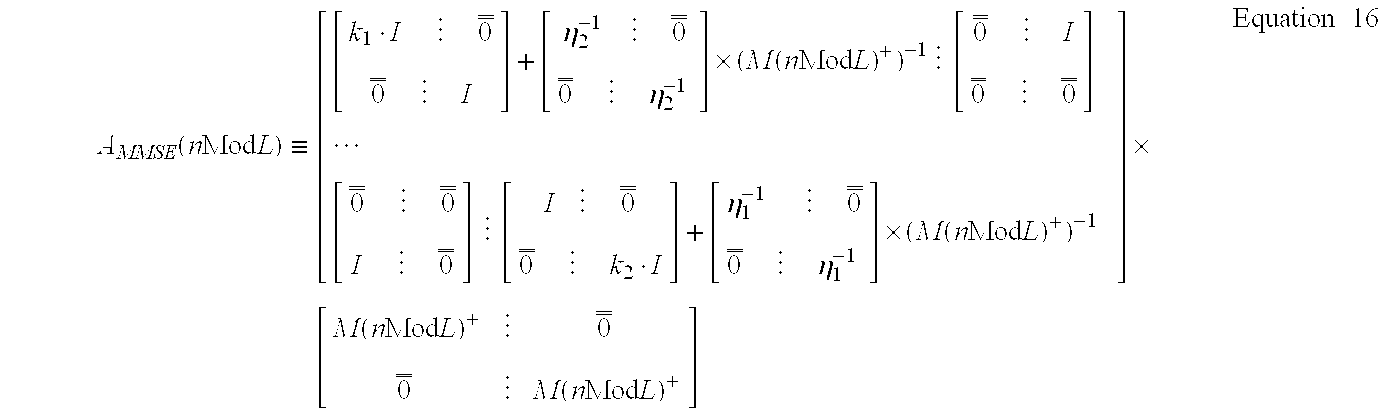
  • Equation 6 Substituting Equation 6 into Equation 7, and differentiating with respect to the ⁇ overscore (C) ⁇ i (n)'s, the following set of normal equations for the proposed receiver front-end are obtained:
  • a MMSE (n Mod L) ⁇ [ [ k 1 ⁇ I ⁇ ⁇ ⁇ 0 _ _ 0 _ _ ⁇ ⁇ I ] + [ ⁇ 2 - 1 ⁇ ⁇ ⁇ 0 _ _ 0 _ _ ⁇ ⁇ ⁇ 2 - 1 ⁇ ] ⁇ ( M ⁇ ( n ⁇ ⁇ Mod ⁇ ⁇ L ) + ) - 1 ⁇ ⁇ ⁇ [ 0 _ _ ⁇ ⁇ I 0 _ _ ⁇ ⁇ 0 _ _ ]
  • ⁇ double overscore (0) ⁇ is a matrix of N_K ⁇ N_K zeros and k i ⁇ E ⁇ ⁇ ⁇ h i ⁇ 4 ⁇ E ⁇ ⁇ ⁇ h 1 ⁇ 2 ⁇ ⁇ E ⁇ ⁇ ⁇ h 2 ⁇ 2 Equation ⁇ ⁇ 17 ⁇ i ⁇ E ⁇ ⁇ ⁇ h i ⁇ 2 ⁇ ⁇ N 2 E ⁇ ⁇ w _ ⁇ ( n ⁇ N ) + ⁇ w _ ⁇ ( n ⁇ N ) ⁇ ⁇ G + ⁇ G Equation ⁇ ⁇ 18
  • the vector w(n.N) denotes N consecutive channel noise samples that are assumed to be i.i.d. (independent and identically distributed), N is the processing gain (or the relationship of chips to symbols) and G is a square diagonal matrix of the gains of individual users and G + ⁇ G is proportional to the users' power levels.
  • ⁇ i is a square diagonal matrix holding the signal to noise ratios (SNRs) of the various users for the i-th finger. If the noise samples are not i.i.d. and/or the noise statistics and/or the user's gain are unknown to the receiver, the SNR matrices ⁇ 1 and ⁇ 2 can be estimated using conventional techniques and then plugged into Equation 16.
  • the matrix M(n Mod L) is the cross-talk matrix (of the PNs) relating the transmitted symbols of the various users to the different despreader outputs. It is defined in Appendix A for both the single and multi-symbol embodiments, but in both cases it is independent of the channel taps or their statistics.
  • the 4K ⁇ 1 vector ⁇ overscore (b) ⁇ MMSE is the vector whose l-th element (related to the user of interest) is +k 1 and whose 2K+K+l-th element is +k 2 . All other elements of ⁇ overscore (b) ⁇ MMSE are zero.
  • the 12K ⁇ 1 vector ⁇ overscore (b) ⁇ MMSE is the vector whose K+l-th element is 1+k 1 and whose 9 ⁇ K+K+l is 1+k 2 . All other elements of ⁇ overscore (b) ⁇ MMSE are zero.
  • the matrix G should be concatenated three times to generate a 3K ⁇ 3K SNR matrix for the “virtual” 3K users (or more if more than three symbols are used at once, i.e. D>1).
  • the MMSE solution of the present invention (represented by Equation 16) is independent of the actual channel estimates ⁇ 1 .
  • the tap weights ⁇ overscore (C) ⁇ MMSE (nmodL) depend on joint moments of the channel estimates (i.e. the statistics of the channel).
  • the channel is time-varying but its statistics are stationary. Since the matrix A MMSE (n Mod L) depends only on the stationary statistics of the channel, its inversion may be performed once, off-line.
  • the tap weights ⁇ overscore (C) ⁇ MMSE (nmodL), which are a function of the matrix A MMSE (n Mod L), may be computed once, typically off-line, for each of the L phases of the PN sequence.
  • the tap weights ⁇ overscore (C) ⁇ MMSE (nmodL) may be subsequently used during operation.
  • Equation 15 and Equation 16 may be implemented on a mobile unit.
  • a decorrelator solution separates the users by removing the cross-correlations between their signatures.
  • the MMSE solution converges to a decorrelator solution in the situation of high SNR ratios (i.e. where there is little additive noise and the dominant interfering term is the cross-talk between the users).
  • the decorrelator solution of the present invention may be found by letting the noise variance approach zero in Equation 16.
  • Equation 16 A ⁇ ( n ⁇ ⁇ Mod ⁇ ⁇ L ) ⁇ ⁇ [ [ k 1 ⁇ I ⁇ 0 _ _ 0 _ _ ⁇ ⁇ I ] ⁇ ⁇ ⁇ ⁇ [ 0 _ _ ⁇ I 0 _ _ ⁇ 0 _ _ ] ⁇ [ 0 _ _ ⁇ 0 _ _ I ⁇ 0 _ _ ] ⁇ ⁇ ⁇ [ I ⁇ 0 _ _ ⁇ 0 _ _ ⁇ k 2 ⁇ I ] ] ⁇ ⁇ [ M ⁇ ( n ⁇ ⁇ Mod ⁇ ) + ⁇ 0 _ _ ⁇ 0 _ _ ⁇ M ⁇ ( n ⁇ ⁇ Mod ⁇ ⁇ L ) + ⁇ ] Equation ⁇ ⁇ 19
  • Equation 19 Equation 19 .
  • C _ DEC ⁇ ( n ⁇ ⁇ Mod ⁇ ⁇ L ) ⁇ [ C _ 1 DEC ⁇ ( n ⁇ ⁇ Mod ⁇ ⁇ L ) C _ 2 DEC ⁇ ( n ⁇ ⁇ Mod ⁇ ⁇ L ) ] ( 4 ⁇ N_K )
  • ⁇ x1 ⁇ [ M ⁇ ( n ⁇ ⁇ Mod ⁇ ⁇ L ) + ⁇ 0 _ _ ⁇ 0 _ _ ⁇ ⁇ M ⁇ ( n ⁇ ⁇ Mod ⁇ L ) + ] ⁇ ⁇ [ e _ ⁇ l e _ K + l + 1 ] Equation ⁇ ⁇ 20
  • ⁇ overscore (e) ⁇ i is the (2 ⁇ N_K) ⁇ 1 normal basis vector whose i-th element is 1, and all other elements are zero.
  • l is set to the desired user number.
  • Equation 20 is generally independent of the channel estimates (and of their statistics). It only depends on the cross-talk matrix M(n Mod L). Thus, as with the MMSE case, the decorrelator solution may be computed once, for all channel conditions.
  • the SNR matrix ⁇ i is a function of the power levels assigned by the base station to each of the mobile user's. Since these power levels may be changed from time to time, the MMSE tap weights should be recomputed whenever the transmission power of any of the users is modified. The following high SNR approximation to the MMSE solution may be utilized to avoid the matrix inversion operation.
  • Equation 16 may be rewritten in the following form: A MMSE ⁇ ( n ⁇ ⁇ Mod ⁇ ⁇ L ) ⁇ ⁇ [ ⁇ + ⁇ ⁇ ( n ⁇ ⁇ Mod ⁇ ⁇ L ) - 1 ] ⁇ ⁇ [ M ⁇ ( n ⁇ ⁇ Mod ⁇ ⁇ L ) + ⁇ 0 _ _ ⁇ 0 _ _ ⁇ ⁇ M ⁇ ( n ⁇ ⁇ Mod ⁇ ⁇ L ) + ] Equation ⁇ ⁇ 21
  • Equation 25 C _ ⁇ MMSE ⁇ ( n ⁇ ⁇ Mod ⁇ ⁇ L ) ⁇ C _ DEC ⁇ ( n ⁇ ⁇ Mod ⁇ ⁇ L ) - [ ⁇ M ⁇ ( n ⁇ ⁇ Mod ⁇ ⁇ L ) + ⁇ 0 _ _ ⁇ 0 _ _ ⁇ ⁇ M ⁇ ( n ⁇ ⁇ Mod ⁇ ⁇ L ) + ] ⁇ ⁇ - 1 ⁇ ⁇ _ ⁇ ( n ⁇ ⁇ Mod ⁇ ⁇ L ) Equation ⁇ ⁇ 28
  • the previous embodiments require off-line matrix inversions.
  • the following adaptive tap weight generators do not require matrix inversions and they typically converge to the solution within finite time.
  • adaptive solutions such as these require initializing the tap weight vectors ⁇ overscore (C) ⁇ adaptive (nmodL) at some simple value, such as all zeros except for the l-th element of C i,i .
  • Equation 7 A least mean squares (LMS) algorithm for minimizing the MSE criterion of Equation 7 is given by iterating over the normal equations in Equation 8. The resulting algorithm is,
  • is the step size parameter
  • t is a cyclic time index given by:
  • NLMS normalized LMS
  • RLS recursive least squares
  • Equation 29 reduces to:
  • ⁇ overscore (C) ⁇ i,j ( t ) ⁇ overscore (C) ⁇ i,j ( t ⁇ 1)+ ⁇ ⁇ overscore (Y) ⁇ i ( n ) ⁇ e ( n;t ⁇ 1) + ⁇ i + 0 ⁇ i,j ⁇ N — F ⁇ 1 Equation 32
  • Equation 31 e(n;t ⁇ 1) is derived by substituting Equation 1 and Equation 2 for r(n) in Equation 31.
  • a drawback of the above algorithms is that the memory size for storing the tap weight vectors is:
  • Equation 32 the error term e(n;t ⁇ 1) of Equation 32 is calculated accordingly.
  • AGC automatic gain control
  • a further embodiment which attempts to reduce the memory requirements, involves initially calculating generally fixed cyclic vectors and, during operation, modifying them with non-cyclic weights ⁇ overscore (d) ⁇ i,j (n).
  • each ⁇ overscore (C) ⁇ i,j (t) is replaced by:
  • R j,i (t) (l) is the l-th row of the cross correlation matrix R j,i (t).
  • R j,i (t) (l) is the cross-talk term from finger j to finger i of the desired (l-th) user.
  • the vector of adaptive weights ⁇ overscore (d) ⁇ i,j (n) is generated by:
  • ⁇ overscore (d) ⁇ i,j ( n ) ⁇ overscore (d) ⁇ i,j ( n ⁇ 1)+ ⁇ Diag ⁇ R j,i ( t ) (l) ⁇ overscore (Y) ⁇ ( n ) ⁇ e ( n;t ) + ⁇ i + 0 ⁇ i,j ⁇ NF ⁇ 1 Equation 36
  • Equation 36 is obtained as described hereinabove but using matrix D for vector C. Note that in the transition to the third line of Equation 37, the fact that R i,i (t) is the identity matrix is used.
  • ⁇ overscore (d) ⁇ i,i (n) may be replaced with ⁇ overscore (e) ⁇ l at the expense of performance degradation.
  • the resulting MUD algorithm output is still given by Equation 36 except that the adaptation is used only for i ⁇ j.
  • Equation 32 and Equation 36 are generally similar. Thus, both may converge to the same MMSE solution. Given this, the two approaches may be combined, where the non-cyclic approach uses less memory while the cyclic approach provides better performance. The combination of the two approaches, allows cost/performance tradeoffs.
  • the present invention may be implemented as a multi-user detector in a computationally-restricted mobile unit.
  • the present invention may also be utilized in base stations which jointly demodulates multiple users.
  • some of the calculations are common to all users.
  • the inverse of the matrix A MMSE is needed for all the users.
  • the separate solution for each user is only a function of the vector ⁇ overscore (b) ⁇ MMSE which has the non-zero elements in the l-th position and l changes for each user.
  • an MMSE, multiple user solution would share the main computational burden of inverting the matrix A MMSE .
  • the despread signal ⁇ overscore (Y) ⁇ (n) is provided to two interference processors 40 and 42 which determine the strongest interfering users to the desired user, user l.
  • the first interference processor 40 determines a pre-processing value K 1 typically by selecting those users with the highest power levels.
  • the second interference processor 42 determines a post-processing value K 2 , for example, by calculating the MSE for the l-th user and selecting the K 2 users which are the strongest contributors to the MSE.
  • the MSE is calculated by resubstitution of the MSE solution of Equation 15 into Equation 6 and then substituting the result into Equation 7.
  • the despread signal ⁇ overscore (Y) ⁇ (n) is also provided to the receiver of the present invention (either of FIG. 1 or FIG. 2 and here labeled 44) which produces multiple “cleaner” signals, one of the desired user e and one of each of the K 2 users.
  • the K 1 users are sources of cross-talk.
  • the K 2 +1 “cleaner” signals are then provided to a conventional MUD 46 for the desired user l.
  • a conventional MMSE receiver processes a small number of strong interfering users after the present invention processes all of the signals.
  • the present invention may be utilized even when there are multiple antennas.
  • the multiple fingers correspond to multipath components of the different antennas, but the present invention simply operates on this larger amount of fingers.
  • the antenna array may be used to null out signals that arrive from base stations that are not handled by the mobile unit or base station which operates the MUD of the present invention. This way, for example, one can use the MUD of the present invention to reduce the interference from other users at the same cell, but use the antenna array to reduce the interference from other cells.
  • the cross-talk matrix (for the single symbol implementation) is defined as: M ⁇ ( n ⁇ ⁇ Mod ⁇ ⁇ L ) ⁇ [ I ⁇ ⁇ ⁇ R 1 , 0 ⁇ ( n ⁇ ⁇ Mod ⁇ ⁇ L ) R 0 , 1 ⁇ ( n ⁇ ⁇ Mod ⁇ ⁇ L ) ⁇ ⁇ ⁇ I ] 2 ⁇ K ⁇ 2 ⁇ K Equation ⁇ ⁇ 39
  • variable ⁇ (t) is the combined transmission and reception filter response sampled at OS times the chip rate: ⁇ ⁇ ( t ) ⁇ ⁇ - ⁇ ⁇ ⁇ h Tx ⁇ ( t ⁇ T c / OS - ⁇ ) ⁇ h Rx ⁇ ( ⁇ ) ⁇ ⁇ ⁇ ⁇ Equation ⁇ ⁇ 41
  • h Tx and h Rx are the transmission and reception filter responses, respectively and T c is the chip period.
  • ⁇ k,i ⁇ (d k ⁇ d i )/OS ⁇ and d k is the delay (in samples) associated with the k-th multipath component, i.e. ⁇ k,i is the delay difference between the k-th and i-th fingers in multiples of chips.
  • ⁇ k,i is the fractional delay between these fingers and is thus given by, d k ⁇ d i ⁇ k,i ⁇ OS.
  • the cross correlation matrices are given by: Rp ⁇ ( d , n ) ⁇ 1 N ⁇ P ⁇ ( n ⁇ N ) + ⁇ ( I ⁇ ( N ) - I ⁇ ( d ) ) ⁇ P ⁇ ( n ⁇ N - d ) Equation ⁇ ⁇ 43 Rn ⁇ ( d , n ) ⁇ 1 N ⁇ P ⁇ ( n ⁇ N ) + ⁇ I ⁇ ( d ) ⁇ P ⁇ ( n ⁇ N - d ) Equation ⁇ ⁇ 44
  • PN i (k) is the combined PN sequence and Walsh/Hadamard code for the i-th user.
  • the matrix I(d) is an N ⁇ N diagonal matrix whose first d elements on the main diagonal are unity and all other elements are zero (thus, I(N) is simply the identity matrix).
  • the cross-talk matrix M is given by: M ⁇ ( n ⁇ ⁇ Mod ⁇ ⁇ L ) ⁇ [ I ⁇ 0 _ _ ⁇ ⁇ 0 _ _ ⁇ ⁇ Rp 1 , 0 ⁇ ( n + 1 ) ⁇ Rn 1 , 0 ⁇ ( n + 1 ) ⁇ 0 _ _ ⁇ 0 _ _ ⁇ ⁇ I ⁇ 0 _ _ ⁇ ⁇ 0 _ _ ⁇ ⁇ Rp 1 , 0 ⁇ ( n ) ⁇ Rn 1 , 0 ⁇ ( n ) 0 _ _ ⁇ ⁇ 0 _ _ ⁇ ⁇ I ⁇ 0 _ _ ⁇ ⁇ 0 _ _ ⁇ ⁇ I ⁇ 0 _ _ ⁇ ⁇ 0 _ _ ⁇ ⁇ I ⁇ 0 _ _ ⁇ ⁇ 0 _ _ ⁇ ⁇ Rp 1

Abstract

A multi-user detector of transmitted signals includes a bank of despreaders and a processor. Each despread signal (produced by the despreaders) has cyclic and channel variations. The bank of despreaders despreads the transmitted signals to produce despreaded signals and the processor receives the despreaded signals and separately processes the cyclic and the channel variations. The processor includes a cyclic variation processor and a channel variation processor. The cyclic variation processor generally processes the cyclic variation of the transmitted signals and the channel variation processor communicates with the cyclic variation processor and processes at least the channel variation of the transmitted signals. The cyclic variation processor includes a weighting operator which weights the transmitted signals with at least one tap weight and a tap weight generator which generates the at least one tap weight at least from a cyclic code.

Description

BACKGROUND OF THE PRESENT INVENTION
In code division, multiple access (CDMA) cellular telephony, a mobile telephone communicates with a base station where each user and each base station has its own “spreading code” used for modulation of the transmitted signal and for separating the different signals corresponding to different users/subscribers. Typically, a receiver picks up many echoes (multipath reflections) of a transmitted signal, each having different and randomly varying delays and amplitudes. In such a scenario, the spreading codes that were originally designed to be orthogonal among the different users are no longer orthogonal and the users are no longer separated. Consequently, a mobile unit, when attempting to detect only a single user, regards all other channel users (including signals from other base stations) as creators of interference. One exemplary single-user multipath detector is a rake receiver that combines the different channel paths into a single replica of the transmitted signal.
The rake receiver detects the signal of interest while treating the interference from other users as background noise. A multiple-user detection (MUD) scheme, on the other hand, incorporates various levels of a-priori information on the interference and may significantly outperform the rake receiver (or any other single-user receiver). The maximal level of a-priori information occurs when the interfering signal is completely known to the receiver, as is the case in U.S. Pat. No. 6,034,986. In the past two decades, numerous methods for multi-user detection were developed based on different levels of utilization of a-priori information and leading to different levels of receiver complexity.
Unfortunately, multi-user detection schemes are significantly more complex than single-user ones. Not only does multi-user detection require (either explicitly or implicitly) processing the received signal with a bank of despreaders (with each despreader being matched to a distinct user), the outputs of this despreader bank must further be processed according to some a priori criterion, such as the maximum likelihood criterion, whose complexity is exponential in the number of users.
Exponential complexity is intolerable unless the number of users is extremely small, which is not the case in cellular communications. Therefore, suboptimal, linear MUD schemes were developed, among them are the decorrelator and/or the minimum mean squared error (MMSE) receiver. Still, linear MUDs require that a signature cross-correlation matrix, or a rescaled version of which, be inverted with each new symbol/block that arrives. This is computationally too heavy to be performed by the mobile unit. Numerous methods for approximating matrix inversion were suggested recently, such as Verdu's first order approximation (O(K) operations per symbol per user).
Another weakness of existing MUD schemes for long code DS-CDMA (where the spreading code spans more than one symbol) is that there is no simple approach to turn them into the more desirable form of adaptive algorithms, since a symbol rate adaptive algorithm cannot track the symbol rate variations of the cross-correlation matrix. In fact, the problem of adaptive algorithms for long code DS-CDMA is regarded an open problem in the scientific literature.
U.S. Patent Publication WO 00/18030, assigned to the common assignee of the present invention, recognizes that the spreading codes are cyclic and describes a method of processing received signals by dividing the cyclic spreading codes into a plurality of sections. Each section is assigned a different cost function and a respective set of receiver parameters that are used to minimize the associated cost function. Portions of the received signal which were spread by the same section of code are jointly processed, so as to dynamically update the associated set of receiver parameters.
BRIEF DESCRIPTION OF THE DRAWINGS
The subject matter regarded as the invention is particularly pointed out and distinctly claimed in the concluding portion of the specification. The invention, however, both as to organization and method of operation, together with objects, features, and advantages thereof, may best be understood by reference to the following detailed description when read with the accompanying drawings in which:
FIG. 1 is a schematic illustration of an embodiment of a multi-user detector (MUD) in accordance with a first embodiment the present invention;
FIG. 2 is a schematic illustration of an embodiment of a MUD in accordance with a second, multi-symbol embodiment the present invention; and
FIG. 3 is a schematic illustration of a two-step MUD using the present invention and a conventional MUD.
It will be appreciated that, for simplicity and clarity of illustration, elements shown in the figures have not necessarily been drawn to scale. For example, the dimensions of some of the elements may be exaggerated relative to other elements for clarity. Further, where considered appropriate, reference numerals may be repeated among the figures to indicate corresponding or analogous elements.
DETAILED DESCRIPTION OF PREFERRED EMBODIMENTS
In the following detailed description, numerous specific details are set forth in order to provide a thorough understanding of the invention. However, it will be understood by those skilled in the art that the present invention may be practiced without these specific details. In other instances, well-known methods, procedures, components and circuits have not been described in detail so as not to obscure the present invention.
Some portions of the detailed description which follow are presented in terms of algorithms and symbolic representations of operations on data bits or binary digital signals within a computer memory. These algorithmic descriptions and representations may be the techniques used by those skilled in the data processing arts to convey the substance of their work to others skilled in the art.
An algorithm is here, and generally, considered to be a self-consistent sequence of acts or operations leading to a desired result. These include physical manipulations of physical quantities. Usually, though not necessarily, these quantities take the form of electrical or magnetic signals capable of being stored, transferred, combined, compared, and otherwise manipulated. It has proven convenient at times, principally for reasons of common usage, to refer to these signals as bits, values, elements, symbols, characters, terms, numbers or the like. It should be understood, however, that all of these and similar terms are to be associated with the appropriate physical quantities and are merely convenient labels applied to these quantities.
Unless specifically stated otherwise, as apparent from the following discussions, it is appreciated that throughout the specification discussions utilizing terms such as “processing,” “computing,” “calculating,” “determining,” or the like, refer to the action and/or processes of a computer or computing system, or similar electronic computing device, that manipulate and/or transform data represented as physical, such as electronic, quantities within the computing system's registers and/or memories into other data similarly represented as physical quantities within the computing system's memories, registers or other such information storage, transmission or display devices.
Embodiments of the present invention may include apparatuses for performing the operations herein. This apparatus may be specially constructed for the desired purposes, or it may comprise a general purpose computer selectively activated or reconfigured by a computer program stored in the computer. Such a computer program may be stored in a computer readable storage medium, such as, but is not limited to, any type of disk including floppy disks, optical disks, CD-ROMs, magnetic-optical disks, read-only memories (ROMs), random access memories (RAMs), electrically programmable read-only memories (EPROMs), electrically erasable and programmable read only memories (EEPROMs), magnetic or optical cards, or any other type of media suitable for storing electronic instructions, and capable of being coupled to a computer system bus.
A conventional spread spectrum signal may be viewed as the result of mixing a narrowband information-bearing signal s[n] with an informationless wideband “spreading” signal PN[n], where the spreading signal is a pseudo-noise (PN) sequence. The receiver synchronizes the incoming signal to a locally generated version PN0[n] of PN[n] and mixes the received signal with the locally generated PN sequence PN0[n], thereby removing the original PN sequence PN[n] from the signal and “collapsing” the signal to the information-bearing signal s[n].
The spreading signal PN[n] is typically a coding sequence of some kind, such as a pseudo-random code. For example, the IS-95 standard for cellular communication employs the product of a 64 chip Walsh code (aimed at separating up to 64 different users per base) and a periodic PN sequence (aimed at separating the different bases) which is typically a “long code” of 512*64 chips (or 512 symbols). The spreading signal for each user is its Walsh code combined with the current 64 chips of the PN sequence of its base station. The PN code is finite and thus, is used cyclically.
The present invention comprises a family of linear, multi-user detectors that jointly process portions of the received signals which were spread by the same section of the cyclic spreading code, or by adjacent sections of code (e.g. for the codes which spread neighboring symbols n−1, n, n+1). As described in detail hereinbelow, the receiver structure of the present invention decouples the processing of the cyclic variation (from the PN sequence) from the channel variation (due to the transmission of the signal). Thus, for example, the present invention generally avoids the need for real-time matrix inversions due to channel and PN variations, such as is required with the conventional approach.
With the proposed approach, the PN dependent term holding the users' signature cross-correlation matrix is generally independent of the instantaneous channel conditions (it does depend on long time averaging properties of the channel), and therefore, the relevant matrix inversions may be calculated a-priori (or off-line). The present invention also comprises a family of adaptive MUD algorithms for long code DS-CDMA.
Reference is now made to FIG. 1, which illustrates a first embodiment of the detector of the present invention, operative on N_F fingers. It is noted that fingers j represent different transmission paths for the same signal and thus, are delayed from each other.
The detector of FIG. 1 comprises N_F despreader banks 10, N_F cyclic variation processors 12, one per finger, a single channel variation processor 14, a tap weight generator 16 and a channel estimator 18.
Both types of processors 12 and 14 have a rake-type shape in that each input signal to the processor, one per finger, is multiplied in some fashion with a calculated value associated with that finger and the resultant signals are summed together.
The jth despreader bank 10 operates to despread the digitized antenna signals, after downconversion and filtering, producing the despreader output vector {overscore (Y)}j(n) for the jth finger. In general, {overscore (Y)}j(n) is a vector of K elements, the l-th one of which corresponds to the despreaded version of the user of interest and the other K−1 are despreaded versions of some other users. These K−1 additional users are despreaded and are used in processing the signal of the l-th user in order to improve the detection of the transmitted signal of the desired user. Each despreader within the bank 10 has the spreading code associated with the ith user (1≦i≦K) and produces that user's estimated signal for each symbol n.
Each cyclic variation processor 12 comprises a plurality of vector multipliers 20 and a first level summer 22 while channel variation processor 14 comprises a plurality of scalar multipliers 24 and a second level summer 26. It is noted that vector multipliers 20 produce the inner product < x _ , y _ > i x _ i · y _ i
Figure US06618433-20030909-M00001
between the vectors {overscore (X)} and {overscore (Y)}.
In each cyclic variation processor 12, each vector multiplier 20 produces the inner product between the despreader output vector {overscore (Y)}j(n) of the jth finger and a per-processor, per-finger tap weight vector Ci,j(n mod L) where the tap weights are cyclical and the cycle is of length L, the length of the PN sequence in symbols. The tap weights are produced by tap weight generator 16 from a despreader output vector {overscore (Y)}(n) as discussed in more detail hereinbelow. First level summer 22 sums the output of the vector multipliers 20, to produce the signal zi(n) for the ith finger. Mathematically, this is given by: z i ( n ) = j = 1 N_F C _ i , j ( n mod L ) + · Y _ j ( n ) Equation 1
Figure US06618433-20030909-M00002
where + denotes the conjugate transpose operator The channel variation processor 14 operates as follows: The ith multiplier 24 multiplies the ith signal zi(n) with the ith channel tap estimate ĥi (from channel estimator 18). Second level summer 26 sums the outputs of the multipliers 24, thereby to produce the user output signal r(n). Mathematically, this is given by: r ( n ) i = 1 N_F h ^ i + · z i ( n ) Equation 2
Figure US06618433-20030909-M00003
It will be appreciated that the tap weights {overscore (C)}i,j(n mod L) are generated to emphasize the l-th user from among the multiplicity of users such that user output signal r(n) has minimal noise and cross-talk from the other K−1 users. To do so, tap weight generator 16 attempts to optimize some performance criterion defined with respect to user output r(n), as discussed in more detail hereinbelow.
The issue of how to choose those other K−1 users will not be addressed, since it is known in the art, except to note that one generally chooses those users that are strongly interfering with the desired user. It is further noted that channel estimator 18 is a conventional channel estimator and therefore, it will not be discussed in more detail except to note that it provides the estimated channel coefficients to tap weight generator 16.
The signal r(n) is then passed on for further processing to a symbol detector (not shown) or to a de-interleaver and then to a decoder (neither shown) in the case of coded communications, as is known in the art.
It should also be noted that Equation 2 corresponds to what is known as a maximal ratio combining, but other combining criteria may be utilized, e.g. a selection criterion that sets r(n) to be equal to the element in the sum of Equation 2 whose amplitude is maximal. The computational complexity is significantly reduced in this case, since only one cyclic variation processor 12 needs to be active.
Note also that the conventional rake receiver is obtained as a special case of the above, in which all elements of the {overscore (C)}i,i(nmodL)s are set to zero except the l-th element of {overscore (C)}i,i(nmodL), for all 1≦i≦N_F, which is set to unity. The value of l is the desired user number. In this case, the output of the other K−1 users is completely ignored.
As opposed to conventional practice which often uses the multi-user rake outputs as the MUD input, the present invention operates directly on the despreader outputs. From the despreader outputs one may generate the bank of rake receiver outputs. However, the set of despreader outputs is much more redundant (by a factor of N_F2) than the bank of rake outputs. This would imply that the present invention requires a larger dimensionality than the conventional approach. Nevertheless, as discussed hereinbelow, there are advantages to this more redundant approach.
The present invention also incorporates a multiple-symbol MUD detector, shown in FIG. 2 to which reference is now made. This detector comprises N_F, multi-symbol despreader banks 30, a concatenator 32, N_F vector multipliers 34, one per finger, N_F multipliers 36, a summer 38, tap weight generator 16 and channel estimator 18.
As before, each despreader bank 30 operates to despread the digitized antenna signals, after downconversion and filtering, for one finger. However, in this embodiment, each despreader bank 30 produces multiple symbols at a time, around a center symbol n. The jth despreader output is now, Y _ _ j ( n ) = [ Y _ j ( n + D ) Y _ j ( n + D - 1 ) Y _ j ( n + 1 ) Y _ j ( n ) Y _ j ( n - 1 ) Y _ j ( n - D + 1 ) Y _ j ( n - D ) ] Equation 3
Figure US06618433-20030909-M00004
where D is a design parameter. For example, D may be set to 1. For the purpose of simplifying notation, the concatenated vector of all despreader bank output is still denoted by {overscore (Y)}(n) as with the previous case.
Concatenator 32 concatenates the outputs of multi-symbol despreader banks 30 to produce the despreader output vector {overscore (Y)}(n) which is provided as input to each vector multiplier 34. The latter produce the inner product of the despreader output vector and a per-finger tap weight vector {overscore (C)}i(nModL). The relevant multiplier 36 multiplies the output of each vector multiplier 34 by its associated channel estimate ĥi and summer 38 combines the results into the user signal r(n). As in the previous embodiment, the tap weights {overscore (C)}i(nModL) are generated to emphasize one user from among the multiplicity of users such that user output signal r(n) has minimal noise and cross-talk from the other users.
It is further noted that {overscore (C)}i(nModL) is a concatenation of the tap weights of the previous embodiment as follows:
{overscore (C)} i(nModL)=[{overscore (C)} i,0(nModL)T ,{overscore (C)} i,1(nModL)T , . . . , {overscore (C)} i,N F−1(nModL)T]T  Equation 4
The output signal r(n) is given by: r ( n ) i = 0 N_F - 1 C _ i ( n Mod L ) + · ( h ^ i + · Y _ ( n ) ) = ( i = 0 N_F - 1 C _ i ( n Mod L ) + · h ^ i + ) · Y _ ( n ) Equation 5
Figure US06618433-20030909-M00005
The next section of the present application discusses a number of different tap weight generators 16. The following section discusses a number of different uses of the present invention. The claims follow Appendix A which details how to generate one element used in the following discussion.
The Tap Weight Generator
The MMSE Tap Weight Generator
With the above MUD front-end, we now consider the well known minimum mean square error (MMSE) performance criterion. Let, e ( n ) s l ( n ) · j = 0 N_F - 1 h ^ j 2 - r ( n ) = s l ( n ) · j = 0 N_F - 1 h ^ j 2 - j = 0 N_F - 1 C _ j ( n Mod L ) + · h ^ j + · Y _ ( n ) Equation 6
Figure US06618433-20030909-M00006
where sl(n) is the transmitted signal of the user of interest and the term Σ|ĥj|2 is used only for the purpose of gain normalization. Then, the MMSE criterion is aimed at minimizing:
MSE=E{|e(n)|2  Equation 7
where E{· stands for the expectation operator taken with respect to the transmitted symbols, the channel noise, and the channel taps. Note that conventional practice is to take the channel taps as deterministic and known quantities, and thus exclude them from the expectation operation. The present invention, on the other hand, includes the channel taps, hence the MMSE solution may be interpreted as the one that minimizes the mean square error (MSE) over the ensemble of channels.
Substituting Equation 6 into Equation 7, and differentiating with respect to the {overscore (C)}i(n)'s, the following set of normal equations for the proposed receiver front-end are obtained:
E{{overscore (Y)}(nĥ i ·e(n)+}=0 i=0,1, . . . , NF− 51  Equation 8
Re-substitution of Equation 6, yields j = 0 N_F - 1 E { Y _ ( n ) · h ^ i + · h ^ j · Y _ ( n ) + } · C _ j ( n Mod L ) = E { Y _ ( n ) · h ^ i + · j = 0 N_F - 1 h ^ j 2 · s l ( n ) + } i = 0 , 1 , , N_F - 1 Equation 9
Figure US06618433-20030909-M00007
The above set of normal equations depend on the joint probability distribution of the channel taps (and their estimators). The following assumptions may be made:
Assumption 1:
Perfect channel knowledge, i.e.
ĥ i =h i i   Equation 10
and the following very mild assumptions on the joint distribution of the channel taps
Assumption 2:
E{h i}=0∀i  Equation 11
Assumption 3:
E{|h i|2 },E{|h i|4 }<∞∀i   Equation 12
Assumption 4:
E{h i a·(h i +)b ·h j c·(h j +)d }=E{h i a·(h i +)b }·E{h j c·(h j +)d } ∀i≠j, 0≦a,b,c,d<4  Equation 13
Assumption 5:
E{|h i|2 ·h i +}=0 i   Equation 14
It is noted that the above assumptions may be satisfied for many commonly used multi-path channel models, e.g. the conventional practice in cellular channels which is Rayleigh fading with independent multipath components. However, one may derive the MMSE solution with any given (and finite) joint moments of the channel taps generally up to the fourth order. In practice, one may use the channel estimator to measure these moments and solve accordingly without introducing any a-priori assumptions regarding the joint probability distribution of the channel taps. It should also be noted that simulation results revealed a low sensitivity of the overall performance to the above set of assumptions.
After carrying out the necessary expectation operations, Equation 9 may be written as: C _ MMSE ( n Mod L ) = [ C _ 0 MMSE ( n Mod L ) C _ N - F - 1 MMSE ( n Mod L ) ] ( N_F 2 · N_K ) x1 = A MMSE ( n Mod L ) - 1 · b _ MMSE Equation 15
Figure US06618433-20030909-M00008
where, for the single symbol model of FIG. 1, N_K=K and for the multi-symbol model of FIG. 2, N_K=3K or larger if more symbols are used at once (i.e. D>1). For 2 fingers (i.e. N_F=2), the matrix, AMMSE(n Mod L), is given by: A MMSE ( n Mod L ) [ [ k 1 · I 0 _ _ 0 _ _ I ] + [ η 2 - 1 0 _ _ 0 _ _ η 2 - 1 ] × ( M ( n Mod L ) + ) - 1 [ 0 _ _ I 0 _ _ 0 _ _ ] [ 0 _ _ 0 _ _ I 0 _ _ ] [ I 0 _ _ 0 _ _ k 2 · I ] + [ η 1 - 1 0 _ _ 0 _ _ η 1 - 1 ] × ( M ( n Mod L ) + ) - 1 ] × [ M ( n Mod L ) + 0 _ _ 0 _ _ M ( n Mod L ) + ] Equation 16
Figure US06618433-20030909-M00009
where {double overscore (0)} is a matrix of N_K×N_K zeros and k i E { h i 4 } E { h 1 2 } · E { h 2 2 Equation 17
Figure US06618433-20030909-M00010
η i E { h i 2 } · N 2 E { w _ ( n · N ) + · w _ ( n · N ) } · G + · G Equation 18
Figure US06618433-20030909-M00011
where, the vector w(n.N) denotes N consecutive channel noise samples that are assumed to be i.i.d. (independent and identically distributed), N is the processing gain (or the relationship of chips to symbols) and G is a square diagonal matrix of the gains of individual users and G+·G is proportional to the users' power levels. It will be appreciated that ηi is a square diagonal matrix holding the signal to noise ratios (SNRs) of the various users for the i-th finger. If the noise samples are not i.i.d. and/or the noise statistics and/or the user's gain are unknown to the receiver, the SNR matrices η1 and η2 can be estimated using conventional techniques and then plugged into Equation 16.
The matrix M(n Mod L) is the cross-talk matrix (of the PNs) relating the transmitted symbols of the various users to the different despreader outputs. It is defined in Appendix A for both the single and multi-symbol embodiments, but in both cases it is independent of the channel taps or their statistics.
For the single symbol model of FIG. 1, with N_F=2, the 4K×1 vector {overscore (b)}MMSE is the vector whose l-th element (related to the user of interest) is +k1 and whose 2K+K+l-th element is +k2. All other elements of {overscore (b)}MMSE are zero.
For the multi-symbol model of FIG. 2, the 12K×1 vector {overscore (b)}MMSE is the vector whose K+l-th element is 1+k1 and whose 9·K+K+l is 1+k2. All other elements of {overscore (b)}MMSE are zero. In this embodiment, the matrix G should be concatenated three times to generate a 3K×3K SNR matrix for the “virtual” 3K users (or more if more than three symbols are used at once, i.e. D>1).
It will be appreciated that the MMSE solution of the present invention (represented by Equation 16) is independent of the actual channel estimates ĥ1. Instead, the tap weights {overscore (C)}MMSE(nmodL) depend on joint moments of the channel estimates (i.e. the statistics of the channel). In many cases, the channel is time-varying but its statistics are stationary. Since the matrix AMMSE (n Mod L) depends only on the stationary statistics of the channel, its inversion may be performed once, off-line.
Thus, the tap weights {overscore (C)}MMSE(nmodL), which are a function of the matrix AMMSE(n Mod L), may be computed once, typically off-line, for each of the L phases of the PN sequence. The tap weights {overscore (C)}MMSE(nmodL) may be subsequently used during operation.
It will be appreciated that, since the matrix inversion of Equation 15 and Equation 16 occurs once and thus, the L values of {overscore (C)}MMSE(nmodL) are fixed, the present invention may be implemented on a mobile unit.
The Decorrelator Tap Weight Generator
A decorrelator solution separates the users by removing the cross-correlations between their signatures. Typically, the MMSE solution converges to a decorrelator solution in the situation of high SNR ratios (i.e. where there is little additive noise and the dominant interfering term is the cross-talk between the users). The decorrelator solution of the present invention may be found by letting the noise variance approach zero in Equation 16. In this situation, the SNR matrix ηi converges to infinity and thus, the matrix in Equation 16 converges to: A ( n Mod L ) [ [ k 1 · I 0 _ _ 0 _ _ I ] [ 0 _ _ I 0 _ _ 0 _ _ ] [ 0 _ _ 0 _ _ I 0 _ _ ] [ I 0 _ _ 0 _ _ k 2 · I ] ] × [ M ( n Mod L ) + 0 _ _ 0 _ _ M ( n Mod L ) + ] Equation 19
Figure US06618433-20030909-M00012
Substituting Equation 19 into Equation 15 produces the decorrelator solution, where, for simplicity we present the solution for N_F=2: C _ DEC ( n Mod L ) = [ C _ 1 DEC ( n Mod L ) C _ 2 DEC ( n Mod L ) ] ( 4 · N_K ) x1 = [ M ( n Mod L ) + 0 _ _ 0 _ _ M ( n Mod L ) + ] × [ e _ l e _ K + l + 1 ] Equation 20
Figure US06618433-20030909-M00013
where {overscore (e)}i is the (2·N_K)×1 normal basis vector whose i-th element is 1, and all other elements are zero. As before, l is set to the desired user number.
It will be appreciated that the solution in Equation 20 is generally independent of the channel estimates (and of their statistics). It only depends on the cross-talk matrix M(n Mod L). Thus, as with the MMSE case, the decorrelator solution may be computed once, for all channel conditions.
Approximate MMSE Tap Weight Generators
Through the matrix G, the SNR matrix ηi is a function of the power levels assigned by the base station to each of the mobile user's. Since these power levels may be changed from time to time, the MMSE tap weights should be recomputed whenever the transmission power of any of the users is modified. The following high SNR approximation to the MMSE solution may be utilized to avoid the matrix inversion operation.
Equation 16 may be rewritten in the following form: A MMSE ( n Mod L ) [ α + β ( n Mod L ) - 1 ] × [ M ( n Mod L ) + 0 _ _ 0 _ _ M ( n Mod L ) + ] Equation 21
Figure US06618433-20030909-M00014
where α [ [ k 1 · I 0 _ _ 0 _ _ I ] [ 0 _ _ I 0 _ _ 0 _ _ ] [ 0 _ _ 0 _ _ I 0 _ _ ] [ I 0 _ _ 0 _ _ k 2 · I ] ] Equation 22
Figure US06618433-20030909-M00015
and β ( n Mod L ) [ M ( n Mod L ) + × [ η 2 0 _ _ 0 _ _ η 2 ] [ 0 _ _ 0 _ _ 0 _ _ 0 _ _ ] [ 0 _ _ 0 _ _ 0 _ _ 0 _ _ ] M ( n Mod L ) + × [ η 1 0 _ _ 0 _ _ η 1 ] ] Equation 23
Figure US06618433-20030909-M00016
Now, applying a simple high SNR first order approximation, the following is obtained:
[α+β(n Mod L)−1]−1≈α−1β(n Mod L)−1×α−2  Equation 24
Substituting this into Equation 15, the following high-SNR approximation for the MMSE solution is obtained: C _ MMSE ( n Mod L ) [ M ( n Mod L ) + 0 _ _ 0 _ _ M ( n Mod L ) + ] - 1 × α - 1 × b _ MMSE - [ M ( n Mod L ) + 0 _ _ 0 _ _ M ( n Mod L ) + ] - 1 × β ( n Mod L ) - 1 × α - 2 × b _ MMSE C _ DEC ( n Mod L ) - [ M ( n Mod L ) + 0 _ _ 0 _ _ M ( n Mod L ) + ] - 1 × β ( n Mod L ) - 1 × α - 2 × b _ MMSE C _ DEC ( n Mod L ) - η - 1 × Δ _ ( n Mod L ) Equation 25
Figure US06618433-20030909-M00017
where, in the transition to the last line of Equation 25, the simple approximation M(n)−1≈I is utilized and where: η [ [ η 2 0 _ _ 0 _ _ η 2 ] [ 0 _ _ 0 _ _ 0 _ _ 0 _ _ ] [ 0 _ _ 0 _ _ 0 _ _ 0 _ _ ] [ η 1 0 _ _ 0 _ _ η 1 ] ] Equation 26
Figure US06618433-20030909-M00018
and Δ _ ( n Mod L ) [ M ( n Mod L ) + 0 _ _ 0 _ _ M ( n Mod L ) + ] - 1 × α - 2 × b _ MMSE Equation 27
Figure US06618433-20030909-M00019
It will be appreciated that this approximate MMSE solution is relatively simple to implement. The vectors of the decorrelator MUD as well as {overscore (Δ)}(n Mod L) are computed once. From that point on, generally all variations of the power and channel noise variance of the users are taken into account via the SNR matrix η. No extra computational effort (i.e. MIPS) is required aside from that necessary to perform the updates {overscore (C)}DEC(n Mod L)−η−1×{overscore (Δ)}(n Mod L), which are simple due to the fact that η is diagonal.
It is noted that, from Equation 25, it also follows that: C _ MMSE ( n Mod L ) C _ DEC ( n Mod L ) - [ M ( n Mod L ) + 0 _ _ 0 _ _ M ( n Mod L ) + ] η - 1 × Δ _ ( n Mod L ) Equation 28
Figure US06618433-20030909-M00020
which is another approximate solution which can be utilized when the user's power is varying.
Adaptive Tap Weight Generators
The previous embodiments require off-line matrix inversions. The following adaptive tap weight generators do not require matrix inversions and they typically converge to the solution within finite time. Typically, adaptive solutions such as these require initializing the tap weight vectors {overscore (C)}adaptive(nmodL) at some simple value, such as all zeros except for the l-th element of Ci,i.
A least mean squares (LMS) algorithm for minimizing the MSE criterion of Equation 7 is given by iterating over the normal equations in Equation 8. The resulting algorithm is,
{overscore (C)} i(t)={overscore (C)} i(t−1)+μ·{overscore (Y)}(ne(n;t−1)+ ·ĥ i +0≦i≦N F−1  Equation 29
where μ is the step size parameter, t is a cyclic time index given by:
t=(n Modulo L)t−1=((n−L)Modulo L)  Equation 30
and the error term e(n;t−1) is given by: e ( n ; t - 1 ) s l ( n ) · j = 0 N_F - 1 h ^ j 2 - r ( n ; t - 1 ) = s l ( n ) · j = 0 N_F - 1 h ^ j 2 - j = 0 N_F - 1 C _ j ( t - 1 ) + · h ^ j + · Y _ ( n ) Equation 31
Figure US06618433-20030909-M00021
It will be appreciated that the present invention incorporates other adaptive algorithms, e.g. the normalized LMS (NLMS) or the recursive least squares (RLS) and its variants, which may be derived similarly.
For the front-end of in FIG. 1, Equation 29 reduces to:
{overscore (C)} i,j(t)={overscore (C)} i,j(t−1)+μ·{overscore (Y)} i(ne(n;t−1)+ ·ĥ i +0≦i,j≦N F−1  Equation 32
where e(n;t−1) is derived by substituting Equation 1 and Equation 2 for r(n) in Equation 31.
A drawback of the above algorithms is that the memory size for storing the tap weight vectors is:
L·Dim{{overscore (C)}i,j }·N F 2  Equation 33
In order to reduce this memory requirement (but at the expense of performance), one can replace {overscore (C)}i,i(t) by the basis vector {overscore (e)}l. The resulting algorithm is still given by Equation 32 except that, in this embodiment, only the terms with i≠j are taken. The MUD output is in this case given by: r ( n ; t - 1 ) i = 1 N_F h ^ i + [ e _ l + · Y _ i ( n ) + j = 1 , j i N_F C _ i , j ( t - 1 ) + · Y _ j ( n ) ] Equation 34
Figure US06618433-20030909-M00022
and the error term e(n;t−1) of Equation 32 is calculated accordingly. One can also replace {overscore (C)}i,i(t) by {overscore (e)}l·gi,i(n) with the scalar gi,i(n) adapted similarly and acting as an automatic gain control (AGC) per finger.
Cyclic and Non-Cyclic Approaches
A further embodiment, which attempts to reduce the memory requirements, involves initially calculating generally fixed cyclic vectors and, during operation, modifying them with non-cyclic weights {overscore (d)}i,j(n). For the structure of FIG. 1, each {overscore (C)}i,j(t) is replaced by:
{overscore (D)} i,j(t,n)≡≡Diag{R j,i(t)(l) }·{overscore (d)} i,j(n)  Equation 35
where Rj,i(t)(l) is the l-th row of the cross correlation matrix Rj,i(t). Thus, Rj,i(t)(l) is the cross-talk term from finger j to finger i of the desired (l-th) user. In this embodiment, the cyclic time t=n Mod L is used for the cross-correlation matrix R, but the conventional symbol timing (i.e. non-cyclic) is used for the vector of adaptive weights {overscore (d)}i,j(n). It will be appreciated that there is a single vector {overscore (d)}i,j(n) for all L phases. Thus, in terms of storage, we completely eliminate the multiplication by L in Equation 33.
The vector of adaptive weights {overscore (d)}i,j(n) is generated by:
{overscore (d)} i,j(n)={overscore (d)}i,j(n−1)+μ·Diag{R j,i(t)(l) }·{overscore (Y)}(ne(n;t)+ ·ĥ i +0≦i,j≦NF−1  Equation 36
It will be appreciated that a non-cyclic adaptation is performed; thus the recursion is over the time index n rather than the cyclic time index t.
The MUD output is given by: r ( n ; t ) i = 1 N_F h ^ i + [ D _ i , i ( t , n - 1 ) + · Y _ i ( n ) + j = 1 , j i N_F D _ i , j ( t , n - 1 ) + · Y _ j ( n ) ] = i = 1 N_F h ^ i + [ d i , i ( n - 1 ) + · Y _ i ( n ) + j = 1 , j i N_F d i , j ( n - 1 ) + · Diag { R j , i ( t ) l } + · Y _ j ( n ) ] Equation 37
Figure US06618433-20030909-M00023
and the error term of Equation 36 is obtained as described hereinabove but using matrix D for vector C. Note that in the transition to the third line of Equation 37, the fact that Ri,i(t) is the identity matrix is used.
As in previous embodiments, {overscore (d)}i,i(n) may be replaced with {overscore (e)}l at the expense of performance degradation. The resulting MUD algorithm output is still given by Equation 36 except that the adaptation is used only for i≠j. The MUD output is given by, r ( n ; t ) i = 1 N_F h ^ i + [ e _ l + · Y _ i ( n ) + j = 1 , j i N_F D _ i , j ( t , n - 1 ) + · Y _ j ( n ) ] = i = 1 N_F h ^ i + [ e _ l + Y _ i ( n ) + j = 1 , j i N_F d i , j ( n - 1 ) + Diag { R j , i ( t ) ( l ) } + Y _ j ( n ) ] Equation 38
Figure US06618433-20030909-M00024
It will be appreciated that the present invention may also be developed using other types of least squares calculations, such as recursive least squares (RLS) and normalized least mean squares.
Cyclic and Non-Cyclic Approaches
It can be shown that, when the weights {overscore (d)}i,j(n) are allowed to be cyclic and with the choice of:
{overscore (d)} i,i(t)={overscore (C)} i,i(t) and {overscore (d)} i,j(t)=Diag{R j,i(t)(l)}−1 ·{overscore (C)} i,j(t)
the outputs of the MUD algorithms of Equation 32 and Equation 36 are generally similar. Thus, both may converge to the same MMSE solution. Given this, the two approaches may be combined, where the non-cyclic approach uses less memory while the cyclic approach provides better performance. The combination of the two approaches, allows cost/performance tradeoffs.
The Many Uses of the Present Invention
As discussed previously, since the present invention does not continually invert matrices (it either does so intermittently off-line or it adaptively generates the inverted matrix), the present invention may be implemented as a multi-user detector in a computationally-restricted mobile unit.
The present invention may also be utilized in base stations which jointly demodulates multiple users. In such a setting, some of the calculations are common to all users. For example, in the MMSE solution of Equation 15, the inverse of the matrix AMMSE is needed for all the users. The separate solution for each user is only a function of the vector {overscore (b)}MMSE which has the non-zero elements in the l-th position and l changes for each user. Thus, an MMSE, multiple user solution would share the main computational burden of inverting the matrix AMMSE.
Even when only one user is desired, it may still be beneficial to utilize the present invention to demodulate multiple users. Once demodulated, these cleaner versions of the multiple users could be further processed in order to generate an even cleaner version of the desired user by e.g. a non-linear conventional maximum likelihood MUD or by a conventional MMSE MUD that requires symbol by symbol matrix inversions. But these matrices would be of lower dimensionality.
This latter embodiment is shown in FIG. 3 to which reference is now made. The despread signal {overscore (Y)}(n) is provided to two interference processors 40 and 42 which determine the strongest interfering users to the desired user, user l. The first interference processor 40 determines a pre-processing value K1 typically by selecting those users with the highest power levels. The second interference processor 42 determines a post-processing value K2, for example, by calculating the MSE for the l-th user and selecting the K2 users which are the strongest contributors to the MSE. The MSE is calculated by resubstitution of the MSE solution of Equation 15 into Equation 6 and then substituting the result into Equation 7.
The despread signal {overscore (Y)}(n) is also provided to the receiver of the present invention (either of FIG. 1 or FIG. 2 and here labeled 44) which produces multiple “cleaner” signals, one of the desired user e and one of each of the K2 users. For each processing, the K1 users are sources of cross-talk. The K2+1 “cleaner” signals are then provided to a conventional MUD 46 for the desired user l.
In another embodiment, a conventional MMSE receiver processes a small number of strong interfering users after the present invention processes all of the signals.
Finally, the present invention may be utilized even when there are multiple antennas. In this latter embodiment, the multiple fingers correspond to multipath components of the different antennas, but the present invention simply operates on this larger amount of fingers. It is noted that the antenna array may be used to null out signals that arrive from base stations that are not handled by the mobile unit or base station which operates the MUD of the present invention. This way, for example, one can use the MUD of the present invention to reduce the interference from other users at the same cell, but use the antenna array to reduce the interference from other cells.
While certain features of the invention have been illustrated and described herein, many modifications, substitutions, changes, and equivalents will now occur to those skilled in the art. It is, therefore, to be understood that the appended claims, found after the Appendix, are intended to cover all such modifications and changes as fall within the true spirit of the invention.
Appendix A: The Cross-Talk Matrix
The cross-talk matrix (for the single symbol implementation) is defined as: M ( n Mod L ) [ I R 1 , 0 ( n Mod L ) R 0 , 1 ( n Mod L ) I ] 2 K × 2 K Equation 39
Figure US06618433-20030909-M00025
where I is the K times K identity matrix and Rk,i is a cross-correlation matrix defined as: R k , i ( n ) j = - J J [ Rp ( Δ k , i + j , n ) + Rn ( Δ k , i + j , n ) ] · ρ ( j · OS - Ω k , i ) Equation 40
Figure US06618433-20030909-M00026
where J is a predetermined value.
The variable ρ(t) is the combined transmission and reception filter response sampled at OS times the chip rate: ρ ( t ) - h Tx ( t · T c / OS - τ ) · h Rx ( τ ) · τ Equation 41
Figure US06618433-20030909-M00027
where hTx and hRx are the transmission and reception filter responses, respectively and Tc is the chip period. In practice, ρ(t) decreases rapidly to zero and hence a finite number of elements J can be used in R k , i ( n ) j = - J J [ Rp ( Δ k , i + j , n ) + Rn ( Δ k , i + j , n ) ] · ρ ( j · OS - Ω k , i )
Figure US06618433-20030909-M00028
Equation 40.
It should be noted that Δk,i≡└(dk−di)/OS┘ and dk is the delay (in samples) associated with the k-th multipath component, i.e. Δk,i is the delay difference between the k-th and i-th fingers in multiples of chips. Ωk,i is the fractional delay between these fingers and is thus given by, dk−di−Δk,i·OS. Without loss of generality, the following is assumed:
0=d 0 <d 1 < . . . <d k d k <N|Δ k,i |<N   Equation 42
The cross correlation matrices are given by: Rp ( d , n ) 1 N P ( n · N ) + · ( I ( N ) - I ( d ) ) · P ( n · N - d ) Equation 43
Figure US06618433-20030909-M00029
Rn ( d , n ) 1 N P ( n · N ) + · I ( d ) · P ( n · N - d ) Equation 44
Figure US06618433-20030909-M00030
for d>0. For d≦0, the cross correlation matrices are given by: Rp ( d , n ) 1 N P ( n · N ) + · I ( N - d ) · P ( n · N + d ) Equation 45
Figure US06618433-20030909-M00031
Rn ( d , n ) 1 N P ( n · N ) + · ( I ( N ) - I ( N - d ) ) · P ( n · N + d ) Equation 46
Figure US06618433-20030909-M00032
where: p _ i ( n · N ) = [ PN i ( n · N ) PN i ( n · N + 1 ) PN i ( n · N + 2 ) PN i ( n · N + N - 1 ) ] Equation 47
Figure US06618433-20030909-M00033
denotes the sequence of N chips that are used to spread the n-th symbol of the i th user, where N is the spreading factor. Note that in cellular terminology, PNi(k) is the combined PN sequence and Walsh/Hadamard code for the i-th user.
P ( n · N ) = p _ 1 ( n · N ) p _ 2 ( n · N ) p _ k ( n · N ) Equation 48
Figure US06618433-20030909-M00034
is the N×K signature matrix holding the spreading codes of the n-th symbol of all K users.
The matrix I(d) is an N×N diagonal matrix whose first d elements on the main diagonal are unity and all other elements are zero (thus, I(N) is simply the identity matrix). P(n·N−d) is the matrix whose i-th column is p _ i ( n · N - d ) = [ PN i ( n · N - d ) PN i ( n · N - d + 1 ) PN i ( n · N - d + 2 ) PN i ( n · N - d + N - 1 ) ] Equation 49
Figure US06618433-20030909-M00035
For the multi-symbol model of FIG. 2, the cross-talk matrix M is given by: M ( n Mod L ) [ I 0 _ _ 0 _ _ Rp 1 , 0 ( n + 1 ) Rn 1 , 0 ( n + 1 ) 0 _ _ 0 _ _ I 0 _ _ 0 _ _ Rp 1 , 0 ( n ) Rn 1 , 0 ( n ) 0 _ _ 0 _ _ I 0 _ _ 0 _ _ Rp 1 , 0 ( n - 1 ) Rp 0 , 1 ( n + 1 ) 0 _ _ 0 _ _ I 0 _ _ 0 _ _ Rn 0 , 1 ( n ) Rp 0 , 1 ( n ) 0 _ _ I 0 _ _ 0 _ _ Rn 0 , 1 ( n - 1 ) Rp 0 , 1 ( n - 1 ) 0 _ _ 0 _ _ I ] 6 K × 6 K Equation 50
Figure US06618433-20030909-M00036
where, for notational brevity “(n Mod L)” is omitted and replaced by “n” from the matrix components, and {double overscore (0)} denotes a K×K matrix of zeros. The cross-correlation matrices are now given by: Rp k , i ( n ) j = - J J Rp ( Δ k , i + j , n ) · ρ ( j · OS - Ω k , i ) Equation 51
Figure US06618433-20030909-M00037
Rn k , i ( n ) j = - J ; Sign { Δ k , i + j } = Sign { Δ k , i } J Rn ( Δ k , i + j , n ) · ρ ( j · OS - Ω k , i ) Equation 52
Figure US06618433-20030909-M00038
The remaining elements are defined hereinabove.

Claims (26)

What is claimed is:
1. A multi-user detector of transmitted signals, the detector comprising:
a bank of despreaders to despread said transmitted signals to produce despreaded signals; and
a processor to receive said despreaded signals and to separately process any cyclic and channel variations of said despreaded signals.
2. A multi-user detector according to claim 1 wherein said processor comprises:
a tap weight generator to generate at least one tap weight at least from a cyclic code;
a cyclic variation processor coupled to said tap weight generator to generally process said cyclic variations of said despreaded signals; and
a channel variation processor coupled to said cyclic variation processor to process at least said channel variations of said despreaded signals.
3. A multi-user detector according to claim 2 wherein said tap weight generator is able to implement a minimum mean square error performance criterion and is able to utilize statistics of a channel which produces said channel variations.
4. A multi-user detector according to claim 2 wherein said tap weight generator is able to provide a decorrelation solution that separates users.
5. A multi-user detector according to claim 2 wherein said tap weight generator is adaptive.
6. A multi-user detector according to claim 2 wherein said tap weight generator is able to initially generate generally fixed cyclic vectors and then modify said cyclic vectors with non-cyclic weights.
7. A multi-user detector according to claim 2 wherein said channel variation processor utilizes average channel effects.
8. A multi-user detector according to claim 2 wherein said channel variation processor utilizes measured channel effects.
9. A multi-user detector according to claim 2 wherein said channel variation processor is connected on output to another multi-user detector.
10. A multi-user detector according to claim 9 wherein said processors operate on signals from K1 users and said another multi-user detector operates on the K2+1 of the signals produced by said processors, wherein K2<K1.
11. A multi-user detector according to claim 2 wherein said cyclic variation processor comprises a multiplicity of finger processors, one per finger of each said despreaded signal, and wherein each said finger processor comprises:
tap weight vector multipliers, one per finger, to vector multiply a vector of said tap weights, one per finger and per finger processor, with each said finger; and
a summer to sum the output of said tap weight vector multipliers.
12. A multi-user detector according to claim 11 wherein said channel variation processor comprises:
a multiplicity of channel multipliers, one per finger processor, each of which multiplies one finger with its associated channel estimate; and
a summer for summing the output of said channel multipliers.
13. A multi-user detector according to claim 2 wherein said tap weights are cyclic.
14. A multi-user detector according to claim 1 wherein said despreaded signals are direct sequence, code division multiple access (DS-CDMA) signals and said cyclic variations are at least partially due to a spreading code which spans more than one symbol.
15. A multi-user detector according to claim 14 wherein said processor processes one symbol at a time.
16. A multi-user detector according to claim 14 wherein said processor processes more than one symbol at a time.
17. A multi-user detector according to claim 1 wherein said processor demodulates one received signal.
18. A multi-user detector according to claim 1 wherein said processor demodulates more than one received signal.
19. A multi-user detector according to claim 1 wherein said cyclic variations are at least partially due to a spreading code having a base station portion and a user portion and wherein received signals are from multiple users having the same base station portion.
20. A multi-user detector according to claim 1 wherein said cyclic variations are at least partially due to a spreading code having a base station portion and a user portion and wherein received signals are from multiple users of which at least one user has a different base station portion than the rest of the users.
21. In a mobile unit for a cellular communication system, a multi-user detector of transmitted signals, the detector comprising:
a bank of despreaders to despread said transmitted signals to produce despreaded signals; and
a processor to receive said despreaded signals and to separately processes any cyclic and channel variations of said despreaded signals to demodulate one of said transmitted signals.
22. A multi-user detector according to claim 21 wherein said processor comprises:
a tap weight generator to generate at least one tap weight at least from a cyclic code;
a cyclic variation processor to communicate with said tap weight generator and to generally process said cyclic variations of said despreaded signals; and
a channel variation processor to communicate with said cyclic variation processor and to process at least said channel variations of said despreaded signals.
23. In a base station for a cellular communication system, a multi-user detector of transmitted signals, the detector comprising:
a bank of despreaders to despread said transmitted signals to produce despreaded signals; and
a processor to receive said despreaded signals and to separately process any cyclic and channel variations of said despreaded signals to demodulate more than one of said transmitted signals.
24. A multi-user detector according to claim 23 wherein said processor comprises:
a tap weight generator to generate at least one tap weight at least from a cyclic code;
a cyclic variation processor to communicate with said tap weight generator and to generally process said cyclic variation of said despreaded signals; and
a channel variation processor to communicate with said cyclic variation processor and to process at least said channel variation of said despreaded signals.
25. In a cellular communication system having multiple antennas, a multi-user detector of signals received by said antennas, the detector comprising:
a bank of despreaders to despread said received signals to produce despreaded signals; and
a processor to receive said despreaded signals and to separately process any cyclic and channel variations of said despreaded signals.
26. A system according to claim 25 wherein said cyclic variations are at least partially due to a spreading code having a base station portion and a user portion and wherein said signals are combined to reduce interference from base stations whose spreading codes are different than those found in said cyclic variations.
US09/633,131 2000-08-04 2000-08-04 Family of linear multi-user detectors (MUDs) Expired - Lifetime US6618433B1 (en)

Priority Applications (7)

Application Number Priority Date Filing Date Title
US09/633,131 US6618433B1 (en) 2000-08-04 2000-08-04 Family of linear multi-user detectors (MUDs)
AU2001282442A AU2001282442A1 (en) 2000-08-04 2001-07-31 A family of linear multi-user detectors (muds)
DE10196478.1T DE10196478B3 (en) 2000-08-04 2001-07-31 A family of linear multi-user detectors (MUDs)
GB0301043A GB2381723B (en) 2000-08-04 2001-07-31 A family of linear multi-user detectors (MUDS)
PCT/IL2001/000709 WO2002013491A2 (en) 2000-08-04 2001-07-31 A family of linear multi-user detectors (muds)
CNB018137490A CN100403659C (en) 2000-08-04 2001-07-31 Family of linear multi-user detectors (MUDS)
MYPI20013665A MY138678A (en) 2000-08-04 2001-08-03 FAMILY OF LINEAR MULTI-USER DETECTORS (MUDs)

Applications Claiming Priority (1)

Application Number Priority Date Filing Date Title
US09/633,131 US6618433B1 (en) 2000-08-04 2000-08-04 Family of linear multi-user detectors (MUDs)

Publications (1)

Publication Number Publication Date
US6618433B1 true US6618433B1 (en) 2003-09-09

Family

ID=24538390

Family Applications (1)

Application Number Title Priority Date Filing Date
US09/633,131 Expired - Lifetime US6618433B1 (en) 2000-08-04 2000-08-04 Family of linear multi-user detectors (MUDs)

Country Status (7)

Country Link
US (1) US6618433B1 (en)
CN (1) CN100403659C (en)
AU (1) AU2001282442A1 (en)
DE (1) DE10196478B3 (en)
GB (1) GB2381723B (en)
MY (1) MY138678A (en)
WO (1) WO2002013491A2 (en)

Cited By (25)

* Cited by examiner, † Cited by third party
Publication number Priority date Publication date Assignee Title
US20020097784A1 (en) * 2000-12-13 2002-07-25 Mitsubishi Denki Kabushiki Kaisha Multiuser detection method and device
US20020118784A1 (en) * 2000-12-26 2002-08-29 Nortel Networks Limited Apparatus and method to provide spectrum sharing for two or more RF signals occupying an overlapping RF bandwidth
US20030081701A1 (en) * 2001-10-26 2003-05-01 Kobby Pick Metric correction for multi user detection, for long codes DS-CDMA
US20040205105A1 (en) * 2003-04-11 2004-10-14 Telefonaktiebolaget Lm Ericsson Contention-based forwarding with integrated multi-user detection capability
US20040233918A1 (en) * 2003-04-11 2004-11-25 Telefonaktiebolaget Lm Ericsson Multi-user diversity forwarding
US20050111414A1 (en) * 2000-03-21 2005-05-26 Liberti Joseph C.Jr. Parallel interference cancellation and minimum cost channel estimation
US20050123026A1 (en) * 2002-09-13 2005-06-09 Tsuyoshi Hasegawa Spread spectrum rake receiver
US20050152486A1 (en) * 2004-01-09 2005-07-14 Wang Xiao-An LMMSE-based rake receiver with channel tap assignment
US20050232341A1 (en) * 2003-12-02 2005-10-20 Hyun-Seok Oh Apparatus and method for canceling an interference signal in a mobile communication system using multiple antennas
US20050281358A1 (en) * 2004-06-16 2005-12-22 Bottomley Gregory E SIR estimation in a wireless receiver
US20060115026A1 (en) * 2004-12-01 2006-06-01 Bae Systems Information And Electronic Systems Integration Inc. M-algorithm with prioritized user ordering
US20060120439A1 (en) * 2001-05-17 2006-06-08 Smee John E System and method for received signal prediction in wireless communications system
US20060215747A1 (en) * 2005-03-18 2006-09-28 Interdigital Technology Corporation Channel estimation enhanced LMS equalizer
US20070086513A1 (en) * 2001-05-17 2007-04-19 Qualcomm, Inc. System and method for adjusting combiner weights using an adaptive algorithm in wireless communications system
US20090003414A1 (en) * 2003-10-30 2009-01-01 Daniel Yellin Unified mmse equalization and multi-user detection approach for use in a cdma system
US7724851B2 (en) * 2004-03-04 2010-05-25 Bae Systems Information And Electronic Systems Integration Inc. Receiver with multiple collectors in a multiple user detection system
US20100278216A1 (en) * 2009-05-04 2010-11-04 Qualcommm Incorporated Method and system for inter-cell interference cancellation
US20100278217A1 (en) * 2009-05-04 2010-11-04 Qualcomm Incorporated Method and system for multi-user detection using two-stage processing
US20100309956A1 (en) * 2009-06-09 2010-12-09 Qualcomm Incorporated Method and system for interference cancellation
US20110200074A1 (en) * 2008-10-29 2011-08-18 Thales Alenia Space Italia S.P.A. Method and system for spread spectrum signal acquisition
US20110261867A1 (en) * 2010-03-11 2011-10-27 Nec Laboratories America, Inc. Systems and methods for blind equalization in a digital receiver
TWI393395B (en) * 2005-03-18 2013-04-11 Interdigital Tech Corp Normalized least mean square (nlms) equalizer and method for performing equalization on received signals
US8494029B2 (en) 2009-05-04 2013-07-23 Qualcomm Incorporated Method and system for multi-user detection in the presence of multiple spreading factors
US9195860B1 (en) * 2014-01-10 2015-11-24 Seagate Technology Llc Adaptively combining waveforms
US10790872B1 (en) 2019-03-25 2020-09-29 General Dynamics Mission Systems, Inc. Cooperative broadcast multi-hop network that employs broadcast flood routing and multi-hop transmission using a direct-sequence spread-spectrum (DSSS) waveform with cooperative beamforming and adaptive space-spectrum whitening

Citations (9)

* Cited by examiner, † Cited by third party
Publication number Priority date Publication date Assignee Title
US6034986A (en) 1997-03-26 2000-03-07 Dspc Technologies Ltd. Method and apparatus for reducing spread spectrum noise
WO2000018030A1 (en) 1998-09-18 2000-03-30 D.S.P.C. Technologies Ltd. Cyclic adaptive receivers for ds-cdma signals
US6058138A (en) * 1996-12-20 2000-05-02 Fujitsu Limited Radio reception system providing improved transmission quality
US6118806A (en) * 1998-05-29 2000-09-12 Kdd Corporation Signal synthesis method and apparatus under diversity reception
US6125137A (en) * 1998-09-11 2000-09-26 Motorola, Inc. Apparatus and method for performing a signal search in a coherent wireless communication system
US6208683B1 (en) * 1997-06-10 2001-03-27 Nec Corporation Receiving apparatus for use in CDMA type mobile radio communication system comprising a plurality of path receivers each including a follow-up path detection unit
US6215814B1 (en) * 1998-09-14 2001-04-10 Nokia Networks Oy RAKE receiver
US6249251B1 (en) * 1999-07-12 2001-06-19 Electronics And Telecommunications Research Institute Hardware-efficient demodulator for CDMA adaptive antenna array systems
US6301293B1 (en) * 1998-08-04 2001-10-09 Agere Systems Guardian Corp. Detectors for CDMA systems

Patent Citations (10)

* Cited by examiner, † Cited by third party
Publication number Priority date Publication date Assignee Title
US6058138A (en) * 1996-12-20 2000-05-02 Fujitsu Limited Radio reception system providing improved transmission quality
US6034986A (en) 1997-03-26 2000-03-07 Dspc Technologies Ltd. Method and apparatus for reducing spread spectrum noise
US6208683B1 (en) * 1997-06-10 2001-03-27 Nec Corporation Receiving apparatus for use in CDMA type mobile radio communication system comprising a plurality of path receivers each including a follow-up path detection unit
US6118806A (en) * 1998-05-29 2000-09-12 Kdd Corporation Signal synthesis method and apparatus under diversity reception
US6301293B1 (en) * 1998-08-04 2001-10-09 Agere Systems Guardian Corp. Detectors for CDMA systems
US6125137A (en) * 1998-09-11 2000-09-26 Motorola, Inc. Apparatus and method for performing a signal search in a coherent wireless communication system
US6215814B1 (en) * 1998-09-14 2001-04-10 Nokia Networks Oy RAKE receiver
WO2000018030A1 (en) 1998-09-18 2000-03-30 D.S.P.C. Technologies Ltd. Cyclic adaptive receivers for ds-cdma signals
US6208684B1 (en) * 1998-09-18 2001-03-27 Dspc Technologies Ltd. Cyclic adaptive receivers for DS-CDMA signals
US6249251B1 (en) * 1999-07-12 2001-06-19 Electronics And Telecommunications Research Institute Hardware-efficient demodulator for CDMA adaptive antenna array systems

Non-Patent Citations (3)

* Cited by examiner, † Cited by third party
Title
A. J. Viterbi, "CDMA Principals of Spread Spectrum Communication", Addison-Wesley Publishing Company, 1995.
J.G. Proakis, "Digital Communications", Third Edition McGraw Hill Series in Electrical and Computer Engineering, 1995.
S. Verdu, "Multi-user Detection", Cambridge University Press, 1998.

Cited By (59)

* Cited by examiner, † Cited by third party
Publication number Priority date Publication date Assignee Title
US20050111414A1 (en) * 2000-03-21 2005-05-26 Liberti Joseph C.Jr. Parallel interference cancellation and minimum cost channel estimation
US8670418B2 (en) 2000-03-21 2014-03-11 Tti Inventions C Llc Successive interference cancellation
US20050128985A1 (en) * 2000-03-21 2005-06-16 Liberti Joseph C.Jr. Combined adaptive spatio-temporal processing and multi-user detection for CDMA wireless systems
US7688777B2 (en) * 2000-03-21 2010-03-30 Liberti Jr Joseph Charles Combined adaptive spatio-temporal processing and multi-user detection for CDMA wireless systems
US8111669B2 (en) 2000-03-21 2012-02-07 Telcordia Licensing Company Llc Parallel interference cancellation and minimum cost channel estimation
US7130353B2 (en) * 2000-12-13 2006-10-31 Mitsubishi Denki Kabushiki Kaisha Multiuser detection method and device
US20020097784A1 (en) * 2000-12-13 2002-07-25 Mitsubishi Denki Kabushiki Kaisha Multiuser detection method and device
US20020118784A1 (en) * 2000-12-26 2002-08-29 Nortel Networks Limited Apparatus and method to provide spectrum sharing for two or more RF signals occupying an overlapping RF bandwidth
US6985545B2 (en) * 2000-12-26 2006-01-10 Nortel Networks Limited Apparatus and method to provide spectrum sharing for two or more RF signals occupying an overlapping RF bandwidth
US20060120439A1 (en) * 2001-05-17 2006-06-08 Smee John E System and method for received signal prediction in wireless communications system
US20070086513A1 (en) * 2001-05-17 2007-04-19 Qualcomm, Inc. System and method for adjusting combiner weights using an adaptive algorithm in wireless communications system
US7545852B2 (en) 2001-05-17 2009-06-09 Qualcomm Incorporated System and method for adjusting combiner weights using an adaptive algorithm in wireless communications system
US7433384B2 (en) * 2001-05-17 2008-10-07 Qualcomm Incorporated System and method for received signal prediction in wireless communications system
US7450631B2 (en) 2001-10-26 2008-11-11 Intel Corporation Metric correction for multi user detection, for long codes DS-CDMA
US20030081701A1 (en) * 2001-10-26 2003-05-01 Kobby Pick Metric correction for multi user detection, for long codes DS-CDMA
US7573934B2 (en) * 2002-09-13 2009-08-11 Fujitsu Limited Spread spectrum rake receiver
US20090257478A1 (en) * 2002-09-13 2009-10-15 Fujitsu Limited Spread spectrum rake receiver
US20050123026A1 (en) * 2002-09-13 2005-06-09 Tsuyoshi Hasegawa Spread spectrum rake receiver
US7464166B2 (en) 2003-04-11 2008-12-09 Telefonaktiebolaget Lm Ericsson (Publ) Contention-based forwarding with integrated multi-user detection capability
US7545765B2 (en) 2003-04-11 2009-06-09 Telefonaktiebolaget Lm Ericsson (Publ) Multi-user diversity forwarding
US20040205105A1 (en) * 2003-04-11 2004-10-14 Telefonaktiebolaget Lm Ericsson Contention-based forwarding with integrated multi-user detection capability
US20040233918A1 (en) * 2003-04-11 2004-11-25 Telefonaktiebolaget Lm Ericsson Multi-user diversity forwarding
US20090003414A1 (en) * 2003-10-30 2009-01-01 Daniel Yellin Unified mmse equalization and multi-user detection approach for use in a cdma system
US8144748B2 (en) * 2003-10-30 2012-03-27 Marvell World Trade Ltd. Method and apparatus for equalizing CDMA signals
US8548028B2 (en) 2003-10-30 2013-10-01 Marvell World Trade Ltd. Method and apparatus for equalizing CDMA signals
US20050232341A1 (en) * 2003-12-02 2005-10-20 Hyun-Seok Oh Apparatus and method for canceling an interference signal in a mobile communication system using multiple antennas
US7590166B2 (en) * 2003-12-02 2009-09-15 Samsung Electronics Co. Ltd. Apparatus and method for canceling an interference signal in a mobile communication system using multiple antennas
US20050152486A1 (en) * 2004-01-09 2005-07-14 Wang Xiao-An LMMSE-based rake receiver with channel tap assignment
US7310394B2 (en) * 2004-01-09 2007-12-18 Wang Xiao-An LMMSE-based RAKE receiver with channel tap assignment
US7724851B2 (en) * 2004-03-04 2010-05-25 Bae Systems Information And Electronic Systems Integration Inc. Receiver with multiple collectors in a multiple user detection system
US8599972B2 (en) * 2004-06-16 2013-12-03 Telefonaktiebolaget L M Ericsson (Publ) SIR estimation in a wireless receiver
US20050281358A1 (en) * 2004-06-16 2005-12-22 Bottomley Gregory E SIR estimation in a wireless receiver
US20060115026A1 (en) * 2004-12-01 2006-06-01 Bae Systems Information And Electronic Systems Integration Inc. M-algorithm with prioritized user ordering
US7817754B2 (en) * 2004-12-01 2010-10-19 Bae Systems Information And Electronic Systems Integration Inc. M-algorithm with prioritized user ordering
US20060215747A1 (en) * 2005-03-18 2006-09-28 Interdigital Technology Corporation Channel estimation enhanced LMS equalizer
US7397849B2 (en) * 2005-03-18 2008-07-08 Interdigital Technology Corporation Channel estimation enhanced LMS equalizer
WO2006101997A2 (en) * 2005-03-18 2006-09-28 Interdigital Technology Corporation Channel estimation enhanced lms equalizer
WO2006101997A3 (en) * 2005-03-18 2008-01-24 Interdigital Tech Corp Channel estimation enhanced lms equalizer
TWI393395B (en) * 2005-03-18 2013-04-11 Interdigital Tech Corp Normalized least mean square (nlms) equalizer and method for performing equalization on received signals
US20080267276A1 (en) * 2005-03-18 2008-10-30 Interdigital Technology Corporation Channel estimation enhanced lms equalizer
US7630433B2 (en) 2005-03-18 2009-12-08 Interdigital Technology Corporation Channel estimation enhanced LMS equalizer
US8630331B2 (en) * 2008-10-29 2014-01-14 Thales Alenia Space Italia, S.p.A. Method and system for spread spectrum signal acquisition
US20110200074A1 (en) * 2008-10-29 2011-08-18 Thales Alenia Space Italia S.P.A. Method and system for spread spectrum signal acquisition
US8615030B2 (en) * 2009-05-04 2013-12-24 Qualcomm Incorporated Method and system for multi-user detection using two-stage processing
US20100278217A1 (en) * 2009-05-04 2010-11-04 Qualcomm Incorporated Method and system for multi-user detection using two-stage processing
US8494098B2 (en) 2009-05-04 2013-07-23 Qualcomm Incorporated Method and system for inter-cell interference cancellation
US8494029B2 (en) 2009-05-04 2013-07-23 Qualcomm Incorporated Method and system for multi-user detection in the presence of multiple spreading factors
US20100278216A1 (en) * 2009-05-04 2010-11-04 Qualcommm Incorporated Method and system for inter-cell interference cancellation
US8451963B2 (en) 2009-06-09 2013-05-28 Qualcomm Incorporated Method and system for interference cancellation
US20100309956A1 (en) * 2009-06-09 2010-12-09 Qualcomm Incorporated Method and system for interference cancellation
US20110261867A1 (en) * 2010-03-11 2011-10-27 Nec Laboratories America, Inc. Systems and methods for blind equalization in a digital receiver
US8488652B2 (en) * 2010-03-11 2013-07-16 Nec Laboratories America, Inc. Systems and methods for blind equalization in a digital receiver
US9195860B1 (en) * 2014-01-10 2015-11-24 Seagate Technology Llc Adaptively combining waveforms
US10790872B1 (en) 2019-03-25 2020-09-29 General Dynamics Mission Systems, Inc. Cooperative broadcast multi-hop network that employs broadcast flood routing and multi-hop transmission using a direct-sequence spread-spectrum (DSSS) waveform with cooperative beamforming and adaptive space-spectrum whitening
US11050458B2 (en) 2019-03-25 2021-06-29 General Dynamics Mission Systems, Inc. Node having an adaptive space-spectrum whiteniner and multi-user rake receiver for use in a cooperative broadcast multi-hop network that employs broadcast flood routing and multi-hop transmission with cooperative beamforming and adaptive space-spectrum whitening
US11082084B2 (en) 2019-03-25 2021-08-03 General Dynamics Mission Systems, Inc. Receiver for use in a cooperative broadcast multi-hop network
US11082083B2 (en) * 2019-03-25 2021-08-03 General Dynamics Mission Systems, Inc. Node having a multi-user rake receiver for use in a cooperative broadcast multi-hop network that employs broadcast flood routing and multi-hop transmission with cooperative beamforming
US11228338B2 (en) 2019-03-25 2022-01-18 General Dynamics Mission Systems, Inc. Method and system of communicating between a plurality of nodes that are part of a cooperative broadcast multi-hop network that employs broadcast flood routing and multi-hop transmission using a direct-sequence spread-spectrum (DSSS) waveform
US11552673B2 (en) 2019-03-25 2023-01-10 General Dynamics Mission Systems, Inc. Node having an adaptive space-spectrum whitener and multi-user rake receiver for use in a cooperative broadcast multi-hop network that employs broadcast flood routing and multi-hop transmission with cooperative beamforming and adaptive space-spectrum whitening

Also Published As

Publication number Publication date
WO2002013491A3 (en) 2002-04-25
WO2002013491A2 (en) 2002-02-14
GB2381723A8 (en) 2003-05-30
GB0301043D0 (en) 2003-02-19
AU2001282442A1 (en) 2002-02-18
DE10196478B3 (en) 2014-07-24
CN100403659C (en) 2008-07-16
GB2381723B (en) 2004-07-21
CN1446409A (en) 2003-10-01
MY138678A (en) 2009-07-31
DE10196478T1 (en) 2003-06-18
GB2381723A (en) 2003-05-07

Similar Documents

Publication Publication Date Title
US6618433B1 (en) Family of linear multi-user detectors (MUDs)
US6658047B1 (en) Adaptive channel equalizer
US8548028B2 (en) Method and apparatus for equalizing CDMA signals
US9036748B2 (en) Interference cancellation in variable codelength systems for multi-access communication
US7061970B2 (en) Self-synchronizing adaptive multistage receiver for wireless communication systems
US6975666B2 (en) Interference suppression in CDMA systems
US6721293B1 (en) Unsupervised adaptive chip separation filter for CDMA terminal
WO2006029789A1 (en) Method and apparatus for suppressing communication signal interference
JP2003512759A (en) Receiver for multi-user detection of CDMA signals
US7280585B2 (en) Parallel interference cancellation device for multi-user CDMA systems
WO2006091359A2 (en) Generalized rake receiver for wireless communication
KR20060057650A (en) Rake-based cdma receivers for multiple receiver antennas
US20030095588A1 (en) Low complexity multiuser detector
US20040100928A1 (en) Code-division-multiple-access (DS-CDMA) channels with aperiodic codes
US8295329B2 (en) Efficient computation of soft scaling factors for linear multi-user detector
JP2002539666A (en) Unsupervised adaptive chip separation filter for CDMA terminals
Moshavi et al. A new multiuser detection scheme for DS-CDMA systems
Gajbhiye et al. Performance comparison of MMSE-based adaptive multiuser detection of DS-CDMA signals
Gollamudi et al. Low complexity adaptive receiver for CDMA with Multipath fading
Baykas et al. Generalized decorrelating discrete-time rake receiver
Gajbhiye et al. Adaptive MMSE-MRC multiuser detector with mixed phase channel for DS-CDMA system
Im et al. An iterative decorrelator with multipath combiners for CDMA frequency-selective fading channels
Sud et al. Joint space-time adaptive filtering for DS-CDMA systems with antenna arrays based on the multistage Wiener filter
Kumar Performance Comparison of Decorrelating Rake Receiver and MMSE Detector

Legal Events

Date Code Title Description
AS Assignment

Owner name: D.S.P.C. TECHNOLOGIES, LTD., ISRAEL

Free format text: ASSIGNMENT OF ASSIGNORS INTEREST;ASSIGNOR:YELLIN, DANIEL;REEL/FRAME:011226/0031

Effective date: 20000914

AS Assignment

Owner name: D.S.P.C. TECHNOLOGIES LTD., ISRAEL

Free format text: CHANGE OF ADDRESS;ASSIGNOR:D.S.P.C. TECHNOLOGIES LTD.;REEL/FRAME:012252/0590

Effective date: 20011031

AS Assignment

Owner name: INTEL CORPORATION, CALIFORNIA

Free format text: ASSIGNMENT OF ASSIGNORS INTEREST;ASSIGNOR:D.S.P.C. TECHNOLOGIES LTD.;REEL/FRAME:014047/0317

Effective date: 20030501

STCF Information on status: patent grant

Free format text: PATENTED CASE

FEPP Fee payment procedure

Free format text: PAYER NUMBER DE-ASSIGNED (ORIGINAL EVENT CODE: RMPN); ENTITY STATUS OF PATENT OWNER: LARGE ENTITY

Free format text: PAYOR NUMBER ASSIGNED (ORIGINAL EVENT CODE: ASPN); ENTITY STATUS OF PATENT OWNER: LARGE ENTITY

AS Assignment

Owner name: INTEL CORPORATION, CALIFORNIA

Free format text: ASSIGNMENT OF ASSIGNORS INTEREST;ASSIGNOR:DSPC TECHNOLOGIES LTD.;REEL/FRAME:018498/0086

Effective date: 20060926

FPAY Fee payment

Year of fee payment: 4

FPAY Fee payment

Year of fee payment: 8

FPAY Fee payment

Year of fee payment: 12

AS Assignment

Owner name: APPLE INC., CALIFORNIA

Free format text: ASSIGNMENT OF ASSIGNORS INTEREST;ASSIGNOR:INTEL CORPORATION;REEL/FRAME:052414/0001

Effective date: 20191130