US6614428B1 - Compression of animated geometry using a hierarchical level of detail coder - Google Patents
Compression of animated geometry using a hierarchical level of detail coder Download PDFInfo
- Publication number
- US6614428B1 US6614428B1 US09/326,968 US32696899A US6614428B1 US 6614428 B1 US6614428 B1 US 6614428B1 US 32696899 A US32696899 A US 32696899A US 6614428 B1 US6614428 B1 US 6614428B1
- Authority
- US
- United States
- Prior art keywords
- detail
- animation
- mesh
- time
- geometry
- Prior art date
- Legal status (The legal status is an assumption and is not a legal conclusion. Google has not performed a legal analysis and makes no representation as to the accuracy of the status listed.)
- Expired - Lifetime
Links
- 230000006835 compression Effects 0.000 title description 58
- 238000007906 compression Methods 0.000 title description 58
- 230000036962 time dependent Effects 0.000 claims abstract description 111
- 230000005540 biological transmission Effects 0.000 claims abstract description 10
- 239000011159 matrix material Substances 0.000 claims description 236
- 238000000034 method Methods 0.000 claims description 114
- 230000009466 transformation Effects 0.000 claims description 90
- 230000002123 temporal effect Effects 0.000 claims description 70
- 230000006872 improvement Effects 0.000 claims description 9
- 238000005457 optimization Methods 0.000 claims description 6
- 230000004044 response Effects 0.000 claims description 6
- 238000003780 insertion Methods 0.000 claims description 4
- 230000037431 insertion Effects 0.000 claims description 4
- 230000003247 decreasing effect Effects 0.000 claims 1
- 239000013598 vector Substances 0.000 description 76
- 230000033001 locomotion Effects 0.000 description 59
- PXFBZOLANLWPMH-UHFFFAOYSA-N 16-Epiaffinine Natural products C1C(C2=CC=CC=C2N2)=C2C(=O)CC2C(=CC)CN(C)C1C2CO PXFBZOLANLWPMH-UHFFFAOYSA-N 0.000 description 42
- 238000013139 quantization Methods 0.000 description 27
- 238000009877 rendering Methods 0.000 description 24
- 238000013459 approach Methods 0.000 description 23
- 238000000354 decomposition reaction Methods 0.000 description 23
- 238000010586 diagram Methods 0.000 description 23
- 230000014509 gene expression Effects 0.000 description 23
- 230000006870 function Effects 0.000 description 17
- 230000000750 progressive effect Effects 0.000 description 16
- 238000000844 transformation Methods 0.000 description 14
- 238000000513 principal component analysis Methods 0.000 description 12
- 230000008569 process Effects 0.000 description 12
- 230000008901 benefit Effects 0.000 description 10
- 238000013519 translation Methods 0.000 description 8
- 230000011218 segmentation Effects 0.000 description 7
- 230000003068 static effect Effects 0.000 description 7
- 238000004891 communication Methods 0.000 description 6
- 210000000988 bone and bone Anatomy 0.000 description 5
- 230000001427 coherent effect Effects 0.000 description 5
- 238000013507 mapping Methods 0.000 description 5
- 238000003860 storage Methods 0.000 description 5
- 238000012360 testing method Methods 0.000 description 5
- 238000005284 basis set Methods 0.000 description 4
- 230000015572 biosynthetic process Effects 0.000 description 4
- 230000008859 change Effects 0.000 description 4
- 230000008602 contraction Effects 0.000 description 4
- 230000007423 decrease Effects 0.000 description 4
- 230000002452 interceptive effect Effects 0.000 description 4
- 230000003287 optical effect Effects 0.000 description 4
- 230000002829 reductive effect Effects 0.000 description 4
- 238000003786 synthesis reaction Methods 0.000 description 4
- 239000008186 active pharmaceutical agent Substances 0.000 description 3
- 238000004458 analytical method Methods 0.000 description 3
- 238000005452 bending Methods 0.000 description 3
- 238000012217 deletion Methods 0.000 description 3
- 230000037430 deletion Effects 0.000 description 3
- 238000006073 displacement reaction Methods 0.000 description 3
- 230000006855 networking Effects 0.000 description 3
- 238000012545 processing Methods 0.000 description 3
- 230000002441 reversible effect Effects 0.000 description 3
- 238000004088 simulation Methods 0.000 description 3
- 238000012546 transfer Methods 0.000 description 3
- 241000287828 Gallus gallus Species 0.000 description 2
- 238000004422 calculation algorithm Methods 0.000 description 2
- 230000000694 effects Effects 0.000 description 2
- 210000002310 elbow joint Anatomy 0.000 description 2
- 238000002474 experimental method Methods 0.000 description 2
- 238000007667 floating Methods 0.000 description 2
- 229940050561 matrix product Drugs 0.000 description 2
- 230000005055 memory storage Effects 0.000 description 2
- 210000003205 muscle Anatomy 0.000 description 2
- 238000011524 similarity measure Methods 0.000 description 2
- 230000000007 visual effect Effects 0.000 description 2
- XUIMIQQOPSSXEZ-UHFFFAOYSA-N Silicon Chemical compound [Si] XUIMIQQOPSSXEZ-UHFFFAOYSA-N 0.000 description 1
- 238000009825 accumulation Methods 0.000 description 1
- 238000004364 calculation method Methods 0.000 description 1
- 230000002860 competitive effect Effects 0.000 description 1
- 230000001143 conditioned effect Effects 0.000 description 1
- 238000010276 construction Methods 0.000 description 1
- 238000012937 correction Methods 0.000 description 1
- 230000006837 decompression Effects 0.000 description 1
- 230000001934 delay Effects 0.000 description 1
- 230000001419 dependent effect Effects 0.000 description 1
- 238000009795 derivation Methods 0.000 description 1
- 238000013461 design Methods 0.000 description 1
- 229910003460 diamond Inorganic materials 0.000 description 1
- 239000010432 diamond Substances 0.000 description 1
- 238000009826 distribution Methods 0.000 description 1
- 238000005516 engineering process Methods 0.000 description 1
- 238000000802 evaporation-induced self-assembly Methods 0.000 description 1
- 230000008921 facial expression Effects 0.000 description 1
- 238000009472 formulation Methods 0.000 description 1
- 238000009499 grossing Methods 0.000 description 1
- 230000001788 irregular Effects 0.000 description 1
- 230000000670 limiting effect Effects 0.000 description 1
- 230000007774 longterm Effects 0.000 description 1
- 239000003550 marker Substances 0.000 description 1
- 238000002156 mixing Methods 0.000 description 1
- 239000000203 mixture Substances 0.000 description 1
- 230000008447 perception Effects 0.000 description 1
- 230000000737 periodic effect Effects 0.000 description 1
- 230000002093 peripheral effect Effects 0.000 description 1
- 230000002085 persistent effect Effects 0.000 description 1
- 238000007781 pre-processing Methods 0.000 description 1
- 230000009467 reduction Effects 0.000 description 1
- 238000007670 refining Methods 0.000 description 1
- 238000011160 research Methods 0.000 description 1
- 238000000926 separation method Methods 0.000 description 1
- 229910052710 silicon Inorganic materials 0.000 description 1
- 239000010703 silicon Substances 0.000 description 1
- 238000009987 spinning Methods 0.000 description 1
- 238000001356 surgical procedure Methods 0.000 description 1
- 230000001131 transforming effect Effects 0.000 description 1
- 230000007704 transition Effects 0.000 description 1
- 238000012800 visualization Methods 0.000 description 1
- XLYOFNOQVPJJNP-UHFFFAOYSA-N water Substances O XLYOFNOQVPJJNP-UHFFFAOYSA-N 0.000 description 1
Images


Classifications
-
- G—PHYSICS
- G06—COMPUTING; CALCULATING OR COUNTING
- G06T—IMAGE DATA PROCESSING OR GENERATION, IN GENERAL
- G06T17/00—Three dimensional [3D] modelling, e.g. data description of 3D objects
- G06T17/20—Finite element generation, e.g. wire-frame surface description, tesselation
-
- G—PHYSICS
- G06—COMPUTING; CALCULATING OR COUNTING
- G06T—IMAGE DATA PROCESSING OR GENERATION, IN GENERAL
- G06T13/00—Animation
-
- G—PHYSICS
- G06—COMPUTING; CALCULATING OR COUNTING
- G06T—IMAGE DATA PROCESSING OR GENERATION, IN GENERAL
- G06T13/00—Animation
- G06T13/20—3D [Three Dimensional] animation
-
- G—PHYSICS
- G06—COMPUTING; CALCULATING OR COUNTING
- G06T—IMAGE DATA PROCESSING OR GENERATION, IN GENERAL
- G06T9/00—Image coding
- G06T9/001—Model-based coding, e.g. wire frame
-
- H—ELECTRICITY
- H04—ELECTRIC COMMUNICATION TECHNIQUE
- H04N—PICTORIAL COMMUNICATION, e.g. TELEVISION
- H04N19/00—Methods or arrangements for coding, decoding, compressing or decompressing digital video signals
- H04N19/50—Methods or arrangements for coding, decoding, compressing or decompressing digital video signals using predictive coding
- H04N19/503—Methods or arrangements for coding, decoding, compressing or decompressing digital video signals using predictive coding involving temporal prediction
-
- H—ELECTRICITY
- H04—ELECTRIC COMMUNICATION TECHNIQUE
- H04N—PICTORIAL COMMUNICATION, e.g. TELEVISION
- H04N19/00—Methods or arrangements for coding, decoding, compressing or decompressing digital video signals
- H04N19/20—Methods or arrangements for coding, decoding, compressing or decompressing digital video signals using video object coding
Definitions
- the invention relates to computer generated graphics and more specifically relates to compression of time dependent geometric data.
- 3D graphics moving objects are modeled using 3D geometric models. These models are typically represented as sets of 3D coordinates that define the position of a mesh of surface elements representing the surface of an object in a 3D space.
- the graphics rendering pipeline To render a scene containing 3D object models, the graphics rendering pipeline first performs a series of geometric transformations to transform models from their local coordinate space to global or “world” coordinates of the scene and then to viewing or “camera” coordinates of a 2D view space. It then converts the transformed geometry and its attributes (color, shading) to an array of pixel values representing an output image. This process is typically repeated for each image frame in an animation sequence as the object models move about the scene.
- a moving graphical object is expressed in terms of time-dependent geometry.
- the mesh representing the 3D positions of a model moves and deforms over time to simulate the motion of a 3D object.
- motion models used to describe the motion of 3D geometry in animation. Relatively simple objects can be modeled using geometric transformations on rigid bodies. However, increased computing capacity and the demand for more realistic animation has increased the demand for applications involving real-time playback of complex animated models.
- Sophisticated authoring tools and modeling programs such as the Softimage modeling tool from Avid Technology, Inc., are capable of creating extremely complex time-dependent geometry. Free-formed deformation lattices, joint envelopes, and physical simulation, and other manipulations can create complex moving geometry sequences. As real-time applications demand more than simple rigid models with animated transformations, it becomes more critical to develop ways to efficiently store and playback complex animated models with real-time performance.
- 3D capture refers to the process of generating a digitized 3D model of a real object.
- Range scanners currently produce static geometry sets. However, as range-scanner accuracy and speed improves, there will be more sources of large time-dependent geometric meshes. Simulation is another source of rich animated geometry. Finite-element methods produce realistic and complex animations that are too expensive to compute in real time.
- the traditional graphics rendering pipeline provides a form of compression of animated geometry in the case where an animated object is represented as a static, rigid body that is transformed using a series of animated transformation matrices.
- the time-dependent geometric model is reduced to a single mesh representing the rigid body and a series of animated transformation matrices that describe the rigid body's motion over time.
- This simple separation into coherent parts allows the encoding of a large family of time-dependent animations because moving objects can be constructed as hierarchies of rigid objects. While this is an effective way to compress a limited class of time-dependent geometry, it does not fully address the need for a more general and flexible approach for compressing more complex animated models.
- Some forms of complex motion are not well simulated using a hierarchy of rigid bodies and associated transformation matrices.
- some models are not constructed from rigid bodies, but instead, originate from a geometry source such as an authoring tool or 3D capture tool where the geometry is not expressed in terms of rigid bodies.
- the invention provides methods for coding time-dependent geometry and animation. Aspects of these methods can be implemented in encoders and decoders of time-dependent meshes representing animated 3D objects as well as 3D animation that varies over a dimension other than time. These techniques can be used to store and transfer a 3D geometry stream more efficiently. This is useful within a computer system to reduce bandwidth between a host processor or storage device and a graphics rendering engine. It is also useful for reducing transmission bandwidth between computers on a local or wide area network. In addition, these techniques are useful in dynamic compression contexts, where a geometry stream is encoded within time constraints, such as applications where the geometry stream is generated, coded and then decoded for immediate playback.
- the compression methods of the invention code a geometry stream by solving for low-parameter models of the stream and encoding the residual.
- a compressor operates on a time-dependent geometry structure representing 3D positions of an object at selected time samples.
- the coders described below focus on compressing a matrix of vertex positions that represents the 3D positions of a mesh (the columns of the matrix) for series of time samples in an animation sequence (the rows in the matrix represent meshes at selected time samples).
- the compressor approximates the mesh for each time sample and encodes the residual between the approximated mesh and the actual mesh from a row in the matrix.
- the compressor encodes a coherent portion of the geometry or base mesh, the residual, and parameters used to approximate the mesh.
- the decompressor decodes the compressed geometry stream and reconstructs the mesh for selected time samples from the coherent portion, the residual and the parameters used to approximate each mesh.
- coder converts a matrix of time dependent geometry into a data structure representing the time-dependent geometry as a hierarchical space-time pyramid.
- This data structure encodes levels of space and time detail and the deltas between each level of detail. This is a form of compression because the deltas are small even though the size of the matrix increases.
- This space-time level of detail representation provides another form of compression during transmission because only the spatial or temporal refinements needed for a particular space-time configuration need to be sent by the encoder to the decoder. Instead of transmitting the entire compressed representation, the decoder transmits to the encoder the required level-of-detail in a feedback channel, and then the encoder transmits just the refinements that are needed to achieve the desired level-of-detail for the current region of space-time.
- a geometry stream may be encoded across a different dimension, such as joint angle, axis of rotation, or axis of translational motion.
- the geometry is encoded hierarchically in the spatial dimension and the new dimension (e.g., in place of the time dimension). Encoding along a dimension in this manner is useful for interactive animation, where the user may control movement of an animated object along the new dimension.
- the coder may compute an update record that specifies how to extract the appropriate level of detail from the hierarchical representation of the geometry.
- the above coding techniques may be extended to other forms of geometric data used in animation. For example, they apply to coding of texture coordinates.
- FIG. 1 is a block diagram illustrating an example of a mesh transform coder.
- FIG. 2 is a block diagram of a base mesh transform coder that performs transformation matching to derive transformation parameters from time-dependent geometry.
- FIG. 3 is a block diagram illustrating an alternative base mesh transform coder that encodes the inverse geometric transform rather than the geometric transform.
- FIG. 4 illustrates a block diagram of another type of mesh transform coder that uses a mesh computed for a previous time sample as the base mesh for the current time sample.
- FIG. 5 is a block diagram illustrating an example of a matrix prediction coder.
- FIG. 6 is a block diagram illustrating a mesh basis coder that uses principal component analysis to compress a time-dependent geometry stream.
- FIG. 7 is a diagram illustrating an animation sequence of a twisting and translating cube. Aspects of the animation are depicted in separate rows of frames: 1) the bottom row depicts the cube geometry with simple translation from left to right; 2) the middle row depicts an intermediate form of the animation where the top of the cube is rotating faster than the bottom of the cube, yet the sides of the cube remain straight; and 3) the top row shows more complex curving motion of the cube in which its vertices are rotating progressively faster from the bottom to the top of the cube.
- FIG. 8 is a diagram illustrating the structure of a space-time pyramid between levels of detail in both space and time.
- FIG. 9 is a block diagram illustrating a prototype compressor of time dependent geometry that combines mesh transform coding, basis coding, mesh simplification and row/column prediction coding.
- FIG. 10 illustrates a block diagram of a decompressor for compressed time-dependent geometry produced by the compressor of FIG. 9 .
- FIG. 11 is a diagram illustrating a coder that uses principal component analysis, temporal prediction, quantization and entropy coding to encode time-varying geometry.
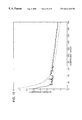
- FIG. 12 shows a graph illustrating how temporal prediction of the coefficients generated from a principal component analysis of deformation vectors reduced the entropy of the coefficients.
- FIG. 13 is a block diagram illustrating a computer system that acts as an operating environment for software implementations of the invention.
- Each column in matrix P represents a 3D position, such as a vertex position in a 3D mesh.
- the rows represent increments of time, such as frames in an animation sequence.
- the superscript for each element in the matrix identifies a 3D position, and in this notation corresponds to the column number.
- the subscript for each element in the matrix identifies a time increment, and corresponds to the row number in the matrix. If the matrix P is considered to be continuous in space, then it conceptually has an infinite number of 3D positions (columns) that completely describe the 3D surface of an object. In actuality, there are a finite number of the 3D positions for each time increment in an animation, corresponding to the geometric level of detail of the animation at that time.
- the matrix P is considered to be continuous in time, then there are conceptually an infinite number of rows.
- the 3D model is rendered into an output image at discrete times, and most likely at a periodic rate such as the frame rate.
- the update rate of an object can vary, and therefore, each row need not correspond to a frame in an animation sequence. In a more general representation, the rows simply correspond to time samples.
- Component G is the polygon interpolation or surface patch interpolation implemented in the low-level graphics hardware.
- the component S is an interpolation of the matrix through time.
- the time interpolation component specifies the discrete times at which the 3D model is rendered to an output image.
- V Each column of the vertex position matrix, V, describes the motion of a single vertex.
- V [ v 0 0 ⁇ v 0 n - 1 ⁇ ⁇ v m - 1 0 ⁇ v m - 1 n - 1 ] ⁇ continuous ⁇ ⁇ positions ⁇ ⁇ time ⁇ ⁇ samples
- the columns of the matrix V represent vertex positions. In particular, the superscript of each element in the matrix V identifies the vertex.
- the rows in the matrix V represent time samples. Subscripts of each element in the matrix V identify the time samples.
- V [ d 0 0 ⁇ d 0 k - 1 ⁇ ⁇ d M - 1 0 ⁇ d M - 1 k - 1 ] ⁇ trajectories ⁇ [ ⁇ 0 0 ⁇ ⁇ 0 N - 1 ⁇ ⁇ ⁇ k - 1 0 ⁇ ⁇ k - 1 N - 1 ] ⁇ influence
- the matrix V is factored into hierarchies of rigid objects. This is a smaller class of moving geometry than the more general V matrix above because it is limited to a specific type of motion, namely, a series of affine transforms performed on rigid bodies.
- V R [ A 0 0 ⁇ A 0 R - 1 ⁇ ⁇ ⁇ A m - 1 0 ⁇ A m - 1 R - 1 ] ⁇ affine transformations ⁇ diag ⁇ ( V ⁇ 0 ⁇ ... ⁇ ⁇ V ⁇ R - 1 ) ⁇ rigid ⁇ ⁇ bodies
- the left matrix represents affine transformations, with each row corresponding to a frame of animation, and each column corresponding to an affine transform of a rigid body.
- the affine transformations in the left matrix are the only changing terms and are updated for each frame.
- the rigid bodies shown above each consist of a set of vertices forming a rigid structure and having a column of affine transforms associated with it.
- the geometry interpolation component consists of an interpolation function for each rigid body that is used to interpolate attributes stored at vertices in the rigid body to output device coordinates.
- immediate-mode architectures There are two primary types of graphics rendering architectures: immediate-mode architectures and retained-mode architectures.
- Immediate-mode architectures re-send the entire vertex and geometric connectivity matrices each frame. This process can require a great deal of bandwidth because the large amount of data that needs to be sent to a 3D geometry rendering subsystem for each frame.
- Retained-mode architectures send the vertex and geometric connectivity matrices just once for a sequence of frames, and encode the changing affine transformation used to instruct the 3D rendering subsystem how to modify the position of the rigid bodies for each frame.
- More general graphics architectures overcome this limitation on the motion of the rigid bodies by supporting more general parameterized deformations.
- Examples of more general 3D motion models include inverse-kinematic linkages with free-form deformation lattices. This form of motion model is used widely for character animation.
- the following expression illustrates how the general time-dependent geometry matrix is factored for this more general motion model.
- the factors of the time-dependent geometry matrix include a matrix of deformation functions F, a series of rigid bodies V, and corresponding series of geometry interpolation functions for each of the rigid bodies G.
- V FFD [ F 0 0 ⁇ F 0 R - 1 ⁇ ⁇ ⁇ F m - 1 0 ⁇ F m - 1 R - 1 ] ⁇ deformation ⁇ diag ⁇ ( V ⁇ 0 ⁇ ... ⁇ ⁇ V ⁇ R - 1 ) ⁇ rigid ⁇ ⁇ bodies
- the deformation functions in the matrix on the left typically have a small number of parameters that define the motion of a set of vertices that form a rigid body. These motion parameters for each deformation function are sometimes splined through time or are computed from user input to determine the position of a rigid body for a frame in an animation sequence.
- the multiplication of a deformation function F with a corresponding rigid body V indicates the application of the deformation function F to the vertices of the rigid body.
- V FFD [ f 0 0 ⁇ f 0 k ⁇ ( R - 1 ) ⁇ ⁇ ⁇ f m - 1 0 ⁇ f m - 1 k ⁇ ( R - 1 ) ] ⁇ deformation vertices ⁇ diag ⁇ ( v 0 0 ⁇ v 0 R - 1 ) ⁇ ⁇ v k - 1 0 ⁇ v k - 1 R - 1 ⁇ parametric ⁇ ⁇ coordinates of ⁇ ⁇ rigid ⁇ ⁇ bodies
- V KL [ w 0 0 ⁇ w 0 k - 1 ⁇ ⁇ w M - 1 0 ⁇ w M - 1 k - 1 ] ⁇ weight ⁇ [ v ⁇ 0 0 ⁇ v ⁇ 0 N - 1 ⁇ ⁇ v ⁇ k - 1 0 ⁇ v ⁇ k - 1 N - 1 ] ⁇ mesh ⁇ ⁇ basis ⁇ ⁇ vectors
- Another widely used technique is to use “skinning” weights ⁇ j on each vertex to determine how the moving “bone” coordinate frames C i deform the mesh. Typically, most of the weights are zero, so the per-vertex weight matrix is sparse.
- the advantage to this technique is that a single rest shape can be deformed by a set of coordinate frames embedded near the region of interest. The inverse of the initial frame is pre-pended to the current coordinate frame to get the “bone” coordinate frame.
- V Skin [ C 0 0 ⁇ C 0 R - 1 ⁇ ⁇ C m - 1 0 ⁇ C m - 1 R - 1 ] ⁇ “ bone ” ⁇ ⁇ frames ⁇ [ ⁇ 0 0 ⁇ I ⁇ ⁇ 0 n - 1 ⁇ I ⁇ ⁇ ⁇ R - 1 0 ⁇ I ⁇ ⁇ R - 1 n - 1 ⁇ I ] ⁇ per ⁇ - ⁇ vertex ⁇ ⁇ weights ⁇ diag ⁇ ( v 0 ⁇ ⁇ ... ⁇ ⁇ v R - 1 ) ⁇ rest ⁇ ⁇ shape ⁇ ⁇ vertices
- Time dependent geometry may also be represented through the motion of selected control points in a 3D space, along with an association between these control points and the vertices in a mesh.
- U.S. patent application Ser. No. 09/093,590 entitled, “Method And System For Capturing And Representing 3d Geometry, Color And Shading Of Facial Expressions And Other Animated Objects,” by Brian Guenter, Cindy Marie Grimm, and Henrique Sarmento Malvar (Guenter et al.), which is hereby incorporated by reference in its entirety.
- the motion of the control points is applied to the associated vertices to deform the mesh.
- the motion of a control point from one frame to another is referred to as a trajectory.
- Guenter et al used control points to encode time-varying geometry representing a human face. Guenter et al recovered the motion of an actor's face by attaching fiducial “dots” and then using vision techniques to recover the motion of the dots. Guenter et al also captured a static 3D mesh representing the actor's face in a rest position using a conventional 3D capture system.
- V Face V 0 + [ d 0 0 ⁇ d 0 k - 1 ⁇ ⁇ d M - 1 0 ⁇ d M - 1 k - 1 ] ⁇ dot ⁇ ⁇ trajectories ⁇ [ ⁇ 0 0 ⁇ ⁇ 0 N - 1 ⁇ ⁇ ⁇ k - 1 0 ⁇ ⁇ k - 1 N - 1 ] ⁇ dot ⁇ ⁇ influence
- V Face V 0 + [ w 0 0 ⁇ w 0 L - 1 ⁇ ⁇ w M - 1 0 ⁇ w M - 1 L - 1 ] ⁇ dot ⁇ ⁇ coefficients ⁇ [ b 0 0 ⁇ b 0 k - 1 ⁇ ⁇ b L - 1 0 ⁇ b L - 1 k - 1 ] ⁇ dot ⁇ ⁇ basis ⁇ [ ⁇ 0 0 ⁇ ⁇ 0 N - 1 ⁇ ⁇ ⁇ k - 1 0 ⁇ ⁇ k - 1 N - 1 ] ⁇ dot ⁇ ⁇ influence
- This encoding scheme uses key shapes for the dot trajectories and then applies the motion of the dots to the rest of the vertices.
- the first step is to decide which columns of the vertex matrix V should be encoded in local coordinate systems.
- the modeling package can provide this information.
- Several current animation packages use “bones” and “skinning”, in which coordinate frames are weighted to produce the final vertex position.
- For generic animations output of simulations, shape cameras, etc.
- This clustering problem is common in learning, vector quantization, and other compression techniques. In our case, the vectors consist of the columns of the vertex matrix.
- the problem is to decide how many clusters are needed and which vertices should belong to each cluster.
- a further issue is to decide the class of deformation for each cluster.
- the cluster segmentation problem is as follows: Given vertex matrix V, return number of clusters, ncluster, and a list of cluster assignments for each vertex. Multiple assignment is allowed, so that each vertex may belong to a set of clusters and have an associated weight. Each cluster has an associated time-varying coordinate frame C that is given or calculated based on the vertices that are members of the cluster.
- v j ⁇ ( t ) ⁇ k ⁇ w k j ⁇ C k ⁇ ( t )
- the prototype segmentation algorithm uses a greedy clustering approach based on the triangles of the original mesh.
- a set of seed triangles is chosen at random. All of the triangles can be used as seed triangles, if desired, but the experiments below used approximately 10% of the original triangles in the mesh.
- the coordinate-frame trajectories of the seed triangles are compared and the clusters combined if within a given tolerance.
- the trajectories of the vertices are projected to the local coordinate system of each of the resulting clusters and classified according to the quality of the match throughout the trajectory.
- Geometric transform coding refers to a method for compressing time-dependent geometry by approximating the motion of 3D geometry with a geometric transform and then encoding the difference between transformed 3D geometry and the actual position of the 3D geometry for selected time samples throughout an animation sequence. These time samples correspond to the times in the animation sequence where the position of the object is updated (not necessarily every frame).
- the time-dependent geometry of an animation sequence is expressed as a series of 3D meshes, each identifying a set of vertex positions at a particular time sample in an animation.
- a specific example of this form of time-dependent geometry is the vertex position matrix V described above.
- the geometric transform coding method begins by selecting a base mesh. It then determines a geometric transform between the base mesh and each of the meshes in the animation. To compress time-dependent geometry, this method determines the difference between a transformed base mesh and the actual mesh, called the residual.
- the geometric transform coding method is competitive with the special case where the time-dependent geometry is comprised of animated rigid bodies.
- the base mesh corresponds to the rigid body and the geometric transform corresponds to motion model applied to the rigid body, such as an affine transformation or lattice free-form deformation.
- motion model applied to the rigid body such as an affine transformation or lattice free-form deformation.
- time-dependent geometry for the animation sequence is created by applying the deformation function to a rigid body, then there will be no distortion.
- the geometric transform coding methods described below are more general because they can represent more general forms of motion and can be adapted to encode arbitrary meshes where the deformation function or the rigid body portions of the time-dependent geometry are not known at the time of coding.
- the geometric transform method quantizes and encodes the deformation parameters, the base mesh or meshes, and the residual.
- the time-dependent geometry matches one of the simpler subclasses (rigid body or lattice FFD), the residuals are zero and can be encoded with very low overhead.
- the geometric coding method can be used alone, or in combination with other compression techniques described below to take advantage of the coherence in the time-dependent geometry matrix V.
- One way to further take advantage of the temporal and spatial coherence in the time-dependent geometry matrix is to identify and encode coherence among the rows and columns of the matrix V.
- the methods for coding time-dependent geometry described below improve upon the compression inherent in simpler motion modules, and yet are applicable to more complex motion models while still being compatible with current 3D graphics rendering architectures.
- FIG. 1 is a block diagram illustrating an example of a mesh transform coder.
- FIG. 1 shows both the compressor 20 and the decompressor 40 to illustrate how the time-dependent geometry is encoded for transmission or storage and then decoded.
- There are three types of input to the compressor 20 The matrix V representing the positions of mesh vertices as they change over time, a base mesh V, and geometric transforms (“xfm”) that match the base mesh with meshes in the time-dependent matrix, V.
- the compressor quantizes and encodes the transformation parameters of the geometric transforms, the base mesh, and residuals. To minimize the distortion of the reconstructed meshes in the decompressor, the compressor computes the residual using quantized/de-quantized transformation and base mesh parameters.
- the base mesh in this encoder is intended to be a mesh of vertices representing a rigid body.
- the base mesh may not be provided to the coder and has to be derived from the stream of time-dependent geometry, V.
- the base mesh may be calculated by using a row of the matrix V as the base mesh, by taking an average of several rows of V as the base mesh, or by pre-computing the base mesh that results in the smallest combined bandwidth for the transformation parameters and the residuals.
- the latter approach is a non-linear optimization of both the transformation parameters and the base mesh at the same time.
- the geometric transforms (“Xfm”) illustrated as input to the compressor in FIG. 1 are sets of geometric transformation parameters used to transform the position of the base mesh to a new position at a selected time sample increments.
- the selected time increments typically correspond to frames in an animation sequence.
- the time increments may more generally correspond to time samples to be compatible with rendering architectures that enable objects to be updated at varying rates.
- the transformation parameters are used to transform the base mesh to a new position for each time sample, each sample has a corresponding set of transformation parameters.
- the transformation parameters represent a geometric transform such as an affine or a general free-form deformation that transforms the rigid body from its local coordinate system to the world coordinates of the animated graphics scene.
- the compressor 20 includes quantizer modules 22 , 24 for quantizing the transformation parameters and 3D position values in the base mesh, respectively.
- the compressor also includes de-quantizers 26 , 28 used to de-quantize the transformation parameters and 3D position values of the base mesh.
- the transform module 30 shown in the compressor applies the de-quantized transformation parameters to the de-quantized 3D position values to produce a transformed mesh approximating the current position of the time-dependent geometry.
- a subtractor module 32 then computes the difference between the values of the transformed base mesh and the corresponding elements of the matrix V. In particular, the subtractor module computes the difference between the de-quantized and transformed base mesh vertices and the vertices in the row of the vertex position matrix V for the current time sample.
- the output of the compressor 20 includes the quantized transformation parameters per time sample and the quantized base mesh, sent once at the beginning of the compressed data stream.
- the output also includes the quantized residual for each time sample computed in the quantizer 34 .
- the compressed data stream therefore, encodes the base mesh once for an animation sequence, and encodes transformation parameters in the residuals for several time samples in the animation sequence, such as each frame in the animation sequence.
- the compressed data stream can either be stored in persistent memory for later use or sent to a transmitter for transmission to another computer or rendering device.
- the decompressor 40 reconstructs time-dependent geometry for selected time increments from the compressed data stream.
- the decompressor reconstructs the matrix of vertex positions, one row at a time, for time samples in an animation sequence.
- the de-quantizers 42 , 44 , and 46 in the decompressor de-quantize the residuals, the transformation parameters, and the 3D position data of the base mesh, respectively.
- a geometric transform module 48 applies the de-quantized transformation parameters for the current time sample to the de-quantized base mesh to compute a transformed base mesh.
- An adder module 50 combines the transformed base mesh for the current time sample with the corresponding de-quantized residual for that time sample to compute the current 3D positions of the time-dependent geometry.
- the decompressor 40 can be used in on-line rendering applications where the compressed time-dependent geometry is retrieved and sets of vertex positions are reconstructed in sufficient time to present geometry to a 3D graphics rendering subsystem for rendering in an animation sequence.
- the time-varying transformation parameters are not available before the coding of the time-dependent geometry commences. This is especially the case in applications involving the coding of a more general matrix representing sets of time-dependent vertex positions that are not simply a rigid body transformed using a standard geometric transform such as an affine transformation or a free-form deformation.
- the compressor derives a series of transformations that best match a base mesh to the current mesh for selected increments of time in an animation sequence.
- a coder that derives the transformation parameters for a matrix representing time-dependent geometry with general, arbitrary motion. The example that is described and illustrated refers specifically to deriving affine transformations, but the same approach can be applied to other motion models as well.
- FIG. 2 is a block diagram of a base mesh transform coder that performs transformation matching to derive transformation parameters from time-dependent geometry.
- FIG. 2 shows a compressor module 60 and a de-compressor module 62 .
- the quantizer and de-quantizer modules shown in FIG. 1 are represented as dashed lines 62 - 68 in FIG. 2 .
- the inputs to the compressor 60 include the base mesh V 0 and a matrix of vertex positions, V, representing time-dependent geometry.
- the base mesh in the more general case is not necessarily known before coding begins.
- the base mesh may be derived from the matrix V.
- the base mesh may be selected by using a row of V, by taking an average of the rows of V, or by pre-computing the base mesh that results in the smallest combined bandwidth for the transformation parameters and the residuals as discussed above.
- the transformation parameters can also be derived from the matrix of vertex positions.
- a transform match module 70 in the compressor 60 determines the geometric transform that best matches the base mesh to each of the time-dependent meshes in the matrix V. Each of the rows in the matrix V corresponds to a mesh at a selected time.
- the transform match module 70 calculates transformation parameters for a geometric transform used to transform the base mesh to approximate the position of a mesh stored at a row in the matrix V.
- the compressor 60 includes a transform module 72 that applies de-quantized transformation parameters to de-quantized base mesh parameters to approximate the position of the current mesh.
- a subtractor module 74 then computes the difference between the 3D positions of the transformed base mesh and the current mesh to produce a residual.
- the residual, transformation parameters, and base mesh parameters are quantized and transmitted as shown in dash lines 64 , 66 , and 68 .
- the base mesh is only transmitted once for a typical animation sequence.
- the transformation parameters and a residual are computed for each time sample in the animation being encoded. Typically, this time sample corresponds to a frame in an animation sequence.
- the decompressor 62 of FIG. 2 represents a component used to decode a compressed data stream and reconstruct a stream of time-dependent geometry.
- the decompressor 62 also includes a transform module 80 and an adder module 82 .
- the transform module applies de-quantized transform parameters to a de-quantized base mesh to compute a transformed base mesh for a selected time sample.
- the adder module 82 takes the transformed base mesh and combines it with the residual mesh for that time to reconstruct a mesh.
- the transform module 80 and adder module 82 repeat this process for additional sets of transformation parameters and associated residual meshes.
- the implementation of the transform match module 70 depends, in part, on the motion model used to approximate the change the position between the base mesh and a corresponding mesh of the matrix, V. For example, if the 3D motion is estimated based on an affine transformation model, the transform match module 70 computes affine transformation coefficients that result in the closest match between the transformed base mesh and a corresponding mesh at a selected point in time.
- the expression for computing the transformation coefficients may be expressed as follows:
- a k is the desired 4 ⁇ 4 matrix used to transform base mesh V 0 to V k, the current row of the general matrix V.
- One technique for finding the transformation coefficients that represent the best least-squares solution is to compute the singular value decomposition (SVD) of the base mesh, V 0 , and apply the decomposition of the base mesh to the current row of V. This approach can be computationally expensive for large matrices.
- the transform match module 70 can be adapted to use one or more of the optimizations discussed below.
- One optimization is to make the computation using lower level-of-detail vertex matrices for the base mesh and the current mesh.
- the lower level-of-detail matrices can be used to compute an approximation to the best least-squares solution, which can then be applied to the full matrix.
- V 0 V 0 T matrix is singular or poorly conditioned.
- additional vertices are added to augment the rest shape vertices V 0 and the per-frame vertices V j to remove the degeneracy.
- the additional vertices are derived from the triangles associated with the vertex set, by offsetting the center of each triangle along each triangle's normal.
- the geometric transformation used in the technique illustrated in FIG. 2 is an affine transformation
- the geometric transform coder can be modified to the form shown in FIG. 3 so that the geometric transform can be combined with the viewing transform.
- FIG. 3 is a block diagram illustrating an alternative base mesh transform coder that encodes the inverse geometric transform rather than the geometric transform.
- the residuals for each time sample are calculated in the coordinates of the transformed base mesh, instead of subtracting the transform base mesh from the current mesh in the local coordinates of the current mesh. This calculation is illustrated in the following expression:
- V k j ( a k j ) ⁇ 1 V k j ⁇ circumflex over (V) ⁇ 0 j
- the residual parameters ⁇ V k are computed as the difference between: 1) the current row of the matrix of vertex positions transformed to the coordinate space of the base mesh, and 2) the base mesh V 0 .
- the transformation parameters match the current mesh to the base mesh.
- the compressor 100 and de-compressor 102 in the inverse transform coder shown in FIG. 3 operate on the same input data and have similar components as the mesh transform coder of FIG. 2 .
- a transform match module 104 in the compressor computes transformation parameters that match the transformed current mesh with the base mesh.
- An inverse transform module 106 then applies de-quantized transformation parameters to the current mesh to transform the current mesh to the base mesh coordinates to compute the residual,
- a subtractor module 108 computes the difference between the corresponding elements of the transformed current mesh and the base mesh.
- the compressor repeats this process for each row in the input matrix V to produce a compressed geometry stream.
- the decompressor operates on a quantized residual, quantized transform parameters, and the quantized base mesh.
- an adder module 110 in the decompressor 102 combines the de-quantized parameters of the base mesh with the quantized residual.
- a geometric transform module 112 in the decompressor takes as input the de-quantized transforms that combine the viewing transform for the current frame with the 3D deformation transform computed in the compressor.
- the transform module 112 transforms the current mesh from base mesh coordinates to world coordinates, and then from world coordinates to viewing coordinates. This approach allows the transformation module in the compressor to combine the 3D transform computed in the transform matching with a standard modeling and camera transformations of the graphics rendering pipeline.
- the base mesh for some forms of time-dependent geometry is a pre-defined mesh representing a rigid body while in other applications, the mesh is derived from a general vertex of matrix positions.
- a geometric transform coder can be adapted to use the mesh of the previous frame as base mesh for the current frame. This approach adds a feedback loop that uses the mesh of the previous frame as a predictor of where the mesh will be in the current frame. It is important to note that this form of prediction is different than row prediction performed on the matrix of vertex positions because the transformation is in 3D coordinate space instead of N-dimensional vector space. However, as explained in further detail below, both row and column prediction can be used to further compress a matrix of 3D position data such as the residual or the base mesh.
- FIG. 4 illustrates a block diagram of a mesh transform coder that uses a mesh computed for a previous time sample as the base mesh for the current time sample.
- FIG. 4 shows both the compressor 120 and de-compressor 122 for this type of coder.
- the base mesh for each current frame is the constructed mesh from the previous frame.
- the compressor In addition to computing the residual as in the other mesh coders, the compressor also reconstructs and maintains a copy of the re-constructed mesh from the previous time sample.
- the transform match module 124 finds the best transformation to map the approximate vertices V′ of the previous frame to the mesh of the next frame. Since the current mesh is typically more similar to the previous frame's mesh than a single base mesh for the entire animation sequence, this approach tends to result in smaller residual values.
- the transform match module 124 operates on the approximate mesh stored temporarily in “delay” memory 126 and finds transformation parameters that best match the previous mesh with the current mesh. As in FIGS. 2 and 3, the dashed lines represent pairs of quantizers and de-quantizers.
- the compressor quantizes the transformation parameters from the transform match module 124 . Quantized transformation parameters form part of the compressed data stream 128 and are also fed to a de-quantizer before being used to compute the residual in the compressor.
- the transformation module 130 applies the de-quantized transformation parameters to the approximate mesh computed for the previous frame to compute a transformed mesh that estimates the position of the mesh of the current frame.
- a subtractor module 132 in the compressor computes the residual as the difference between the transformed mesh of the previous frame and the current mesh. The residual is then quantized, and the quantized residual forms a second part of the compressed data stream 134 along with the quantized transformation parameters 128 .
- a feedback loop in the compressor reconstructs the approximation of the current mesh and temporarily stores the approximate mesh of the current frame in memory 126 .
- adder module 136 combines the residual 3D position data computed for the current frame with the transformed version of the previous frame and stores the resulting approximation of the current mesh in memory 126 .
- the compressor keeps a copy of the current approximation of the vertices for one time increment, e.g., a frame, so that it can be used as a predictor of the mesh for the next time increment in the time-dependent geometry matrix, V.
- the decompressor 122 also has a feedback loop that delays the most recently computed vertices for one time increment so that they can be used as a predictor for the next set of vertices.
- a transform module 140 in the decompressor applies de-quantized transformation parameters to the previously constructed mesh, temporarily stored in memory 142 .
- the output of the transformation module 140 is the mesh of the previous frame transformed to the current mesh.
- An adder module 144 combines this transformed mesh with the de-quantized residual for the current frame from the compressed data stream to construct the current approximate vertices, V′.
- the inverse transform coding method described above and illustrated in FIG. 3 can also be used in the feedback coder shown in FIG. 4 .
- the transform match module 124 transforms the current mesh input into the coordinates of the approximate mesh of the previous frame.
- the compressor then computes the residual as the difference between the current mesh transformed to the coordinates of the previous frame and the approximate mesh for the previous frame.
- the compressor and decompressor reconstruct a current mesh from the residual by combining the approximate mesh of the previous frame with the transformed current mesh.
- the resulting 3D position data is then transformed to its position in the current frame using the transformation parameters computed in the transformation match module 124 .
- the 3D transformation cannot be combined with the camera transformation.
- the current mesh must be transformed, without the camera transformation, and stored separately for use in predicting the position of the mesh for the next frame.
- a stream of time-dependent geometry can be expressed as a matrix of 3D geometric position data, where each row corresponds to a time sample such as a frame in an animation sequence, and each column is associated with a 3D position.
- the residual matrix that results from subtracting the original matrix from the compressed matrix has the same form as the original matrix, and the compression techniques described in this section apply equally well to the residual matrix as to the original vertex matrix.
- Temporal prediction can be performed by pairing each row with another row or a reference row, computing the difference between each corresponding element in the two rows, and then encoding the difference between the rows by, for example, quantizing the difference values.
- Geometric prediction can be performed on the columns using a similar approach. Also, since the geometric connectivity among the 3D positions associated with each column is typically specified independently, the columns can be sorted such that the values of the corresponding elements in neighboring columns is as similar as possible.
- FIG. 5 is a block diagram illustrating an example of a matrix prediction coder including both a compressor 160 and decompressor 162 .
- the compressor 160 operates on a time-dependent geometry stream, which in this case, is the matrix of vertex positions, V.
- a sort module 162 in the compressor positions the columns or rows (or both) such that the neighboring columns/rows have corresponding elements that are more similar than the original matrix.
- the sort module 162 sorts the columns to make the neighboring vertex paths as similar as possible. This sorting process on the geometry attempts to place portions of the geometry that have coherent motion together.
- the 3D geometry is comprised of a series of rigid bodies, the columns are arranged into groups of rigid points that move together.
- the sort module 162 operates on a measure of column similarity to find groups of columns that have similar motion.
- One such measure of similarity is to use the inner product of the mean-removed columns.
- the sorter may then use the resulting similarity measure to sort the columns.
- the similarity between columns i and j is computed in two ways: raw column dot product, V i ⁇ V j , and sum of squared distances between column elements ( ⁇ (V k i ⁇ V k j ) 2 ) 1 ⁇ 2 .
- Columns of vertices that are most similar are placed adjacent to each other. Starting at the left and moving to the right, the column sorter finds the most similar column from the remaining columns and swaps that column to be just to the right of the current column. Because the triangle list uses vertex indices and since each vertex is represented with a column, there is a level of indirection between the location in the matrix and the use of the column on output. This makes the column re-ordering transparent to the decoder. The encoder renumbers the indices in the triangle list to correspond to the sorted columns in the vertex matrix.
- Row sorting can be done in a similar way to column sorting.
- Vertices that move in similar paths are considered to be similar.
- This particular sort involves a linear sort on a 2D surface, so the best possible result is a path through the vertex matrix that fills the surface similar to a Peano curve, which is one class of “space-filling” curves.
- Peano curve which is one class of “space-filling” curves.
- a later section describes a sorting technique in more detail that improves coherence among the columns by clustering neighboring vertices via edge contractions.
- the sort module 163 generally represents the process of sorting rows/columns of the matrix to improve the coherence of neighboring rows/columns.
- the sort module 163 performs a sort on the column data, it updates the geometric connectivity data for the matrix so that it properly refers to the appropriate columns in the sorted matrix.
- the geometric connectivity data 164 defines the connectivity among vertex positions in the matrix. The data defines subsets of vertices within a mesh that are connected together and also maintains a reference between the vertex positions in its structure and the corresponding vertex positions in the matrix, V.
- the sort module 163 changes the order of the columns, it updates the connectivity information so that the vertex position in the connectivity data refers to the appropriate column in the matrix, V.
- the compressor 160 also performs temporal prediction on the rows of the matrix of vertex positions.
- the neighboring rows in the matrix V are already arranged such that neighboring rows contain corresponding elements that are most similar.
- the compressor 160 performs row/column prediction by computing the difference between each corresponding element between a reference row/column and another row/column. Once sorting is complete, predictor module 166 computes the difference between each corresponding element in pairs of adjacent rows to perform row prediction, and between each corresponding element in adjacent columns to perform column prediction. The output of the prediction module 166 is a matrix of difference values. These difference values can then be quantized in quantizer module 168 .
- the decompressor 162 in FIG. 5 performs the reverse of the operations of the compressor 160 .
- dequantizer module 170 dequantizes the matrix of difference values.
- the matrix of difference values is then reconstructed to compute the original rows and columns of the sorted matrix in the inverse predictor module 172 .
- the reorder module 174 reorders the columns in the case where they are sorted for column prediction, and also reorders the rows where they are sorted for row prediction.
- the geometric connectivity data 176 is used to reorder the columns.
- the ordering of the rows as represented in the temporal data 178 is used to ensure that the geometric data is in the proper time sequence.
- a matrix of time-dependent geometric data can be decomposed into a matrix of basis vectors and another matrix of weights using principal component analysis.
- Row/column prediction in this case, can be performed on the matrix representing the weights. It is also possible to use prediction on a matrix of the residual values computed in a mesh coder and on the base mesh.
- Another method for compressing a matrix representing time-dependent geometry is to decompose the matrix into basis functions and weights using principal component analysis.
- Techniques for finding the best set of basis vectors for a matrix go by many names: PCA (principal components analysis), KL-transform (Karhunen-Loève), SVD (singular value decomposition.), etc.
- a basis vector is given by a singular value, s i , and a row W i .
- Each column U i gives the corresponding weights per frame.
- V W [ w 0 0 ⁇ w 0 k - 1 ⁇ ⁇ w M - 1 0 ⁇ w M - 1 k - 1 ] ⁇ weights ⁇ [ v ⁇ 0 0 ⁇ v ⁇ 0 N - 1 ⁇ ⁇ v ⁇ k - 1 0 ⁇ v ⁇ k - 1 N - 1 ] ⁇ mesh ⁇ ⁇ basis ⁇ ⁇ vectors
- the matrix on the left represents the weights, which are sometimes also referred to as coefficients.
- the matrix of the weights shown above has several rows corresponding to time increments and columns representing geometric positions.
- the matrix on the right representing the mesh basis vectors includes a row for each time increment and columns representing basis vectors. If the number of important basis vectors is small, good compression can result by encoding and transmitting just the most important basis vectors, and then transmitting the weights per frame plus the residual from the rest of the basis vectors that were not encoded explicitly.
- the basis vectors given by D S W S are then expanded by the Progressive Mesh vertex split records as needed to get a basis for the fine-detail mesh.
- the weights given by U S are expanded by the detail records in time (given by knot insertion or wavelet details).
- V K U K D K W K T with U K of size nframe ⁇ K and V K of size K ⁇ nvertex.
- FIG. 6 is a block diagram illustrating a mesh basis coder that uses principal component analysis to compress a time-dependent geometry stream.
- the mesh basis coder shown in FIG. 6 projects a matrix of vertex positions, V, to a set of mesh basis vectors and then compresses the basis coefficients and the residual.
- a basis projection module 202 decomposes the current mesh into basis coefficients and basis vectors.
- Quantization module 204 quantizes the basis coefficients, which become part of the compressed data stream 206 .
- Dequantizer module 206 dequantizes the basis coefficients for the current mesh.
- Basis synthesis module 208 reconstructs the current mesh from the dequantized basis coefficients and basis vectors.
- subtractor 210 computes the difference between the reconstructed mesh and the current mesh for each corresponding element.
- quantizer 212 quantizes the residual, and a quantized residual becomes a second part of the compressed data stream 214 along with the quantized basis coefficients 206 .
- the decompressor 220 reconstructs the current mesh from the coded residual and basis coefficients.
- Dequantizer 222 reconstructs the basis coefficients and dequantizer 224 reconstructs the residual.
- Basis synthesis module 226 approximates the current mesh by applying the dequantized basis coefficients to the basis vectors. Adder unit 228 then combines the approximate mesh from the basis synthesis module 226 with a dequantized residual to compute a reconstructed mesh.
- Mesh simplification techniques can be used to convert a matrix of 3D time-dependent geometry into a hierarchy of mesh refinements.
- Some examples of mesh simplification techniques include progressive meshes as described in “Progressive Meshes,” Hugues Hoppe, pp. 99-108, SIGGRAPH '95 and “View-Dependent Refinement of Progressive Meshes,” Hugues Hoppe, pp. 189-198, SIGGRAPH '97.
- progressive meshes as described in “Progressive Meshes,” Hugues Hoppe, pp. 99-108, SIGGRAPH '95 and “View-Dependent Refinement of Progressive Meshes,” Hugues Hoppe, pp. 189-198, SIGGRAPH '97.
- Quadric error mesh simplification is described in “Surface Simplification Using Quadric Error Metrics,” Michael Garland and Paul S. Heckbert, pp. 209-216, SIGGRAPH '97.
- mesh simplification techniques may be used as well, such as mesh simplification used in the MetaStream 3D file format from MetaCreations Corporation.
- level-of-detail control in the compression of time-dependent geometry.
- level-of-detail control reduces the cost of encoding the time-dependent geometry considerably.
- the motion of the simplified geometry is a good approximation of the motion represented in the detailed mesh, and therefore, a simplified version of the geometry can be used to compute compression parameters such as affine transforms in a mesh transform coder and basis vectors in basis decomposition coder.
- level-of-detail control enables the compressor to change the topology of the mesh through time.
- the time-dependent geometry of the object can be represented with higher or lower level-of-detail.
- a 3D object or a part of an object can be represented at varying levels of detail depending on its importance in an animation sequence at selected points in time.
- mesh simplification can be extended to create a data structure representing time-dependent geometry as a pyramid in space and time.
- the pyramid represents the hierarchy of a 3D object's level-of-detail in both space and time.
- This space-time pyramid can be used as a form of compression because the hierarchical representation of the time-dependent geometry of an object is smaller than the original time-dependent geometry consisting of a mesh for each frame in an animation.
- the hierarchical representation is also efficient for transmission because refinement and coarsening records used to refine or coarsen the hierarchical representation can be transmitted instead of transmitting a mesh for each frame.
- the hierarchical representation also makes other forms of compression described above more efficient because they can be designed to operate at the appropriate level of detail in the space-time pyramid.
- the hierarchical representation of the space-time pyramid can be represented using a series of expansion records.
- This local encoding has a number of benefits, including hierarchical control of the mesh shape and hierarchical quantization (where the fine detail is coded with fewer bits).
- the benefits are similar to the benefits achieved in subdivision schemes, such as the ones described in “Interpolating Subdivision for Meshes with Arbitrary Topology”, Denis Zorin, Peter Schroeder, and Wim Sweldens, pp.
- the hierarchy of the space-time pyramid is created by factoring the matrix of time-dependent vertex positions into: 1) contracted sets of geometry, and 2) expansion records.
- the following expression shows how the matrix of vertex positions is factored into a matrix of contracted vertex columns and vertex expansions.
- V E [ v 0 0 ⁇ ⁇ ... ⁇ ⁇ v 0 j 1 - 1 ⁇ v m - 1 0 ⁇ ⁇ ... ⁇ ⁇ v m - 1 j 1 - 1 ⁇ v 0 j 1 ⁇ ⁇ ... ⁇ ⁇ v 0 j 2 - 1 v m - 1 j 1 ⁇ ⁇ ... ⁇ ⁇ v m - 1 j 2 - 1 ⁇ ⁇ ⁇ v 0 j N - 1 ⁇ ⁇ ... ⁇ ⁇ v 0 n - 1 ⁇ v m - 1 j N - 1 ⁇ ⁇ ... ⁇ ⁇ v m - 1 n ] ⁇ contracted ⁇ ⁇ vertex ⁇ ⁇ columns ⁇ [ D ] ⁇ vertex ⁇ ⁇ expansions
- Each of the contracted vertex columns represents a delta between a pair of neighboring levels in the spatial hierarchy.
- the vertex expansions include an expansion record for each corresponding contracted vertex column indicating how the contracted vertex column can be expanded to restore to an approximation of the original matrix.
- V T [ T ] ⁇ time ⁇ ⁇ exp ⁇ ⁇ ansions ⁇ [ v 0 0 ⁇ ⁇ ⁇ ⁇ ⁇ v k 1 - 1 0 ⁇ v 0 n - 1 ⁇ ⁇ ⁇ ⁇ ⁇ v k 1 - 1 n - 1 v k 1 0 ⁇ ⁇ ⁇ ⁇ ⁇ v k 2 - 1 0 v k 1 n - 1 ⁇ ⁇ ⁇ ⁇ v k 2 - 1 n - 1 ⁇ ⁇ v k M - 1 0 ⁇ ⁇ ⁇ ⁇ v m - 1 0 ⁇ v k M - 1 n - 1 ⁇ ⁇ ⁇ ⁇ ⁇ v m - 1 0 ⁇ v k M - 1 n - 1 ⁇ ⁇ ⁇ ⁇ ⁇ v m - 1 n ] ⁇ contracted ⁇
- the rows represent deltas between neighboring pairs of a hierarchy in the time dimension.
- the time expansions T include time expansion records corresponding to each contracted vertex row that define how the corresponding row can be expanded to restore it to an approximation of the original matrix.
- the matrix of vertex positions can be factored into time expansions, a matrix of contracted vertex blocks, and vertex expansions as set forth in the following expression.
- V TE [ T ] ⁇ time ⁇ ⁇ expansion ⁇ [ v _ 0 0 ⁇ v _ 0 N - 1 v _ 1 0 v _ 1 N - 1 ⁇ ⁇ v _ M - 1 0 ⁇ v _ M - 1 N ] ⁇ contracted ⁇ ⁇ vertex ⁇ ⁇ blocks ⁇ [ D ] ⁇ vertex ⁇ ⁇ expansions
- the contracted vertex blocks represent deltas between a neighboring column and row in the space-time hierarchy.
- the current implementation uses a mesh refinement technique to create a series of edge-contraction/vertex-split records.
- edges interconnecting the vertex positions are collapsed to create a mesh with fewer vertices.
- vertex positions are split into additional positions to create a more detailed mesh.
- the matrix above represents a vertex expansion list.
- the top row of the matrix denotes splits in the spatial hierarchy of the time-dependent geometry. Subsequent rows in the matrix correspond to increments of time. Columns in the matrix correspond to delta values between neighboring levels of hierarchy in the spatial domain.
- the contraction coefficients run from right to left and, conversely, expansion coefficients run from left to right. Due to the structure of the refinement procedure, the magnitudes of the delta vectors stored at each element in the matrix decrease from left to right. Intuitively, this is because the first edges to be collapsed perturb the original mesh the least, by design. There is more signal strength on the left hand side of the matrix, and it becomes progressively smaller from left to right in the matrix.
- the refinement matrix can be used to improve the efficiency of the compression methods described above, and specifically, the geometric transform method and the basis decomposition method.
- the current implementation of the mesh refinement method converted an original mesh having approximately 3000 vertices into a refinement matrix.
- the affine transformation coefficients computed in the prototype geometric transform coder and the basis vectors as computed in the prototype basis decomposition coder became more tractable by using only 300-1000 elements on the left hand side of the refinement matrix. In effect, this mesh simplification performs a low-pass filter on the mesh in the perceptual advantageous way.
- the particular ordering of the elements in the expansion list is determined by the optimization criteria used during the mesh simplification process.
- the current implementation uses the quadric-error measure Progressive Mesh technique on the mesh of the first frame of the animation and applies the result to the rest of the rows in the original time-dependent matrix of the geometry data. This approach is reasonably fast and accurate. However, in the dynamic compression context, this particular ordering may not be optimal for the entire animation sequence. To find a more optimal ordering, the dependency graph of vertex splits can be used to re-order the expansion records with compression and fidelity measures such as the quadric-error measure used at the same time.
- the dependency graph of vertex splits determines which split columns can be reordered and which cannot due to dependencies on splits of vertices further to the left in the matrix.
- a more general approach would be to search for the particular Progressive Mesh (PM) expansion that gives the best compression/best visual quality.
- PM Progressive Mesh
- the Progressive Mesh approach finds the best sequence of vertex collapses to match the spatial geometry of the lower level of detail mesh to the spatial geometry of original mesh.
- time-dependent geometry to measure the quality of a particular PM requires summing the error in the geometry over the time dimension (in other words, over the rows of original vertex matrix V) for each level of detail of the PM.
- a PM can be computed for each row of V and then tested over all the rows of V for geometric accuracy.
- a PM can be computed for the average mesh obtained by taking the average of the columns of V.
- the space-time coder takes the example of a human character. From a distance, all that is needed is the translation and rotation of the whole body at low polygon count, with limbs rigidly fixed. As the character gets closer, the gross movement and shape of the limbs is needed to convey the proper perception of the motion. As the character gets even closer, the fine detail in the movement and shape of the face and other muscles becomes important. As the character then recedes, less detail is needed, in reverse order of the steps listed above. To achieve the appropriate gradual increase and then decrease in detail, the space-time codec transmits first a simple geometric representation of the model and a simple version of the animation. Then, based on the viewpoint of the client, the server streams down spatial and temporal detail updates as needed.
- the server refers to the system entity that acts as the source of time-varying geometry
- the client refers to the entity where playback occurs.
- the server and client may be software processes executing on the same or different processors.
- the server may be a software module executing on a host processor and the client may be a graphics co-processor in a computer system.
- the server may be software executing on a first computer, and the client may be a hardware device or software module executing in a second computer, which is connected to the first computer via a modem connection, a local area network or wide area network.
- the input is a densely time-sampled set of meshes M( 0 ), . . . , M(n ⁇ 1).
- the positions of the vertices can be considered as a matrix, V.
- Each column j of V is a trajectory of a coordinate through time.
- the space-time pyramid is a decomposition of V along the two dimensions of space (across the columns) and time (across the rows).
- the top and bottom of the cube remain as squares aligned to the x-z plane, but the sides of the cube curve as the y-twist of the top increases and decreases as shown in the top animation sequence in FIG. 7 .
- the animation is sampled in time at 60 Hz to get 60 initial meshes M( 0 ), . . . , M( 59 ).
- the top vertices are V 0 to V 3 and the bottom vertices are V 4 to V 7 .
- the rest of the vertices encode the twisting sides of the cube.
- the first step is to segment the mesh into factors that are animated independently and then combined with an animation expression.
- the desired animation expression is:
- Each of the k terms encodes a segment of the mesh with a different speed of rotation.
- the bottom segment matches the bottom of the cube and is stationary. Going from bottom to top, the speed of each segment gradually increases up to the top segment that matches the y-rotation of the top of the cube.
- the detail terms can be encoded in space or in time, as described in the next two paragraphs.
- the job of the encoder is to choose, at each step in the encoding sequence, the dimension with the most coherence. This is performed by exploring both dimensions and choosing the detail smoothing with the best prediction.
- each segment is coded using progressive mesh edge collapses using a typical mesh, which is either the first in the sequence or the initial unanimated mesh (also called the rest shape).
- An edge collapse combines two columns of V into a single column and encodes a delta to recover the original columns.
- each segment is coded in two ways.
- the vertex positions and animation coefficients are splined through time.
- Higher level of detail is added by inserting a new spline vertex between two existing ones to give the motion a new local feature.
- One form of inserting such a vertex is called knot insertion.
- a time-edge collapse combines two rows in the current segment and encodes a row delta to recover the original rows.
- wavelets are used and higher level of detail is added with more detail coefficients.
- the client side representation is blended with the new detail coefficients while retaining the smoother coefficients.
- the data structures are categorized based on whether they reside on the server or client, or are sent between the client and server during selective playback of a 3D-animation sequence.
- the server may communicate the following data structures to the client to update the animation on the client during selective playback.
- idim(seg_ndim-1) // list of active dimensions triset imesh itri iv0 iv1 iv2 // triangle vertex indices tridel imesh itri // delete indexed triangle // Vertex initialization and deletion vset imesh iv v(0) v(1) . . . v(ndim-1) // initialize vertex position, normal, uv's, etc voffset imesh iv ivsrc dv(0) dv(1) . . .
- UpdateTriangle ⁇ int m_itriangle // index of triangle to add/update int m_aivertex[3]; // list of vertex indices ⁇ ; struct UpdateDeleteTriangle ⁇ int m_itriangle; ⁇ ; struct UpdateSetVertex ⁇ int m_ivertex; // index of vertex to add/set float m_afvertex[0]; // size ndim array of vertex values ⁇ ; struct UpdateOffsetVertex ⁇ int m_ivertex; // index of vertex to add/offset int m_ivertexSource // index of source vertex float m_adfvertex[0]; // size ndim array of delta vertex values ⁇ ; struct UpdateDeleteVertex ⁇ int m_ivertex; // index of vertex to delete ⁇ ; struct UpdateSegmentActiveVertices ⁇ int m
- UpdateBlock *m_pStep[9] // blocks of update records corresponding to finer and coarser levels of detail in space and time int m_nupdate; // number of update records in this block Update **m_apupdate; // array of pointers to update records ⁇ ; struct ServerMeshAffine1D ⁇ MeshAffine1D m_meshClient; // the server keeps track of what the client has to compute the appropriate update sequences UpdateBlock *m_pUpdateBlock; // current position in the space-time pyramid ⁇ ;
- server ⁇ client spatial resolution current view server ⁇ client spatial update records (e.g., progressive- mesh style vertex splits and edge collapses)
- server ⁇ client temporal resolution current time interval server ⁇ client temporal update records (parameter curve knot insertions and deletion, or blocks of wavelet detail coefficients)
- the client sends the server the current viewpoint of a segment along with the desired spatial resolution.
- the spatial resolution indicates the geometric level of detail at which the client will render the segment.
- the server provides the spatial update records that enable the client to extract the desired geometric level of detail from the space-time pyramid.
- the client sends the temporal resolution and current time interval to the server.
- the server sends the temporal update record(s) that enable the client to extract the desired temporal level of detail from the space-time pyramid.
- Time has been used throughout this document as a representative dimension. Instead of just playing back a linear sequence, this dimension may be used for interactive controls.
- this dimension may be used for interactive controls.
- the detailed animation of an elbow bending is parameterized by the joint angle of the elbow.
- the user can control the highly detailed animation. This is useful in interactive applications such as games.
- the animation of the bending elbow may be represented in a space-angle matrix structure.
- Each column represents a position in the 3D mesh of the elbow object and the rows represent an angular position of the elbow joint.
- the joint angle may be represented in a hierarchical fashion from a low level of detail (e.g., few joint angle samples) to a high level of detail (e.g., many joint angle positions representing detailed bending of the elbow).
- the client requests an appropriate level of detail for angular motion, and in response, the server sends the corresponding update records for the joint angle dimension (either coarsening or refining) to animate the movement of the elbow at the appropriate level of detail.
- the user may specify the angular position of the elbow joint through an input device, such as a joy stick.
- the client calculates the angular position and sends it to the server, which returns the appropriate update record.
- a similar approach may be used to encode 3D animation along other dimensions (e.g., rotational motion about some axis, translation motion along an axis, movement along a curved path, etc.).
- each vertex may also be associated with other data, such as texture coordinates, which may be compressed using the same techniques described for the 3D vertex positions.
- texture coordinates In a texture map operation, a graphics rendering system maps a 2D image to the surface of a 3D object. The texture coordinates for each vertex of the object represent the corresponding position of that vertex in the 2D texture space.
- the graphics rendering system uses the texture coordinates to locate the appropriate texture sample or samples in the texture image for each pixel.
- the graphics rendering system may filter texture samples before applying the resulting color values to the output pixel.
- the texture coordinates may be expressed in a similar matrix form as a mesh of 3D vertex positions, except that texture coordinates represent a position in 2D rather than 3D space. Because of the similarity of the structures, the same compression techniques applied to a matrix of time-varying 3D geometry also apply to matrix of texture coordinates.
- texture coordinates are static, but this is not required.
- an image of the ripples of water in a river can be made to move downstream by simply animating the texture coordinates.
- the texture coordinates for a particular vertex may be expressed as a function of time.
- the combination of animated geometry and animated textures is compelling for a large class of visual effects. New applications of changing texture coordinates may arise given the foundation of animated geometry compression.
- a representation for level of detail preferably should include both geometry coordinates and texture images. If the geometric level of detail is low, it is sufficient to use a corresponding low level of detail for the texture images.
- the spatial resolution of a texture image may be encoded in hierarchical fashion with varying levels of spatial resolution, possibly corresponding to geometric levels of detail in the space-time pyramid.
- the server may initially send the lower detail coefficients of the texture images, and then send higher levels of detail as necessary to refine the texture image for viewpoints where finer detail is desired.
- tradeoffs can be made depending on which is more important at a given resolution. For animated texture images, this tradeoff may be made in temporal as well as spatial detail.
- Estimating the best S′ and G′ is done from the bottom up. First, small neighborhoods in time and space are chosen at random and fit with the local best matching spline surface of a given order. Then, by repeatedly growing and coalescing the neighborhoods with the best match to the next level up, a local greedy optimum for S′ and G′ is found. This is similar to the triangle segmentation described previously, but uses the spatial coordinates as well as the temporal to decide the extent of the matched region.
- Most graphics hardware includes texture mapping hardware to efficiently map a 2D color image to the surface geometry of a shape.
- Modern graphics hardware also includes “bump” mapping, where the 2D image perturbs the normals of the shape rather than the color to get interesting lighting effects.
- Some modern graphics hardware also includes “displacement” mapping, where a 2D image of offsets perturbs the positions of the shape.
- displacement mapping can be used to apply the residual to the decompressed surface.
- the time-dependent residual can be computed by blending multiple residuals encoded as displacement maps. Since the graphics system has high-speed data paths and fast vertex processors, the graphics system is an effective place to apply the final residual correction to the decompressed shape. This is a particularly effective technique when combined with the higher-order surface encoding mentioned previously.
- FIG. 9 is a block diagram illustrating the compressor in this implementation
- FIG. 10 is a block diagram illustrating the decompressor.
- the process of compressing a stream of time-dependent geometry begins by simplifying the time-dependent meshes.
- the mesh for the first frame of the animation is used as a base mesh.
- the base mesh may be determined in a variety of alternative ways, including being predefined by the author of the model, being derived from an average of a series of meshes in the matrix V, etc.
- the current implementation uses the quadric-error measure approach on the mesh of the first frame of the animation to produce a set of pair contractions in the form of one of the rows in the table of the refinement matrix above.
- the simplified mesh block 250 in FIG. 9 represents the routines used to implement Garland's quadric-error measure technique for a mesh of vertex positions.
- the set of pair contractions that result are then applied to the rest of the rows of the original time-dependent vertex matrix, V, to produce the refinement matrix as shown in block 252 .
- the refinement matrix is “rolled forward” through the expansion records to create a simplified version of each of the original meshes in the matrix V.
- each of the meshes in the time-dependent matrix of vertex positions, V is represented in its local coordinate system. While this improves the coherence of the motion of the meshes through time, it can also increase the computational complexity of the compressor. Since the meshes in the refinement matrix are represented in local coordinates, they need to be transformed to global coordinates (in other words, the mesh needs to be transformed). In the current implementation, this is addressed by re-simplifying each of the meshes in their new coordinates once the affine transform coefficients are calculated.
- Block 256 in FIG. 9 represents the process of applying the mesh simplification routines of Blocks 250 and 252 to each of the meshes in the new coordinate systems.
- the compressor computes a residual as the difference between each of the meshes and a transformed base mesh, computed using the affine transformation coefficients corresponding to each mesh.
- Both the affine transformation coefficients and the simplified base mesh are quantized and then dequantized as shown in quantizer blocks 260 , 262 , and dequantizer blocks 264 , 266 .
- Geometric transformation block 270 represents a routine for applying affine transformation coefficients for a current mesh to the base mesh to compute a transformed base mesh. The difference between the transformed base mesh and the corresponding simplified mesh is then computed as shown by subtractor block 272 .
- the current implementation supports basis decomposition coding as an option.
- the quantized residual (the quantization block 274 ), affine transform coefficients 276 , and base mesh 278 can be sent directly to a transmitter 280 at this stage.
- basis decomposition can provide additional compression of the 3D geometry matrices, including the residual matrix 282 and the matrix representing the simplified base mesh 284 .
- the basis decomposition block 286 represents the process of decomposing a matrix into its basis vectors 288 and weights (also referred to as coefficients) 290 .
- the current implementation uses a truncated version of the refinement matrix to compute a set of basis functions and weights. This step is optional because certain classes of motion do not lend themselves to decomposition but still have a great deal of spatial and temporal coherence in the refinement matrix. Thus, it is possible to bypass the basic decomposition step and perform column and/or row prediction on the refinement matrix of the residual.
- the weights are passed through a column and row predictor as shown in Blocks 292 , 294 .
- the flat refinement hierarchies are passed through the column and row predictors.
- the compressor applies regular quantization to the basis vectors and to the output of the predictor blocks as shown in quantizer blocks 296 and 298 .
- the transmitter 280 can be adapted to determine which temporal and spatial components of the time-dependent geometry need to be transmitted. For instance, the transmitter can evaluate screen space projections of the model represented by the time-dependent geometry stream to determine the spatial and temporal refinements that need to be sent for a given viewpoint in the animation sequence.
- FIG. 10 is a block diagram illustrating a decompressor for decoding the encoded time-dependent geometry from the compressor of FIG. 9 .
- the receiver block 320 demultiplexes encoded time-dependent geometry.
- this encoded data can include quantized basis vectors 322 , predicted and/or quantized weights 324 , a quantized base mesh in a hierarchical structure 326 , quantized geometric transform parameters 328 , and a quantized residual (possibly predicted) in a refinement matrix format.
- the basis vectors 322 and weights 324 can be used to represent the base mesh as well as the residual.
- Dequantizer blocks 340 - 348 represent dequantization of each of the respective data types.
- the decompressor performs inverse prediction 350 to restore the matrix to its form before prediction.
- Mesh reconstruction block 352 restores the refinement matrix of the residual and the base mesh.
- basis synthesis involves k floating point multiply accumulate operations, where k is the number of basis vectors. Note that it is possible to compress the refinement matrix by only sending a subset n of the k basis vectors.
- the n basis vectors are the most significant vectors; e.g. the first n vectors within k.
- Transform block 354 applies the dequantized affine transform coefficients for the current mesh to the corresponding entries in the reconstructed refinement matrix of the base mesh to compute a transformed base mesh.
- Adder block 356 represents a combination of the dequantized residual and the corresponding elements of the transformed base mesh. The residual is obtained from a portion of the refinement matrix.
- Expand block 358 then expands the appropriate portion of the reconstructed refinement matrix to compute the reconstructed mesh of the current frame.
- the geometric data used to define the motion of the 3D model can be represented as a series of deformation vectors for 3D reference points associated with the 3D model. See Guenter et al.
- the deformation vectors can be represented in matrix form—e.g., the columns of the matrix correspond to intervals of time and the rows correspond to deformation vectors for the 3D reference points.
- This matrix can be coded efficiently by decomposing the matrix into basis vectors and coefficients.
- the coefficients can be coded using temporal prediction. Quantization and entropy coding can also be used to code the basis vectors and coefficients.
- FIG. 11 is a diagram illustrating how a matrix of deformation vectors can be coded in a format that is more efficient to store and transmit.
- the geometric data is represented as a matrix of deformation vectors ( 400 ).
- the columns correspond to increments of time such as frames in an animation sequence.
- the rows correspond to 3D vectors that define the position of a corresponding 3D reference point.
- the decomposition block ( 402 ) is a module for decomposing the matrix into coefficients ( 404 ) and basis vectors ( 406 ).
- the temporal prediction block ( 408 ) represents a module for performing temporal prediction among the columns in the coefficient matrix.
- the coefficients and basis vectors can be compressed using quantization and entropy coding as shown in the quantization and entropy coding modules ( 410 , 412 , 414 , and 416 ). In the case of the coefficients, prediction can be performed on the matrix of coefficients before or after quantization of the coefficients. Depending on the form of the geometric data and matrix used to store it, it is possible to use prediction on either the columns or the rows of the coefficient matrix.
- the output of the entropy coding modules ( 412 , 416 ) is transferred to a transmitter or a storage device such as a hard disk.
- the deformation vectors are computed, possibly in response to some form of input, and coded for transmission.
- the “transmitter” refers to the system software and/or hardware used to transmit the coded data over some form of communication medium such as a bus, a computer network, a telephone line, or serial communication link. The manner in which the compressed geometry data is transferred depends on the communication medium.
- the compression of the deformation vectors still provides advantages. Specifically, the compressed data requires less storage space and reduces memory bandwidth requirements.
- the u that maximizes Equation 3 is the eigenvector associated with the largest eigenvalue of AA T , which is also the value of the maximum.
- the principal components form an orthonormal basis set represented by the matrix U where the columns of U are the principal components of A ordered by eigenvalue size with the most significant principal component in the first column of U.
- the data in the A matrix can be projected onto the principal component basis as follows:
- Row i of W is the projection of column A i onto the basis vector u i . More precisely, the jth element in row i of W corresponds to the projection of frame j of the original data onto the ith basis vector. We call the elements of the W matrix projection coefficients.
- U k is the matrix containing the k most significant principal components of A.
- the extra overhead of the basis vectors would probably out-weigh any gain in compression efficiency.
- the residual error for reconstruction with the principal component basis vectors can be much smaller than for other bases. This reduction in residual error can be great enough to compensate for the overhead bits of the basis vectors.
- the principal components can be computed using the singular value decomposition (SVD) method described in Strang, Linear Algebra and its Application, HBJ, 1988. Efficient implementations of this algorithm are widely available.
- SVD singular value decomposition
- KL transform Kerhunen-Loeve
- the geometric data has the long term temporal coherence properties mentioned above since the motion of the face is highly structured.
- the overhead of the basis vectors for the geometric data was fixed because there were 182 markers on the 3D object being captured.
- the maximum number of basis vectors is 182*3 since there are three numbers, x, y, and z, associated with each marker.
- the basis vector overhead steadily diminishes as the length of the animation sequence increases.
- the geometric data is mapped to matrix form by taking the 3D offset data for the ith frame and mapping it the ith column of the data matrix A g .
- the projection coefficients are stored in the matrix W g .
- FIG. 12 shows a graph illustrating how temporal prediction of the first 45 coefficients reduced their entropy.
- the vertical axis represents entropy in bits per sample, and the horizontal axis represents the coefficient index. In this case, each coefficient is a sample.
- the dotted line is a plot of the entropy of the coefficients without prediction, and the solid line is a plot of the entropy of the coefficients with prediction.
- the basis vectors can be compressed further by quantizing them.
- the basis vectors are compressed by choosing a peak error rate and then varying the number of quantization levels allocated to each vector based on the standard deviation of the projection coefficients for each vector.
- This form of quantization is sometimes referred to as scalar quantization (SQ).
- SQ is a quantization method that involves converting real numbers to integers via rounding.
- a rounding function e.g., round(.)
- rounding has an approximation error that varies between ⁇ 0.5 and 0.5, i.e. its maximum absolute value is 0.5.
- the possible values of the round(.) function are also called quantization levels.
- the values u i for the vector will have a non-uniform probability distribution. For example, because many of the values of y i are typically very small, many of the values of u i will be zero. Quantization, thus, allows the quantized data to be compressed more efficiently via an entropy coder, which assigns code words to each value based on their probability of occurrence.
- the graph in FIG. 12 shows the entropy (the average number of bits per coefficient) for such coders.
- VQ vector quantization
- a vector is approximated by its nearest neighbor in a regular or irregular lattice of points in the M-dimensional space.
- the predicted coefficients and quantized basis vectors can be compressed further using entropy coding such as arithmetic or Huffman coding.
- Entropy coding compresses the geometric data further by assigning shorter codes to samples that occur more frequently and longer codes to samples that occur less frequently.
- the geometry data is decoded by performing the coding steps in reverse.
- an entropy decoder reconstructs the basis vectors and coefficients from the variable length codes.
- the coefficients are reconstructed from the predicted coefficients
- An inverse quantizer restores the coefficients and basis vectors.
- the original matrix of deformation vectors is then reconstructed from the basis vector and coefficent matrices.
- Guenter et al are given a set of deformation controls as input to their system (e.g., by the positions of the fluorescent dots on the face or body of the actor).
- the techniques described in this section estimate the deformation controls given the raw vertex matrix.
- V intial vertex matrix
- B is a set of influence weights.
- the lefthand side is a set of time-dependent affine transforms
- the right side is the set of initial base meshes
- V ⁇ A 0 A 1 . . . A n ⁇ 1 ⁇ diag(V 0 V 1 . . . V n ⁇ 1 ).
- A is a set of time varying deformation controls.
- the controls are a set of points that define a rotation, scale, and skew around a translation center near the original surface.
- FIG. 13 and the following discussion are intended to provide a brief, general description of a suitable computing environment in which the software routines described above can be implemented.
- FIG. 13 shows an example of a computer system that may be used as an operating environment for the invention.
- the computer system includes a conventional computer 520 , including a processing unit 521 , a system memory 522 , and a system bus 523 that couples various system components including the system memory to the processing unit 521 .
- the system bus may comprise any of several types of bus structures including a memory bus or memory controller, a peripheral bus, and a local bus using any of a variety of conventional bus architectures such as PCI, VESA, Microchannel, ISA and EISA, to name a few.
- the system memory includes read only memory (ROM) 524 and random access memory (RAM) 525 .
- ROM read only memory
- RAM random access memory
- a basic input/output system 526 (BIOS), containing the basic routines that help to transfer information between elements within the computer 520 , such as during start-up, is stored in ROM 524 .
- the computer 520 further includes a hard disk drive 527 , a magnetic disk drive 528 , e.g., to read from or write to a removable disk 529 , and an optical disk drive 530 , e.g., for reading a CD-ROM disk 531 or to read from or write to other optical media.
- the hard disk drive 527 , magnetic disk drive 528 , and optical disk drive 530 are connected to the system bus 523 by a hard disk drive interface 532 , a magnetic disk drive interface 533 , and an optical drive interface 534 , respectively.
- the drives and their associated computer-readable media provide nonvolatile storage of data, data structures, computer-executable instructions, etc. for the computer 520 .
- computer-readable media refers to a hard disk, a removable magnetic disk and a CD
- other types of media which are readable by a computer such as magnetic cassettes, flash memory cards, digital video disks, Bernoulli cartridges, and the like, may also be used in this computing environment.
- a number of program modules may be stored in the drives and RAM 525 , including an operating system 535 , one or more application programs (such as the compressor and decompressor routines detailed above) 536 , other program modules 537 , and program data 538 (e.g., the matrix V, geometric transform parameters, the refinement matrix of the residual, and base mesh, etc.).
- a user may enter commands and information into the computer 520 through a keyboard 540 and pointing device, such as a mouse 542 .
- Other input devices may include a microphone, joystick, game pad, satellite dish, scanner, or the like.
- serial port interface 546 that is coupled to the system bus, but may be connected by other interfaces, such as a parallel port, game port or a universal serial bus (USB).
- a monitor 547 or other type of display device is also connected to the system bus 523 via an interface, such as a video controller 548 .
- the video controller manages the display of output images generated by the rendering pipeline by converting pixel intensity values to analog signals scanned across the display.
- Some graphics workstations include additional rendering devices such as a graphics accelerator that plugs into an expansion slot on the computer or a graphics rendering chip set that is connected to the processor and memory via the bus structure on the mother board.
- graphics rendering hardware accelerates image generation, typically by using special purpose hardware to scan convert geometric primitives such as the polygons formed by the meshes in V.
- the computer 520 may operate in a networked environment using logical connections to one or more remote computers, such as a remote computer 549 .
- the remote computer 549 may be a server, a router, a peer device or other common network node, and typically includes many or all of the elements described relative to the computer 520 , although only a memory storage device 550 has been illustrated in FIG. 13 .
- the logical connections depicted in FIG. 13 include a local area network (LAN) 551 and a wide area network (WAN) 552 .
- LAN local area network
- WAN wide area network
- Such networking environments are commonplace in offices, enterprise-wide computer networks, intranets and the Internet.
- the computer 520 When used in a LAN networking environment, the computer 520 is connected to the local network 551 through a network interface or adapter 553 . When used in a WAN networking environment, the computer 520 typically includes a modem 554 or other means for establishing communications over the wide area network 552 , such as the Internet.
- the modem 554 which may be internal or external, is connected to the system bus 523 via the serial port interface 546 .
- program modules depicted relative to the computer 520 may be stored in the remote memory storage device. The network connections shown are just examples and other means of establishing a communications link between the computers may be used.
- Table 1 shows the results in a codec in which geometric transform coding (Affine-Match) with residual row prediction compresses the time-dependent vertex matrix which is then followed by entropy coding (using the Lempel-Ziv approach of GNU's gzip).
- Table 2 shows a comparison among various compression techniques. These results reflect high compression for the affine match technique when the animated model is close to an affinely transformed model (Chicken column, bottom row.)
- the experimental compressor of MPEG4 is not designed to exploit the animation of the hierarchy.
- the generic affine match compressor applied to the full vertex matrix does worse than the MPEG4 experimental coder applied to each frame.
- the affine match compressor does a better job. This shows that the compressor must search through a larger class of animation models than just the affine match to find the best matching encoder.
- Implementations of the invention may incorporate one or more of the novel coding methods described above.
- the coding methods described above may be used in combination with other coding methods.
- Frequency domain coders such as Discrete Cosine Transform (DCT), wavelet/zero-tree coders may be applied to matrices of representing time-varying geometric data, including a matrix of vertex positions, a matrix of deformation vectors or trajectories, and a matrix of the residual.
- DCT Discrete Cosine Transform
- wavelet/zero-tree coders may be applied to matrices of representing time-varying geometric data, including a matrix of vertex positions, a matrix of deformation vectors or trajectories, and a matrix of the residual.
- frequency domain coders may be applied to the residual matrix.
- entropy coders and quantization may be used to further compress data in the varying geometry stream.
- the compression techniques may be applied across other dimensions rather than just space and time as noted above.
Priority Applications (1)
| Application Number | Priority Date | Filing Date | Title |
|---|---|---|---|
| US09/326,968 US6614428B1 (en) | 1998-06-08 | 1999-06-07 | Compression of animated geometry using a hierarchical level of detail coder |
Applications Claiming Priority (3)
| Application Number | Priority Date | Filing Date | Title |
|---|---|---|---|
| US8849598P | 1998-06-08 | 1998-06-08 | |
| US13143799P | 1999-04-26 | 1999-04-26 | |
| US09/326,968 US6614428B1 (en) | 1998-06-08 | 1999-06-07 | Compression of animated geometry using a hierarchical level of detail coder |
Publications (1)
| Publication Number | Publication Date |
|---|---|
| US6614428B1 true US6614428B1 (en) | 2003-09-02 |
Family
ID=26778735
Family Applications (3)
| Application Number | Title | Priority Date | Filing Date |
|---|---|---|---|
| US09/326,969 Expired - Lifetime US6606095B1 (en) | 1998-06-08 | 1999-06-07 | Compression of animated geometry using basis decomposition |
| US09/327,033 Expired - Lifetime US6573890B1 (en) | 1998-06-08 | 1999-06-07 | Compression of animated geometry using geometric transform coding |
| US09/326,968 Expired - Lifetime US6614428B1 (en) | 1998-06-08 | 1999-06-07 | Compression of animated geometry using a hierarchical level of detail coder |
Family Applications Before (2)
| Application Number | Title | Priority Date | Filing Date |
|---|---|---|---|
| US09/326,969 Expired - Lifetime US6606095B1 (en) | 1998-06-08 | 1999-06-07 | Compression of animated geometry using basis decomposition |
| US09/327,033 Expired - Lifetime US6573890B1 (en) | 1998-06-08 | 1999-06-07 | Compression of animated geometry using geometric transform coding |
Country Status (5)
Cited By (58)
| Publication number | Priority date | Publication date | Assignee | Title |
|---|---|---|---|---|
| US20020012472A1 (en) * | 2000-03-31 | 2002-01-31 | Waterfall Andrew E. | Method for visualization of time sequences of 3D optical fluorescence microscopy images |
| US20030012408A1 (en) * | 2001-05-09 | 2003-01-16 | Jean-Yves Bouguet | Method and system using a data-driven model for monocular face tracking |
| US20030090523A1 (en) * | 2001-05-14 | 2003-05-15 | Toru Hayashi | Information distribution system and information distibution method |
| US20030142098A1 (en) * | 2001-02-28 | 2003-07-31 | Samsung Electronics Co., Ltd. | Encoding method and apparatus of deformation information of 3D object |
| US20030147470A1 (en) * | 2001-11-27 | 2003-08-07 | Samsung Electronics Co., Ltd. | Apparatus for encoding and decoding key data and key value data of coordinate interpolator and recording medium containing bitstream into which coordinate interpolator is encoded |
| US20030169935A1 (en) * | 2001-12-11 | 2003-09-11 | Yutaka Sano | Image decompression apparatus and method |
| US20030206165A1 (en) * | 2002-05-01 | 2003-11-06 | Microsoft Corporation | Systems and methods for optimizing geometric stretch of a parametrization scheme |
| US20030237058A1 (en) * | 2002-03-01 | 2003-12-25 | Bayer Aktiengesellschaft | Method and system for the automatic design of experiments |
| US20040037471A1 (en) * | 2000-08-24 | 2004-02-26 | Nathalie Laurent-Chatenet | Method for calculating an image interpolated between two images of a video sequence |
| US20040047415A1 (en) * | 2000-07-13 | 2004-03-11 | Guillaume Robert | Motion estimator for coding and decoding image sequences |
| US20040107059A1 (en) * | 2002-06-03 | 2004-06-03 | Oip Ltd. | Method for solving frequency, frequency distribution and sequence-matching problems using multidimensional attractor tokens |
| US20050053261A1 (en) * | 2003-09-04 | 2005-03-10 | Paris Smaragdis | Detecting temporally related components of multi-modal signals |
| US20050131660A1 (en) * | 2002-09-06 | 2005-06-16 | Joseph Yadegar | Method for content driven image compression |
| US20050253784A1 (en) * | 2002-08-19 | 2005-11-17 | De Greef Petrus M | Video circuit |
| US20050259881A1 (en) * | 2004-05-20 | 2005-11-24 | Goss Michael E | Geometry and view assisted transmission of graphics image streams |
| US20060088102A1 (en) * | 2004-10-21 | 2006-04-27 | Samsung Electronics Co., Ltd. | Method and apparatus for effectively encoding multi-layered motion vectors |
| WO2006075895A1 (en) * | 2005-01-14 | 2006-07-20 | Electronics And Telecommunications Research Institute | Method of encoding and decoding texture coordinates in three-dimensional mesh information for effective texture mapping |
| WO2006080663A1 (en) * | 2004-10-21 | 2006-08-03 | Samsung Electronics Co., Ltd. | Method and apparatus for effectively encoding multi-layered motion vectors |
| US20060181536A1 (en) * | 2005-02-16 | 2006-08-17 | At&T Corp. | System and method of streaming 3-D wireframe animations |
| US20070022383A1 (en) * | 2005-07-22 | 2007-01-25 | International Business Machines Corporation | Mechanism for converting after image data to a delta level change |
| US20070104359A1 (en) * | 2005-11-10 | 2007-05-10 | Mauricio Telias | Digital inspection of the physical quality of plain surfaces |
| US20070183674A1 (en) * | 2002-10-18 | 2007-08-09 | Samsung Electronics Co., Ltd. | Method and apparatus for encoding and decoding key value data of coordinate interpolator |
| US20080136812A1 (en) * | 2006-12-11 | 2008-06-12 | Richard Garfinkle | System and method for model creation and computer animation |
| US20080159651A1 (en) * | 2006-12-29 | 2008-07-03 | Stoll Gordon W | Multiresolution ray intersection |
| US20080170078A1 (en) * | 2007-01-16 | 2008-07-17 | Lucasfilm Entertainment Company Ltd. | Using animation libraries for object identification |
| US20080170077A1 (en) * | 2007-01-16 | 2008-07-17 | Lucasfilm Entertainment Company Ltd. | Generating Animation Libraries |
| US20080170777A1 (en) * | 2007-01-16 | 2008-07-17 | Lucasfilm Entertainment Company Ltd. | Combining multiple session content for animation libraries |
| US20080240251A1 (en) * | 2004-11-19 | 2008-10-02 | Patrick Gioia | Method For the Encoding of Wavelet-Encoded Images With Bit Rate Control, Corresponding Encoding Device and Computer Program |
| US20090067502A1 (en) * | 2005-04-15 | 2009-03-12 | Byeong Moon Jeon | Method for Scalably Encoding and Decoding Video Signal |
| US20090080516A1 (en) * | 2005-01-14 | 2009-03-26 | Eun Young Chang | Method of encoding and decoding texture coordinates in three-dimensional mesh information for effective texture mapping |
| US20100008593A1 (en) * | 2008-07-08 | 2010-01-14 | Lockheed Martin Corporation | Method and apparatus for model compression |
| US20100164862A1 (en) * | 2008-12-31 | 2010-07-01 | Lucasfilm Entertainment Company Ltd. | Visual and Physical Motion Sensing for Three-Dimensional Motion Capture |
| US20100322527A1 (en) * | 2009-06-17 | 2010-12-23 | Canon Kabushiki Kaisha | Method of encoding and decoding a graphics path sequence into a layered scheme |
| US20110175900A1 (en) * | 2010-01-18 | 2011-07-21 | Beeler Thabo Dominik | System and method for mesoscopic geometry modulation |
| US8144950B2 (en) * | 2005-12-19 | 2012-03-27 | Koninklijke Philips Electronics N.V. | Method for facilitating post-processing of images using deformable meshes |
| US8144153B1 (en) | 2007-11-20 | 2012-03-27 | Lucasfilm Entertainment Company Ltd. | Model production for animation libraries |
| US20120075302A1 (en) * | 2009-06-10 | 2012-03-29 | Thomson Licensing Llc | Method for encoding/decoding a 3d mesh model that comprises one or more components |
| US20120109910A1 (en) * | 2008-07-31 | 2012-05-03 | Microsoft Corporation | Efficient column based data encoding for large-scale data storage |
| US20120154393A1 (en) * | 2010-12-21 | 2012-06-21 | Electronics And Telecommunications Research Institute | Apparatus and method for creating animation by capturing movements of non-rigid objects |
| US8296662B2 (en) | 2007-02-05 | 2012-10-23 | Brother Kogyo Kabushiki Kaisha | Image display device |
| US20130106834A1 (en) * | 2011-11-02 | 2013-05-02 | Visual Technology Services Limited | Compression of texture rendered wire mesh models |
| US8493381B1 (en) * | 2008-04-14 | 2013-07-23 | Google Inc. | Methods and systems for geometry compression |
| US8860731B1 (en) * | 2009-12-21 | 2014-10-14 | Lucasfilm Entertainment Company Ltd. | Refining animation |
| US8908960B2 (en) | 2005-03-16 | 2014-12-09 | Lucasfilm Entertainment Company Ltd. | Three-dimensional motion capture |
| US20140376827A1 (en) * | 2011-11-07 | 2014-12-25 | Wenfei Jiang | Predictive position encoding |
| US20150348223A1 (en) * | 2014-06-01 | 2015-12-03 | Apple Inc. | Performance control for concurrent animations |
| US9214042B2 (en) | 2010-01-25 | 2015-12-15 | Thomson Licensing | Method for encoding normals of a 3D mesh model, method for decoding normals of a 3D mesh model, encoder and decoder |
| US9317970B2 (en) | 2010-01-18 | 2016-04-19 | Disney Enterprises, Inc. | Coupled reconstruction of hair and skin |
| US9508176B2 (en) | 2011-11-18 | 2016-11-29 | Lucasfilm Entertainment Company Ltd. | Path and speed based character control |
| US10191912B2 (en) * | 2016-02-12 | 2019-01-29 | Oracle International Corporation | Shared decompression engine |
| WO2019200136A1 (en) * | 2018-04-12 | 2019-10-17 | Google Llc | Encoding cost aware edge selection for improved progressive mesh compression |
| US10529119B2 (en) | 2016-12-25 | 2020-01-07 | Biosense Webster (Israel) Ltd. | Fast rendering of quadrics and marking of silhouettes thereof |
| US10643352B2 (en) | 2018-04-12 | 2020-05-05 | Google Llc | Vertex split connectivity prediction for improved progressive mesh compression |
| US10659789B2 (en) | 2018-04-12 | 2020-05-19 | Google Llc | Encoding cost aware edge selection for improved progressive mesh compression |
| US10692248B2 (en) | 2018-04-12 | 2020-06-23 | Google Llc | Increased density of batches for improved progressive mesh compression |
| WO2023004241A1 (en) * | 2021-07-19 | 2023-01-26 | Tencent America LLC | Methods and apparatuses for dynamic mesh compression |
| US20230034516A1 (en) * | 2019-01-24 | 2023-02-02 | Canon Kabushiki Kaisha | Information processing apparatus, information processing method and storage medium |
| WO2024030279A1 (en) * | 2022-08-01 | 2024-02-08 | Innopeak Technology, Inc. | Encoding method, decoding method, encoder and decoder |
Families Citing this family (89)
| Publication number | Priority date | Publication date | Assignee | Title |
|---|---|---|---|---|
| FR2784211B1 (fr) * | 1998-10-02 | 2000-12-15 | France Telecom | Procede de codage d'images fixes ou animees avec reduction et adaptation du debit |
| US6909431B1 (en) * | 1999-03-01 | 2005-06-21 | Lucas Digital Ltd. | Position and shape control for cloth and soft body animation |
| US7502027B1 (en) * | 1999-09-13 | 2009-03-10 | Solidworks Corporation | Electronic drawing viewer |
| US7663648B1 (en) * | 1999-11-12 | 2010-02-16 | My Virtual Model Inc. | System and method for displaying selected garments on a computer-simulated mannequin |
| JP2001266159A (ja) * | 2000-03-17 | 2001-09-28 | Toshiba Corp | 物体領域情報生成方法及び物体領域情報生成装置並びに近似多角形生成方法及び近似多角形生成装置 |
| JP3636681B2 (ja) * | 2000-08-24 | 2005-04-06 | 株式会社ソニー・コンピュータエンタテインメント | 画像処理方法、画像処理装置、半導体デバイス、コンピュータプログラム及び記録媒体 |
| US7006097B2 (en) | 2000-11-23 | 2006-02-28 | Samsung Electronic Co., Ltd. | Method and apparatus for compression and reconstruction of animation path using linear approximation |
| US6888549B2 (en) * | 2001-03-21 | 2005-05-03 | Stanford University | Method, apparatus and computer program for capturing motion of a cartoon and retargetting the motion to another object |
| WO2002101497A2 (en) * | 2001-06-08 | 2002-12-19 | Nvidia Corporation | System, method and computer program product for programmable fragment processing in a graphics pipeline |
| US6697064B1 (en) * | 2001-06-08 | 2004-02-24 | Nvidia Corporation | System, method and computer program product for matrix tracking during vertex processing in a graphics pipeline |
| US6909807B2 (en) * | 2001-06-28 | 2005-06-21 | Intel Corporation | Compression and synthesis of two dimensional images |
| CN1318975C (zh) * | 2001-07-04 | 2007-05-30 | Okyz公司 | 与二维或三维几何实体相关的数据的输出方法 |
| US7081893B2 (en) * | 2001-10-10 | 2006-07-25 | Sony Computer Entertainment America Inc. | System and method for point pushing to render polygons in environments with changing levels of detail |
| US6900809B2 (en) * | 2001-10-18 | 2005-05-31 | Qualcomm Incorporated | Method and apparatus for animation of an object on a display |
| WO2003055119A2 (en) * | 2001-12-06 | 2003-07-03 | New York University | Logic arrangement, data structure, system and method for multilinear representation of multimodal data ensembles for synthesis, recognition and compression |
| US7548241B2 (en) * | 2002-01-04 | 2009-06-16 | Intel Corporation | Determining a node path through a node graph |
| US7138998B2 (en) * | 2002-11-14 | 2006-11-21 | Intel Corporation | Multi-resolution spatial partitioning |
| US7129942B2 (en) * | 2002-12-10 | 2006-10-31 | International Business Machines Corporation | System and method for performing domain decomposition for multiresolution surface analysis |
| FR2849329A1 (fr) * | 2002-12-20 | 2004-06-25 | France Telecom | Procede de codage d'une image par ondelettes, procede de decodage, dispositifs, signal et applications correspondantes |
| AU2003303499A1 (en) | 2002-12-26 | 2004-07-29 | The Trustees Of Columbia University In The City Of New York | Ordered data compression system and methods |
| US20040227761A1 (en) * | 2003-05-14 | 2004-11-18 | Pixar | Statistical dynamic modeling method and apparatus |
| EP1478189A3 (en) * | 2003-05-16 | 2004-12-22 | Samsung Electronics Co., Ltd. | Method and apparatus for encoding/decoding image using image residue prediction |
| FR2856228A1 (fr) * | 2003-06-12 | 2004-12-17 | France Telecom | Procede et dispositif de codage et de decodage d'une sequence d'images video |
| DE10345081A1 (de) * | 2003-09-26 | 2005-05-19 | Peguform Gmbh & Co. Kg | Verfahren zur Bearbeitung einer dreidimensionalen Oberfläche |
| US8133115B2 (en) | 2003-10-22 | 2012-03-13 | Sony Computer Entertainment America Llc | System and method for recording and displaying a graphical path in a video game |
| US7432925B2 (en) * | 2003-11-21 | 2008-10-07 | International Business Machines Corporation | Techniques for representing 3D scenes using fixed point data |
| US7236170B2 (en) * | 2004-01-29 | 2007-06-26 | Dreamworks Llc | Wrap deformation using subdivision surfaces |
| FR2867928B1 (fr) * | 2004-03-16 | 2006-06-09 | Medialive | Procede et systeme hautement securises pour la distribution de flux audiovisuels |
| US7292250B2 (en) * | 2004-03-31 | 2007-11-06 | Dreamworks Animation, Llc | Character deformation pipeline for computer-generated animation |
| US7342580B1 (en) * | 2004-04-02 | 2008-03-11 | Pacific Data Images Llc | Surface compression based on reference geometry in animation models |
| US7302451B2 (en) * | 2004-05-07 | 2007-11-27 | Mitsubishi Electric Research Laboratories, Inc. | Feature identification of events in multimedia |
| US20060071933A1 (en) | 2004-10-06 | 2006-04-06 | Sony Computer Entertainment Inc. | Application binary interface for multi-pass shaders |
| EP1889369A4 (en) * | 2005-06-03 | 2009-04-22 | Commw Of Australia | MESSAGING METHOD |
| US7636126B2 (en) | 2005-06-22 | 2009-12-22 | Sony Computer Entertainment Inc. | Delay matching in audio/video systems |
| EP1941509A4 (en) * | 2005-10-13 | 2011-11-16 | Lg Electronics Inc | METHOD AND APPARATUS FOR ENCODING / DECODING |
| EP1949695A4 (en) | 2005-10-13 | 2011-10-05 | Lg Electronics Inc | METHOD AND APPARATUS FOR ENCODING / DECODING |
| KR20070047463A (ko) * | 2005-11-02 | 2007-05-07 | 삼성전자주식회사 | 장면 기반의 벡터 에니메이션 생성 장치 |
| US7782324B2 (en) * | 2005-11-23 | 2010-08-24 | Dreamworks Animation Llc | Non-hierarchical unchained kinematic rigging technique and system for animation |
| ES2622406T3 (es) * | 2005-11-23 | 2017-07-06 | Pixar | Métodos y aparatos para determinar datos de muestreo de alta calidad a partir de datos de muestreo de baja calidad |
| CN100498727C (zh) * | 2005-12-19 | 2009-06-10 | 国际商业机器公司 | 矩阵的解压缩方法和设备 |
| US7839407B2 (en) * | 2006-01-25 | 2010-11-23 | Pixar | Methods and apparatus for accelerated animation using point multiplication |
| WO2007087444A2 (en) * | 2006-01-25 | 2007-08-02 | Pixar | Methods and apparatus for accelerated animation using point multiplication and soft caching |
| US8244051B2 (en) * | 2006-03-15 | 2012-08-14 | Microsoft Corporation | Efficient encoding of alternative graphic sets |
| US7880746B2 (en) | 2006-05-04 | 2011-02-01 | Sony Computer Entertainment Inc. | Bandwidth management through lighting control of a user environment via a display device |
| US7965859B2 (en) | 2006-05-04 | 2011-06-21 | Sony Computer Entertainment Inc. | Lighting control of a user environment via a display device |
| US7953260B2 (en) | 2006-06-09 | 2011-05-31 | Craniosim Solutions, Inc. | Predicting movement of soft tissue of the face in response to movement of underlying bone |
| WO2008022055A1 (en) * | 2006-08-11 | 2008-02-21 | Siemens Product Lifecycle Management Software Inc. | Visual file representation |
| US9070178B2 (en) * | 2006-08-11 | 2015-06-30 | Siemens Product Lifecycle Management Software Inc. | Method and system for organizing topology elements for better compression |
| US8035643B2 (en) * | 2007-03-19 | 2011-10-11 | Lucasfilm Entertainment Company Ltd. | Animation retargeting |
| US7831104B2 (en) * | 2007-04-27 | 2010-11-09 | General Electric Company | Using geometric wavelets based on active contours for signal processing |
| US9342912B1 (en) | 2007-06-06 | 2016-05-17 | Lucasfilm Entertainment Company Ltd. | Animation control retargeting |
| US9076203B2 (en) * | 2007-11-26 | 2015-07-07 | The Invention Science Fund I, Llc | Image guided surgery with dynamic image reconstruction |
| US8264493B2 (en) | 2008-05-12 | 2012-09-11 | Playcast Media Systems, Ltd. | Method and system for optimized streaming game server |
| WO2009138878A2 (en) * | 2008-05-12 | 2009-11-19 | Playcast Media Systems, Ltd. | Centralized streaming game server |
| US8154553B2 (en) | 2008-05-22 | 2012-04-10 | Playcast Media System, Ltd. | Centralized streaming game server |
| US8321903B2 (en) | 2008-07-28 | 2012-11-27 | Playcast Media Systems, Ltd. | External services allocation in closed on-demand systems |
| JP5573316B2 (ja) * | 2009-05-13 | 2014-08-20 | セイコーエプソン株式会社 | 画像処理方法および画像処理装置 |
| US8633932B1 (en) | 2009-07-16 | 2014-01-21 | Lucasfilm Entertainment Company Ltd. | Animation with adjustable detail level |
| WO2011027534A1 (ja) * | 2009-09-04 | 2011-03-10 | パナソニック株式会社 | 画像生成システム、画像生成方法、コンピュータプログラムおよびコンピュータプログラムを記録した記録媒体 |
| US8786610B1 (en) * | 2009-12-21 | 2014-07-22 | Lucasfilm Entertainment Company Ltd. | Animation compression |
| GB201003962D0 (en) * | 2010-03-10 | 2010-04-21 | Tangentix Ltd | Multimedia content delivery system |
| US10786736B2 (en) | 2010-05-11 | 2020-09-29 | Sony Interactive Entertainment LLC | Placement of user information in a game space |
| JP5735114B2 (ja) * | 2010-09-30 | 2015-06-17 | トムソン ライセンシングThomson Licensing | エンコード方法、エンコード装置、デコード方法及びデコード装置 |
| US20120281145A1 (en) * | 2011-05-06 | 2012-11-08 | Casas Raul Alejandro | Least squares matrix compression and decompression in a digital television receiver |
| US9082229B1 (en) | 2011-05-10 | 2015-07-14 | Lucasfilm Entertainment Company Ltd. | Transforming animations |
| US8749559B2 (en) * | 2011-06-03 | 2014-06-10 | Microsoft Corporation | Mesh sequence file format |
| US9342817B2 (en) | 2011-07-07 | 2016-05-17 | Sony Interactive Entertainment LLC | Auto-creating groups for sharing photos |
| US9536338B2 (en) * | 2012-07-31 | 2017-01-03 | Microsoft Technology Licensing, Llc | Animating objects using the human body |
| DE102014103768A1 (de) | 2014-03-19 | 2015-09-24 | Sidact Gmbh | Verfahren zur Kompression von Beobachtungen einer Vielzahl von Testabläufen |
| EP2996086A1 (en) * | 2014-09-12 | 2016-03-16 | Kubity | System, method and computer program product for automatic optimization of 3d textured models for network transfer and real-time rendering |
| US10531121B2 (en) * | 2015-01-30 | 2020-01-07 | Hewlett-Packard Development Company, L.P. | Spectral reflectance compression |
| US9716875B2 (en) | 2015-09-18 | 2017-07-25 | Intel Corporation | Facilitating quantization and compression of three-dimensional graphics data using screen space metrics at computing devices |
| CN107924683B (zh) * | 2015-10-15 | 2021-03-30 | 华为技术有限公司 | 正弦编码和解码的方法和装置 |
| US10186082B2 (en) | 2016-04-13 | 2019-01-22 | Magic Leap, Inc. | Robust merge of 3D textured meshes |
| US10812790B2 (en) | 2016-04-19 | 2020-10-20 | Sony Corporation | Data processing apparatus and data processing method |
| KR102471221B1 (ko) * | 2016-11-14 | 2022-11-28 | 삼성에스디에스 주식회사 | 애플리케이션 변환 장치 및 방법 |
| US10306254B2 (en) | 2017-01-17 | 2019-05-28 | Seiko Epson Corporation | Encoding free view point data in movie data container |
| CN111417988A (zh) * | 2017-07-28 | 2020-07-14 | 北奥拜勃工作室有限公司 | 用于实时复杂角色动画和交互性的系统和方法 |
| CN115493480A (zh) | 2018-01-16 | 2022-12-20 | 太平洋灯光全息图公司 | 使用电磁场计算的三维显示方法、显示屏及系统 |
| US10417806B2 (en) * | 2018-02-15 | 2019-09-17 | JJK Holdings, LLC | Dynamic local temporal-consistent textured mesh compression |
| EP3671660A1 (en) * | 2018-12-20 | 2020-06-24 | Dassault Systèmes | Designing a 3d modeled object via user-interaction |
| US11348314B2 (en) * | 2020-05-08 | 2022-05-31 | Dreamworks Animation Llc | Fast and deep facial deformations |
| CN111556319B (zh) * | 2020-05-14 | 2021-12-17 | 电子科技大学 | 一种基于矩阵分解的视频编码方法 |
| US11501470B2 (en) | 2020-05-27 | 2022-11-15 | Microsoft Technology Licensing, Llc | Geometric encoding of data |
| US11360429B2 (en) | 2020-09-17 | 2022-06-14 | Pacific Light & Hologram, Inc. | Reconstructing objects with display zero order light suppression |
| US11695932B2 (en) * | 2020-09-23 | 2023-07-04 | Nokia Technologies Oy | Temporal alignment of MPEG and GLTF media |
| US20230388543A1 (en) * | 2022-05-25 | 2023-11-30 | Tencent America LLC | Temporal prediction based vertex position compression |
| US20240022708A1 (en) * | 2022-07-12 | 2024-01-18 | Tencent America LLC | Grouping of mesh vertices in position compression |
| US11900842B1 (en) | 2023-05-12 | 2024-02-13 | Pacific Light & Hologram, Inc. | Irregular devices |
Citations (21)
| Publication number | Priority date | Publication date | Assignee | Title |
|---|---|---|---|---|
| US5258938A (en) * | 1990-11-30 | 1993-11-02 | Norio Akamatsu | Interpolating method using bit-shift and addition/subtraction operations |
| US5519818A (en) * | 1994-09-19 | 1996-05-21 | Taligent, Inc. | Object-oriented graphic picking system |
| US5729671A (en) | 1993-07-27 | 1998-03-17 | Object Technology Licensing Corp. | Object-oriented method and apparatus for rendering a 3D surface image on a two-dimensional display |
| US5736991A (en) | 1993-03-17 | 1998-04-07 | Fujitsu Limited | Animation editing apparatus |
| US5751931A (en) | 1995-04-18 | 1998-05-12 | Lucent Technologies Inc. | Three dimensional graphical display of information |
| US5793371A (en) * | 1995-08-04 | 1998-08-11 | Sun Microsystems, Inc. | Method and apparatus for geometric compression of three-dimensional graphics data |
| US5818463A (en) * | 1997-02-13 | 1998-10-06 | Rockwell Science Center, Inc. | Data compression for animated three dimensional objects |
| US5914721A (en) | 1991-06-28 | 1999-06-22 | Lim; Hong Lip | Visibility calculations for 3D computer graphics |
| US5929860A (en) | 1996-01-11 | 1999-07-27 | Microsoft Corporation | Mesh simplification and construction of progressive meshes |
| US5945996A (en) | 1996-10-16 | 1999-08-31 | Real-Time Geometry Corporation | System and method for rapidly generating an optimal mesh model of a 3D object or surface |
| US5966134A (en) * | 1996-06-28 | 1999-10-12 | Softimage | Simulating cel animation and shading |
| US5966140A (en) | 1997-06-20 | 1999-10-12 | Microsoft Corporation | Method for creating progressive simplicial complexes |
| US6072496A (en) | 1998-06-08 | 2000-06-06 | Microsoft Corporation | Method and system for capturing and representing 3D geometry, color and shading of facial expressions and other animated objects |
| US6075540A (en) | 1998-03-05 | 2000-06-13 | Microsoft Corporation | Storage of appearance attributes in association with wedges in a mesh data model for computer graphics |
| US6108006A (en) | 1997-04-03 | 2000-08-22 | Microsoft Corporation | Method and system for view-dependent refinement of progressive meshes |
| US6137492A (en) | 1997-04-03 | 2000-10-24 | Microsoft Corporation | Method and system for adaptive refinement of progressive meshes |
| US6151033A (en) * | 1995-05-12 | 2000-11-21 | Sony Computer Entertainment Inc. | Method and apparatus for producing animation data |
| US6239807B1 (en) * | 1998-03-13 | 2001-05-29 | Mgi Software Corporation | Method and system for multi-resolution texture mapping |
| US6262737B1 (en) * | 1998-01-30 | 2001-07-17 | University Of Southern California | 3D mesh compression and coding |
| US6292194B1 (en) | 1995-08-04 | 2001-09-18 | Microsoft Corporation | Image compression method to reduce pixel and texture memory requirements in graphics applications |
| US6307557B1 (en) | 1995-08-04 | 2001-10-23 | Sun Microsystems, Inc. | Decompression of three-dimensional graphics data including quantization, delta-encoding, and variable-length encoding |
Family Cites Families (2)
| Publication number | Priority date | Publication date | Assignee | Title |
|---|---|---|---|---|
| US5608850A (en) | 1994-04-14 | 1997-03-04 | Xerox Corporation | Transporting a display object coupled to a viewpoint within or between navigable workspaces |
| US6222551B1 (en) | 1999-01-13 | 2001-04-24 | International Business Machines Corporation | Methods and apparatus for providing 3D viewpoint selection in a server/client arrangement |
-
1999
- 1999-06-07 US US09/326,969 patent/US6606095B1/en not_active Expired - Lifetime
- 1999-06-07 WO PCT/US1999/012732 patent/WO1999064944A2/en active Application Filing
- 1999-06-07 AU AU44248/99A patent/AU4424899A/en not_active Abandoned
- 1999-06-07 JP JP2000553881A patent/JP4384813B2/ja not_active Expired - Lifetime
- 1999-06-07 US US09/327,033 patent/US6573890B1/en not_active Expired - Lifetime
- 1999-06-07 EP EP99927310A patent/EP1086412A4/en not_active Withdrawn
- 1999-06-07 US US09/326,968 patent/US6614428B1/en not_active Expired - Lifetime
Patent Citations (24)
| Publication number | Priority date | Publication date | Assignee | Title |
|---|---|---|---|---|
| US5258938A (en) * | 1990-11-30 | 1993-11-02 | Norio Akamatsu | Interpolating method using bit-shift and addition/subtraction operations |
| US5914721A (en) | 1991-06-28 | 1999-06-22 | Lim; Hong Lip | Visibility calculations for 3D computer graphics |
| US5736991A (en) | 1993-03-17 | 1998-04-07 | Fujitsu Limited | Animation editing apparatus |
| US5729671A (en) | 1993-07-27 | 1998-03-17 | Object Technology Licensing Corp. | Object-oriented method and apparatus for rendering a 3D surface image on a two-dimensional display |
| US5519818A (en) * | 1994-09-19 | 1996-05-21 | Taligent, Inc. | Object-oriented graphic picking system |
| US5751931A (en) | 1995-04-18 | 1998-05-12 | Lucent Technologies Inc. | Three dimensional graphical display of information |
| US6151033A (en) * | 1995-05-12 | 2000-11-21 | Sony Computer Entertainment Inc. | Method and apparatus for producing animation data |
| US6307557B1 (en) | 1995-08-04 | 2001-10-23 | Sun Microsystems, Inc. | Decompression of three-dimensional graphics data including quantization, delta-encoding, and variable-length encoding |
| US5793371A (en) * | 1995-08-04 | 1998-08-11 | Sun Microsystems, Inc. | Method and apparatus for geometric compression of three-dimensional graphics data |
| US6292194B1 (en) | 1995-08-04 | 2001-09-18 | Microsoft Corporation | Image compression method to reduce pixel and texture memory requirements in graphics applications |
| US6239805B1 (en) | 1995-08-04 | 2001-05-29 | Sun Microsystems, Inc. | Method and apparatus for geometric compression of three-dimensional graphics data |
| US5929860A (en) | 1996-01-11 | 1999-07-27 | Microsoft Corporation | Mesh simplification and construction of progressive meshes |
| US5966133A (en) | 1996-01-11 | 1999-10-12 | Microsoft Corporation | Geomorphs and variable resolution control of progressive meshes |
| US6046744A (en) | 1996-01-11 | 2000-04-04 | Microsoft Corporation | Selective refinement of progressive meshes |
| US5966134A (en) * | 1996-06-28 | 1999-10-12 | Softimage | Simulating cel animation and shading |
| US5945996A (en) | 1996-10-16 | 1999-08-31 | Real-Time Geometry Corporation | System and method for rapidly generating an optimal mesh model of a 3D object or surface |
| US5818463A (en) * | 1997-02-13 | 1998-10-06 | Rockwell Science Center, Inc. | Data compression for animated three dimensional objects |
| US6137492A (en) | 1997-04-03 | 2000-10-24 | Microsoft Corporation | Method and system for adaptive refinement of progressive meshes |
| US6108006A (en) | 1997-04-03 | 2000-08-22 | Microsoft Corporation | Method and system for view-dependent refinement of progressive meshes |
| US5966140A (en) | 1997-06-20 | 1999-10-12 | Microsoft Corporation | Method for creating progressive simplicial complexes |
| US6262737B1 (en) * | 1998-01-30 | 2001-07-17 | University Of Southern California | 3D mesh compression and coding |
| US6075540A (en) | 1998-03-05 | 2000-06-13 | Microsoft Corporation | Storage of appearance attributes in association with wedges in a mesh data model for computer graphics |
| US6239807B1 (en) * | 1998-03-13 | 2001-05-29 | Mgi Software Corporation | Method and system for multi-resolution texture mapping |
| US6072496A (en) | 1998-06-08 | 2000-06-06 | Microsoft Corporation | Method and system for capturing and representing 3D geometry, color and shading of facial expressions and other animated objects |
Non-Patent Citations (35)
| Title |
|---|
| "Intel and MetaCreations Introduce New Open File Format Enabling Scalable 3-D Content and Tools," Press Release dated May 5, 1998. (Downloaded from the World Wide Web on Sep. 23, 2002.). |
| "MetaCreations Announces Free MetaStream Exporter for 3D Studio MAX," Press Release dated Mar. 23, 1999. (Downloaded from the World Wide Web on Sep. 23, 2002.). |
| "MetaCreations Announces New "MetaFlash' Internet Technology," Press Release dated Jan. 7, 1999. (Downloaded from the World Wide Web on Sep. 23, 2002.). |
| Andrew Certain et al., "Interactive Multiresolution Surface Viewing," SIGGRAPH, 96, pp. 96-103. |
| Brian Guenter et al., "Making Faces," SIGGRAPH, 98, pp. 55-66. |
| Brian Guenter et al., "Motion Compensated Compression of Computer Animation Frames," SIGGRAPH, 93, pp. 297-304. |
| Candan, et al., "Multi-Layered Storage and Transmission for Animated 3D Polygonal Meshes," Proc. SPIE Conf. Multimedia Storage and Archiving Systems III, vol. 3527, pp. 350-361 (Oct. 1998). |
| Costa Touma et al., "Triangle Mesh Compression," Proceedings of Graphics Interface, 98, pp. 26-34. |
| Denis Zorin et al., "Interpolating Subdivision for Meshes with Arbitrary Topology," SIGGRAPH, 96, pp. 189-192. |
| Finkelstein et al., "Multiresolution Video," SIGGRAPH 96, pp. 281-290 (1996). |
| Foley, Computer Graphics:Principles and Practice,1995, Addison-Wesley Publishing Co.,2nd Edition.* * |
| Gabriel Taubin et al., "Geometric Compression Through Topological Surgery," ACM Transactions on Graphics, vol. 17, Apr. 1998, pp. 84-115. |
| Gabriel Taubin et al., "Progressive Forest Split Compression," SIGGRAPH, 98, pp. 123-132. |
| Gersho and Gray, "Scalar Quantization I: Structure and Performance," Vector Quantization and Signal Compression, Kluwer Academic Publishers, Chapter 5, pp. 133-172 (1992). |
| Hoppe et al., "Mesh Optimization," University of Washington, Seattle, WA 98195, pp. 1-33 (1993). |
| Hoppe, "Efficient Implementation of Progressive Meshes," Technical Report, MSR-TR-98-02, Microsoft Research (Jan. 1998). |
| Hugues Hoppe, "Progressive Meshes," SIGGRAPH, 95, pp. 99-108. |
| Hugues Hoppe, "View Dependent Refinement of Progressive Meshes," SIGGRAPH, 97, pp. 189-198. |
| John Snyder et al., "Generative Modeling: A Symbolic System for Geometric Modeling," SIGGRAPH, 92, pp. 369-378. |
| Jovan Popovic et al., "Progressive Simplicial Complexes," SIGGRAPH, 97, pp. 217-224. |
| Marc Levoy, "Polygon-Assisted JPEG and MPEG Compression of Synthetic Images," SIGGRAPH, 95, pp. 21-28. |
| Matthias Eck et al., "Multiresolution Analysis of Arbirary Meshes," SIGGRAPH, 95, pp. 173-182 |
| Michael Deering, "Geometry Compression," SIGGRAPH, 95, pp. 13-20. |
| Michael Garland et al., "Surface Simplification Using Quadric Error Metrics," SIGGRAPH, 95, pp. 173-182. |
| Michael Lounsbery et al., "Multiresolution Analysis for Surfaces of Arbitrary Topological Type," ACM Transactions on Graphics, vol. 16, Jan. 1997, pp. 34-63. |
| Mike M. Chow., "Optimized Geometry Compression for Real-Time Rendering," Proceedings of the IEEE Visualization, 97, pp. 347-354. |
| Nayar et al., "Real-Time Focus Range Sensor," IEEE Transactions on Pattern Analysis and Machine Intelligence, vol. 18, No. 12, pp. 995-1001 (1996). |
| Pentland et al., "Good Vibrations: Modal Dynamics for Graphics and Animation," SIGGRAPH 89, pp. 215-222 (1989). |
| Rossignac et al., "Multi-resolution 3D Approximations for Rendering Complex Scenes," in Modeling in Computer Graphics: Methods and Applications, eds. Falcidieno et al., Springer-Verlag, pp. 455-465 (1993). |
| Stefan Gumhold et al., "Real Time Compression of Triangle Mesh Connectivity," SIGGRAPH, 98, pp. 133-140. |
| U.S. patent application Ser. No. 09/115,572, Hoppe, filed Jul. 14, 1998. |
| U.S. patent application Ser. No. 09/115,583, Hoppe, filed Jul. 14, 1998. |
| Wallach et al., "Accelerated MPEG Compression of Dynamic Polygonal Scenes," SIGGRAPH 94, pp. 193-197 (1994). |
| Zitnick et al., "Multi-Baseline Stereo Using Surface Extraction," Technical Report CMU-CS-96-196, Carnegie Mellon University, Pittsburgh, PA (1996). |
| Zorin et al., "Interactive Multiresolution Mesh Editing," SIGGRAPH 97, pp. 259-268 (1997). |
Cited By (116)
| Publication number | Priority date | Publication date | Assignee | Title |
|---|---|---|---|---|
| US20020012472A1 (en) * | 2000-03-31 | 2002-01-31 | Waterfall Andrew E. | Method for visualization of time sequences of 3D optical fluorescence microscopy images |
| US7502413B2 (en) * | 2000-07-13 | 2009-03-10 | France Telecom | Motion estimator for coding and decoding image sequences |
| US20040047415A1 (en) * | 2000-07-13 | 2004-03-11 | Guillaume Robert | Motion estimator for coding and decoding image sequences |
| US7342963B2 (en) * | 2000-08-24 | 2008-03-11 | France Telecom | Method for calculating an image interpolated between two images of a video sequence |
| US20040037471A1 (en) * | 2000-08-24 | 2004-02-26 | Nathalie Laurent-Chatenet | Method for calculating an image interpolated between two images of a video sequence |
| US20030142098A1 (en) * | 2001-02-28 | 2003-07-31 | Samsung Electronics Co., Ltd. | Encoding method and apparatus of deformation information of 3D object |
| US6959114B2 (en) * | 2001-02-28 | 2005-10-25 | Samsung Electronics Co., Ltd. | Encoding method and apparatus of deformation information of 3D object |
| US9400921B2 (en) * | 2001-05-09 | 2016-07-26 | Intel Corporation | Method and system using a data-driven model for monocular face tracking |
| US20030012408A1 (en) * | 2001-05-09 | 2003-01-16 | Jean-Yves Bouguet | Method and system using a data-driven model for monocular face tracking |
| US7225114B2 (en) * | 2001-05-14 | 2007-05-29 | Netdimension Corporation | Information delivering system and information delivering method |
| US20070146361A1 (en) * | 2001-05-14 | 2007-06-28 | Netdimension Corporation | Information Delivering Method |
| US20030090523A1 (en) * | 2001-05-14 | 2003-05-15 | Toru Hayashi | Information distribution system and information distibution method |
| US7739086B2 (en) * | 2001-05-14 | 2010-06-15 | Netdimension Corporation | Information delivering method |
| US7809203B2 (en) | 2001-11-27 | 2010-10-05 | Samsung Electronics Co., Ltd. | Apparatus for encoding and decoding key data and key value data of coordinate interpolator and recording medium containing bitstream into which coordinate interpolator is encoded |
| US20100322308A1 (en) * | 2001-11-27 | 2010-12-23 | Samsung Electronics Co., Ltd. | Apparatus for encoding and decoding key data and key value data of coordinate interpolator and recording medium containing bitstream into which coordinate interpolator is encoded |
| US20030147470A1 (en) * | 2001-11-27 | 2003-08-07 | Samsung Electronics Co., Ltd. | Apparatus for encoding and decoding key data and key value data of coordinate interpolator and recording medium containing bitstream into which coordinate interpolator is encoded |
| US20070053600A1 (en) * | 2001-11-27 | 2007-03-08 | Samsung Electronics Co., Ltd. | Method and apparatus for encoding and decoding key value data of coordinate interpolator |
| US8705610B2 (en) | 2001-11-27 | 2014-04-22 | Samsung Electronics Co., Ltd. | Apparatus for encoding and decoding key data and key value data of coordinate interpolator and recording medium containing bitstream into which coordinate interpolator is encoded |
| US8411975B2 (en) | 2001-11-27 | 2013-04-02 | Samsung Electronics Co., Ltd. | Method and apparatus for encoding and decoding key value data of coordinate interpolator |
| US7113645B2 (en) * | 2001-12-11 | 2006-09-26 | Ricoh Company, Ltd. | Image decompression apparatus and method |
| US20030169935A1 (en) * | 2001-12-11 | 2003-09-11 | Yutaka Sano | Image decompression apparatus and method |
| US20030237058A1 (en) * | 2002-03-01 | 2003-12-25 | Bayer Aktiengesellschaft | Method and system for the automatic design of experiments |
| US7079965B2 (en) * | 2002-03-01 | 2006-07-18 | Bayer Aktiengesellschaft | Method and system for the automatic design of experiments |
| US6850233B2 (en) * | 2002-05-01 | 2005-02-01 | Microsoft Corporation | Systems and methods for optimizing geometric stretch of a parametrization scheme |
| US20050007362A1 (en) * | 2002-05-01 | 2005-01-13 | Microsoft Corporation | Systems and methods for optimizing geometric stretch of a parametrization scheme |
| US7573474B2 (en) | 2002-05-01 | 2009-08-11 | Microsoft Corporation | Systems and methods for optimizing geometric stretch of a parametrization scheme |
| US20050088439A1 (en) * | 2002-05-01 | 2005-04-28 | Microsoft Corporation | Systems and methods for optimizing geometric stretch of a parametrization scheme |
| US20030206165A1 (en) * | 2002-05-01 | 2003-11-06 | Microsoft Corporation | Systems and methods for optimizing geometric stretch of a parametrization scheme |
| US7224358B2 (en) | 2002-05-01 | 2007-05-29 | Microsoft Crporation | Systems and methods for optimizing geometric stretch of a parametrization scheme |
| US7230623B2 (en) * | 2002-05-01 | 2007-06-12 | Microsoft Corporation | Systems and methods for optimizing geometric stretch of a parametrization scheme |
| US20050093863A1 (en) * | 2002-05-01 | 2005-05-05 | Microsoft Corporation | Systems and methods for optimizing geometric stretch of a parametrization scheme |
| US7061491B2 (en) * | 2002-06-03 | 2006-06-13 | Omnigon Technologies Ltd. | Method for solving frequency, frequency distribution and sequence-matching problems using multidimensional attractor tokens |
| US20040107059A1 (en) * | 2002-06-03 | 2004-06-03 | Oip Ltd. | Method for solving frequency, frequency distribution and sequence-matching problems using multidimensional attractor tokens |
| US8537076B2 (en) * | 2002-08-19 | 2013-09-17 | Entropic Communications, Inc. | Video circuit |
| US20050253784A1 (en) * | 2002-08-19 | 2005-11-17 | De Greef Petrus M | Video circuit |
| US10262439B2 (en) | 2002-08-20 | 2019-04-16 | At&T Intellectual Property Ii, L.P. | System and method of streaming 3-D wireframe animations |
| US9922430B2 (en) | 2002-08-20 | 2018-03-20 | At&T Intellectual Property Ii, L.P. | System and method of streaming 3-D wireframe animations |
| US9454828B2 (en) | 2002-08-20 | 2016-09-27 | At&T Intellectual Property Ii, L.P. | System and method of streaming 3-D wireframe animations |
| US9060167B2 (en) | 2002-08-20 | 2015-06-16 | At&T Intellectual Property Ii, L.P. | System and method of streaming 3-D wireframe animations |
| US20050131660A1 (en) * | 2002-09-06 | 2005-06-16 | Joseph Yadegar | Method for content driven image compression |
| US7809204B2 (en) * | 2002-10-18 | 2010-10-05 | Samsung Electronics Co., Ltd. | Method and apparatus for encoding and decoding key value data of coordinate interpolator |
| US20070183674A1 (en) * | 2002-10-18 | 2007-08-09 | Samsung Electronics Co., Ltd. | Method and apparatus for encoding and decoding key value data of coordinate interpolator |
| US20050053261A1 (en) * | 2003-09-04 | 2005-03-10 | Paris Smaragdis | Detecting temporally related components of multi-modal signals |
| US7218755B2 (en) * | 2003-09-04 | 2007-05-15 | Mitsubishi Electric Research Laboratories, Inc. | Detecting temporally related components of multi-modal signals |
| US7529418B2 (en) * | 2004-05-20 | 2009-05-05 | Hewlett-Packard Development Company, L.P. | Geometry and view assisted transmission of graphics image streams |
| US20050259881A1 (en) * | 2004-05-20 | 2005-11-24 | Goss Michael E | Geometry and view assisted transmission of graphics image streams |
| US20060088102A1 (en) * | 2004-10-21 | 2006-04-27 | Samsung Electronics Co., Ltd. | Method and apparatus for effectively encoding multi-layered motion vectors |
| WO2006080663A1 (en) * | 2004-10-21 | 2006-08-03 | Samsung Electronics Co., Ltd. | Method and apparatus for effectively encoding multi-layered motion vectors |
| US20080240251A1 (en) * | 2004-11-19 | 2008-10-02 | Patrick Gioia | Method For the Encoding of Wavelet-Encoded Images With Bit Rate Control, Corresponding Encoding Device and Computer Program |
| US20090080516A1 (en) * | 2005-01-14 | 2009-03-26 | Eun Young Chang | Method of encoding and decoding texture coordinates in three-dimensional mesh information for effective texture mapping |
| WO2006075895A1 (en) * | 2005-01-14 | 2006-07-20 | Electronics And Telecommunications Research Institute | Method of encoding and decoding texture coordinates in three-dimensional mesh information for effective texture mapping |
| US8421804B2 (en) * | 2005-02-16 | 2013-04-16 | At&T Intellectual Property Ii, L.P. | System and method of streaming 3-D wireframe animations |
| US20060181536A1 (en) * | 2005-02-16 | 2006-08-17 | At&T Corp. | System and method of streaming 3-D wireframe animations |
| US10269169B2 (en) | 2005-03-16 | 2019-04-23 | Lucasfilm Entertainment Company Ltd. | Three-dimensional motion capture |
| US8908960B2 (en) | 2005-03-16 | 2014-12-09 | Lucasfilm Entertainment Company Ltd. | Three-dimensional motion capture |
| US9424679B2 (en) | 2005-03-16 | 2016-08-23 | Lucasfilm Entertainment Company Ltd. | Three-dimensional motion capture |
| US7899115B2 (en) | 2005-04-15 | 2011-03-01 | Lg Electronics Inc. | Method for scalably encoding and decoding video signal |
| CN101204094B (zh) * | 2005-04-15 | 2010-10-20 | Lg电子株式会社 | 可缩放地编码和解码视频信号的方法 |
| US20090067502A1 (en) * | 2005-04-15 | 2009-03-12 | Byeong Moon Jeon | Method for Scalably Encoding and Decoding Video Signal |
| US20070022383A1 (en) * | 2005-07-22 | 2007-01-25 | International Business Machines Corporation | Mechanism for converting after image data to a delta level change |
| US7499947B2 (en) * | 2005-07-22 | 2009-03-03 | International Business Machines Corporation | Mechanism for converting after image data to a delta level change |
| US20090157719A1 (en) * | 2005-07-22 | 2009-06-18 | International Business Machines Corporation | Mechanism for Converting After Image Data to a Delta Level Change |
| US8266166B2 (en) | 2005-07-22 | 2012-09-11 | International Business Machines Corporation | Mechanism for converting after image data to a delta level change |
| US20070104359A1 (en) * | 2005-11-10 | 2007-05-10 | Mauricio Telias | Digital inspection of the physical quality of plain surfaces |
| US8144950B2 (en) * | 2005-12-19 | 2012-03-27 | Koninklijke Philips Electronics N.V. | Method for facilitating post-processing of images using deformable meshes |
| US8243066B2 (en) | 2006-12-11 | 2012-08-14 | Richard Garfinkle | System and method for model creation and computer animation |
| US20080136812A1 (en) * | 2006-12-11 | 2008-06-12 | Richard Garfinkle | System and method for model creation and computer animation |
| US8379026B2 (en) * | 2006-12-29 | 2013-02-19 | Intel Corporation | Multiresolution ray intersection |
| US20080159651A1 (en) * | 2006-12-29 | 2008-07-03 | Stoll Gordon W | Multiresolution ray intersection |
| US20080170077A1 (en) * | 2007-01-16 | 2008-07-17 | Lucasfilm Entertainment Company Ltd. | Generating Animation Libraries |
| US8199152B2 (en) | 2007-01-16 | 2012-06-12 | Lucasfilm Entertainment Company Ltd. | Combining multiple session content for animation libraries |
| US20080170777A1 (en) * | 2007-01-16 | 2008-07-17 | Lucasfilm Entertainment Company Ltd. | Combining multiple session content for animation libraries |
| US8928674B1 (en) | 2007-01-16 | 2015-01-06 | Lucasfilm Entertainment Company Ltd. | Combining multiple session content for animation libraries |
| US20080170078A1 (en) * | 2007-01-16 | 2008-07-17 | Lucasfilm Entertainment Company Ltd. | Using animation libraries for object identification |
| US8130225B2 (en) * | 2007-01-16 | 2012-03-06 | Lucasfilm Entertainment Company Ltd. | Using animation libraries for object identification |
| US8681158B1 (en) | 2007-01-16 | 2014-03-25 | Lucasfilm Entertainment Company Ltd. | Using animation libraries for object identification |
| US8542236B2 (en) | 2007-01-16 | 2013-09-24 | Lucasfilm Entertainment Company Ltd. | Generating animation libraries |
| US8296662B2 (en) | 2007-02-05 | 2012-10-23 | Brother Kogyo Kabushiki Kaisha | Image display device |
| US8144153B1 (en) | 2007-11-20 | 2012-03-27 | Lucasfilm Entertainment Company Ltd. | Model production for animation libraries |
| US8941665B1 (en) | 2007-11-20 | 2015-01-27 | Lucasfilm Entertainment Company Ltd. | Model production for animation libraries |
| US8493381B1 (en) * | 2008-04-14 | 2013-07-23 | Google Inc. | Methods and systems for geometry compression |
| US20100008593A1 (en) * | 2008-07-08 | 2010-01-14 | Lockheed Martin Corporation | Method and apparatus for model compression |
| US8339395B2 (en) | 2008-07-08 | 2012-12-25 | Lockheed Martin Corporation | Method and apparatus for model compression |
| US8452737B2 (en) * | 2008-07-31 | 2013-05-28 | Microsoft Corporation | Efficient column based data encoding for large-scale data storage |
| US20120109910A1 (en) * | 2008-07-31 | 2012-05-03 | Microsoft Corporation | Efficient column based data encoding for large-scale data storage |
| US9142024B2 (en) | 2008-12-31 | 2015-09-22 | Lucasfilm Entertainment Company Ltd. | Visual and physical motion sensing for three-dimensional motion capture |
| US9401025B2 (en) | 2008-12-31 | 2016-07-26 | Lucasfilm Entertainment Company Ltd. | Visual and physical motion sensing for three-dimensional motion capture |
| US20100164862A1 (en) * | 2008-12-31 | 2010-07-01 | Lucasfilm Entertainment Company Ltd. | Visual and Physical Motion Sensing for Three-Dimensional Motion Capture |
| US20120075302A1 (en) * | 2009-06-10 | 2012-03-29 | Thomson Licensing Llc | Method for encoding/decoding a 3d mesh model that comprises one or more components |
| US9245355B2 (en) * | 2009-06-10 | 2016-01-26 | Thomson Licensing | Method for encoding/decoding a 3D mesh model that comprises one or more components |
| US8930924B2 (en) * | 2009-06-17 | 2015-01-06 | Canon Kabushiki Kaisha | Method of encoding and decoding a graphics path sequence into a layered scheme |
| US20100322527A1 (en) * | 2009-06-17 | 2010-12-23 | Canon Kabushiki Kaisha | Method of encoding and decoding a graphics path sequence into a layered scheme |
| CN101930613B (zh) * | 2009-06-17 | 2015-03-25 | 佳能株式会社 | 将图形路径序列编码和解码成分层方案的方法 |
| CN101930613A (zh) * | 2009-06-17 | 2010-12-29 | 佳能株式会社 | 将图形路径序列编码和解码成分层方案的方法 |
| US8860731B1 (en) * | 2009-12-21 | 2014-10-14 | Lucasfilm Entertainment Company Ltd. | Refining animation |
| US9317970B2 (en) | 2010-01-18 | 2016-04-19 | Disney Enterprises, Inc. | Coupled reconstruction of hair and skin |
| US8633926B2 (en) * | 2010-01-18 | 2014-01-21 | Disney Enterprises, Inc. | Mesoscopic geometry modulation |
| US20110175900A1 (en) * | 2010-01-18 | 2011-07-21 | Beeler Thabo Dominik | System and method for mesoscopic geometry modulation |
| US9214042B2 (en) | 2010-01-25 | 2015-12-15 | Thomson Licensing | Method for encoding normals of a 3D mesh model, method for decoding normals of a 3D mesh model, encoder and decoder |
| US20120154393A1 (en) * | 2010-12-21 | 2012-06-21 | Electronics And Telecommunications Research Institute | Apparatus and method for creating animation by capturing movements of non-rigid objects |
| US8736603B2 (en) * | 2011-11-02 | 2014-05-27 | Visual Technology Services Limited | Compression of texture rendered wire mesh models |
| US20130106834A1 (en) * | 2011-11-02 | 2013-05-02 | Visual Technology Services Limited | Compression of texture rendered wire mesh models |
| US20140376827A1 (en) * | 2011-11-07 | 2014-12-25 | Wenfei Jiang | Predictive position encoding |
| US9111333B2 (en) * | 2011-11-07 | 2015-08-18 | Thomson Licensing | Predictive position encoding |
| US9508176B2 (en) | 2011-11-18 | 2016-11-29 | Lucasfilm Entertainment Company Ltd. | Path and speed based character control |
| US9477998B2 (en) * | 2014-06-01 | 2016-10-25 | Apple Inc. | Performance control for concurrent animations |
| US20150348223A1 (en) * | 2014-06-01 | 2015-12-03 | Apple Inc. | Performance control for concurrent animations |
| US10191912B2 (en) * | 2016-02-12 | 2019-01-29 | Oracle International Corporation | Shared decompression engine |
| US10529119B2 (en) | 2016-12-25 | 2020-01-07 | Biosense Webster (Israel) Ltd. | Fast rendering of quadrics and marking of silhouettes thereof |
| WO2019200136A1 (en) * | 2018-04-12 | 2019-10-17 | Google Llc | Encoding cost aware edge selection for improved progressive mesh compression |
| US10643352B2 (en) | 2018-04-12 | 2020-05-05 | Google Llc | Vertex split connectivity prediction for improved progressive mesh compression |
| US10659789B2 (en) | 2018-04-12 | 2020-05-19 | Google Llc | Encoding cost aware edge selection for improved progressive mesh compression |
| US10692248B2 (en) | 2018-04-12 | 2020-06-23 | Google Llc | Increased density of batches for improved progressive mesh compression |
| US20230034516A1 (en) * | 2019-01-24 | 2023-02-02 | Canon Kabushiki Kaisha | Information processing apparatus, information processing method and storage medium |
| WO2023004241A1 (en) * | 2021-07-19 | 2023-01-26 | Tencent America LLC | Methods and apparatuses for dynamic mesh compression |
| WO2024030279A1 (en) * | 2022-08-01 | 2024-02-08 | Innopeak Technology, Inc. | Encoding method, decoding method, encoder and decoder |
Also Published As
| Publication number | Publication date |
|---|---|
| WO1999064944A3 (en) | 2000-03-23 |
| JP2002517851A (ja) | 2002-06-18 |
| EP1086412A2 (en) | 2001-03-28 |
| EP1086412A4 (en) | 2008-05-07 |
| AU4424899A (en) | 1999-12-30 |
| JP4384813B2 (ja) | 2009-12-16 |
| US6573890B1 (en) | 2003-06-03 |
| WO1999064944A2 (en) | 1999-12-16 |
| US6606095B1 (en) | 2003-08-12 |
Similar Documents
| Publication | Publication Date | Title |
|---|---|---|
| US6614428B1 (en) | Compression of animated geometry using a hierarchical level of detail coder | |
| Golla et al. | Real-time point cloud compression | |
| Magnor et al. | Multi-view coding for image-based rendering using 3-D scene geometry | |
| Li et al. | Progressive coding of 3-D graphic models | |
| Karni et al. | Compression of soft-body animation sequences | |
| Peng et al. | Technologies for 3D mesh compression: A survey | |
| Lengyel | Compression of time-dependent geometry | |
| Rodríguez et al. | State-of-the-Art in Compressed GPU-Based Direct Volume Rendering. | |
| Tang et al. | Deep implicit volume compression | |
| US20230215055A1 (en) | 3d point cloud compression system based on multi-scale structured dictionary learning | |
| CA2285427A1 (en) | 3d mesh compression and coding | |
| WO1997032281A1 (en) | Wavelet based data compression | |
| Rodríguez et al. | A Survey of Compressed GPU-Based Direct Volume Rendering. | |
| Pavez et al. | Dynamic polygon cloud compression | |
| Fan et al. | Deep geometry post-processing for decompressed point clouds | |
| He et al. | Point set surface compression based on shape pattern analysis | |
| CN115065822A (zh) | 点云几何信息压缩系统、方法及计算机系统 | |
| Tosic et al. | Progressive coding of 3-D objects based on overcomplete decompositions | |
| Sim et al. | Compression of 3-D point visual data using vector quantization and rate-distortion optimization | |
| Marvie et al. | Coding of dynamic 3D meshes | |
| Hubo et al. | Self-Similarity-Based Compression of Point Clouds, with Application to Ray Tracing. | |
| Rossignac | Interactive exploration of distributed 3D databases over the internet | |
| Dhibi et al. | Multi-layer compression algorithm for 3D deformed mesh based on multi library wavelet neural network architecture | |
| Valenzise et al. | Point cloud compression | |
| Lu et al. | Dynamically restricted codebook-based vector quantisation scheme for mesh geometry compression |
Legal Events
| Date | Code | Title | Description |
|---|---|---|---|
| AS | Assignment |
Owner name: MICROSOFT CORPORATION, WASHINGTON Free format text: ASSIGNMENT OF ASSIGNORS INTEREST;ASSIGNOR:LENGYEL, JEROME E.;REEL/FRAME:010201/0473 Effective date: 19990825 |
|
| FEPP | Fee payment procedure |
Free format text: PAYOR NUMBER ASSIGNED (ORIGINAL EVENT CODE: ASPN); ENTITY STATUS OF PATENT OWNER: LARGE ENTITY |
|
| STCF | Information on status: patent grant |
Free format text: PATENTED CASE |
|
| CC | Certificate of correction | ||
| FPAY | Fee payment |
Year of fee payment: 4 |
|
| FPAY | Fee payment |
Year of fee payment: 8 |
|
| AS | Assignment |
Owner name: MICROSOFT TECHNOLOGY LICENSING, LLC, WASHINGTON Free format text: ASSIGNMENT OF ASSIGNORS INTEREST;ASSIGNOR:MICROSOFT CORPORATION;REEL/FRAME:034541/0001 Effective date: 20141014 |
|
| FPAY | Fee payment |
Year of fee payment: 12 |