US660430A - Plow. - Google Patents
Plow. Download PDFInfo
- Publication number
- US660430A US660430A US2463500A US1900024635A US660430A US 660430 A US660430 A US 660430A US 2463500 A US2463500 A US 2463500A US 1900024635 A US1900024635 A US 1900024635A US 660430 A US660430 A US 660430A
- Authority
- US
- United States
- Prior art keywords
- landside
- shaft
- moldboards
- lever
- plow
- Prior art date
- Legal status (The legal status is an assumption and is not a legal conclusion. Google has not performed a legal analysis and makes no representation as to the accuracy of the status listed.)
- Expired - Lifetime
Links
Images
Classifications
-
- A—HUMAN NECESSITIES
- A01—AGRICULTURE; FORESTRY; ANIMAL HUSBANDRY; HUNTING; TRAPPING; FISHING
- A01B—SOIL WORKING IN AGRICULTURE OR FORESTRY; PARTS, DETAILS, OR ACCESSORIES OF AGRICULTURAL MACHINES OR IMPLEMENTS, IN GENERAL
- A01B3/00—Ploughs with fixed plough-shares
- A01B3/36—Ploughs mounted on tractors
- A01B3/40—Alternating ploughs
- A01B3/42—Turn-wrest ploughs
- A01B3/421—Turn-wrest ploughs with a headstock frame made in one piece
Definitions
- the invention relates to that class of plows provided with two shares and moldboards located at opposite sides of the beam and means for bringing either share and its moldboard in operative connection with a common land# side.
- the purpose of the invention is to simplify the construction of such plows and to provide an adjustable beam so arranged that but little strain will be sustained by the handles and to so shape the beam that large or smallV sized moldboardsrnay be employed, together with a turning and locking device for the shares and their moldboards, which turning and locking device islocated Within con venient reach from the handles.
- the invention consists in the novel construction -and combination of theV several parts, as will be hereinafter fully set forth,
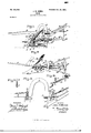
- Figure 1 is a side elevation of the improved plow.
- Fig. 2 is a plan view of the same.
- Fig. 3 is an enlarged side elevation of one portion of the plow-beam and the supports for the same.
- Fig. 4 4 is a vertical section through the tion; and
- Fig. 5 is a detail lperspective view of parts hereinafter more particularly described.
- the beam A may be made of any material. Usually, however, metal is employed, and at or near the center the beam A is providedwith an upwardly-arched section 10, and the rear end 11 of the beam is given more or less of an upward inclination, as is best shown in Fig. 1.
- a thumb-latch 12 is mounted upon the rear end portion of the beam, said thumblatch being spring-controlled, and the forward end of this thumb-latch extends down through an opening at the rear of the arched section 10 of the beam to an engagement with'teeth l seria Ne. 24,635. on meaei.)
- this forward standard 1S serves as a pivotsupport for the beam A, and to that end a piu 19, provided with a .head at its lower end and with a suitable nut atits upper end, is passed loosely through the beam and likewisethrough a suitable bearing made inthe upper portion of said standard 18, adjacent to which bearing anr opening is produced,-as shown in Figi 3, in order that the head of the bolt may be placed at the top of the beam, if desired, and'the nut introduced at said opening, said opening also enabling the bolt to be placed in the positionV shown in Fig. 3.
- the beam A has guided movement upon the plate 14, which serves as a table, and to that end a bolt 2O is passed through the beam at the rear of its arched section 10 and through the curved slot 15 in the plate or table 14.
- the upper end of this bolt is provided with a suitable nut 21, and the lower end of said bolt is'carried indirection of the rear of the beam, and on the arm thus formed a friction-roller2l is mounted, adapted-to engage with the under face of the plate or table 14, as isI especially shown in Fig. 3.
- the beam A is further guided by placing a friction-roller 22 in a recess 22a made in the lower edge of the beam over the table or platform 14, as isshown in Figs.
- the bolt 20 is preferably square where it passes through the beam, so that the bolt will not turn.
- both rollers will be in practically the same adjust- TOO ment.
- the handles 23 of the plow are at.- tachedto the rear standard 16, so that should the beam be carried to the right or to the left said handles 23 do not sustain undue strain, since they arein no manner connected with the beam.
- Boxes 24 are formed upon the standards 16 and 18, and in these boxes a shaft 25 is journaled.
- rlhis shaft 25 is usually made'tubular inthe interest of lightness and extends forward beyond the standard 18 and rearward beyond the standard 16 to a point below the handles 23.
- the shaft is preferably provided with a socket 26 at its rearend,and an anglelever 27 is pivoted at the junction of its members i/n said socket, so that the handles may be rocked verticallyand so that said handles when operated laterally will turn the shaft 25 to the right or to the left.
- a guide 28, attached to the handles 23 and extending below them, is utilized to direct the movement of the main member of the lever 27, and the ends of this guide extend forward parallel with the outer faces of the handles 23.
- the lever 27, in addition to its function of turning the shaft 25, is likewise intended to op ⁇ erate a locking device for the shares and moldboards, to be hereinafter described, and to this end a slotted bar 29 is held to slide on the standards 16 and 18 at a point above the landside'17, and at the forward end of this bar an angle-arm 30 is formed, the horizontal member of which is adaptedto pass through a U-shaped projection 31, formedV upon the upper edge of the landside near the front.
- the slotted bar 29 is provided with guides upon the front standard 18, and said bar is open at the front except that portion of the arm 30 which enters the projection 31, so as to free itself of dirt.
- an upward extension 32 is formed, adapted to slide on the shaft 25, and a spring 33 engages with the rear edge of the extension 32 and has bearing against a collar 34.
- the spring 33 is compressed, and this movement of the slotted bar 29 is accomplished by connecting the ends of a link 35 with the upper portion of the bar extension 32 and the forward member of the lever 27, as is best shown in Fig. 1.
- the arm 30 of the slotted bar 29 will be disengaged from the U projection 31 of the landside and the lever may be moved later ally, so as to turn the shaft 25 at the same time.
- the lever 27 reaches an end of the guide 28, the. lever will be no longer held by the guide 2S, and the spring 33 will act to carry the slotted bar 29 forward and cause the arm 30 to be brought again in locking engagement with the landside.
- the shares and moldboards are each two in number, and the shares 36 are attached to 'portion of each point.
- each moldboard At the under face of each moldboard an eye 40 is formed, and these eyes are so placed that when the mold board by turning the shaft 25 is brought down to an engagement with the ground and in engagement with the landside 17 the eye of that moldboard will enter the space between the members of the U projection 31 from the landside, so that. the arm 30 in passing through said projection 31 will likewise pass through the eye 40, and thus hold one of the moldboards and attached share in working position.
- an in terlockiug connection is formed between the point of the share and the landside, made by producing a Spur 41 on the forward end of the landside adapted to enter a recess 42, one of said recesses being made at the landside
- the landside 17 is preferably made hollow and tubular, as shown in Fig. L1, in order that it may be as light as possible; but its ends may be closed, if desired.
- the beam may be directed at its forward end to the right orto the left without interfering with the position of the supports for the beam and the position of the moldboards and shares. It is evident that by moving the lever 27 to the right or to the left either one o1' the other of the combined moldboards and shares may be brought to the ground, and when one moldboard and share are in working position the opposing moldboard and share will beheld out of the ground.
- the arch 10 in the beam A permits the use of a very large size of moldboard, as shown in Fig. 1.' If a still larger size of moldboard. is required, a larger arch 10 may be substituted for the one shown.
- the combination with standards arranged for connection with a beam and a landside secured at the lower ends of the standards, of a shaft mounted to revolve in said standards above the landside, extending beyond the front and rear portions of the standards, handles attached to the rear standard, a lever pivoted to the rear end of the shaft, a guide with which the lever is oonnected, a slotted projection formed upon the upper surface of the landside near its ⁇ forward end, a locking device consisting of a slotted bar having sliding movement on the standards and an arm which passes through the slotted projection from the landside, an extension from the rear of the bar, held to slide on the shaft, a spring mounted on the shaft and acting to force the slotted bar forward, and a connection between the extension fro'm the slotted bar and the lever pivoted on the shaft, combined plowshares and moldboards located one at each side of the shaft, straps connecting the moldboards, which straps are secured at their centers to the shaft, and eyes carried by the moldboards,
- locking device for the purpose set 'slot therein and teeth at its rear edge, of a beam pivoted upon thel forward standard, a roller engaging with the under surface of the table, a support for the said roller, adjustably attached to the beam and passed through the guide-slot ink the table, a second roller carried by the beam and. arranged for engagement with the upper surface of said table, and a thumb-latch located at the rear end portion of the beam, the forward end of which latch is adapted to engage with the toothed surface of said table, for the purpose specified.
Description
Patented 00h23, |9700..v
m. s vl E Hw. N mh w M.. n VW A Ww, .MY /B m J m w, n m M M m Y w w HLM m .-P m N .m m .J .w w1 ...nw 3 M, a 46 .s ...D M I o N h `landside, illustrating its tubular construc- `and pointed out in the claims.
UNiTED STATES' PATENT OFFICE.
JOHN N. HANNA, OF DEL NORTE, COLORADO.
PLOW.
srnoImcA'rIoN ferming pea of Lettere Patent Ne. 660,430, dated october 23, 1900.`
Application tied July 24, 1900.`
T0 all whom it may concern: A
Be it known that I, JOHN N. HANNA, a citizen of the United States, and a resident of Del Norte, in the county of Rio Grande and State of Colorado, have invented a new and Improved Plow, of which the following is a full, clear, and exact description.
The invention relates to that class of plows provided with two shares and moldboards located at opposite sides of the beam and means for bringing either share and its moldboard in operative connection with a common land# side.
The purpose of the invention is to simplify the construction of such plows and to provide an adjustable beam so arranged that but little strain will be sustained by the handles and to so shape the beam that large or smallV sized moldboardsrnay be employed, together with a turning and locking device for the shares and their moldboards, which turning and locking device islocated Within con venient reach from the handles.
The invention consists in the novel construction -and combination of theV several parts, as will be hereinafter fully set forth,
Reference is to be had to the accompanying drawings, forming a part of this specification, in which similar charactersof reference indicate corresponding parts in all the figures.
Figure 1 is a side elevation of the improved plow. Fig. 2 is a plan view of the same. Fig. 3 is an enlarged side elevation of one portion of the plow-beam and the supports for the same. Fig. 4 4is a vertical section through the tion; and Fig. 5 is a detail lperspective view of parts hereinafter more particularly described. I
The beam A may be made of any material. Usually, however, metal is employed, and at or near the center the beam A is providedwith an upwardly-arched section 10, and the rear end 11 of the beam is given more or less of an upward inclination, as is best shown in Fig. 1. A thumb-latch 12 is mounted upon the rear end portion of the beam, said thumblatch being spring-controlled, and the forward end of this thumb-latch extends down through an opening at the rear of the arched section 10 of the beam to an engagement with'teeth l seria Ne. 24,635. on meaei.)
'13, formed in the rear edge of a horizontaly plate 14, in which plate a'curved longitudinal slot 15 is produced for the purpose of guiding the plow-beam, which beam is pivoted on supports to be hereinafter described. r[he plate section 10'0f the beam a second standard- 18 is located, the forward Yend whereof is also attached to the landside 17. The upper portion of this forward standard 1S serves as a pivotsupport for the beam A, and to that end a piu 19, provided with a .head at its lower end and with a suitable nut atits upper end, is passed loosely through the beam and likewisethrough a suitable bearing made inthe upper portion of said standard 18, adjacent to which bearing anr opening is produced,-as shown in Figi 3, in order that the head of the bolt may be placed at the top of the beam, if desired, and'the nut introduced at said opening, said opening also enabling the bolt to be placed in the positionV shown in Fig. 3. l The beam A has guided movement upon the plate 14, which serves as a table, and to that end a bolt 2O is passed through the beam at the rear of its arched section 10 and through the curved slot 15 in the plate or table 14. The upper end of this bolt is provided with a suitable nut 21, and the lower end of said bolt is'carried indirection of the rear of the beam, and on the arm thus formed a friction-roller2l is mounted, adapted-to engage with the under face of the plate or table 14, as isI especially shown in Fig. 3. The beam A is further guided by placing a friction-roller 22 in a recess 22a made in the lower edge of the beam over the table or platform 14, as isshown in Figs. 1 andj3, the trunnions of theY upper friction-roller 22 being journaled in uthe side walls of the recess 221, and this upper roller 22 travels upon the upper face of the table 14. The bolt 20 is preferably square where it passes through the beam, so that the bolt will not turn.
It will be observed that by adjusting the bolt 20, carrying the lower roller 21a, both rollers will be in practically the same adjust- TOO ment. The handles 23 of the plow are at.- tachedto the rear standard 16, so that should the beam be carried to the right or to the left said handles 23 do not sustain undue strain, since they arein no manner connected with the beam.
.At the rear end of the slotted bar 29 an upward extension 32 is formed, adapted to slide on the shaft 25, and a spring 33 engages with the rear edge of the extension 32 and has bearing against a collar 34. When the slotted bar 29 is drawn rearward to disengage the arm 30 from the U-shaped projection 31 on the landside, the spring 33 is compressed, and this movement of the slotted bar 29 is accomplished by connecting the ends of a link 35 with the upper portion of the bar extension 32 and the forward member of the lever 27, as is best shown in Fig. 1. When the main portion of the lever 27 is carried along the main or rear surface of the guide 28, the arm 30 of the slotted bar 29 will be disengaged from the U projection 31 of the landside and the lever may be moved later ally, so as to turn the shaft 25 at the same time. When, however, the lever 27 reaches an end of the guide 28, the. lever will be no longer held by the guide 2S, and the spring 33 will act to carry the slotted bar 29 forward and cause the arm 30 to be brought again in locking engagement with the landside.
The shares and moldboards are each two in number, and the shares 36 are attached to 'portion of each point.
These combined shares and moldhoards are placed withthe inner edges of the shares and moldboards facing each other, and the opposing moldboards are connected near the front by a short strap 37 and near the rear by a longer strap 38. At the central portion of these straps 37 and 38 eyes 39 are formed, through which the shaft 25 passes, the eyes being secured to said straps in any approved manner. When the moldboards and shares are so attached, nthe forward eye 39 will be in front of the forward standard 18 and the rear eye between the two standardsl and 18.
At the under face of each moldboard an eye 40 is formed, and these eyes are so placed that when the mold board by turning the shaft 25 is brought down to an engagement with the ground and in engagement with the landside 17 the eye of that moldboard will enter the space between the members of the U projection 31 from the landside, so that. the arm 30 in passing through said projection 31 will likewise pass through the eye 40, and thus hold one of the moldboards and attached share in working position. Preferably an in terlockiug connection is formed between the point of the share and the landside, made by producing a Spur 41 on the forward end of the landside adapted to enter a recess 42, one of said recesses being made at the landside The landside 17 is preferably made hollow and tubular, as shown in Fig. L1, in order that it may be as light as possible; but its ends may be closed, if desired.
In operation the beam may be directed at its forward end to the right orto the left without interfering with the position of the supports for the beam and the position of the moldboards and shares. It is evident that by moving the lever 27 to the right or to the left either one o1' the other of the combined moldboards and shares may be brought to the ground, and when one moldboard and share are in working position the opposing moldboard and share will beheld out of the ground. The arch 10 in the beam A permits the use of a very large size of moldboard, as shown in Fig. 1.' If a still larger size of moldboard. is required, a larger arch 10 may be substituted for the one shown.
Having thus described my invention, I claim as new and desire to secure by Letters Patent- 1. In a plow, the combination, with standards arranged for connection with a beam and a landside secured to the lower ends of the standards, of a shaft mounted to revolve upon the standards above the landside, extending forward and rearward from the standards, two combined plowshares and moldboards, straps connecting the moldboards, which straps are secured at their centers to said shaft, a locking device arranged to lock the lnoldboards to the landside, and a lever con nected with the shaft, which lever is likewise IOO IIO
connected with the locking device and serves to operate both, as described.
2. In a plow, the combination, with standards arranged for connection with a beam and a landside secured at the lower ends of the standards, of a shaft mounted to revolve in said standards above the landside, extending beyond the front and rear portions of the standards, handles attached to the rear standard, a lever pivoted to the rear end of the shaft, a guide with which the lever is oonnected, a slotted projection formed upon the upper surface of the landside near its` forward end, a locking device consisting of a slotted bar having sliding movement on the standards and an arm which passes through the slotted projection from the landside, an extension from the rear of the bar, held to slide on the shaft, a spring mounted on the shaft and acting to force the slotted bar forward, and a connection between the extension fro'm the slotted bar and the lever pivoted on the shaft, combined plowshares and moldboards located one at each side of the shaft, straps connecting the moldboards, which straps are secured at their centers to the shaft, and eyes carried by the moldboards, adapted to enter the space between the members of the slotted projection on the iandside i and receive the arm carried by the slotted bar of the. locking device, for the purpose set 'slot therein and teeth at its rear edge, of a beam pivoted upon thel forward standard, a roller engaging with the under surface of the table, a support for the said roller, adjustably attached to the beam and passed through the guide-slot ink the table, a second roller carried by the beam and. arranged for engagement with the upper surface of said table, and a thumb-latch located at the rear end portion of the beam, the forward end of which latch is adapted to engage with the toothed surface of said table, for the purpose specified.
In testimony whereof I have signed my name to this specification in the presence of two subscribing witnesses.
JOHN N. I-IANNA. Witnesses:
HENRY HANNA, WILBER E. SHAW.
Priority Applications (1)
| Application Number | Priority Date | Filing Date | Title |
|---|---|---|---|
| US2463500A US660430A (en) | 1900-07-24 | 1900-07-24 | Plow. |
Applications Claiming Priority (1)
| Application Number | Priority Date | Filing Date | Title |
|---|---|---|---|
| US2463500A US660430A (en) | 1900-07-24 | 1900-07-24 | Plow. |
Publications (1)
| Publication Number | Publication Date |
|---|---|
| US660430A true US660430A (en) | 1900-10-23 |
Family
ID=2728994
Family Applications (1)
| Application Number | Title | Priority Date | Filing Date |
|---|---|---|---|
| US2463500A Expired - Lifetime US660430A (en) | 1900-07-24 | 1900-07-24 | Plow. |
Country Status (1)
| Country | Link |
|---|---|
| US (1) | US660430A (en) |
-
1900
- 1900-07-24 US US2463500A patent/US660430A/en not_active Expired - Lifetime
Similar Documents
| Publication | Publication Date | Title |
|---|---|---|
| US660430A (en) | Plow. | |
| US199036A (en) | Improvement in reversible plows | |
| US712031A (en) | Wheel-adjusting device for plows. | |
| US372206A (en) | Cultivator | |
| US1062246A (en) | Subsoil-disk. | |
| US1062374A (en) | Cultivator. | |
| US484128A (en) | Side-hill plow | |
| US210176A (en) | Improvement in plows | |
| US199558A (en) | Improvement in plows | |
| US540344A (en) | Landside-plow | |
| US225452A (en) | woodbuey | |
| US156123A (en) | Improvement in plows | |
| US396859A (en) | Clevis | |
| US1100503A (en) | Gang-plow. | |
| US237772A (en) | Assigxoe to a | |
| US1222898A (en) | Plow. | |
| US1187488A (en) | Attachment for gang-plows and the like. | |
| US225134A (en) | Swivel-plow and colter | |
| US628573A (en) | Plow. | |
| US911848A (en) | Adjustable handle. | |
| US177503A (en) | Improvement in plows | |
| US254585A (en) | andeeson | |
| US346879A (en) | Geoege wiaed | |
| US1030700A (en) | Harrow attachment for plows. | |
| US568279A (en) | Albert c |