US6580923B1 - Portable telephone set - Google Patents
Portable telephone set Download PDFInfo
- Publication number
- US6580923B1 US6580923B1 US09/518,827 US51882700A US6580923B1 US 6580923 B1 US6580923 B1 US 6580923B1 US 51882700 A US51882700 A US 51882700A US 6580923 B1 US6580923 B1 US 6580923B1
- Authority
- US
- United States
- Prior art keywords
- card
- portable telephone
- telephone set
- card holder
- housing
- Prior art date
- Legal status (The legal status is an assumption and is not a legal conclusion. Google has not performed a legal analysis and makes no representation as to the accuracy of the status listed.)
- Expired - Lifetime
Links
Images


Classifications
-
- H—ELECTRICITY
- H04—ELECTRIC COMMUNICATION TECHNIQUE
- H04B—TRANSMISSION
- H04B1/00—Details of transmission systems, not covered by a single one of groups H04B3/00 - H04B13/00; Details of transmission systems not characterised by the medium used for transmission
- H04B1/38—Transceivers, i.e. devices in which transmitter and receiver form a structural unit and in which at least one part is used for functions of transmitting and receiving
- H04B1/3816—Mechanical arrangements for accommodating identification devices, e.g. cards or chips; with connectors for programming identification devices
- H04B1/3818—Arrangements for facilitating insertion or removal of identification devices
-
- G—PHYSICS
- G06—COMPUTING; CALCULATING OR COUNTING
- G06K—GRAPHICAL DATA READING; PRESENTATION OF DATA; RECORD CARRIERS; HANDLING RECORD CARRIERS
- G06K13/00—Conveying record carriers from one station to another, e.g. from stack to punching mechanism
- G06K13/02—Conveying record carriers from one station to another, e.g. from stack to punching mechanism the record carrier having longitudinal dimension comparable with transverse dimension, e.g. punched card
- G06K13/08—Feeding or discharging cards
- G06K13/0806—Feeding or discharging cards using an arrangement for ejection of an inserted card
- G06K13/0812—Feeding or discharging cards using an arrangement for ejection of an inserted card the ejection arrangement utilizing a push bar for manipulation by hand in order to eject the inserted card
-
- G—PHYSICS
- G06—COMPUTING; CALCULATING OR COUNTING
- G06K—GRAPHICAL DATA READING; PRESENTATION OF DATA; RECORD CARRIERS; HANDLING RECORD CARRIERS
- G06K7/00—Methods or arrangements for sensing record carriers, e.g. for reading patterns
- G06K7/0013—Methods or arrangements for sensing record carriers, e.g. for reading patterns by galvanic contacts, e.g. card connectors for ISO-7816 compliant smart cards or memory cards, e.g. SD card readers
- G06K7/0056—Methods or arrangements for sensing record carriers, e.g. for reading patterns by galvanic contacts, e.g. card connectors for ISO-7816 compliant smart cards or memory cards, e.g. SD card readers housing of the card connector
- G06K7/0069—Methods or arrangements for sensing record carriers, e.g. for reading patterns by galvanic contacts, e.g. card connectors for ISO-7816 compliant smart cards or memory cards, e.g. SD card readers housing of the card connector including means for detecting correct insertion of the card, e.g. end detection switches notifying that the card has been inserted completely and correctly
-
- H—ELECTRICITY
- H04—ELECTRIC COMMUNICATION TECHNIQUE
- H04B—TRANSMISSION
- H04B1/00—Details of transmission systems, not covered by a single one of groups H04B3/00 - H04B13/00; Details of transmission systems not characterised by the medium used for transmission
- H04B1/38—Transceivers, i.e. devices in which transmitter and receiver form a structural unit and in which at least one part is used for functions of transmitting and receiving
- H04B1/3827—Portable transceivers
- H04B1/3883—Arrangements for mounting batteries or battery chargers
-
- H—ELECTRICITY
- H04—ELECTRIC COMMUNICATION TECHNIQUE
- H04M—TELEPHONIC COMMUNICATION
- H04M1/00—Substation equipment, e.g. for use by subscribers
- H04M1/02—Constructional features of telephone sets
- H04M1/0202—Portable telephone sets, e.g. cordless phones, mobile phones or bar type handsets
- H04M1/026—Details of the structure or mounting of specific components
- H04M1/0262—Details of the structure or mounting of specific components for a battery compartment
-
- H—ELECTRICITY
- H04—ELECTRIC COMMUNICATION TECHNIQUE
- H04M—TELEPHONIC COMMUNICATION
- H04M2250/00—Details of telephonic subscriber devices
- H04M2250/14—Details of telephonic subscriber devices including a card reading device
Definitions
- the present invention relates to portable telephone sets, and more particularly to a portable telephone set suitable for a global system for mobile communication (GSM).
- GSM global system for mobile communication
- the GSM does not require registration of a telephone number for each portable telephone set.
- Each individual (subscriber) is assigned to a subscriber identity module in which information concerning the subscriber is stored. If the subscriber exchanges the old portable telephone set by a new one, the subscriber identity module is detached from the old telephone set and is then inserted into the new one. If the rent portable telephone set is used, the subscriber inserts the own subscriber identity module into the set. Thus, the new or rent portable telephone set can be used as the subscriber own portable telephone set.
- the subscriber identity module is realized by a compact subscriber identity card in which an integrated circuit including a memory is built.
- a compact subscriber identity card in which an integrated circuit including a memory is built.
- Such a card has a size of, for instance, 25 mm ⁇ 15 mm.
- the portable telephone set has been required to be thin and have a structure which enables the subscriber identity card to be easily detached therefrom.
- Such a card stores information important to the subscriber, such as subscriber identity information and accounting information. It is not desired to easily detach, from the portable telephone set, the information cards suitable for the portable telephone set as described above in terms of privacy protection.
- the portable telephone set is required to satisfy the above.
- the cards to be attached to the portable telephone sets are referred to as portable telephone information cards.
- the portable telephone information cards include the above subscriber identity card, and another card which stores information other than the subscriber identity information.
- FIGS. 1A and 1B are diagrams of a portable telephone set 10 for the GSM disclosed in Japanese Laid-Open Patent Application No. 8-265404.
- a battery pack 11 can be attached to the back surface of the portable telephone set 10 .
- a card loading mechanism 12 is provided in a bottom surface portion of a battery pack mount portion 13 provided to the back surface of the portable telephone set 10 , that is, the back surface of the mounted battery pack 11 .
- the battery pack mount portion 13 has a bottom plate 14 , in which a rectangular opening 15 is formed.
- the subscriber identity card loading mechanism 12 is mainly composed of a housing 20 and a holder 21 .
- the housing 20 is fixed to the inside of the portable telephone set 10 , and faces the opening 15 .
- the holder 21 is joined to the housing by a hinge.
- a subscriber identity card 22 can be mounted as follows. The holder 21 is rotated and set upright. Then, the subscriber identity card 22 is inserted into the holder 21 , which is then depressed and rotated. Thus, the card 22 passes through the opening 15 and is engaged with the housing 20 .
- a subscriber identity card 22 can be taken out by the reverse operation. It should be noted that the subscriber identity card 22 which is mounted cannot be taken out unless the battery pack 11 is taken out.
- the above portable telephone set 10 has the following problems.
- the battery pack mount portion 13 located in the back surface of the portable telephone set 10 includes a slight recess.
- a circuit board, a tenkey and other components are tightly provided in a portion 16 opposite to the battery pack mount portion 13 .
- the card loading mechanism 12 is provided in the above portion 16 , and thus has an increased thickness t 1 .
- the thickness t 3 of the portable telephone set 10 is equal to the sum of the thickness t 2 necessary to provide the circuit board, the tenkey and other components and the thickness t 1 of the card loading mechanism 12 .
- the thickness t 3 prevents down-sizing of the portable telephone set 10 .
- the holder 21 cannot be detached from the housing 20 . Hence, it is necessary to take the portable telephone 10 by hand in order to take out the subscriber identity card 22 from the holder 21 and insert the subscriber identity card 22 into the holder 21 . The above is troublesome. Further, the card loading mechanism 12 has a complex structure.
- a detection switch detects the holder 21 even when the holder 21 having no card is mounted. Hence, if the subscriber dials with no card inserted into the holder 21 , the portable telephone set 10 starts a corresponding calling procedure although it is not completed.
- a more specific object of the present invention is to provide a compact portable telephone set having a simplified card loading mechanism.
- a portable telephone set comprising: a case having first and second sides opposite to each other; a group of keys located on the first side of the case; and a card loading mechanism.
- the case includes first and second portions located on the second side. The first portion can accommodate a battery pack, and the second portion is next to the first portion and accommodates the card loading mechanism. A card in which information is stored can be loaded to the card loading mechanism.
- the card loading mechanism and the battery pack can be arranged side by side, so that the thickness of the portable telephone set can be reduced.
- the above portable telephone set may be configured so that: the case has a wall interposed between the first and second portions; and the wall has an opening through which the card can be inserted into the second portion and loaded to the card loading mechanism. Hence, the card cannot be detached unless the battery pack is detached. Thus, it is possible to prevent the card from happening to be detached from the portable telephone set.
- the portable telephone set may be configured so that the second portion includes a protrusion with respect to a bottom portion of the first portion.
- a protrusion means that there is a comparatively large spatial area in the portable telephone set.
- the card loading mechanism can be provided in the second portion without a particular difficulty.
- the portable telephone set may be configured so that the card loading mechanism comprises: a housing located in the second portion; and a card holder having a card accommodating portion in which the card can be accommodated, the card holder having a spring portion which portion has a handle portion with which a finger can be engaged, and an engagement craw which can engage with a part of the housing when the card holder is inserted into the housing.
- the card loading mechanism comprises: a housing located in the second portion; and a card holder having a card accommodating portion in which the card can be accommodated, the card holder having a spring portion which portion has a handle portion with which a finger can be engaged, and an engagement craw which can engage with a part of the housing when the card holder is inserted into the housing.
- the portable telephone set may be configured so that the spring portion is formed of a resin.
- the spring portion having a resilient property can be realized with ease.
- the portable telephone set may be configured so that: the spring portion is formed of a resin and can be resiliently bent in a thickness direction of the portable telephone set; and the handle portion is located in a free end of the spring portion.
- the card holder can easily be drawn by a single-finger operation.
- the portable telephone set may be configured so that: the spring portion is formed of a resin and can be resiliently bent in a thickness direction of the portable telephone set; the handle portion is located in a free end of the spring portion; and the card holder has another handle portion located opposite to the handle portion.
- the card holder can easily be drawn by using two fingers such as the thumb finger and the forefinger.
- the portable telephone set may be configured so that: the card holder has a card holding portion having a spring property and projecting from a side of the card accommodating portion; and the card holding portion engages with a part of the card so that the card can be restricted in the second portion.
- the card holding portion of the card holder can certainly hold the card.
- the portable telephone set may be configured so that the card loading mechanism comprises: a housing located in the second portion; a card holder having a card accommodating portion in which the card can be accommodated; and a detection switch which detects a situation in which the card holder with the card loaded thereto is inserted into the housing.
- the card loading mechanism comprises: a housing located in the second portion; a card holder having a card accommodating portion in which the card can be accommodated; and a detection switch which detects a situation in which the card holder with the card loaded thereto is inserted into the housing.
- the portable telephone set may be configured so that the detection switch has a terminal having a spring property, the terminal which can be engaged with the card accommodated in the card holder.
- the portable telephone set may be configured so that the card holder has a spring portion which portion has a handle portion with which a finger can be engaged, and an engagement craw which can engage with a part of the housing when the card holder is inserted into the housing.
- the card holding portion of the card holder can certainly hold the card.
- the portable telephone set may be configured so that the card loading mechanism can receive the card in a state in which the battery pack is detached from the first portion. Hence, the card can be prevented from being drawn in the state in which the battery pack is attached to the portable telephone set.
- FIGS. 1A and 1B are diagrams of a conventional portable telephone set
- FIG. 2A is a partially-cutout plan view of a portable telephone set according to an embodiment of the present invention.
- FIG. 2B is a cross-sectional view of the portable telephone set shown in FIG. 2A;
- FIG. 3 is an exploded perspective view of the portable telephone set shown in FIGS. 2A and 2B;
- FIG. 4 is an enlarged perspective view taken along an arrow III shown in FIG. 2B;
- FIG. 5 is a perspective view of a subscriber identity card loading mechanism of the portable telephone set
- FIG. 6 is a perspective view of a card holder of the portable telephone set
- FIGS. 7A, 7 B, 7 C, 7 D and 7 E are diagrams of the subscriber identity card holding mechanism to which a card is loaded;
- FIGS. 8A and 8B are diagrams of a detection switch built in the portable telephone set
- FIG. 9 is an enlarged perspective view showing an operation of drawing the card holder from the portable telephone set.
- FIG. 10 is an enlarged perspective view showing an operation of loading the card holder
- FIGS. 11A, 11 B and 11 C show another subscriber identity loading mechanism
- FIG. 12 is an enlarged perspective view of a state in which the subscriber identity card loading mechanism is installed in the portable telephone set;
- FIGS. 13A and 13B are diagrams of a card holder
- FIGS. 14A, 14 B and 14 C are diagrams of a housing
- FIGS. 15A, 15 B and 15 C are diagrams of another detection switch.
- FIGS. 2A and 2B are diagrams of a portable telephone set 30 which can be applied to the GSM according to an embodiment of the present invention. Further, FIG. 3 is an exploded perspective view of the portable telephone set 30 . FIG. 4 is an enlarged perspective view taken along arrow III shown in FIG. 2 B.
- the portable telephone set 30 has a front case 32 and a back case 34 between which a printed wiring board unit 36 is interposed.
- the whole case of the portable telephone set 30 includes the cases 32 and 34 .
- the front case 32 is equipped with a key group sheet 31 on which a plurality of keys are arranged.
- the back case 34 is equipped with an antenna 37 .
- the printed wiring board unit 36 is equipped with a liquid crystal unit 35 .
- the front case 32 , the rear case and the printed wiring board unit 36 are longitudinal in directions Y 1 and Y 2 .
- a housing 51 which will be described in detail later, is attached to the printed wiring board unit 36 .
- the portable telephone set 30 has a front surface facing in a direction Z 2 , and a back surface facing in a direction Z 1 .
- a plurality of keys 39 are arranged in a front surface 30 a of the portable telephone set 30 so that the keys 39 occupy an area located in a direction Y 2 with respect to the center in the longitudinal direction.
- a display window 40 of the liquid crystal unit 35 and an acoustic output part 41 formed of a speaker are provided in an area located in a direction Y 1 with respect to the keys 39 .
- An acoustic input part 42 formed of a microphone is provided in the area located in the direction Y 2 with respect to the key 39 .
- a battery pack mounting portion 45 is provided to the back surface 30 b of the portable telephone set 30 and is located in the area extending in the direction Y 2 from the center in the longitudinal direction. In other words, the battery pack mounting portion 45 is located in the portion corresponding to the arrangement of the keys 39 .
- a battery pack 46 having a length approximately equal to half the length of the portable telephone set 30 is mounted on the battery pack mounting portion 45 .
- the battery pack mounting portion 45 has a recess which causes the back surface 30 b of the portable telephone set 30 with the battery pack 46 mounted to be a flat surface.
- a portion 47 which is adjacent to the battery pack mounting portion 45 in the longitudinal direction and totally occupies the whole located in the direction Y 1 with respect to the battery pack mounting portion 45 , has a projection projecting from a bottom surface 45 a in the direction Z 1 .
- the portion 47 will be referred to as a battery pack mount adjacent portion
- the interface between the battery pack mounting portion 45 and the battery pack adjacent portion 47 is a vertical wall 45 b which stands upright in the direction Z 1 from the bottom surface 45 a .
- a card holder inserting opening 45 - b is formed in a lower end portion of the vertical wall 45 b .
- the lower side of the vertical wall 45 b corresponds to the position in which the card holder insertion opening 45 - b is formed.
- the card holder 52 when the card holder 52 is placed on the bottom surface 45 a of the battery pack mounting portion 45 of the portable telephone set 30 , the card holder 52 faces the card holder insertion opening 45 - b.
- the portable telephone set 30 has a subscriber identity card loading mechanism 50 , which is provided in an inner space 47 a of the battery pack mount adjacent portion 47 .
- the mechanism 50 is built in the portable telephone set 30 without any increase in the thickness thereof because the battery pack mount adjacent portion 47 projects from the bottom surface 45 a of the battery pack mounting portion 45 , and is located in the area which has a larger spatial margin than the other area of the portable telephone set 30 . Further, the size of the card loading mechanism 50 itself is small.
- the thickness of the portable telephone set 30 which is denoted as t 10 , is equal to that obtained when the card loading mechanism 50 is not installed.
- the card loading mechanism 50 includes the housing 51 and the card holder 52 which holds the subscriber identity card 22 and is attached to the housing 51 .
- the card loading mechanism 50 has an upper surface facing in the direction Z 1 , a lower surface in the direction Z 2 , a front surface in the direction Y 2 , and a rear portion in the direction Y 1 .
- the width of the mechanism 50 extends in the directions X 1 and X 2 .
- the subscriber identity card 22 includes a built-in integrated circuit 22 a and six electrodes 22 b provided to the lower surface of the card 22 . Further, the subscriber identity card 22 has a chamfered corder 22 c.
- the card holder 52 is a synthetic resin molded component, and has a flat shape which is long in the directions Y 1 and Y 2 .
- the card holder 52 includes a subscriber identity card accommodating portion 52 a provided to the lower surface side, a front panel portion 52 b , and a cantilever plate spring 52 c provided to the upper surface side. Further, the card holder 52 has rail portions 52 d and 52 e which are provided to ends thereof located in the directions X 1 and X 2 and extend in the directions Y 1 and Y 2 .
- the subscriber identity card accommodating portion 52 a has a size which corresponds to the subscriber identity card 22 , and a depth “a” corresponding to the thickness t 20 of the card 22 so that the card accommodating portion 52 a has a flat recess shape into which the subscriber identity card can be accommodated.
- the card accommodating portion 52 a includes a slant portion 52 a - 1 , which corresponds to the chamfered corner 22 c .
- Two plate springs 52 a - 2 and 52 a - 3 made of synthetic resin are provided to the end X 2 of the card accommodating portion 52 a so that the free ends thereof face each other and are arranged in a line in the directions Y 1 and Y 2 .
- the plate springs 52 a - 2 and 52 a - 3 can be resiliently bent in the direction X 2 .
- the plate springs 52 a - 2 and 52 a - 3 function as subscriber identity card holding portions having a spring property.
- holes 52 a - 4 and 52 - 5 for pushing out the subscriber identity card are formed in the vicinity of the ends of the bottom of the card accommodating portion 52 a in the direction Y 1 .
- the front panel portion 52 b has a U-shaped cutout portion 52 b - 1 located at the center thereof. Protrusions 52 b - 2 and 52 b - 3 which protrude in the direction Z 1 are provided on both sides of the U-shaped cutout portion 52 b - 1 .
- the U-shaped cutout portion 52 b - 1 functions to accommodate a handle portion 52 c - 3 which will be described in detail later.
- the protrusions 52 b - 2 and 52 b - 3 come into contact with a counter U-shaped frame portion 51 a - 4 a which will also be described later.
- the cantilever plate spring 52 c is integrally formed when molding the card holder 52 , and is formed so that a portion of the upper surface of the card holder 52 in the width direction (in the directions X 1 and X 2 ) is cut and raised.
- the plate spring 52 c has a width W 1 that is approximately equal to 1 ⁇ 4 of the width W 2 of the card holder 52 .
- the plate spring 52 c has a root portion 52 c - 1 located in the center of the card holder 52 in the directions Y 1 and Y 2 .
- the root portion 52 c - 1 stands upright by a distance “b” so that the remaining portion of the plate spring 52 c horizontally extends to the front panel portion 52 b in the direction Y 2 .
- the cantilever plate spring 52 c has an engagement craw 52 c - 2 that is located in the center of the upper surface thereof and projects in the direction Z 1 . Further, the cantilever plate spring 52 c has the handle portion 52 c - 3 located at the end thereof.
- the engagement craw 52 c - 2 has a slant surface 52 c - 2 a in the direction Y 1 , and a vertical surface 52 c - 2 b in the direction Y 2 .
- the handle portion 52 c - 3 has a recess portion 52 c - 3 a on the upper surface oriented in the direction Y 1 .
- the recess portion 52 c - 3 a makes it possible for the end of the forefinger of the hand of the operator to be easily engaged with the handle 52 c - 3 . Further, the handle portion 52 c - 3 is located in the U-shaped cutout portion 52 b - 1 of the front panel portion 52 b.
- the cantilever plate spring 52 c When the handle portion 52 c - 3 is pushed in the direction Z 2 , the cantilever plate spring 52 c is bent and the engagement craw 52 c - 2 is thus displaced in the direction Z 2 .
- the cantilever plate spring 52 c is located over the upper surface of the card holder 52 by the distance “b”. Hence, even if the spring portion 52 c is bent, it is not entered into the subscriber identity card accommodating portion 52 a.
- the housing 51 includes a housing main body 51 a made of synthetic resin, a plurality of terminals 51 b fixed to the housing main body 51 a , and a detection switch 51 c provided to the housing main body 51 a .
- the housing 51 has a size greater than the card holder 52 .
- the housing main body 51 a includes a bottom, plate portion 51 a - 1 , sidewall portions 51 a - 2 and 51 a - 3 , and a counter U-shaped frame portion 51 a - 4 .
- the sidewall portions 51 a - 2 and 52 - 3 which are located on both the sides of the housing main body 51 a in the directions X 1 and X 2 and extend upwards in the direction Z 1 .
- the counter frame portion 51 a - 4 are located on both the sides in the direction Y 2 .
- Guide grooves 51 a - 5 and 51 - 6 are formed in the parts of the sidewall portions 51 a - 2 and 51 a - 3 which face the bottom plate portion 51 a - 1 .
- a guard holder accommodating portion 51 d is formed on the upper surface side of the bottom plate portion 51 a - 1 .
- the guard holder accommodating portion 51 d has a flat space partitioned by the sidewall portions 51 a - 2 and 51 a - 3 .
- the counter U-shaped frame portion 51 a - 4 forms an entrance 51 e to the card holder accommodating portion 51 d .
- Two bosses 51 a - 1 a and 51 a - 1 b for defining the attachment position of the housing 51 are formed on the lower surface of the bottom plate portion 51 a - 1 .
- the counter U-shaped frame portion 51 a - 4 includes a central counter U-shaped frame portion 51 a - 4 a , which is a step portion higher than the frame portion 51 a - 4 .
- the portion 51 a - 4 a is provided to allow the cantilever plate spring 52 c of the card holder 52 to pass therethrough.
- Two upright portions 51 a - 4 b and 51 a - 4 c located on both sides of the frame portion 51 a - 4 a receive the protrusions 52 b - 2 and 52 b - 3 when the card holder 52 is inserted.
- a cut portion 51 a - 4 e having a U shape corresponding to the size of the engagement craw 52 c - 2 is formed in an end of the frame portion 51 a - 4 a extending in the direction Y 1 .
- the frame portion 51 a - 4 d functions as an engagement portion with which the engagement craw 52 c - 2 is engaged.
- the six terminal members 51 b are fixed to the upper surface 51 a - 1 a of the bottom plate portion 51 a - 1 .
- Arc-shaped terminal portions 51 b - 1 are respectively provided on the ends of the six terminal members 51 b so as to correspond to the six electrodes 22 b of the subscriber identity card 22 .
- Terminal portions 51 b - 2 provided on the other ends of the six terminal members 51 b extend outwards from the ends in the directions Y 1 and Y 2 .
- the terminal portions 51 b - 2 have the same height as that of the lower surface 51 a - 1 b of the bottom plate portion 51 a - 1 .
- the detection switch 51 c has a first contact member 51 c - 1 and an L-shaped second contact member 51 c - 2 , and is normally closed.
- the first contact member 51 c - 1 and the second contact member 51 c - 2 are fixed to the lower surface 51 a - 1 b of the bottom plate portion 51 a - 1 .
- the first contact member 51 c - 1 has one end located in the direction Y 1 , which end is fixed, while the other end thereof can flexibly be bent.
- the first contact 51 c - 1 has a convex portion 51 c - 1 a protruding in the direction Z 1 .
- the convex portion 51 c - 1 a slightly protrudes from the upper surface 51 a - 1 a of the bottom plate portion 51 a - 1 via an opening window 51 a - 1 c of the bottom plate portion 51 a - 1 .
- the opening window 51 a - 1 c (the convex portion 51 c - 1 a ) is disposed in a position in which the opening window 51 a - 1 c is pushed by the subscriber identity card 22 held in the card holder 52 when the card holder 52 is inserted into the housing 51 .
- the first contact member 51 c - 1 is in contact with the second contact member 51 c - 2 , as shown in FIG. 8 A. Hence, the detection switch 51 c is maintained in the closed state.
- the printed wiring board unit 36 has a flexible printed circuit board used to attach the housing 51 thereto.
- the flexible printed circuit board 60 extending from the inside of the printed wiring board unit 36 is folded and adheres to the upper surface of the unit 36 .
- a plurality of lands 61 are provided to the flexible printed circuit board 60 so as to have an arrangement which corresponds to the terminal portions 51 b - 2 .
- Holes 62 are formed in the upper surface of the unit 36 and the board 60 so that the positions of the holes 62 correspond to those of the bosses 51 a - 1 a and 51 a - 1 b.
- the housing 51 is positioned so that the bosses 51 a - 1 a and 51 a - 1 b are engaged with the holes 62 .
- the terminal portions 51 b - 2 are soldered to the lands 61 .
- the housing 51 is mounted on the upper surface of the printed wiring board unit 36 so that the entrance 51 e is oriented along the direction Y 2 .
- the housing 51 can completely be accommodated in the battery pack mount adjacent portion 47 , and the entrance 51 e faces a card holder insertion opening 45 b - 1 of the vertical wall 45 b in the state in which the printed wiring board unit 36 is covered by the front case 32 and the back case 34 .
- a finger inserting recess portion 45 b - 2 is formed in the vertical wall 45 b in addition to the card holder insertion opening 45 b - 1 , which opening has a shape corresponding to the front panel portion 52 b of the card holder 52 .
- the finger inserting recess portion 45 b - 2 makes it easy for the forefinger of the operator to engage with the handle portion 52 c - 3 .
- the finger inserting recess portion 45 b - 2 is located just above the card holder insertion opening 45 b - 1 , and is recessed in the direction Y 1 so that the degree of recess is increased in the direction Z 2 .
- the above procedure is comprised of the following first to fifth steps.
- the first step is to detach the battery pack 46 from the portable telephone set 30 .
- the second step is to take out the card holder 52 having no card.
- the third step is to insert the own subscriber identity card 22 into the card holder 52 .
- the fourth step is to load the card holder 52 with the card 22 inserted therein to the housing 51 .
- the fifth step is to attach the battery pack 46 .
- the battery pack 46 is detached from the portable telephone set 30 . Hence, as shown in FIG. 4, the handle portion 52 c - 3 is exposed.
- the card holder 52 having no card is drawn and taken out.
- a forefinger 70 is inserted into the finger insertion recess portion 45 b - 2 .
- the handle portion 52 c - 3 is pressed in the direction Z 2 , and is thereafter drawn in the direction Y 2 as indicated as indicated by an arrow 72 .
- the cantilever plate spring 52 c is bent in the direction Z 2 , and the engagement craw 52 c - 2 is disengaged from the central counter U-shaped frame portion 51 a - 4 a .
- the card holder 52 is released from the locked state in which it is locked to the housing 51 .
- the forefinger 70 strongly engages with the recess portion 52 c - 3 a of the handle portion 52 c - 3 .
- the craw portion 52 c - 2 passes below the frame portion 51 a - 4 a , so that the card holder 52 is drawn to the outside of the housing 51 .
- the card holder 52 can be drawn by the operation of only the forefinger.
- the subscriber identity card 22 of the operator is inserted in the card holder 52 .
- the card 22 is lightly pushed in the subscriber identity card accommodating portion 52 a in the direction reverse to the direction shown in FIG. 6A so that the card accommodating portion 52 a faces up. hence, the plate springs 52 a - 2 and 52 a - 3 are resiliently bent, so that the card 22 is loaded to the card holder 52 .
- the card holder 52 is detached from the portable telephone set 30 .
- the card 22 can be correctly loaded to the card holder 52 due to the function of the chamfered portion 22 c of the card 22 and the slant portion 52 - 1 of the card accommodating portion 52 a .
- the card 22 is pushed in the single direction by the plate springs 52 a - 2 and 52 a - 3 . Hence, even when the card holder 52 is turned reversely so that the card accommodating portion 52 a faces down, the card 22 does not drop off.
- the card holder 52 is inserted into and loaded to the housing 51 .
- the card holder 52 is placed on the bottom surface 45 a of the battery pack loading portion 45 of the portable telephone set 30 so that the card holder 52 faces the card holder insertion opening 45 b - 1 . Then, the card holder 52 is made to slide in the direction Y 1 so that it passes through the card holder insertion opening 45 b - 1 . Hence, the card holder 52 is inserted into the housing 51 .
- the card holder 52 faces the card holder insertion opening 45 b - 1 .
- This arrangement facilitates the operation of orienting the card holder 52 toward the card holder insertion opening 45 b - 1 , so that the card holder 52 can easily be loaded to the housing 51 .
- the card holder 52 is guided and regulated in the directions X 1 , X 2 , Z 1 and Z 2 so that the rail portions 52 d and 52 e engages with the guide grooves 51 a - 5 and 51 a - 6 of the housing 51 . As shown in FIG. 4, the card holder 52 is inserted until the handle portion 52 c - 3 is engaged with the card holder insertion opening 45 b - 1 .
- the card holder 52 is prevented from moving in the direction Z 1 because the rail portions 52 d and 52 e engage with the guide grooves 51 a - 5 and 51 a - 6 .
- the subscriber identity card 22 is prevented from moving in the direction Z 1 due to the function of the card holder 52 . Hence, the subscriber identity card 22 cannot move in the direction Z 1 .
- the engagement craw 52 c - 2 passes through the central counter U-shaped frame portion 51 a - 4 a , and the cantilever plate spring 52 c is resiliently returned to the original state. Further, the vertical surface 52 c - 2 b of the engagement craw 52 c - 2 engages with the frame portion 51 a - 4 a . Thus, the card holder 52 is locked to the housing 51 and is prevented from being detached therefrom.
- the six electrodes 22 b of the subscriber identity card 22 come into contact with the six arc-shaped terminal portions 51 b - 1 .
- the lower surface 22 e of the subscriber identity card pushes down the convex portion 51 c - 1 a .
- the first contact member 51 c - 1 is detached from the second contact member 51 c - 2 and the detection switch 51 c is opened.
- Information which indicates that the subscriber identity card 22 has been loaded to the card holder 52 is supplied to a given circuit of the portable telephone set 30 .
- the subscriber identity card 22 cannot move in the direction Z 1 .
- the contacts between the electrodes 22 b and the terminal portions 51 b - 1 can be definitely established and the detection switch 51 c can be definitely closed.
- the battery pack 46 is attached to the portable telephone set 30 .
- the portable telephone set 30 is switched to a state in which the owner of the subscriber identity card 22 can be identified. Since the detection switch 51 c is opened, the portable telephone set 30 operates normally.
- the handle portion 52 c - 3 is hidden by the battery pack 46 .
- the subscriber identity card 22 cannot be detached from the portable telephone set 30 in the state in which the battery pack 46 is attached thereto. As a result, there is no possibility that the subscriber identity card 22 happens to be detached from the portable telephone set 30 .
- the detection switch 51 c is closed in the state in which the card holder 52 with no card is loaded to the portable telephone set 30 , which is not thus operated. Hence, it is possible to prevent the occurrence of the wasteful calling procedure which is encountered in the prior art.
- the card holder 52 with the card 22 attached can be detached as described above.
- the cantilever plate spring 52 c is located, by a relatively large distance “c”, above the upper surface of the subscriber identity card 22 loaded to the card holder 52 .
- the engagement craw 52 c - 2 can be certainly detached from the central counter U-shaped frame portion 51 a - 4 a .
- the subscriber identity card 22 is detached from the card holder 52 , the card 22 is pushed by a tip end of a ballpoint pen or the like, which is inserted in the hole 52 a - 4 and/or 52 a ⁇ - 5 . Hence, the subscriber identity card 22 can easily be detached.
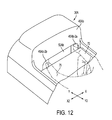
- FIGS. 11A, 11 B, 1 C, 12 , 13 , 14 A, 14 B and 14 C A description will now be given of another subscriber identity card loading mechanism 50 A by referring to FIGS. 11A, 11 B, 1 C, 12 , 13 , 14 A, 14 B and 14 C.
- the subscriber card loading mechanism 50 A includes a housing 51 A and a card holder 52 A, which holds the subscriber identity card 22 and is loaded to the housing 51 A.
- the subscriber card loading mechanism 50 A has a structure in which the card holder 52 A has handle portions located on sides X 1 and X 2 .
- the other portions of the card loading mechanism 50 A are the same as corresponding those of the card loading mechanism 50 .
- handle portions 52 A c - 3 A and 52 A c - 3 b are provided on the sides X 1 and X 2 of a front panel portion 52 A b .
- the handle portion 52 A c - 3 a is provided to a spring portion 52 A c , which has an engagement craw 52 A c - 2 located at the tip end of the spring portion 52 A a .
- the spring portion 52 A a is resiliently bent in the width direction of the portable telephone set 30 A.
- the card holder 52 A is inserted so that the rail portions are guided by guide grooves of the housing 51 A.
- the engagement craw 52 A c - 2 engages with a recess portion 51 A b of the housing 51 A.
- a card holder insertion opening 45 A b - 1 is formed in a vertical wall 45 A b of a battery pack mounting portion 45 A of the portable telephone set 30 A. Further, finger insertion recess portions 45 A b - 2 a and 45 A b - 2 b are formed on the sides X 1 and X 2 of the card holder insertion opening 45 A b - 1 .
- a thumb finger 75 is inserted into the recess portion 45 A b - 2 b , and the forefinger 70 is inserted into a finger insertion opening 45 A b - 2 ba .
- the handle portions 52 A c - 3 a and 52 A c - 3 b are slightly gripped, and the spring portion 52 A c is bent so that the engagement craw 52 A c - 2 is drawn from the recess portion 51 A p .
- the card holder 52 A is drawn in the direction Y 2 , and is finally detached from the housing 51 A.
- the card holder 52 A can be drawn to the table while gripping the handle portions 52 A c - 3 a and 52 A c - 3 b without gripping again.
- the operation steps of the subscriber identity card loading mechanism 50 A are the same as those of the mechanism 50 , and a description thereof will be omitted.
- FIGS. 15A, 15 B and 15 C show a variation of the detection switch 51 c .
- a detection switch 5 A c shown in these figures includes a first contact member 101 and a second contact member 102 .
- the detection switch 51 A c is normally maintained in the closed state, and is located at an end of the subscriber identity card loading mechanism 50 in the direction Y 1 .
- the detection switch 51 A c is pushed by the end surface 22 f of the subscriber identity card 22 located in the direction Y 1 and is thus opened when the card holder with the card 22 loaded thereto is loaded to the housing.
- the switch having a spring property will close upon disengagement of the card holder with the subscriber identity card.
- the detection switch 51 A c provided in the end of the mechanism in the direction Y 1 is attractive when the subscriber identity card has a large number of electrodes, for example, eight electrodes, and a large number of terminal members is required to be formed on the bottom of the housing.
- the present invention is directed to the use of the subscriber identity card.
- the present invention is not limited to the subscriber identity card, and includes any card in which information is stored.
Abstract
A portable telephone set includes a case having first and second sides opposite to each other, a group of keys is located on the first side of the case, and a card loading mechanism. The case includes first and second portions located on the second side. The first portion can accommodate a battery pack, and the second portion is next to the first portion and accommodates the card loading mechanism. A card in which information is stored can be loaded to the card loading mechanism.
Description
This is a division of application Ser. No. 09/017,395 filed Feb. 2, 1998 now U.S. Pat. No. 6,101,372.
1. Field of the Invention
The present invention relates to portable telephone sets, and more particularly to a portable telephone set suitable for a global system for mobile communication (GSM).
Recently, it has been considered in Japan to employ, as a communication system using portable telephone sets, the GSM which has been employed in Europe. The GSM does not require registration of a telephone number for each portable telephone set. Each individual (subscriber) is assigned to a subscriber identity module in which information concerning the subscriber is stored. If the subscriber exchanges the old portable telephone set by a new one, the subscriber identity module is detached from the old telephone set and is then inserted into the new one. If the rent portable telephone set is used, the subscriber inserts the own subscriber identity module into the set. Thus, the new or rent portable telephone set can be used as the subscriber own portable telephone set.
It has been considered that the subscriber identity module is realized by a compact subscriber identity card in which an integrated circuit including a memory is built. Such a card has a size of, for instance, 25 mm×15 mm.
The portable telephone set has been required to be thin and have a structure which enables the subscriber identity card to be easily detached therefrom.
There is another card which can be inserted into the portable telephone set. Such a card stores information important to the subscriber, such as subscriber identity information and accounting information. It is not desired to easily detach, from the portable telephone set, the information cards suitable for the portable telephone set as described above in terms of privacy protection. The portable telephone set is required to satisfy the above.
In the present specification, the cards to be attached to the portable telephone sets are referred to as portable telephone information cards. The portable telephone information cards include the above subscriber identity card, and another card which stores information other than the subscriber identity information.
2. Description of the Related Art
FIGS. 1A and 1B are diagrams of a portable telephone set 10 for the GSM disclosed in Japanese Laid-Open Patent Application No. 8-265404. A battery pack 11 can be attached to the back surface of the portable telephone set 10. A card loading mechanism 12 is provided in a bottom surface portion of a battery pack mount portion 13 provided to the back surface of the portable telephone set 10, that is, the back surface of the mounted battery pack 11. The battery pack mount portion 13 has a bottom plate 14, in which a rectangular opening 15 is formed.
The subscriber identity card loading mechanism 12 is mainly composed of a housing 20 and a holder 21. The housing 20 is fixed to the inside of the portable telephone set 10, and faces the opening 15. The holder 21 is joined to the housing by a hinge.
A subscriber identity card 22 can be mounted as follows. The holder 21 is rotated and set upright. Then, the subscriber identity card 22 is inserted into the holder 21, which is then depressed and rotated. Thus, the card 22 passes through the opening 15 and is engaged with the housing 20.
A subscriber identity card 22 can be taken out by the reverse operation. It should be noted that the subscriber identity card 22 which is mounted cannot be taken out unless the battery pack 11 is taken out.
The above portable telephone set 10 has the following problems.
The battery pack mount portion 13 located in the back surface of the portable telephone set 10 includes a slight recess. A circuit board, a tenkey and other components are tightly provided in a portion 16 opposite to the battery pack mount portion 13. Thus, no space is available in which a new mechanism is provided. The card loading mechanism 12 is provided in the above portion 16, and thus has an increased thickness t1. Hence, the thickness t3 of the portable telephone set 10 is equal to the sum of the thickness t2 necessary to provide the circuit board, the tenkey and other components and the thickness t1 of the card loading mechanism 12. The thickness t3 prevents down-sizing of the portable telephone set 10.
The holder 21 cannot be detached from the housing 20. Hence, it is necessary to take the portable telephone 10 by hand in order to take out the subscriber identity card 22 from the holder 21 and insert the subscriber identity card 22 into the holder 21. The above is troublesome. Further, the card loading mechanism 12 has a complex structure.
A detection switch detects the holder 21 even when the holder 21 having no card is mounted. Hence, if the subscriber dials with no card inserted into the holder 21, the portable telephone set 10 starts a corresponding calling procedure although it is not completed.
It is a general object of the present invention to provide a portable telephone set in which the above disadvantages are eliminated.
A more specific object of the present invention is to provide a compact portable telephone set having a simplified card loading mechanism.
The above objects of the present invention are achieved by a portable telephone set comprising: a case having first and second sides opposite to each other; a group of keys located on the first side of the case; and a card loading mechanism. The case includes first and second portions located on the second side. The first portion can accommodate a battery pack, and the second portion is next to the first portion and accommodates the card loading mechanism. A card in which information is stored can be loaded to the card loading mechanism. The card loading mechanism and the battery pack can be arranged side by side, so that the thickness of the portable telephone set can be reduced.
The above portable telephone set may be configured so that: the case has a wall interposed between the first and second portions; and the wall has an opening through which the card can be inserted into the second portion and loaded to the card loading mechanism. Hence, the card cannot be detached unless the battery pack is detached. Thus, it is possible to prevent the card from happening to be detached from the portable telephone set.
The portable telephone set may be configured so that the second portion includes a protrusion with respect to a bottom portion of the first portion. Such a protrusion means that there is a comparatively large spatial area in the portable telephone set. Hence, the card loading mechanism can be provided in the second portion without a particular difficulty.
The portable telephone set may be configured so that the card loading mechanism comprises: a housing located in the second portion; and a card holder having a card accommodating portion in which the card can be accommodated, the card holder having a spring portion which portion has a handle portion with which a finger can be engaged, and an engagement craw which can engage with a part of the housing when the card holder is inserted into the housing. A simple structure of the card loading mechanism can be realized.
The portable telephone set may be configured so that the spring portion is formed of a resin. Thus, the spring portion having a resilient property can be realized with ease.
The portable telephone set may be configured so that: the spring portion is formed of a resin and can be resiliently bent in a thickness direction of the portable telephone set; and the handle portion is located in a free end of the spring portion. The card holder can easily be drawn by a single-finger operation.
The portable telephone set may be configured so that: the spring portion is formed of a resin and can be resiliently bent in a thickness direction of the portable telephone set; the handle portion is located in a free end of the spring portion; and the card holder has another handle portion located opposite to the handle portion. The card holder can easily be drawn by using two fingers such as the thumb finger and the forefinger.
The portable telephone set may be configured so that: the card holder has a card holding portion having a spring property and projecting from a side of the card accommodating portion; and the card holding portion engages with a part of the card so that the card can be restricted in the second portion. The card holding portion of the card holder can certainly hold the card.
The portable telephone set may be configured so that the card loading mechanism comprises: a housing located in the second portion; a card holder having a card accommodating portion in which the card can be accommodated; and a detection switch which detects a situation in which the card holder with the card loaded thereto is inserted into the housing. Hence, even if the card holder with no card accommodated therein is loaded to the portable telephone set, the portable telephone set can be prevented from performing a meaningless or wasteful operation such as a calling procedure.
The portable telephone set may be configured so that the detection switch has a terminal having a spring property, the terminal which can be engaged with the card accommodated in the card holder. The same advantages as described above can be obtained.
The portable telephone set may be configured so that the card holder has a spring portion which portion has a handle portion with which a finger can be engaged, and an engagement craw which can engage with a part of the housing when the card holder is inserted into the housing. The card holding portion of the card holder can certainly hold the card.
The portable telephone set may be configured so that the card loading mechanism can receive the card in a state in which the battery pack is detached from the first portion. Hence, the card can be prevented from being drawn in the state in which the battery pack is attached to the portable telephone set.
Other objects, features and advantages of the present invention will become more apparent from the following detailed description when read in conjunction with the accompanying drawings, in which:
FIGS. 1A and 1B are diagrams of a conventional portable telephone set;
FIG. 2A is a partially-cutout plan view of a portable telephone set according to an embodiment of the present invention;
FIG. 2B is a cross-sectional view of the portable telephone set shown in FIG. 2A;
FIG. 3 is an exploded perspective view of the portable telephone set shown in FIGS. 2A and 2B;
FIG. 4 is an enlarged perspective view taken along an arrow III shown in FIG. 2B;
FIG. 5 is a perspective view of a subscriber identity card loading mechanism of the portable telephone set;
FIG. 6 is a perspective view of a card holder of the portable telephone set;
FIGS. 7A, 7B, 7C, 7D and 7E are diagrams of the subscriber identity card holding mechanism to which a card is loaded;
FIGS. 8A and 8B are diagrams of a detection switch built in the portable telephone set;
FIG. 9 is an enlarged perspective view showing an operation of drawing the card holder from the portable telephone set;
FIG. 10 is an enlarged perspective view showing an operation of loading the card holder
FIGS. 11A, 11B and 11C show another subscriber identity loading mechanism;
FIG. 12 is an enlarged perspective view of a state in which the subscriber identity card loading mechanism is installed in the portable telephone set;
FIGS. 13A and 13B are diagrams of a card holder;
FIGS. 14A, 14B and 14C are diagrams of a housing; and
FIGS. 15A, 15B and 15C are diagrams of another detection switch.
FIGS. 2A and 2B are diagrams of a portable telephone set 30 which can be applied to the GSM according to an embodiment of the present invention. Further, FIG. 3 is an exploded perspective view of the portable telephone set 30. FIG. 4 is an enlarged perspective view taken along arrow III shown in FIG. 2B.
The portable telephone set 30 has a front case 32 and a back case 34 between which a printed wiring board unit 36 is interposed. The whole case of the portable telephone set 30 includes the cases 32 and 34. The front case 32 is equipped with a key group sheet 31 on which a plurality of keys are arranged. The back case 34 is equipped with an antenna 37. The printed wiring board unit 36 is equipped with a liquid crystal unit 35. The front case 32, the rear case and the printed wiring board unit 36 are longitudinal in directions Y1 and Y2. A housing 51, which will be described in detail later, is attached to the printed wiring board unit 36. The portable telephone set 30 has a front surface facing in a direction Z2, and a back surface facing in a direction Z1.
A plurality of keys 39 are arranged in a front surface 30 a of the portable telephone set 30 so that the keys 39 occupy an area located in a direction Y2 with respect to the center in the longitudinal direction. A display window 40 of the liquid crystal unit 35 and an acoustic output part 41 formed of a speaker are provided in an area located in a direction Y1 with respect to the keys 39. An acoustic input part 42 formed of a microphone is provided in the area located in the direction Y2 with respect to the key 39.
A battery pack mounting portion 45 is provided to the back surface 30 b of the portable telephone set 30 and is located in the area extending in the direction Y2 from the center in the longitudinal direction. In other words, the battery pack mounting portion 45 is located in the portion corresponding to the arrangement of the keys 39. A battery pack 46 having a length approximately equal to half the length of the portable telephone set 30 is mounted on the battery pack mounting portion 45. The battery pack mounting portion 45 has a recess which causes the back surface 30 b of the portable telephone set 30 with the battery pack 46 mounted to be a flat surface. A portion 47, which is adjacent to the battery pack mounting portion 45 in the longitudinal direction and totally occupies the whole located in the direction Y1 with respect to the battery pack mounting portion 45, has a projection projecting from a bottom surface 45 a in the direction Z1. Hereinafter, the portion 47 will be referred to as a battery pack mount adjacent portion The interface between the battery pack mounting portion 45 and the battery pack adjacent portion 47 is a vertical wall 45 b which stands upright in the direction Z1 from the bottom surface 45 a. A card holder inserting opening 45-b is formed in a lower end portion of the vertical wall 45 b. The lower side of the vertical wall 45 b corresponds to the position in which the card holder insertion opening 45-b is formed. Hence, as will be described in detail later with reference to FIG. 10, when the card holder 52 is placed on the bottom surface 45 a of the battery pack mounting portion 45 of the portable telephone set 30, the card holder 52 faces the card holder insertion opening 45-b.
The portable telephone set 30 has a subscriber identity card loading mechanism 50, which is provided in an inner space 47 a of the battery pack mount adjacent portion 47. The mechanism 50 is built in the portable telephone set 30 without any increase in the thickness thereof because the battery pack mount adjacent portion 47 projects from the bottom surface 45 a of the battery pack mounting portion 45, and is located in the area which has a larger spatial margin than the other area of the portable telephone set 30. Further, the size of the card loading mechanism 50 itself is small. The thickness of the portable telephone set 30, which is denoted as t10, is equal to that obtained when the card loading mechanism 50 is not installed.
A description will be given, with reference to FIGS. 5, 6 and 7A through 7E, of the structure of the subscriber identity card loading mechanism 50.
The card loading mechanism 50 includes the housing 51 and the card holder 52 which holds the subscriber identity card 22 and is attached to the housing 51. The card loading mechanism 50 has an upper surface facing in the direction Z1, a lower surface in the direction Z2, a front surface in the direction Y2, and a rear portion in the direction Y1. The width of the mechanism 50 extends in the directions X1 and X2.
As shown in FIG. 6, the subscriber identity card 22 includes a built-in integrated circuit 22 a and six electrodes 22 b provided to the lower surface of the card 22. Further, the subscriber identity card 22 has a chamfered corder 22 c.
The card holder 52 is a synthetic resin molded component, and has a flat shape which is long in the directions Y1 and Y2. The card holder 52 includes a subscriber identity card accommodating portion 52 a provided to the lower surface side, a front panel portion 52 b, and a cantilever plate spring 52 c provided to the upper surface side. Further, the card holder 52 has rail portions 52 d and 52 e which are provided to ends thereof located in the directions X1 and X2 and extend in the directions Y1 and Y2.
The subscriber identity card accommodating portion 52 a has a size which corresponds to the subscriber identity card 22, and a depth “a” corresponding to the thickness t20 of the card 22 so that the card accommodating portion 52 a has a flat recess shape into which the subscriber identity card can be accommodated. The card accommodating portion 52 a includes a slant portion 52 a-1, which corresponds to the chamfered corner 22 c. Two plate springs 52 a-2 and 52 a-3 made of synthetic resin are provided to the end X2 of the card accommodating portion 52 a so that the free ends thereof face each other and are arranged in a line in the directions Y1 and Y2. The plate springs 52 a-2 and 52 a-3 can be resiliently bent in the direction X2. The plate springs 52 a-2 and 52 a-3 function as subscriber identity card holding portions having a spring property. Further, holes 52 a-4 and 52-5 for pushing out the subscriber identity card are formed in the vicinity of the ends of the bottom of the card accommodating portion 52 a in the direction Y1.
The front panel portion 52 b has a U-shaped cutout portion 52 b-1 located at the center thereof. Protrusions 52 b-2 and 52 b-3 which protrude in the direction Z1 are provided on both sides of the U-shaped cutout portion 52 b-1. The U-shaped cutout portion 52 b-1 functions to accommodate a handle portion 52 c-3 which will be described in detail later. The protrusions 52 b-2 and 52 b-3 come into contact with a counter U-shaped frame portion 51 a-4 a which will also be described later.
The cantilever plate spring 52 c is integrally formed when molding the card holder 52, and is formed so that a portion of the upper surface of the card holder 52 in the width direction (in the directions X1 and X2) is cut and raised. The plate spring 52 c has a width W1 that is approximately equal to ¼ of the width W2 of the card holder 52. The plate spring 52 c has a root portion 52 c-1 located in the center of the card holder 52 in the directions Y1 and Y2. The root portion 52 c-1 stands upright by a distance “b” so that the remaining portion of the plate spring 52 c horizontally extends to the front panel portion 52 b in the direction Y2. The cantilever plate spring 52 c has an engagement craw 52 c-2 that is located in the center of the upper surface thereof and projects in the direction Z1. Further, the cantilever plate spring 52 c has the handle portion 52 c-3 located at the end thereof. The engagement craw 52 c-2 has a slant surface 52 c-2 a in the direction Y1, and a vertical surface 52 c-2 b in the direction Y2. The handle portion 52 c-3 has a recess portion 52 c-3 a on the upper surface oriented in the direction Y1. The recess portion 52 c-3 a makes it possible for the end of the forefinger of the hand of the operator to be easily engaged with the handle 52 c-3. Further, the handle portion 52 c-3 is located in the U-shaped cutout portion 52 b-1 of the front panel portion 52 b.
When the handle portion 52 c-3 is pushed in the direction Z2, the cantilever plate spring 52 c is bent and the engagement craw 52 c-2 is thus displaced in the direction Z2. The cantilever plate spring 52 c is located over the upper surface of the card holder 52 by the distance “b”. Hence, even if the spring portion 52 c is bent, it is not entered into the subscriber identity card accommodating portion 52 a.
The housing 51 includes a housing main body 51 a made of synthetic resin, a plurality of terminals 51 b fixed to the housing main body 51 a, and a detection switch 51 c provided to the housing main body 51 a. The housing 51 has a size greater than the card holder 52.
The housing main body 51 a includes a bottom, plate portion 51 a-1, sidewall portions 51 a-2 and 51 a-3, and a counter U-shaped frame portion 51 a-4. The sidewall portions 51 a-2 and 52-3 which are located on both the sides of the housing main body 51 a in the directions X1 and X2 and extend upwards in the direction Z1. The counter frame portion 51 a-4 are located on both the sides in the direction Y2. Guide grooves 51 a-5 and 51-6 are formed in the parts of the sidewall portions 51 a-2 and 51 a-3 which face the bottom plate portion 51 a-1. A guard holder accommodating portion 51 d is formed on the upper surface side of the bottom plate portion 51 a-1. The guard holder accommodating portion 51 d has a flat space partitioned by the sidewall portions 51 a-2 and 51 a-3. The counter U-shaped frame portion 51 a-4 forms an entrance 51 e to the card holder accommodating portion 51 d. Two bosses 51 a-1 a and 51 a-1 b for defining the attachment position of the housing 51 are formed on the lower surface of the bottom plate portion 51 a-1.
The counter U-shaped frame portion 51 a-4 includes a central counter U-shaped frame portion 51 a-4 a, which is a step portion higher than the frame portion 51 a-4. The portion 51 a-4 a is provided to allow the cantilever plate spring 52 c of the card holder 52 to pass therethrough. Two upright portions 51 a-4 b and 51 a-4 c located on both sides of the frame portion 51 a-4 a receive the protrusions 52 b-2 and 52 b-3 when the card holder 52 is inserted. A cut portion 51 a-4 e having a U shape corresponding to the size of the engagement craw 52 c-2 is formed in an end of the frame portion 51 a-4 a extending in the direction Y1. The frame portion 51 a-4 d functions as an engagement portion with which the engagement craw 52 c-2 is engaged.
The six terminal members 51 b are fixed to the upper surface 51 a-1 a of the bottom plate portion 51 a-1. Arc-shaped terminal portions 51 b-1 are respectively provided on the ends of the six terminal members 51 b so as to correspond to the six electrodes 22 b of the subscriber identity card 22. Terminal portions 51 b-2 provided on the other ends of the six terminal members 51 b extend outwards from the ends in the directions Y1 and Y2. The terminal portions 51 b-2 have the same height as that of the lower surface 51 a-1 b of the bottom plate portion 51 a-1.
Referring to FIG. 8A additionally, the detection switch 51 c has a first contact member 51 c-1 and an L-shaped second contact member 51 c-2, and is normally closed. The first contact member 51 c-1 and the second contact member 51 c-2 are fixed to the lower surface 51 a-1 b of the bottom plate portion 51 a-1. The first contact member 51 c-1 has one end located in the direction Y1, which end is fixed, while the other end thereof can flexibly be bent. The first contact 51 c-1 has a convex portion 51 c-1 a protruding in the direction Z1. More particularly, the convex portion 51 c-1 a slightly protrudes from the upper surface 51 a-1 a of the bottom plate portion 51 a-1 via an opening window 51 a-1 c of the bottom plate portion 51 a-1. The opening window 51 a-1 c (the convex portion 51 c-1 a) is disposed in a position in which the opening window 51 a-1 c is pushed by the subscriber identity card 22 held in the card holder 52 when the card holder 52 is inserted into the housing 51.
When the subscriber identity card 22 is not inserted into the card holder 52, the first contact member 51 c-1 is in contact with the second contact member 51 c-2, as shown in FIG. 8A. Hence, the detection switch 51 c is maintained in the closed state.
As shown in FIG. 3, the printed wiring board unit 36 has a flexible printed circuit board used to attach the housing 51 thereto. The flexible printed circuit board 60 extending from the inside of the printed wiring board unit 36 is folded and adheres to the upper surface of the unit 36. A plurality of lands 61 are provided to the flexible printed circuit board 60 so as to have an arrangement which corresponds to the terminal portions 51 b-2. Holes 62 are formed in the upper surface of the unit 36 and the board 60 so that the positions of the holes 62 correspond to those of the bosses 51 a-1 a and 51 a-1 b.
The housing 51 is positioned so that the bosses 51 a-1 a and 51 a-1 b are engaged with the holes 62. The terminal portions 51 b-2 are soldered to the lands 61. Then, the housing 51 is mounted on the upper surface of the printed wiring board unit 36 so that the entrance 51 e is oriented along the direction Y2.
The housing 51 can completely be accommodated in the battery pack mount adjacent portion 47, and the entrance 51 e faces a card holder insertion opening 45 b-1 of the vertical wall 45 b in the state in which the printed wiring board unit 36 is covered by the front case 32 and the back case 34.
As shown in FIG. 4, a finger inserting recess portion 45 b-2 is formed in the vertical wall 45 b in addition to the card holder insertion opening 45 b-1, which opening has a shape corresponding to the front panel portion 52 b of the card holder 52. The finger inserting recess portion 45 b-2 makes it easy for the forefinger of the operator to engage with the handle portion 52 c-3. The finger inserting recess portion 45 b-2 is located just above the card holder insertion opening 45 b-1, and is recessed in the direction Y1 so that the degree of recess is increased in the direction Z2.
In the state in which the card holder 52 is accommodated in the housing 51, as shown in FIG. 4, the front panel portion 52 b is stayed in the card holder insertion opening 45 b-1, and the handle portion 52 c-3 projects from the lower end of the finger inserting recess portion 45 b-2.
Next, a description will be given of a procedure and operation to be carried out when the operator who rents a portable telephone set inserts his or her own subscriber identity card 22 therein.
The above procedure is comprised of the following first to fifth steps. The first step is to detach the battery pack 46 from the portable telephone set 30. The second step is to take out the card holder 52 having no card. The third step is to insert the own subscriber identity card 22 into the card holder 52. The fourth step is to load the card holder 52 with the card 22 inserted therein to the housing 51. The fifth step is to attach the battery pack 46.
The above first to fifth steps will be described in more detail below.
In the first step, the battery pack 46 is detached from the portable telephone set 30. Hence, as shown in FIG. 4, the handle portion 52 c-3 is exposed.
In the second step, the card holder 52 having no card is drawn and taken out. As shown in FIG. 9, a forefinger 70 is inserted into the finger insertion recess portion 45 b-2. Then, as indicated by an arrow 71, the handle portion 52 c-3 is pressed in the direction Z2, and is thereafter drawn in the direction Y2 as indicated as indicated by an arrow 72. In the operation of pressing the handle portion 52 c-3 in the direction Z2, as shown in FIG. 7D, the cantilever plate spring 52 c is bent in the direction Z2, and the engagement craw 52 c-2 is disengaged from the central counter U-shaped frame portion 51 a-4 a. Hence, the card holder 52 is released from the locked state in which it is locked to the housing 51. The forefinger 70 strongly engages with the recess portion 52 c-3 a of the handle portion 52 c-3. In the subsequent operation, the craw portion 52 c-2 passes below the frame portion 51 a-4 a, so that the card holder 52 is drawn to the outside of the housing 51.
As described above, the card holder 52 can be drawn by the operation of only the forefinger.
In the third step, the subscriber identity card 22 of the operator is inserted in the card holder 52. The card 22 is lightly pushed in the subscriber identity card accommodating portion 52 a in the direction reverse to the direction shown in FIG. 6A so that the card accommodating portion 52 a faces up. hence, the plate springs 52 a-2 and 52 a-3 are resiliently bent, so that the card 22 is loaded to the card holder 52. In this state, the card holder 52 is detached from the portable telephone set 30. Hence, it is very easy for the operator to load his or her own subscriber identity card 22 to the subscriber identity card accommodating portion 52 a.
The card 22 can be correctly loaded to the card holder 52 due to the function of the chamfered portion 22 c of the card 22 and the slant portion 52-1 of the card accommodating portion 52 a. The card 22 is pushed in the single direction by the plate springs 52 a-2 and 52 a-3. Hence, even when the card holder 52 is turned reversely so that the card accommodating portion 52 a faces down, the card 22 does not drop off.
In the fourth step, the card holder 52 is inserted into and loaded to the housing 51.
As shown in FIG. 10, the card holder 52 is placed on the bottom surface 45 a of the battery pack loading portion 45 of the portable telephone set 30 so that the card holder 52 faces the card holder insertion opening 45 b-1. Then, the card holder 52 is made to slide in the direction Y1 so that it passes through the card holder insertion opening 45 b-1. Hence, the card holder 52 is inserted into the housing 51. When the card holder 52 is placed on the bottom surface 45 a of the battery pack mounting portion 45, the card holder 52 faces the card holder insertion opening 45 b-1. This arrangement facilitates the operation of orienting the card holder 52 toward the card holder insertion opening 45 b-1, so that the card holder 52 can easily be loaded to the housing 51.
The card holder 52 is guided and regulated in the directions X1, X2, Z1 and Z2 so that the rail portions 52 d and 52 e engages with the guide grooves 51 a-5 and 51 a-6 of the housing 51. As shown in FIG. 4, the card holder 52 is inserted until the handle portion 52 c-3 is engaged with the card holder insertion opening 45 b-1.
The card holder 52 is prevented from moving in the direction Z1 because the rail portions 52 d and 52 e engage with the guide grooves 51 a-5 and 51 a-6. The subscriber identity card 22 is prevented from moving in the direction Z1 due to the function of the card holder 52. Hence, the subscriber identity card 22 cannot move in the direction Z1.
As shown in FIG. 7E, when the engagement craw 52 c-2 comes into contact with the central counter U-shaped frame portion 51 a-4 a, the slant surface 52 c-2 is guided by the frame portion 51 a-4 a, and the cantilever plate sprint 52 c is resiliently bent in the direction Z2. Hence, the engagement craw 52 c-2 enters below the frame portion 51 a-4 a. In other words, the card holder 52 can be inserted into the housing 51 by merely pushing the card holder 52 in the direction Y2 rather than specially depressing the handle portion 52 c-3. This also makes it easy to load the card holder 52 to the housing 51.
When the card holder 52 is inserted into the final position of the housing 51, the engagement craw 52 c-2 passes through the central counter U-shaped frame portion 51 a-4 a, and the cantilever plate spring 52 c is resiliently returned to the original state. Further, the vertical surface 52 c-2 b of the engagement craw 52 c-2 engages with the frame portion 51 a-4 a. Thus, the card holder 52 is locked to the housing 51 and is prevented from being detached therefrom.
When the card holder 52 is inserted into the final position of the housing 51, the six electrodes 22 b of the subscriber identity card 22 come into contact with the six arc-shaped terminal portions 51 b-1. As shown in FIG. 8B, the lower surface 22 e of the subscriber identity card pushes down the convex portion 51 c-1 a. Hence, the first contact member 51 c-1 is detached from the second contact member 51 c-2 and the detection switch 51 c is opened. Information which indicates that the subscriber identity card 22 has been loaded to the card holder 52 is supplied to a given circuit of the portable telephone set 30. As has been described previously, the subscriber identity card 22 cannot move in the direction Z1. Hence, the contacts between the electrodes 22 b and the terminal portions 51 b-1 can be definitely established and the detection switch 51 c can be definitely closed.
In the fifth step, the battery pack 46 is attached to the portable telephone set 30. In this state, the portable telephone set 30 is switched to a state in which the owner of the subscriber identity card 22 can be identified. Since the detection switch 51 c is opened, the portable telephone set 30 operates normally. In the state in which the battery pack 46 is attached to the portable telephone set 30, the handle portion 52 c-3 is hidden by the battery pack 46. Hence, the subscriber identity card 22 cannot be detached from the portable telephone set 30 in the state in which the battery pack 46 is attached thereto. As a result, there is no possibility that the subscriber identity card 22 happens to be detached from the portable telephone set 30.
The detection switch 51 c is closed in the state in which the card holder 52 with no card is loaded to the portable telephone set 30, which is not thus operated. Hence, it is possible to prevent the occurrence of the wasteful calling procedure which is encountered in the prior art.
The card holder 52 with the card 22 attached can be detached as described above. As shown in FIG. 7C, the cantilever plate spring 52 c is located, by a relatively large distance “c”, above the upper surface of the subscriber identity card 22 loaded to the card holder 52. Hence, even if the cantilever plate spring 52 is bent downwards, it cannot come into contact with the subscriber identity card 22, and hence the engagement craw 52 c-2 can be certainly detached from the central counter U-shaped frame portion 51 a-4 a. Hence, the subscriber identity card 22 is detached from the card holder 52, the card 22 is pushed by a tip end of a ballpoint pen or the like, which is inserted in the hole 52 a-4 and/or 52 a `-5. Hence, the subscriber identity card 22 can easily be detached.
A description will now be given of another subscriber identity card loading mechanism 50A by referring to FIGS. 11A, 11B, 1C, 12, 13, 14A, 14B and 14C.
The subscriber card loading mechanism 50A includes a housing 51A and a card holder 52A, which holds the subscriber identity card 22 and is loaded to the housing 51A. The subscriber card loading mechanism 50A has a structure in which the card holder 52A has handle portions located on sides X1 and X2. The other portions of the card loading mechanism 50A are the same as corresponding those of the card loading mechanism 50.
As shown in FIG. 13A, handle portions 52Ac-3A and 52Ac-3 b are provided on the sides X1 and X2 of a front panel portion 52Ab. The handle portion 52Ac-3 a is provided to a spring portion 52Ac, which has an engagement craw 52Ac-2 located at the tip end of the spring portion 52Aa. Further, the spring portion 52Aa is resiliently bent in the width direction of the portable telephone set 30A. The card holder 52A is inserted so that the rail portions are guided by guide grooves of the housing 51A. The engagement craw 52Ac-2 engages with a recess portion 51Ab of the housing 51A.
As shown in FIG. 12, a card holder insertion opening 45Ab-1 is formed in a vertical wall 45Ab of a battery pack mounting portion 45A of the portable telephone set 30A. Further, finger insertion recess portions 45Ab-2 a and 45Ab-2 b are formed on the sides X1 and X2 of the card holder insertion opening 45Ab-1.
A thumb finger 75 is inserted into the recess portion 45Ab-2 b, and the forefinger 70 is inserted into a finger insertion opening 45Ab-2 ba. Then, the handle portions 52Ac-3 a and 52Ac-3 b are slightly gripped, and the spring portion 52Ac is bent so that the engagement craw 52Ac-2 is drawn from the recess portion 51Ap. In this state, the card holder 52A is drawn in the direction Y2, and is finally detached from the housing 51A. In the above manner, the card holder 52A can be drawn to the table while gripping the handle portions 52Ac-3 a and 52Ac-3 b without gripping again.
The operation steps of the subscriber identity card loading mechanism 50A are the same as those of the mechanism 50, and a description thereof will be omitted.
FIGS. 15A, 15B and 15C show a variation of the detection switch 51 c. A detection switch 5Ac shown in these figures includes a first contact member 101 and a second contact member 102. As shown in FIGS. 15A and 15B, the detection switch 51Ac is normally maintained in the closed state, and is located at an end of the subscriber identity card loading mechanism 50 in the direction Y1. As shown in FIG. 15C, the detection switch 51Ac is pushed by the end surface 22 f of the subscriber identity card 22 located in the direction Y1 and is thus opened when the card holder with the card 22 loaded thereto is loaded to the housing. The switch having a spring property will close upon disengagement of the card holder with the subscriber identity card.
The detection switch 51Ac provided in the end of the mechanism in the direction Y1 is attractive when the subscriber identity card has a large number of electrodes, for example, eight electrodes, and a large number of terminal members is required to be formed on the bottom of the housing.
The above-mentioned embodiments of the present invention are directed to the use of the subscriber identity card. However, the present invention is not limited to the subscriber identity card, and includes any card in which information is stored.
The present invention is not limited to the specifically disclosed embodiments, and variations and modifications may be made without departing from the scope of the present invention.
Claims (7)
1. A portable telephone set comprising:
a case having first and second sides opposite to each other;
a group of keys located on the first side of the case; and
a card loading mechanism,
the case including first and second portions located on the second side,
the first portion which can accommodate a battery pack, and the second portion which is next to the first portion and accommodates the card loading mechanism,
a card in which information is stored being located to the card loading mechanism, wherein the card loading mechanism comprises:
a housing located in the second portion; and
a card holder having a card accommodating portion in which the card can be accommodated,
the card holder having a stopping mechanism which stops the card holder in the housing with the card holder not protruding from the second portion.
2. The portable telephone set as claimed in claim 1 , further comprising:
another mechanism which applies an urging force to the card holder in a direction reverse to that in which the card holder is inserted when the card holder is inserted into the housing.
3. The portable telephone set as claimed in claim 2 , further comprising:
a detector which detects a situation in which the card holder is inserted into the housing.
4. The portable telephone set as claimed in claim 3 , wherein said another mechanism acts as the detector.
5. A portable telephone set comprising:
a case having first and second sides opposite to each other;
a group of keys located on the first side of the case; and
a card loading mechanism,
the case including first and second portions located on the second side,
the first portion which can accommodate a battery back, and the second portion which is next to the first portion and accommodates the card loading mechanism,
a card in which information is stored being located to the card loading mechanism where the card loading mechanism further comprises:
a housing located in the second portion,
a card holder having a card accommodating portion in which the card can be accommodated; and
a detection switch which detects a situation in which the card holder with the card loaded thereto is inserted into the housing, wherein the card holder has a stopping mechanism which stops the card holder in the housing with the card holder not protruding from the second portion.
6. The portable telephone set as claimed in claim 5 , further comprising:
another mechanism which applies an urging force to the card holder in a direction reverse to that in which the card holder is inserted when the card holder is inserted into the housing.
7. The portable telephone set as claimed in claim 3 , further comprising:
a detector which detects a situation in which the card holder is inserted into the housing, wherein said another mechanism acts as the detector.
Priority Applications (3)
| Application Number | Priority Date | Filing Date | Title |
|---|---|---|---|
| US09/518,827 US6580923B1 (en) | 1997-06-03 | 2000-03-06 | Portable telephone set |
| US10/414,449 US7925301B2 (en) | 1997-06-03 | 2003-04-15 | Portable telephone set with a card inserted through a battery holding space |
| US13/037,540 US8666449B2 (en) | 1997-06-03 | 2011-03-01 | Portable telephone set |
Applications Claiming Priority (4)
| Application Number | Priority Date | Filing Date | Title |
|---|---|---|---|
| JP9-145407 | 1997-06-03 | ||
| JP14540797A JP4237834B2 (en) | 1997-06-03 | 1997-06-03 | Mobile phone |
| US09/017,395 US6101372A (en) | 1997-06-03 | 1998-02-02 | Portable telephone set |
| US09/518,827 US6580923B1 (en) | 1997-06-03 | 2000-03-06 | Portable telephone set |
Related Parent Applications (1)
| Application Number | Title | Priority Date | Filing Date |
|---|---|---|---|
| US09/017,395 Division US6101372A (en) | 1997-06-03 | 1998-02-02 | Portable telephone set |
Related Child Applications (1)
| Application Number | Title | Priority Date | Filing Date |
|---|---|---|---|
| US10/414,449 Division US7925301B2 (en) | 1997-06-03 | 2003-04-15 | Portable telephone set with a card inserted through a battery holding space |
Publications (1)
| Publication Number | Publication Date |
|---|---|
| US6580923B1 true US6580923B1 (en) | 2003-06-17 |
Family
ID=15384552
Family Applications (2)
| Application Number | Title | Priority Date | Filing Date |
|---|---|---|---|
| US09/017,395 Expired - Lifetime US6101372A (en) | 1997-06-03 | 1998-02-02 | Portable telephone set |
| US09/518,827 Expired - Lifetime US6580923B1 (en) | 1997-06-03 | 2000-03-06 | Portable telephone set |
Family Applications Before (1)
| Application Number | Title | Priority Date | Filing Date |
|---|---|---|---|
| US09/017,395 Expired - Lifetime US6101372A (en) | 1997-06-03 | 1998-02-02 | Portable telephone set |
Country Status (4)
| Country | Link |
|---|---|
| US (2) | US6101372A (en) |
| JP (1) | JP4237834B2 (en) |
| DE (1) | DE19806844C2 (en) |
| GB (1) | GB2326050B (en) |
Cited By (12)
| Publication number | Priority date | Publication date | Assignee | Title |
|---|---|---|---|---|
| US20020061736A1 (en) * | 2000-11-22 | 2002-05-23 | Nokia Corporation | Housing for an electronic device |
| US6717817B2 (en) * | 2002-09-09 | 2004-04-06 | Wen-Tsung Liu | Tray-style flash memory drive |
| US20040132493A1 (en) * | 2002-12-27 | 2004-07-08 | Yi Yen Lin | Mobile phone with SIM card holder |
| US20040248524A1 (en) * | 2001-10-16 | 2004-12-09 | Arnaud Flegeo | Electronic apparatus having a removable front-face element |
| US20050075138A1 (en) * | 2003-10-06 | 2005-04-07 | Page Kevin D. | Low profile electronic card holder and device using same |
| US20050158617A1 (en) * | 2002-04-16 | 2005-07-21 | Noriyoshi Satoh | Portable terminal |
| US20080153320A1 (en) * | 2006-12-20 | 2008-06-26 | Yi-Wen Lin | Space-saving IC card and card slot arrangement |
| US20100073891A1 (en) * | 2008-09-25 | 2010-03-25 | Shenzhen Futaihong Precision Industry Co., Ltd. | Chip card holder and portable electronic device using the same |
| US20100159729A1 (en) * | 2008-12-19 | 2010-06-24 | Chi Mei Communication Systems, Inc. | Sim card fixing assembly |
| US20110312270A1 (en) * | 2010-06-22 | 2011-12-22 | At&T Mobility Ii Llc | Near Field Communication Adapters |
| US20120202366A1 (en) * | 2011-02-09 | 2012-08-09 | Molex Incorporated | Electrical connector device |
| US20150011118A1 (en) * | 2013-07-02 | 2015-01-08 | Japan Aviation Electronics Industry, Limited | Connector |
Families Citing this family (91)
| Publication number | Priority date | Publication date | Assignee | Title |
|---|---|---|---|---|
| US6543695B1 (en) * | 1996-08-02 | 2003-04-08 | Symbol Technologies, Inc. | Housing for hand held scanner |
| US7321783B2 (en) * | 1997-04-25 | 2008-01-22 | Minerva Industries, Inc. | Mobile entertainment and communication device |
| US20040157612A1 (en) * | 1997-04-25 | 2004-08-12 | Minerva Industries, Inc. | Mobile communication and stethoscope system |
| US6480699B1 (en) * | 1998-08-28 | 2002-11-12 | Woodtoga Holdings Company | Stand-alone device for transmitting a wireless signal containing data from a memory or a sensor |
| JP2000165085A (en) * | 1998-11-24 | 2000-06-16 | Nec Corp | Flexible board, unnecessary radiation preventing method therefor and portable telephone |
| JP3717319B2 (en) * | 1998-11-27 | 2005-11-16 | 松下電器産業株式会社 | Key pressing device mounting structure |
| EP1026868B1 (en) * | 1999-02-01 | 2002-08-21 | Telefonaktiebolaget Lm Ericsson | Communication Station |
| EP1074936B1 (en) * | 1999-02-05 | 2006-04-26 | Mitsubishi Denki Kabushiki Kaisha | Device for attaching/detaching sim card |
| GB2346759B (en) * | 1999-02-12 | 2003-06-18 | Nokia Mobile Phones Ltd | Radiotelephone |
| SE516551C2 (en) * | 1999-02-17 | 2002-01-29 | Ericsson Telefon Ab L M | Method and apparatus for precision mounting of a first appliance part to a second appliance part |
| FR2791215B1 (en) * | 1999-03-17 | 2001-06-01 | Mitsubishi Electric France | SIM CARD READER AND MOBILE TELEPHONE COMPRISING THE SAME |
| JP3258972B2 (en) * | 1999-03-18 | 2002-02-18 | 三洋電機株式会社 | Portable wireless communication device |
| JP3490017B2 (en) * | 1999-03-18 | 2004-01-26 | 松下電器産業株式会社 | Wireless terminal |
| JP2000357210A (en) * | 1999-05-03 | 2000-12-26 | Amphenol Tuchel Electronics Gmbh | Contact device |
| SE516154C2 (en) * | 1999-06-14 | 2001-11-26 | Ericsson Telefon Ab L M | A card receiving device for a communication device as well as a communication device |
| EP1115173A3 (en) * | 1999-11-03 | 2003-04-09 | Q-Free MagCom AS | Portable radio communication device, such as a portable telephone |
| US6477357B1 (en) * | 2000-03-24 | 2002-11-05 | Qwest Communications International, Inc. | Customizable wireless device having stackable modules |
| US6974338B1 (en) | 2000-06-12 | 2005-12-13 | Mitsubishi Denki Kabushiki Kaisha | Card attachment/detachment device |
| USD453930S1 (en) | 2000-08-23 | 2002-02-26 | Nokia Mobile Phones, Ltd. | Back cover for a handset |
| USD451914S1 (en) | 2000-08-23 | 2001-12-11 | Nokia Mobile Phones Ltd. | Front cover for a handset |
| USD455736S1 (en) | 2000-08-23 | 2002-04-16 | Nokia Mobile Phones, Ltd. | Keypad for a handset |
| JP2002141140A (en) * | 2000-10-31 | 2002-05-17 | Sanyo Electric Co Ltd | Connector link auxiliary structure of cellular phone |
| GB2371022B (en) * | 2000-12-29 | 2005-01-12 | Nokia Mobile Phones Ltd | A portable communication device |
| US7006349B2 (en) * | 2000-12-29 | 2006-02-28 | Vertu Limited | Casing |
| FI20002897A (en) * | 2000-12-29 | 2002-06-30 | Nokia Corp | Electronic device and means to insure a detachable unit in a functional position |
| US6449171B1 (en) * | 2000-12-29 | 2002-09-10 | Cisco Technology, Inc. | Telecommunications modular cardholder with integral handle |
| US6831977B2 (en) * | 2001-02-23 | 2004-12-14 | Molex Incorporated | Cover for a telephone handset |
| EP1241798B1 (en) * | 2001-03-16 | 2005-06-01 | High Tech Computer Corp. | Sliding SIM card holder |
| KR100497402B1 (en) * | 2001-04-10 | 2005-06-23 | 주식회사 팬택앤큐리텔 | Cellular phone for having uim card |
| US6975888B2 (en) | 2001-08-20 | 2005-12-13 | Wildseed Ltd. | Interchangeable cover for a mobile communications device |
| JP3711058B2 (en) * | 2001-10-19 | 2005-10-26 | 株式会社東芝 | Memory card holding mechanism and electronic device equipped with the holding mechanism |
| US7136681B2 (en) * | 2001-10-31 | 2006-11-14 | Telefonaktiebolaget Lm Ericsson (Publ) | Electrically conductive carrier and patterning for controlling current distribution in a wireless communications device |
| US6766952B2 (en) * | 2001-11-06 | 2004-07-27 | Quadnovation, Inc. | SIM card carrier |
| KR20030086642A (en) * | 2002-05-06 | 2003-11-12 | 에스케이 텔레콤주식회사 | Barrery Pack of Mobile Terminal for plugging IC Chip |
| US7181172B2 (en) * | 2002-09-19 | 2007-02-20 | Centurion Wireless Technologies, Inc. | Methods and apparatuses for an integrated wireless device |
| KR100451143B1 (en) * | 2002-11-07 | 2004-10-13 | 엘지전자 주식회사 | Apparatus for holding uim card |
| JP3658689B2 (en) * | 2002-12-12 | 2005-06-08 | 日本航空電子工業株式会社 | connector |
| US6676419B1 (en) * | 2003-02-13 | 2004-01-13 | Asia Vital Components Co., Ltd. | Portable storing device with universal serial bus |
| JP4203345B2 (en) * | 2003-03-31 | 2008-12-24 | 富士通株式会社 | Card type communication terminal |
| US7203467B2 (en) * | 2003-04-14 | 2007-04-10 | Microsoft Corporation | Protective case for electronics in a mobile device |
| US7023168B1 (en) * | 2004-09-13 | 2006-04-04 | General Motors Corporation | Field weakening motor control system and method |
| KR100707715B1 (en) * | 2004-10-12 | 2007-04-16 | 삼성전자주식회사 | Socket for trans-flash memory card |
| US7081020B1 (en) * | 2005-01-19 | 2006-07-25 | Super Link Electronics Co., Ltd. | Slide-out electronic card connector |
| CN100546104C (en) * | 2005-03-04 | 2009-09-30 | 日本电气株式会社 | Card connector and electronic equipment |
| US7083441B1 (en) * | 2005-03-21 | 2006-08-01 | Super Link Electronics Co., Ltd. | Electronic card connector with fake card |
| US20060246743A1 (en) * | 2005-04-29 | 2006-11-02 | Motorola, Inc. | Assembly for coupling to an electrical component |
| CN1933253B (en) * | 2005-09-16 | 2011-01-26 | 深圳富泰宏精密工业有限公司 | Chip card fixing device for portable electronic products |
| JP2007109036A (en) * | 2005-10-14 | 2007-04-26 | Sharp Corp | Mobile communication terminal device |
| CN1980262B (en) * | 2005-12-02 | 2011-08-31 | 深圳富泰宏精密工业有限公司 | Chip-card fixing structure |
| CN1992537A (en) * | 2005-12-27 | 2007-07-04 | 深圳富泰宏精密工业有限公司 | Holding device of chip card |
| JP4563962B2 (en) * | 2006-05-15 | 2010-10-20 | 京セラ株式会社 | Small electronic equipment |
| US7764977B2 (en) * | 2006-05-24 | 2010-07-27 | Nokia Corporation | Memory card removal guard |
| KR100810266B1 (en) * | 2006-12-14 | 2008-03-06 | 삼성전자주식회사 | Portable terminal with reinforcement member |
| US7798840B2 (en) * | 2007-01-05 | 2010-09-21 | Sandisk Corporation | Expandable and collapsible peripheral device |
| US8051229B2 (en) * | 2007-06-29 | 2011-11-01 | Sandisk Technologies Inc. | Dual bus ExpressCard peripheral device |
| US7699660B2 (en) * | 2007-06-29 | 2010-04-20 | Sandisk Corporation | Adapter for an expresscard slot |
| US7686654B2 (en) * | 2007-06-29 | 2010-03-30 | Sandisk Corporation | Memory card for an ExpressCard slot |
| US8561295B2 (en) * | 2007-06-29 | 2013-10-22 | Sandisk Technologies Inc. | Method of adapting an expresscard slot for smaller form factor memory compatibility |
| US7780477B2 (en) * | 2007-06-29 | 2010-08-24 | Sandisk Corporation | Adapter system for use with an expresscard slot |
| US7779184B2 (en) * | 2007-06-29 | 2010-08-17 | Sandisk Corporation | Method of using the dual bus interface in an expresscard slot |
| US8192815B2 (en) | 2007-07-13 | 2012-06-05 | Apple Inc. | Methods and systems for forming a dual layer housing |
| US8646637B2 (en) * | 2008-04-18 | 2014-02-11 | Apple Inc. | Perforated substrates for forming housings |
| US8367304B2 (en) | 2008-06-08 | 2013-02-05 | Apple Inc. | Techniques for marking product housings |
| US20100159273A1 (en) * | 2008-12-24 | 2010-06-24 | John Benjamin Filson | Method and Apparatus for Forming a Layered Metal Structure with an Anodized Surface |
| US9884342B2 (en) * | 2009-05-19 | 2018-02-06 | Apple Inc. | Techniques for marking product housings |
| US9173336B2 (en) | 2009-05-19 | 2015-10-27 | Apple Inc. | Techniques for marking product housings |
| CN101924805B (en) * | 2009-06-11 | 2014-01-22 | 鸿富锦精密工业(深圳)有限公司 | Mobile equipment |
| US8663806B2 (en) * | 2009-08-25 | 2014-03-04 | Apple Inc. | Techniques for marking a substrate using a physical vapor deposition material |
| US9845546B2 (en) | 2009-10-16 | 2017-12-19 | Apple Inc. | Sub-surface marking of product housings |
| US20110089039A1 (en) * | 2009-10-16 | 2011-04-21 | Michael Nashner | Sub-Surface Marking of Product Housings |
| US10071583B2 (en) * | 2009-10-16 | 2018-09-11 | Apple Inc. | Marking of product housings |
| US8809733B2 (en) * | 2009-10-16 | 2014-08-19 | Apple Inc. | Sub-surface marking of product housings |
| CN102111464A (en) * | 2009-12-28 | 2011-06-29 | 鸿富锦精密工业(深圳)有限公司 | Card assembly and electronic equipment with same |
| US8628836B2 (en) | 2010-03-02 | 2014-01-14 | Apple Inc. | Method and apparatus for bonding metals and composites |
| US8489158B2 (en) | 2010-04-19 | 2013-07-16 | Apple Inc. | Techniques for marking translucent product housings |
| US8724285B2 (en) | 2010-09-30 | 2014-05-13 | Apple Inc. | Cosmetic conductive laser etching |
| US20120248001A1 (en) | 2011-03-29 | 2012-10-04 | Nashner Michael S | Marking of Fabric Carrying Case for Portable Electronic Device |
| JP5294429B2 (en) * | 2011-03-30 | 2013-09-18 | パナソニック株式会社 | Electronics |
| US9280183B2 (en) | 2011-04-01 | 2016-03-08 | Apple Inc. | Advanced techniques for bonding metal to plastic |
| CN103311715B (en) * | 2012-03-08 | 2015-08-12 | 深圳富泰宏精密工业有限公司 | The electronic installation of over cap assembly, application over cap assembly and the method for use over cap assembly dismounting function card |
| CN102655306B (en) * | 2012-04-20 | 2014-06-04 | 华为终端有限公司 | Fool-proof structure of common card slot space |
| US8879266B2 (en) | 2012-05-24 | 2014-11-04 | Apple Inc. | Thin multi-layered structures providing rigidity and conductivity |
| CN103457089A (en) * | 2012-05-31 | 2013-12-18 | 深圳富泰宏精密工业有限公司 | Chip card retaining device and electronic device with same |
| US10071584B2 (en) | 2012-07-09 | 2018-09-11 | Apple Inc. | Process for creating sub-surface marking on plastic parts |
| JP6025207B2 (en) * | 2013-05-15 | 2016-11-16 | 日本航空電子工業株式会社 | Holder and connector device |
| US9314871B2 (en) | 2013-06-18 | 2016-04-19 | Apple Inc. | Method for laser engraved reflective surface structures |
| US9434197B2 (en) | 2013-06-18 | 2016-09-06 | Apple Inc. | Laser engraved reflective surface structures |
| KR20160045284A (en) * | 2014-10-17 | 2016-04-27 | 삼성전자주식회사 | Tray, jig for separating tray and electronic device therof |
| CN204966746U (en) | 2015-09-30 | 2016-01-13 | 莫仕连接器(成都)有限公司 | Electronic card connector |
| CN205004549U (en) | 2015-09-30 | 2016-01-27 | 莫仕连接器(成都)有限公司 | Electronic card connector |
| US10999917B2 (en) | 2018-09-20 | 2021-05-04 | Apple Inc. | Sparse laser etch anodized surface for cosmetic grounding |
Citations (13)
| Publication number | Priority date | Publication date | Assignee | Title |
|---|---|---|---|---|
| WO1990013952A1 (en) | 1989-05-01 | 1990-11-15 | Motorola, Inc. | Radio and electronic card assembly |
| EP0522762A2 (en) | 1991-07-09 | 1993-01-13 | Nokia Mobile Phones Ltd. | Mobile phone |
| EP0527923A1 (en) | 1990-05-07 | 1993-02-24 | Kensey Nash Corp | Plug device with pulley for sealing punctures in tissue and methods of use. |
| US5331123A (en) | 1992-06-01 | 1994-07-19 | Motorola Inc. | Switch operative responsive to positioning of a card member |
| DE4344249A1 (en) | 1993-12-23 | 1995-06-29 | Siemens Ag | Battery-powered transceiver with replaceable radio equipment unit |
| US5465401A (en) | 1992-12-15 | 1995-11-07 | Texas Instruments Incorporated | Communication system and methods for enhanced information transfer |
| EP0684723A2 (en) | 1994-05-27 | 1995-11-29 | Siemens Aktiengesellschaft | Handheld transceiver |
| WO1996003810A1 (en) | 1994-07-22 | 1996-02-08 | Olivetti Telemedia S.P.A. | Data transmission apparatus for a cordless communication network |
| JPH08293350A (en) | 1995-04-20 | 1996-11-05 | Casio Comput Co Ltd | Lock mechanism of information recording medium |
| US5625534A (en) | 1995-05-12 | 1997-04-29 | Dell Computer Corporation | Portable computer having a data card reader apparatus associated therewith |
| US5699406A (en) | 1994-09-07 | 1997-12-16 | Nokia Mobile Phones Ltd. | Arrangement for securing the SIM card in a mobile telephone |
| US5743766A (en) * | 1995-05-18 | 1998-04-28 | Molex Incorporated | Sim car connector |
| US5815570A (en) * | 1995-09-29 | 1998-09-29 | Motorola, Inc. | Communication device with card ejection mechanism |
Family Cites Families (2)
| Publication number | Priority date | Publication date | Assignee | Title |
|---|---|---|---|---|
| JP2823293B2 (en) * | 1990-01-23 | 1998-11-11 | 住友化学工業株式会社 | Insecticidal sterilizing apparatus and method |
| DE4110768C1 (en) * | 1991-03-28 | 1992-11-12 | Hagenuk Gmbh, 2300 Kiel, De |
-
1997
- 1997-06-03 JP JP14540797A patent/JP4237834B2/en not_active Expired - Lifetime
-
1998
- 1998-01-27 GB GB9801728A patent/GB2326050B/en not_active Expired - Lifetime
- 1998-02-02 US US09/017,395 patent/US6101372A/en not_active Expired - Lifetime
- 1998-02-18 DE DE19806844A patent/DE19806844C2/en not_active Expired - Lifetime
-
2000
- 2000-03-06 US US09/518,827 patent/US6580923B1/en not_active Expired - Lifetime
Patent Citations (13)
| Publication number | Priority date | Publication date | Assignee | Title |
|---|---|---|---|---|
| WO1990013952A1 (en) | 1989-05-01 | 1990-11-15 | Motorola, Inc. | Radio and electronic card assembly |
| EP0527923A1 (en) | 1990-05-07 | 1993-02-24 | Kensey Nash Corp | Plug device with pulley for sealing punctures in tissue and methods of use. |
| EP0522762A2 (en) | 1991-07-09 | 1993-01-13 | Nokia Mobile Phones Ltd. | Mobile phone |
| US5331123A (en) | 1992-06-01 | 1994-07-19 | Motorola Inc. | Switch operative responsive to positioning of a card member |
| US5465401A (en) | 1992-12-15 | 1995-11-07 | Texas Instruments Incorporated | Communication system and methods for enhanced information transfer |
| DE4344249A1 (en) | 1993-12-23 | 1995-06-29 | Siemens Ag | Battery-powered transceiver with replaceable radio equipment unit |
| EP0684723A2 (en) | 1994-05-27 | 1995-11-29 | Siemens Aktiengesellschaft | Handheld transceiver |
| WO1996003810A1 (en) | 1994-07-22 | 1996-02-08 | Olivetti Telemedia S.P.A. | Data transmission apparatus for a cordless communication network |
| US5699406A (en) | 1994-09-07 | 1997-12-16 | Nokia Mobile Phones Ltd. | Arrangement for securing the SIM card in a mobile telephone |
| JPH08293350A (en) | 1995-04-20 | 1996-11-05 | Casio Comput Co Ltd | Lock mechanism of information recording medium |
| US5625534A (en) | 1995-05-12 | 1997-04-29 | Dell Computer Corporation | Portable computer having a data card reader apparatus associated therewith |
| US5743766A (en) * | 1995-05-18 | 1998-04-28 | Molex Incorporated | Sim car connector |
| US5815570A (en) * | 1995-09-29 | 1998-09-29 | Motorola, Inc. | Communication device with card ejection mechanism |
Cited By (21)
| Publication number | Priority date | Publication date | Assignee | Title |
|---|---|---|---|---|
| US7353003B2 (en) * | 2000-11-22 | 2008-04-01 | Nokia Corporation | Housing for an electronic device |
| US20020061736A1 (en) * | 2000-11-22 | 2002-05-23 | Nokia Corporation | Housing for an electronic device |
| US20040248524A1 (en) * | 2001-10-16 | 2004-12-09 | Arnaud Flegeo | Electronic apparatus having a removable front-face element |
| US20050158617A1 (en) * | 2002-04-16 | 2005-07-21 | Noriyoshi Satoh | Portable terminal |
| US6717817B2 (en) * | 2002-09-09 | 2004-04-06 | Wen-Tsung Liu | Tray-style flash memory drive |
| US20040132493A1 (en) * | 2002-12-27 | 2004-07-08 | Yi Yen Lin | Mobile phone with SIM card holder |
| US7280846B2 (en) * | 2002-12-27 | 2007-10-09 | Benq Corporation | Mobile phone with SIM card holder |
| US20050075138A1 (en) * | 2003-10-06 | 2005-04-07 | Page Kevin D. | Low profile electronic card holder and device using same |
| US20080153320A1 (en) * | 2006-12-20 | 2008-06-26 | Yi-Wen Lin | Space-saving IC card and card slot arrangement |
| US8199480B2 (en) * | 2008-09-25 | 2012-06-12 | Shenzhen Futaihong Precision Industry Co., Ltd. | Chip card holder and portable electronic device using the same |
| US20100073891A1 (en) * | 2008-09-25 | 2010-03-25 | Shenzhen Futaihong Precision Industry Co., Ltd. | Chip card holder and portable electronic device using the same |
| US20100159729A1 (en) * | 2008-12-19 | 2010-06-24 | Chi Mei Communication Systems, Inc. | Sim card fixing assembly |
| US7762851B2 (en) * | 2008-12-19 | 2010-07-27 | Chi Mei Communication Systems, Inc. | SIM card fixing assembly |
| US20110312270A1 (en) * | 2010-06-22 | 2011-12-22 | At&T Mobility Ii Llc | Near Field Communication Adapters |
| US8355670B2 (en) * | 2010-06-22 | 2013-01-15 | At&T Mobility Ii Llc | Near field communication adapters |
| US20130090150A1 (en) * | 2010-06-22 | 2013-04-11 | At&T Mobility Ii Llc | Near Field Communication Adapters |
| US8577290B2 (en) * | 2010-06-22 | 2013-11-05 | At&T Mobility Ii Llc | Near field communication adapters |
| US20120202366A1 (en) * | 2011-02-09 | 2012-08-09 | Molex Incorporated | Electrical connector device |
| US8579640B2 (en) * | 2011-02-09 | 2013-11-12 | Molex Incorporated | Electrical connector device |
| US20150011118A1 (en) * | 2013-07-02 | 2015-01-08 | Japan Aviation Electronics Industry, Limited | Connector |
| US9484655B2 (en) * | 2013-07-02 | 2016-11-01 | Japan Aviation Electronics Industry, Limited | Connector |
Also Published As
| Publication number | Publication date |
|---|---|
| DE19806844C2 (en) | 2001-06-28 |
| JPH10336292A (en) | 1998-12-18 |
| DE19806844A1 (en) | 1998-12-10 |
| JP4237834B2 (en) | 2009-03-11 |
| GB2326050B (en) | 2002-01-09 |
| GB2326050A (en) | 1998-12-09 |
| US6101372A (en) | 2000-08-08 |
| GB9801728D0 (en) | 1998-03-25 |
Similar Documents
| Publication | Publication Date | Title |
|---|---|---|
| US6580923B1 (en) | Portable telephone set | |
| US8666449B2 (en) | Portable telephone set | |
| US6495784B2 (en) | Step keys, step key assembly, and terminal having the step key assembly | |
| US6171138B1 (en) | Electrical connector for removable components | |
| US6035216A (en) | Device for receiving a SIM card for portable telephone set | |
| US6766952B2 (en) | SIM card carrier | |
| US6954653B2 (en) | Cellular phone simultaneously mounting two IC cards and including a lock button for selectively releasing the two IC cards | |
| US7160131B1 (en) | SIM card holder | |
| US7442086B1 (en) | Chip card retaining mechanism | |
| JP2721329B2 (en) | Card-in type connector | |
| US7744000B2 (en) | Chip card retaining mechanism | |
| US20080132120A1 (en) | Fixing device for subscriber identification module card | |
| US20060281356A1 (en) | SIM Card holder | |
| JP4306143B2 (en) | Mobile phone | |
| US5883786A (en) | SIM card containment assembly for an electronic apparatus | |
| GB2328772A (en) | SIM card locking in a portable telephone | |
| JP2002176479A (en) | Smart card reader module | |
| US20040127101A1 (en) | Sim card receiving mechanism | |
| JP2002032715A (en) | Memory card loading device, electronic equipment equipped with memory card loading device, and memory card adapter device | |
| US7252529B2 (en) | Chip card retaining mechanism | |
| JP2004222170A (en) | Folding portable electronic equipment | |
| US20050075138A1 (en) | Low profile electronic card holder and device using same | |
| JPH0366709B2 (en) | ||
| JPH0337081Y2 (en) | ||
| JP4751698B2 (en) | Mobile phone |
Legal Events
| Date | Code | Title | Description |
|---|---|---|---|
| STCF | Information on status: patent grant |
Free format text: PATENTED CASE |
|
| FEPP | Fee payment procedure |
Free format text: PAYOR NUMBER ASSIGNED (ORIGINAL EVENT CODE: ASPN); ENTITY STATUS OF PATENT OWNER: LARGE ENTITY |
|
| FPAY | Fee payment |
Year of fee payment: 4 |
|
| FPAY | Fee payment |
Year of fee payment: 8 |
|
| FPAY | Fee payment |
Year of fee payment: 12 |