US6553748B2 - Pick-up support wheel mounting arrangement - Google Patents
Pick-up support wheel mounting arrangement Download PDFInfo
- Publication number
- US6553748B2 US6553748B2 US09/923,022 US92302201A US6553748B2 US 6553748 B2 US6553748 B2 US 6553748B2 US 92302201 A US92302201 A US 92302201A US 6553748 B2 US6553748 B2 US 6553748B2
- Authority
- US
- United States
- Prior art keywords
- wheel
- arm
- pipe
- pick
- cylindrical member
- Prior art date
- Legal status (The legal status is an assumption and is not a legal conclusion. Google has not performed a legal analysis and makes no representation as to the accuracy of the status listed.)
- Expired - Fee Related
Links
Images


Classifications
-
- A—HUMAN NECESSITIES
- A01—AGRICULTURE; FORESTRY; ANIMAL HUSBANDRY; HUNTING; TRAPPING; FISHING
- A01F—PROCESSING OF HARVESTED PRODUCE; HAY OR STRAW PRESSES; DEVICES FOR STORING AGRICULTURAL OR HORTICULTURAL PRODUCE
- A01F15/00—Baling presses for straw, hay or the like
- A01F15/08—Details
- A01F15/10—Feeding devices for the crop material e.g. precompression devices
- A01F15/106—Feeding devices for the crop material e.g. precompression devices for round balers
-
- A—HUMAN NECESSITIES
- A01—AGRICULTURE; FORESTRY; ANIMAL HUSBANDRY; HUNTING; TRAPPING; FISHING
- A01B—SOIL WORKING IN AGRICULTURE OR FORESTRY; PARTS, DETAILS, OR ACCESSORIES OF AGRICULTURAL MACHINES OR IMPLEMENTS, IN GENERAL
- A01B73/00—Means or arrangements to facilitate transportation of agricultural machines or implements, e.g. folding frames to reduce overall width
-
- A—HUMAN NECESSITIES
- A01—AGRICULTURE; FORESTRY; ANIMAL HUSBANDRY; HUNTING; TRAPPING; FISHING
- A01D—HARVESTING; MOWING
- A01D89/00—Pick-ups for loaders, chaff-cutters, balers, field-threshers, or the like, i.e. attachments for picking-up hay or the like field crops
- A01D89/004—Mountings, e.g. height adjustment, wheels, lifting devices
Definitions
- the present invention concerns a mounting arrangement for a wheel belonging to a product pick-up or collection apparatus.
- FR-A1-2 766 322 discloses a harvested product pick-up or collection apparatus with support wheels that are each attached to a side wall by a bracket.
- the bracket is held by vertical and horizontal bearings so that it can be pivoted both vertically and horizontally, such that the support wheel is pivotable into a free space behind the pick-up to reduce its transport width.
- WO-A1-98/17096 discloses a support wheel attached to each side of a pickup by a bracket that is configured in the form of an inverted “U”. The size, shape, and design of the bracket are selected so that a large free space exists between the wheel and the pick-up, which prevents the build-up of harvested product.
- an improved arrangement for attaching support wheels to a harvested crop pick-up is provided.
- a broad object of the invention is to provide a relatively inexpensive wheel mounting arrangement which permits the wheel to be easily moved between working and non-use or transport positions.
- a more specific object of the invention is to provide a wheel mounting arrangement, as set forth in the previous object, wherein the wheel may be adjusted between different vertical positions relative to the pick-up.
- Yet another specific object of the invention is to provide a wheel mounting arrangement, as set forth in the first object, wherein the wheel is retained in its various adjusted positions with a fastener requiring no tools to install or to remove it.
- FIG. 1 is a somewhat schematic, left side elevational view showing a large round baler equipped with a pick-up supported by a wheel attached thereto in accordance with the principles of the present invention.
- FIG. 2 is a right rear perspective exploded view showing the right-hand wheel mounting arrangement of the present invention.
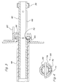
- FIG. 3 is a longitudinal sectional view taken through tubular members forming part of the wheel mounting arrangement shown in FIG. 2 .
- FIG. 4 is a sectional view taken along line 4 — 4 of FIG. 3 .
- FIG. 1 there is shown a large round baler 10 including a frame that is supported on the ground by support wheels 14 , and can be attached to a towing vehicle by a towbar 16 .
- Bale-forming rollers 18 encircle a baling chamber 20 , where the product that is collected from the ground by a pick-up or product collection apparatus 22 can be compacted into a bale.
- the baling chamber 20 comprises a front fixed housing part 24 to an upper rear location of which is mounted a rear housing part 26 for swinging between a lowered working position, as illustrated, and a raised discharge position for permitting formed round bales to be deposited on the ground.
- the pick-up 22 is supported at its opposite sides by a respective wheel 28 which holds the pick-up 22 at selected heights above the ground level, and is attached to the pickup by means of a mounting device 30 in accordance with the invention.
- the baler 10 described thus far has an appropriate construction; however, the use of the mounting device 30 in accordance with the invention is not limited to the aforementioned type of round baler in particular, nor to round balers in general. Other devices including other balers, load-bearing trailers, field choppers and combines may also be considered. Instead of being a pick-up, the collection apparatus 22 can as well be a cutting apparatus, a corn harvester, etc.
- the mounting device 30 includes a pivot bracket 32 , a holder 34 and a securing element 36 , with the pivot bracket 32 including first and second arms 38 and 40 , respectively.
- the first pivot bracket arm 38 is configured as a tube having a rectangular cross section, carrying the wheel 28 on one end and the second arm 40 on the other end.
- the first arm 38 extends perpendicular to the second arm 40 , and pivots in a vertical plane.
- the second pivot bracket arm 40 is in the form of a cylindrical pipe or rod, featuring first and second cross bores 42 and 44 , respectively, spaced lengthwise or axially along the arm 40 and having the same radial orientation relative to the central axis of the arm.
- the bores 42 and 44 are separated from one another along an adjustment path of the wheel 28 , transverse to the driving direction of the baler 10 .
- the cross bore 42 is located outboard of an inner end of the second arm 40 , while the cross bore 44 is located just inboard of the connection of the second arm 40 with the first arm 38 .
- an axially running slot 46 is located on the underside of the second arm 40 , that has a length slightly greater than the distance between the cross bores 42 and 44 .
- the holder 34 includes a cylindrical pipe 48 that, in this present case, is secured in or through a side wall of the pick-up 22 , and extends toward this side wall, which is recessed from the outer edge.
- the pipe 48 is oriented such that its central longitudinal axis extends horizontally and transverse to the driving direction of the baler and defines the pivot axis of the bracket 32 .
- the inside diameter of the pipe 48 is dimensioned to permit the second arm 40 of the pivot bracket 32 to turn with only a relatively small amount of play.
- the second arm 40 of the bracket 32 is thus telescoped within the pipe 48 and depending on the position of the bracket 32 , a more or less extensive overlap occurs between the second arm 40 and the pipe 48 .
- Holder 34 further includes a first retainer component 50 configured from sturdy sheet metal or plate in one unit that is either mounted on a side wall or other structure of the pick-up 22 , or pipe 48 .
- the component 50 features a vertical plate 52 , a horizontal crosspiece 54 projecting outwardly from and welded along a bottom part of the vertical plate 52 , and a vertical projection 56 welded to a bottom surface of the crosspiece 54 at a location spaced outwardly from a lower edge of the plate 52 , and hence an outer end of the pipe 48 .
- the plate 52 is fixed flush against the side wall of the pick-up 22 .
- the horizontal crosspiece 54 In its side opposite from that engaged with the plate 52 , the horizontal crosspiece 54 includes a square-cornered, outwardly opening cut-out or recess 58 having an inner edge disposed flush with an outer vertical surface of the projection 56 .
- the crosspiece material bounding front and rear parts of the cut-out 58 form front and rear stops 60 separated by a distance commensurate with the width of the first arm 38 of the pivot bracket 32 so that the arm 38 may be placed in the recess 58 when the wheel 28 is moved to a non-use or transport position, in a manner described below.
- Projection 56 having an upper part formed from the material removed from the crosspiece 54 to form the recess 58 , includes a bore 62 which is aligned with and the same size as the inside diameter of the pipe 48 .
- the gap from the projection 56 to the outer end of the pipe 48 is dimensioned for receiving, and preventing transverse movement of, another retainer component 64 .
- the second retainer component 64 includes a ring 66 , a keyed bolt 68 and a guide pin 70 .
- the ring 66 has an internal diameter that enables it to be slid over the second arm 40 of the pivot bracket 32 , with relatively little play, and has an outer diameter that allows it to fit between the second arm 40 and the crosspiece 54 of the first retainer component 50 and a width that permits it to be received between the end of the pipe 48 and the projection 56 .
- a bore 72 passes radially through the ring 66 and can be selectively placed in alignment with the openings 42 and 44 .
- a keyed bolt 68 is configured as a standard linchpin including a bolt 74 which can pass through the bore 72 , the bolt 74 being releasably retained in place by a semicircular spring bracket 76 can be laid on the circumferential surface of the ring 66 .
- Guide pin 70 extends radially within the inner area of the ring 66 and can engage the slot 46 in the second arm 40 in order to cause the ring 66 to be held in a fixed rotational relationship relative to the second arm 40 when the bolt 74 is removed and the arm 40 moved inward or outward relative to the ring 66 .
- guide pin 70 will be screwed into the ring 66 .
- connection 78 (see FIG. 1) is provided between the first pivot arm 38 and the pick-up 22 .
- This connection 78 securely connects the pivot bracket 32 to the pick-up 22 in at least one direction, so that the pick-up is raised if, for example, the wheel 28 rolls over a rock or the like.
- FIG. 2 The structure shown in FIG. 2 may be assembled as follows:
- Ring 66 absent the keyed bolt 68 of the linchpin, is inserted into the gap between the end of the pipe 48 and the projection 56 and aligned with the bore 62 . Then, the second arm 40 is pushed through the bore 62 , ring 66 , and into the pipe 48 . Next, the guide pin 70 is screwed or pressed in, where ring 66 is configured so that the guide pin 70 is inserted into the slot 46 of the second arm 40 . Then the bolt 74 is inserted through the cross bore 72 in the ring 66 and the cross bore 42 . This holds the pivot bracket 32 in place. Connection 78 is then placed between the pickup 22 and the bracket 32 . In this position, the wheel 28 is ready for operation and can be brought into engagement the ground by lowering the pick-up 22 .
- first connection 78 is removed and then keyed bolt 68 is removed by pivoting spring bracket 76 back and withdrawing the bolt 74 from the cross bore 42 .
- the associated bracket 32 with its first arm 38 is pivoted upwardly about the axis of the second arm 40 until the arm 38 is vertical and with the wheel 28 in an elevated position behind the front of the pick-up 22 .
- the pivot bracket 32 is pushed inward towards the side of the pick-up 22 , until the bolt 74 can be inserted into the cross bore 44 .
- the ring 66 already has the right position on the circumference of the arm 40 since the guide pin 70 is located in the guide slot 46 and prevented from turning.
- the wheel 28 comes to be positioned behind the side boundary of the tine rotor of the pick-up 22 .
- the required displacement distance depends on whether the holder 34 is mounted on, or in a recess of, the pick-up side wall, and the wheel 28 is placed on the outer side of the first arm 38 , or whether the holder 34 is on the outer wall of the pick-up and the wheel 28 is mounted on the inside of the first arm 38 .
- the first arm 38 ends up in the recess 58 between stops 60 , so that the bracket 32 and the wheel 28 are held in place even in the event of shocks. It is here noted that other arrangements of stop surfaces may be provided to place the first arm 38 in other orientations.
- a condition has be selected in which the wheel 28 is in its out-of-use position. If the wheel 28 is intended to be used when placed behind the tine rotor of the pick-up, then the first retainer component 50 and its respective recess 58 must be attached and oriented appropriately.
Landscapes
- Life Sciences & Earth Sciences (AREA)
- Environmental Sciences (AREA)
- Engineering & Computer Science (AREA)
- Mechanical Engineering (AREA)
- Soil Sciences (AREA)
- Handcart (AREA)
- Harvesting Machines For Root Crops (AREA)
- Agricultural Machines (AREA)
Applications Claiming Priority (3)
| Application Number | Priority Date | Filing Date | Title |
|---|---|---|---|
| DE10038596.6 | 2000-08-08 | ||
| DE10038596 | 2000-08-08 | ||
| DE10038596A DE10038596A1 (de) | 2000-08-08 | 2000-08-08 | Haltevorrichtung |
Publications (2)
| Publication Number | Publication Date |
|---|---|
| US20020017092A1 US20020017092A1 (en) | 2002-02-14 |
| US6553748B2 true US6553748B2 (en) | 2003-04-29 |
Family
ID=7651670
Family Applications (1)
| Application Number | Title | Priority Date | Filing Date |
|---|---|---|---|
| US09/923,022 Expired - Fee Related US6553748B2 (en) | 2000-08-08 | 2001-08-06 | Pick-up support wheel mounting arrangement |
Country Status (4)
| Country | Link |
|---|---|
| US (1) | US6553748B2 (de) |
| EP (1) | EP1179294A1 (de) |
| CA (1) | CA2354861C (de) |
| DE (1) | DE10038596A1 (de) |
Cited By (1)
| Publication number | Priority date | Publication date | Assignee | Title |
|---|---|---|---|---|
| US9433151B2 (en) | 2012-10-01 | 2016-09-06 | Chn Industrial America Llc | Caster wheel assembly of a pickup for an agricultural machine |
Families Citing this family (4)
| Publication number | Priority date | Publication date | Assignee | Title |
|---|---|---|---|---|
| BE1019354A3 (nl) * | 2010-05-31 | 2012-06-05 | Cnh Belgium Nv | Steunwiel-inrichting voor een pick-up van een landbouwmachine. |
| BE1019658A3 (nl) * | 2010-11-29 | 2012-09-04 | Cnh Belgium Nv | Pickup voor een landbouwmachine. |
| WO2021163710A1 (en) | 2020-02-14 | 2021-08-19 | Jeffrey Maichel | Insert valve and method of insertion into pressurized pipelines |
| US11892115B2 (en) | 2021-10-25 | 2024-02-06 | Jeffrey L. Maichel | Valve insertion tool |
Citations (5)
| Publication number | Priority date | Publication date | Assignee | Title |
|---|---|---|---|---|
| US3962849A (en) * | 1974-12-05 | 1976-06-15 | Hesston Corporation | Caster wheel arm |
| US4855924A (en) * | 1987-05-14 | 1989-08-08 | Ford New Holland, Inc. | Round baler with continuous bale size monitoring |
| US4945719A (en) * | 1989-09-01 | 1990-08-07 | Hay & Forage Industries | Square baler having plunger cleanout apparatus |
| WO1998017096A1 (en) | 1996-10-18 | 1998-04-30 | Hay & Forage Industries | Over-the-top support arm for pickup gauge wheel of a baler |
| FR2766322A1 (fr) | 1997-07-23 | 1999-01-29 | Claas Usines France | Equipement frontal pourvu de roues d'appui, destine a une machine agricole |
Family Cites Families (6)
| Publication number | Priority date | Publication date | Assignee | Title |
|---|---|---|---|---|
| GB752161A (en) * | 1954-07-05 | 1956-07-04 | Int Harvester Co | Improvements in or relating to agricultural machines |
| US3525537A (en) * | 1968-11-26 | 1970-08-25 | Deere & Co | Implement frame |
| US3684026A (en) * | 1971-08-13 | 1972-08-15 | Massey Ferguson Inc | Baler pick-up lift assembly |
| US4619578A (en) * | 1985-04-19 | 1986-10-28 | Routledge James H | Retractable wheel suspension apparatus |
| FR2720892B1 (fr) * | 1994-06-08 | 1996-08-30 | Bernard Galtier | Dispositif pour reployer ou déployer un groupeur de balles haute densité, grande capacité. |
| DE19710172A1 (de) * | 1997-03-12 | 1998-09-17 | Same Deutz Fahr Spa | Landwirtschaftliche Erntemaschine |
-
2000
- 2000-08-08 DE DE10038596A patent/DE10038596A1/de not_active Ceased
-
2001
- 2001-06-27 EP EP01115431A patent/EP1179294A1/de not_active Withdrawn
- 2001-08-06 US US09/923,022 patent/US6553748B2/en not_active Expired - Fee Related
- 2001-08-08 CA CA002354861A patent/CA2354861C/en not_active Expired - Fee Related
Patent Citations (6)
| Publication number | Priority date | Publication date | Assignee | Title |
|---|---|---|---|---|
| US3962849A (en) * | 1974-12-05 | 1976-06-15 | Hesston Corporation | Caster wheel arm |
| US4855924A (en) * | 1987-05-14 | 1989-08-08 | Ford New Holland, Inc. | Round baler with continuous bale size monitoring |
| US4945719A (en) * | 1989-09-01 | 1990-08-07 | Hay & Forage Industries | Square baler having plunger cleanout apparatus |
| WO1998017096A1 (en) | 1996-10-18 | 1998-04-30 | Hay & Forage Industries | Over-the-top support arm for pickup gauge wheel of a baler |
| US5819516A (en) * | 1996-10-18 | 1998-10-13 | Hay & Forage Industries | Over-the-top support arm for pickup gauge wheel of a baler |
| FR2766322A1 (fr) | 1997-07-23 | 1999-01-29 | Claas Usines France | Equipement frontal pourvu de roues d'appui, destine a une machine agricole |
Cited By (1)
| Publication number | Priority date | Publication date | Assignee | Title |
|---|---|---|---|---|
| US9433151B2 (en) | 2012-10-01 | 2016-09-06 | Chn Industrial America Llc | Caster wheel assembly of a pickup for an agricultural machine |
Also Published As
| Publication number | Publication date |
|---|---|
| CA2354861C (en) | 2005-07-12 |
| CA2354861A1 (en) | 2002-02-08 |
| EP1179294A1 (de) | 2002-02-13 |
| US20020017092A1 (en) | 2002-02-14 |
| DE10038596A1 (de) | 2002-02-21 |
Similar Documents
| Publication | Publication Date | Title |
|---|---|---|
| US7862068B2 (en) | Pin constructed for connecting a jack to an implement draft tongue and for supporting a PTO drive shaft assembly | |
| US6485045B1 (en) | Combination fifth wheel and gooseneck hitch | |
| AU736557B2 (en) | Extension coupling for use with trailers | |
| NL1005960C2 (nl) | Balenverzamelaar. | |
| US5842823A (en) | Bale-accumulating trailer | |
| US5540040A (en) | Folding hay rake | |
| US6553748B2 (en) | Pick-up support wheel mounting arrangement | |
| US6832467B2 (en) | Windrow grouper with pivotable platform | |
| US8496071B2 (en) | Implement support stand | |
| US4020913A (en) | Tongue-mounted yieldable PTO driveline support | |
| US6729637B2 (en) | Side swing hitch for an agricultural combine | |
| US7168727B2 (en) | Invertible gooseneck trailer hitch mechanism | |
| US5966912A (en) | Trailmower with angled bumper rollers | |
| CN102762092B (zh) | 一种轮组件 | |
| CA2245213C (en) | Self contained transport for crop harvesting header | |
| US4184558A (en) | Support for a PTO hookup assembly | |
| US7043892B1 (en) | Multiple baling system | |
| US10091924B2 (en) | Rear-mounted swinging tow hitch for self-propelled windrower | |
| US6367589B1 (en) | Parking lock for agricultural implement | |
| EP3939413B1 (de) | Ballenpresse | |
| EP3087826A1 (de) | Landwirtschaftliche ballenpresse mit vierteldrehung mit federbelasteter verriegelungsvorrichtung | |
| US4411571A (en) | Hay bale retrieving and transporting trailer | |
| CA2312611A1 (en) | Bale handling device | |
| US3993325A (en) | Trailer coupling apparatus | |
| US4099594A (en) | Tongue-mounted assembly for supporting an implement driveline |
Legal Events
| Date | Code | Title | Description |
|---|---|---|---|
| AS | Assignment |
Owner name: DEERE & COMPANY, ILLINOIS Free format text: ASSIGNMENT OF ASSIGNORS INTEREST;ASSIGNORS:JOSSET, ETIENNE;PAILLET, FREDERIC;UROS, RAYMOND;REEL/FRAME:012054/0438 Effective date: 20010719 |
|
| REMI | Maintenance fee reminder mailed | ||
| LAPS | Lapse for failure to pay maintenance fees | ||
| STCH | Information on status: patent discontinuation |
Free format text: PATENT EXPIRED DUE TO NONPAYMENT OF MAINTENANCE FEES UNDER 37 CFR 1.362 |
|
| FP | Lapsed due to failure to pay maintenance fee |
Effective date: 20070429 |