US6530604B1 - Coupling system with blocking device - Google Patents
Coupling system with blocking device Download PDFInfo
- Publication number
- US6530604B1 US6530604B1 US09/857,585 US85758501A US6530604B1 US 6530604 B1 US6530604 B1 US 6530604B1 US 85758501 A US85758501 A US 85758501A US 6530604 B1 US6530604 B1 US 6530604B1
- Authority
- US
- United States
- Prior art keywords
- cover
- coupling arrangement
- release
- accordance
- coupling
- Prior art date
- Legal status (The legal status is an assumption and is not a legal conclusion. Google has not performed a legal analysis and makes no representation as to the accuracy of the status listed.)
- Expired - Fee Related
Links
Images


Classifications
-
- F—MECHANICAL ENGINEERING; LIGHTING; HEATING; WEAPONS; BLASTING
- F16—ENGINEERING ELEMENTS AND UNITS; GENERAL MEASURES FOR PRODUCING AND MAINTAINING EFFECTIVE FUNCTIONING OF MACHINES OR INSTALLATIONS; THERMAL INSULATION IN GENERAL
- F16L—PIPES; JOINTS OR FITTINGS FOR PIPES; SUPPORTS FOR PIPES, CABLES OR PROTECTIVE TUBING; MEANS FOR THERMAL INSULATION IN GENERAL
- F16L37/00—Couplings of the quick-acting type
- F16L37/08—Couplings of the quick-acting type in which the connection between abutting or axially overlapping ends is maintained by locking members
- F16L37/084—Couplings of the quick-acting type in which the connection between abutting or axially overlapping ends is maintained by locking members combined with automatic locking
- F16L37/088—Couplings of the quick-acting type in which the connection between abutting or axially overlapping ends is maintained by locking members combined with automatic locking by means of a split elastic ring
- F16L37/0887—Couplings of the quick-acting type in which the connection between abutting or axially overlapping ends is maintained by locking members combined with automatic locking by means of a split elastic ring with an axially movable separate member for releasing the coupling
-
- F—MECHANICAL ENGINEERING; LIGHTING; HEATING; WEAPONS; BLASTING
- F16—ENGINEERING ELEMENTS AND UNITS; GENERAL MEASURES FOR PRODUCING AND MAINTAINING EFFECTIVE FUNCTIONING OF MACHINES OR INSTALLATIONS; THERMAL INSULATION IN GENERAL
- F16L—PIPES; JOINTS OR FITTINGS FOR PIPES; SUPPORTS FOR PIPES, CABLES OR PROTECTIVE TUBING; MEANS FOR THERMAL INSULATION IN GENERAL
- F16L2201/00—Special arrangements for pipe couplings
- F16L2201/20—Safety or protective couplings
Definitions
- the invention herein relates to a coupling arrangement for connecting two elements, said arrangement comprising a plug element and a bushing element which can be connected with each other and locked together by means of an expandable retaining ring.
- the problem to be solved by the invention herein is to provide a coupling arrangement which features a simple design and, in addition, can be taken apart easily without the use of tools.
- a coupling arrangement having a release arrangement with a blocking device.
- This coupling arrangement is characterized in that the release arrangement comprises a release sleeve, which, on its side facing away from the bushing element, can be closed with a cover and that the inadvertent release of the coupling can be prevented with the use of a blocking device.
- the cover acts as a release tool being an integral part of the coupling arrangement, whereby said tool can be moved advantageously by applying pressure (e.g., the user's thumb) to said cover.
- the force required by the user to release the locking mechanism is only very small, whereby, due to the relatively large surface area are of the cover—which preferably has a closed cover bottom—available for the application of pressure, great ease of use is ensured while pressure is being applied.
- the blocking device ensures that eh coupling cannot be released inadvertently, for example, due to the impact of a stone.
- the cover is part of the blocking device and can be moved into a locked position and in into actuation position.
- the locked position does not allow the non-destructive release of the coupling.
- the cover must first be moved into the actuation position, preferably by pivoting motion, so that the locking mechanism may be released. Therefore, the cover performs a dual function: on one hand it is used, together with the release sleeve, as a release tool for releasing the locking mechanism and on the other hand as a securing element offering protection against the inadvertent release of the locking mechanism.
- the cover is retained on the release sleeve with the use of a snap connection that is preferably “not releasable.”
- “not releasable” is understood to mean that, upon affixing the cover to the release sleeve, said cover can no longer be removed without damaging it or another part of the coupling arrangement.
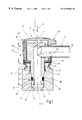
- FIG. 1 a cross-section of a first example of embodiment of the coupling arrangement
- FIGS. 2A and 2B side elevations of an example of embodiment of the cover
- FIG. 3 a cross-section of the cover in accordance with FIG. 2A and 2B;
- FIGS. 4A and 4B a view of the underside and a view of the top of the cover shown in FIG. 2A and 2B;
- FIG. 4C a plan view of another form of embodiment of the cover
- FIG. 5 a sectional view, greatly enlarged, of a part of the cover marked “B” in FIG. 3;
- FIG. 6 a perspective illustration of an example of embodiment in coupled state, whereby the cover is in locked position
- FIGS. 7A and 7B side elevations of the coupling arrangement shown in FIG. 6;
- FIG. 8 a perspective illustration of the coupling arrangement shown in FIG. 6, whereby the cover is in actuation position
- FIGS. 9A and 9B side elevations of the coupling arrangement shown in FIG. 8 .
- FIG. 1 shows a cross-section of an example of embodiment of a coupling arrangement 1 , a plug element 3 and a bushing element 5 .
- the bushing element is configured in a rotation-symmetrical manner.
- Plug element 3 has a pocket bore 7 extending parallel to central longitudinal axis 9 of plug element 3 .
- the base area of pocket bore 7 is provided with a transverse bore 13 terminating in said pocket bore, said pocket bore accommodating the end of pipe 11 .
- a hose or the like may be connected with plug element 3 in a suitable manner.
- Pipe 11 connected with plug element 3 is aligned with respect to plug element 3 in such a manner that central longitudinal axis 15 of pipe 11 extends in orthogonal direction with respect to central longitudinal axis 9 of plug element 3 .
- Plug element 3 comprises a first rotation-symmetrical longitudinal section 17 with a larger-diameter portion created here by a peripheral bead 19 . Furthermore, plug element 3 has a second rotation-symmetrical longitudinal section 21 , the function of which will be described later in detail.
- Bushing element 5 which, in the example of embodiment herein has a tubular configuration, may itself be connected with a pipe, a hose or the like.
- bushing element 5 in a connection box for direct connection of the plug element with any other module, for example a pump, a container or the like.
- One wall 23 of bushing element 5 encloses an interior space 25 having circular cross-section, said space being designed for the accommodation of longitudinal section 17 of plug element 3 .
- Exterior side 26 of plug element 3 has a peripheral groove 29 in the region of the first longitudinal element 17 , whereby—viewed in longitudinal direction of plug element 3 —said groove 29 is located at a distance from a peripheral groove 31 on interior wall 27 of bushing element 5 .
- the distances of grooves 29 , 31 from axis of rotation 32 of bushing element 5 are different.
- axis of rotation 32 of bushing element 5 and central longitudinal axis 9 of plug element 3 coincide at this point.
- a retaining ring 33 is provided, whereby said ring abuts against a surface of groove 31 extending in a direction diagonal to axis of rotation 32 .
- Retaining ring 33 is configured in such a manner that its diameter can be expanded.
- a retaining ring 33 which can be split at a point, a so-called spring ring, is used.
- the diameter of retaining ring 33 is selected slightly greater than the inside diameter of interior space 25 .
- a sealing means 37 is provided, said sealing means consists of an O-ring 38 and a bearing ring 39 located in groove 29 of plug element 3 in this example of embodiment. Bearing ring 39 is used to support O-ring 38 , when pressure is applied. Sealing means 37 seals the gap between bushing element 5 and plug element 3 .
- coupling arrangement 1 comprises a release arrangement 41 with a release sleeve 43 .
- Release sleeve 43 has a tubular first longitudinal section 45 and a cup-shaped second longitudinal section 47 that are connected with each other to form one piece.
- the outside diameter in the region of the second longitudinal section 47 is greater than that in the region of the first longitudinal section 45 , thereby forming a peripheral collar.
- Plug element 3 is inserted in release sleeve 43 in such a manner that its first longitudinal section 17 having the smaller diameter is supported, essentially without play and movable in longitudinal direction, in the region of the first longitudinal section 45 of release sleeve 43 . This is accomplished in that the inside diameter of the first longitudinal section 45 of release sleeve 43 has essentially the same size as the outside diameter of the first longitudinal section 17 of plug element 3 .
- the second longitudinal section 21 of plug element 3 is located inside release sleeve 43 , i.e., it is completely enclosed by jacket 48 of release sleeve 43 , and abuts against bottom 49 of the cup-shaped second longitudinal section 47 of release sleeve 43 , while the first longitudinal section 17 of plug element 3 is inserted through an opening provided in bottom 49 .
- the height of the second longitudinal section 21 of plug element 3 is smaller than that of the second longitudinal section 47 of release sleeve 43 , so that this part of plug element 3 is enclosed completely by the wall of release sleeve 43 .
- longitudinal section 47 of release sleeve 43 has an opening 50 into which pipe 11 is inserted.
- Angle ⁇ which is within a range of 0° ⁇ 180°, is variable.
- coupling arrangement 1 is characterized in that the parts to be connected (module, pump, container or the like) need not to be in alignment.
- release sleeve 43 On its side facing away from plug element 5 , release sleeve 43 is closed with a cover 51 having a peripheral collar 53 extending over a circular region of longitudinal section 47 of release sleeve 43 .
- Cover 51 is part of a blocking device 55 , which will be discussed in detail hereinafter.
- a snap connection 57 preferably non-releasable, is used for connecting cover 51 with release sleeve 43 ; this means, once cover 51 has been mounted, it can no longer be removed from release sleeve 43 in a non-destructive manner. Consequently, the loss of the cover can be prevented with certainty.
- snap closure 57 is created by a peripheral groove provided on the outside of jacket 48 of the second longitudinal section 47 of release sleeve 43 and a projection 59 (FIG. 5) on the inside of collar 53 of cover 51 .
- Projection 59 comes into engagement with the groove on jacket 48 in such a manner that a removal of cover 51 from release sleeve 43 is not possible.
- Projection 59 and the groove are adapted to each other in such a manner that, with projection 59 engaged, cover 51 can still be pivoted about its central axis 61 in clockwise as well as counterclockwise direction. By pivoting, cover 51 can be moved into a locked position, in which the locking mechanism cannot be released, and into an actuation position, in which the locking mechanism can be released.
- FIG. 2A and 2B shows a side elevation of cover 51 , which, in this example of embodiment, has a wavy surface created by vertically extending recesses on the outside of collar 53 —viewed in peripheral direction of collar 53 —said surface making it easier to grip cover 51 more firmly.
- the inside of cover 51 has a stop element 63 which is connected with cover 51 so as to form one piece with said cover.
- Stop element 63 consists of a wall 65 , which extends over a small peripheral area of cover 51 having an essentially circular form when viewed from the top.
- said wall consists of a material exhibiting certain elasticity.
- wall 65 abuts against the external contour of a counter-element or it is arranged at a distance from such a counter-element.
- Abutment surface 67 of wall 65 preferably is adapted to the external contour of the counter-element.
- said counter-element is configured as the pipe 11 . Therefore, abutment surface 67 of stop element 63 has a curved, preferably arcuate, shape.
- cover 51 has an essentially circular form in the region of its second longitudinal section 47 to correspond with the cross-sectional form of the release sleeve in the region of its second longitudinal section 47 .
- the upper side of the cover (FIG. 4B) is stamped with a large “P” to indicate to the user that a pressure-type connection exists at this point.
- cover 51 has a projection 69 , which extends from the external peripheral surface of cover 51 , i.e., collar 53 , and, in this example of embodiment is configured as a nose when cover 51 is viewed from.the top.
- projection 69 is used as an indicating means 71 for a user. With cover 51 is mounted, a first position of projection 69 relative to said pipe corresponds to the locked position and a second relative position corresponds to the actuation position.
- Numbers “0” and “I” provided on the upper side of cover 51 are arranged in peripheral direction of said cover at an angular distance of approximately 45°. Number “0” is located at the height of projection 69 and number “I” is offset in peripheral direction with respect to the latter.
- FIG. 3 depicts a cross-section of cover 51 along line A—A of FIG. 4 and shows that stop element 63 being an integral part of the cover's bottom is located on the same height as projection 69 and radially offset toward the inside, when viewed in peripheral direction of cover 51 .
- FIG. 4C shows a plan view of another example of embodiment of cover 51 , which differs from the cover shown in FIG. 4B only in that it has a company logo applied to the cover's upper side instead of a large “P.”
- indicating means 71 in this example of embodiment consists of projection 69 as well as the phrase “OPEN” and an arrow indicating the cover's direction of rotation.
- a sealing element 75 is provided on the end side 73 of release sleeve 43 facing bushing element 5 , said sealing element acting as protection against dirt and being configured as a circular axial sealing lip 77 coming into engagement with an open-edge recess on the outside of the second longitudinal section 47 of release sleeve 43 .
- Sealing element 75 prevents the penetration of dirt into the space between release sleeve 43 and bushing element 5 , or the component—e.g., a module—comprising bushing element 5 .
- bushing element 75 described with reference to FIG. 1 may be placed on end side 73 of release sleeve 43 facing bushing element 5 , or on the outside or inside of release sleeve 43 .
- FIG. 6 and FIG. 8 shows a perspective illustration of coupling arrangement 1 , whereby cover 51 is depicted in locked position in FIG. 6 and in actuation position in FIG. 8 .
- FIG. 7 A and FIG. 7B shows—in association with FIG. 6 —a side elevation, partially in section, of coupling arrangement 1 ; and each of FIG. 9A and 9B shows a side elevation, partially in section, of coupling arrangement 1 as shown by FIG. 8 .
- the same parts have the same reference numbers; therefore, reference is made to the description of the previously used figures.
- bushing element 5 is connected with a module 81 (shown in longitudinal section) in order to form one piece, i.e., in order to be an integral part of said module.
- FIGS. 6, 7 A and 7 B respectively, show cover 51 pivoted into its first position, the locked position, in which.projection 69 on cover 51 is located above pipe 11 .
- Stop element 63 of blocking arrangement 55 is also located above pipe 11 and its wall 65 is supported by the external contour of pipe 11 (FIG. 7 B). Consequently, abutment surface 67 of stop element 63 abuts against the outside of pipe 11 .
- stop element 63 is in locked position of cover 51 at a—preferably small—distance from pipe 11 .
- stop element 63 cooperating with pipe 11 prevents a shifting of release sleeve 43 in the direction of retaining ring 33 in such a manner that the release of the locking mechanism is prevented.
- cover 51 is pivoted, with respect to its position shown in FIG. 6, in counterclockwise manner about its central axis 61 by a quarter turn into the actuation position, in which projection 69 of cover 51 —when cover 51 is viewed from the top—is located on the side of pipe 11 .
- release sleeve 43 is pressed in downward direction following arrow 79 (FIG. 1 )
- stop element 63 does not abut against pipe 11 , but passes through it in lateral direction.
- release sleeve 43 can be pushed downward in vertical direction until the locking mechanism releases.
- release arrangement 41 and blocking device 55 of coupling arrangement 1 are described in greater detail:
- FIG. 1 shows coupling arrangement 1 in coupled state.
- the free end of longitudinal section 45 of release sleeve 43 is located directly on retaining ring 33 and, when pressure is applied to cover 51 in axial direction, comes into contact with retaining ring 33 in order to transmit the axial force to retaining ring 33 .
- the outside diameter of longitudinal section 45 of release sleeve 43 is selected in such a manner that said section can be moved and guided—with slight radial play—in axial direction through the inside wall 27 of bushing element 5 .
- Sealing lip 77 consists of an elastic material so that release sleeve 43 may be pressed in axial direction onto bushing element 5 . At the same time, due to its elasticity, sealing lip 77 ensures that release sleeve 43 and hence plug element 3 are subjected to a force acting against the direction of insertion, whereby retaining ring 33 is clamped between the portion having the greater diameter (bead 19 ) of the first longitudinal section 17 and area 35 of internal wall 27 . Consequently, coupling arrangement 1 is locked in position.
- cover 51 shown in a locked position in FIG. 6 is pivoted in a counterclockwise manner about its central axis into the actuation position shown in FIG. 8 .
- stop element 63 viewed in axial direction of plug element 3 —is offset with respect to pipe 11 so that, if pressure is applied to cover 51 in the direction of bushing element 5 (arrow 79 ), release sleeve 43 is moved in axial direction and pressed against retaining ring 33 .
- retaining 33 is forced into groove 31 in bushing element 5 , whereby the coupling's locking mechanism is released and plug element 3 can be pulled out of bushing element 5 .
- Release sleeve 43 is preferably produced by injection-molding and may consist of metal and/or plastic material. Release sleeve 43 shown in the drawings has in its jacket surface at least one opening 83 (FIG. 7 A and FIG. 9A) which improves the handling ability of release sleeve 43 and permits removal of heavy dirt, for example, and, which the use of a pressurized steam cleaner. Of course, in another form of embodiment of said release sleeve its jacket surface may be closed, i.e., not be provided with an opening.
- sealing element 75 as well as sealing means 37 remain in release sleeve 43 or on plug element 3 . Consequently, the design of bushing element 5 can be simplified. Moreover, it is possible to exchange sealing element 75 and/or sealing means 37 during each coupling operation.
- Blocking device 55 may be designed in any manner; for example, the counter-element cooperating with stop element 63 may be an integral part of the component comprising the bushing element. Important is that the blocking device permits a simple move of cover 51 into the locked or actuation position and is preferably easy to manufacture.
- the blocking device may also be configured in such a manner that it cooperates directly with release sleeve 43 , whereby, in this case, its cover is used as a cover for said release sleeve's end facing away from the bushing element and as an actuation element for the release of the locking mechanism.
- a seal in particular a flat seal, is interposed between the second longitudinal section 21 of plug element 3 and bottom 49 of release sleeve 43 in order to prevent the penetration of dirt in the gap between said plug element and said release sleeve.
- this flat seal acts as abutment surface for the plug element.
- coupling arrangement 1 may be associated with at least one indicating element, which indicates the connection of both coupling elements (bushing element/plug element).
Applications Claiming Priority (5)
| Application Number | Priority Date | Filing Date | Title |
|---|---|---|---|
| DE19857144 | 1998-12-11 | ||
| DE19857144A DE19857144C2 (de) | 1998-12-11 | 1998-12-11 | Kupplungseinrichtung |
| DE19931753 | 1999-07-08 | ||
| DE19931753A DE19931753C2 (de) | 1998-12-11 | 1999-07-08 | Kupplungseinrichtung mit Blockiervorrichtung |
| PCT/EP1999/008293 WO2000036328A1 (de) | 1998-12-11 | 1999-10-30 | Kupplungseinrichtung mit blockiervorrichtung |
Publications (1)
| Publication Number | Publication Date |
|---|---|
| US6530604B1 true US6530604B1 (en) | 2003-03-11 |
Family
ID=26050695
Family Applications (1)
| Application Number | Title | Priority Date | Filing Date |
|---|---|---|---|
| US09/857,585 Expired - Fee Related US6530604B1 (en) | 1998-12-11 | 1999-10-30 | Coupling system with blocking device |
Country Status (4)
| Country | Link |
|---|---|
| US (1) | US6530604B1 (de) |
| EP (1) | EP1137893B1 (de) |
| ES (1) | ES2181508T3 (de) |
| WO (1) | WO2000036328A1 (de) |
Cited By (13)
| Publication number | Priority date | Publication date | Assignee | Title |
|---|---|---|---|---|
| US20030062721A1 (en) * | 2001-09-28 | 2003-04-03 | Masayoshi Usui | Ring joint, connection structure for connecting piping and ring joint, and method of connecting ring joint and piping |
| US20050161938A1 (en) * | 2004-01-27 | 2005-07-28 | Dahms Jason W. | Coupling assembly with latching sleeve |
| US20050167979A1 (en) * | 2004-02-02 | 2005-08-04 | Dahms Jason W. | Coupling assembly |
| US20060208484A1 (en) * | 2005-03-11 | 2006-09-21 | Swift Jonathan C | Quick connect coupling with disconnect lock |
| US20070001450A1 (en) * | 2005-03-11 | 2007-01-04 | Swift Jonathan C | Pressure activated disconnect lock coupling |
| US20070052237A1 (en) * | 2004-07-21 | 2007-03-08 | Andreas Udhofer | Adaptor and method for converting standard tube fitting/port to push-to-connect tube fitting/port |
| US20080136178A1 (en) * | 2004-07-21 | 2008-06-12 | Parker-Hannifin Corporation | Adaptor and Method For Converting Standard Tube Fitting/Port to Push-To-Connect Tube Fitting/Port |
| US20090267341A1 (en) * | 2008-04-24 | 2009-10-29 | Telsco Industries, Inc. | Hexpipe barbed fitting |
| US20110012350A1 (en) * | 2008-03-05 | 2011-01-20 | Camozzi S.P.A. Societa' Unipersonale | Fitting with a Security Ring |
| US20110057437A1 (en) * | 2004-09-17 | 2011-03-10 | The Gates Corporation | Quick Connect Coupling Stabilization Apparatus, Systems and Methods |
| US20120228271A1 (en) * | 2009-09-11 | 2012-09-13 | Fronius International Gmbh | Hose assembly and coupling device for a welding device |
| US20180216766A1 (en) * | 2017-02-02 | 2018-08-02 | North American Pipe Corporation | System for conduit squeeze retainer |
| US11098834B2 (en) | 2017-09-18 | 2021-08-24 | North American Pipe Corporation | System, method and apparatus for debris shield for squeeze-activated retainer for a conduit |
Families Citing this family (1)
| Publication number | Priority date | Publication date | Assignee | Title |
|---|---|---|---|---|
| DE202008007062U1 (de) * | 2008-05-26 | 2009-10-01 | Voss Fluid Gmbh | Steckverbindung für Fluid-Leitungen |
Citations (6)
| Publication number | Priority date | Publication date | Assignee | Title |
|---|---|---|---|---|
| US5226682A (en) | 1992-07-21 | 1993-07-13 | Aeroquip Corporation | Coupling assembly |
| US5553895A (en) * | 1995-05-03 | 1996-09-10 | Aeroquip Corporation | Coupling assembly |
| US5570910A (en) | 1995-08-18 | 1996-11-05 | Aeroquip Corporation | Coupling assembly |
| EP0757201A1 (de) | 1995-08-04 | 1997-02-05 | Smiths Industries Public Limited Company | Fluidkupplung |
| DE29680971U1 (de) | 1995-10-30 | 1998-11-05 | Manuli Auto France | Fluiddichte Schnellverbindung |
| US6186557B1 (en) * | 1998-02-24 | 2001-02-13 | Johannes Schafer Vorm. Stettiner Schrauben Werke Gmbh & Co. Kg | Pipe connection and combination of a connection and a detaching tool |
Family Cites Families (1)
| Publication number | Priority date | Publication date | Assignee | Title |
|---|---|---|---|---|
| US5374089A (en) * | 1992-09-29 | 1994-12-20 | Itt Industries Inc. | High pressure quick connector |
-
1999
- 1999-10-30 ES ES99973427T patent/ES2181508T3/es not_active Expired - Lifetime
- 1999-10-30 EP EP99973427A patent/EP1137893B1/de not_active Expired - Lifetime
- 1999-10-30 WO PCT/EP1999/008293 patent/WO2000036328A1/de active IP Right Grant
- 1999-10-30 US US09/857,585 patent/US6530604B1/en not_active Expired - Fee Related
Patent Citations (6)
| Publication number | Priority date | Publication date | Assignee | Title |
|---|---|---|---|---|
| US5226682A (en) | 1992-07-21 | 1993-07-13 | Aeroquip Corporation | Coupling assembly |
| US5553895A (en) * | 1995-05-03 | 1996-09-10 | Aeroquip Corporation | Coupling assembly |
| EP0757201A1 (de) | 1995-08-04 | 1997-02-05 | Smiths Industries Public Limited Company | Fluidkupplung |
| US5570910A (en) | 1995-08-18 | 1996-11-05 | Aeroquip Corporation | Coupling assembly |
| DE29680971U1 (de) | 1995-10-30 | 1998-11-05 | Manuli Auto France | Fluiddichte Schnellverbindung |
| US6186557B1 (en) * | 1998-02-24 | 2001-02-13 | Johannes Schafer Vorm. Stettiner Schrauben Werke Gmbh & Co. Kg | Pipe connection and combination of a connection and a detaching tool |
Cited By (24)
| Publication number | Priority date | Publication date | Assignee | Title |
|---|---|---|---|---|
| US6851723B2 (en) * | 2001-09-28 | 2005-02-08 | Usui Kokusai Sangyo Kaisha, Ltd. | Ring joint, connection structure for connecting piping and ring joint, and method of connecting ring joint and piping |
| US20030062721A1 (en) * | 2001-09-28 | 2003-04-03 | Masayoshi Usui | Ring joint, connection structure for connecting piping and ring joint, and method of connecting ring joint and piping |
| US20050161938A1 (en) * | 2004-01-27 | 2005-07-28 | Dahms Jason W. | Coupling assembly with latching sleeve |
| US7543854B2 (en) | 2004-01-27 | 2009-06-09 | Eaton Corporation | Coupling assembly with latching sleeve |
| US7488006B2 (en) | 2004-02-02 | 2009-02-10 | Eaton Corporation | Coupling assembly |
| US20050167979A1 (en) * | 2004-02-02 | 2005-08-04 | Dahms Jason W. | Coupling assembly |
| US8240719B2 (en) | 2004-07-21 | 2012-08-14 | Parker-Hannifin Corporation | Adaptor and method for converting standard tube fitting/port to push-to-connect tube fitting/port |
| US20070052237A1 (en) * | 2004-07-21 | 2007-03-08 | Andreas Udhofer | Adaptor and method for converting standard tube fitting/port to push-to-connect tube fitting/port |
| US7914050B2 (en) | 2004-07-21 | 2011-03-29 | Parker-Hannifin Corporation | Adaptor and method for converting standard tube fitting/port to push-to-connect tube fitting/port |
| US20080136178A1 (en) * | 2004-07-21 | 2008-06-12 | Parker-Hannifin Corporation | Adaptor and Method For Converting Standard Tube Fitting/Port to Push-To-Connect Tube Fitting/Port |
| US20110057437A1 (en) * | 2004-09-17 | 2011-03-10 | The Gates Corporation | Quick Connect Coupling Stabilization Apparatus, Systems and Methods |
| US8028392B2 (en) | 2004-09-17 | 2011-10-04 | The Gates Corporation | Method of joining and disjoining fluid passages |
| US20070001450A1 (en) * | 2005-03-11 | 2007-01-04 | Swift Jonathan C | Pressure activated disconnect lock coupling |
| US7533907B2 (en) | 2005-03-11 | 2009-05-19 | The Gates Corporation Ip Law Dept. | Pressure activated disconnect lock coupling |
| US7469933B2 (en) | 2005-03-11 | 2008-12-30 | The Gates Corporation | Quick connect coupling with disconnect lock |
| US20060208484A1 (en) * | 2005-03-11 | 2006-09-21 | Swift Jonathan C | Quick connect coupling with disconnect lock |
| US20110012350A1 (en) * | 2008-03-05 | 2011-01-20 | Camozzi S.P.A. Societa' Unipersonale | Fitting with a Security Ring |
| US7717475B2 (en) * | 2008-04-24 | 2010-05-18 | Telsco, Industries, Inc. | Hexpipe barbed fitting |
| US20090267341A1 (en) * | 2008-04-24 | 2009-10-29 | Telsco Industries, Inc. | Hexpipe barbed fitting |
| US20120228271A1 (en) * | 2009-09-11 | 2012-09-13 | Fronius International Gmbh | Hose assembly and coupling device for a welding device |
| US9643278B2 (en) * | 2009-09-11 | 2017-05-09 | Fronius International Gmbh | Hose assembly and coupling device for a welding device |
| US20180216766A1 (en) * | 2017-02-02 | 2018-08-02 | North American Pipe Corporation | System for conduit squeeze retainer |
| US10550979B2 (en) * | 2017-02-02 | 2020-02-04 | North American Pipe Corporation | System for conduit squeeze retainer |
| US11098834B2 (en) | 2017-09-18 | 2021-08-24 | North American Pipe Corporation | System, method and apparatus for debris shield for squeeze-activated retainer for a conduit |
Also Published As
| Publication number | Publication date |
|---|---|
| ES2181508T3 (es) | 2003-02-16 |
| EP1137893A1 (de) | 2001-10-04 |
| EP1137893B1 (de) | 2002-08-14 |
| WO2000036328A1 (de) | 2000-06-22 |
Similar Documents
| Publication | Publication Date | Title |
|---|---|---|
| US6530604B1 (en) | Coupling system with blocking device | |
| ES2346690T3 (es) | Conector enchufable para tuberias de medios. | |
| US6199920B1 (en) | Connecting piece for profiled pipes, profiled nipples, corrugated tubes or the like elongate articles | |
| US5511827A (en) | Push-fit connector for joining two fluid lines | |
| US6173998B1 (en) | Plug-in coupling for connecting two fluid conduits | |
| US5971019A (en) | Mismating-free connector assembly | |
| US9377144B2 (en) | Release tool for quick connector | |
| JPH0439492A (ja) | クイックコネクタ | |
| US10487968B2 (en) | Locking fluid connector | |
| JPH07151278A (ja) | 波形管用継手 | |
| US6422267B1 (en) | Pipe coupling | |
| US6170887B1 (en) | Plug connector for rapid and releaseable connection of pressurized lines | |
| US20030111136A1 (en) | Compressed-gas canister for a fastening appliance and adapter cap for fitting an intermediate seal | |
| US4111470A (en) | Releasable coupling and method for making such coupling | |
| FR2599184A2 (fr) | Element d'actionnement pouvant ete accouple a un appareil de commutation | |
| AU2003203472B2 (en) | Coupling for compressed gas piston driven nailing and fuel cartridge | |
| JP5107233B2 (ja) | リリースクリップ | |
| US20020053797A1 (en) | Quick coupling for hoses and pipelines with increased diffusion resistance | |
| EP0555981B1 (de) | Verbesserungen an Rohrverbindungen | |
| EP0877192A2 (de) | Kupplung | |
| CA1043719A (en) | Universal dust cover for a hydraulic coupling socket | |
| EP1039206A3 (de) | Schlauchverbindung | |
| US11291823B2 (en) | Coupling component and fluid coupling | |
| JPS6028863Y2 (ja) | ガスホ−ス接続具 | |
| JP7474424B2 (ja) | 継手 |
Legal Events
| Date | Code | Title | Description |
|---|---|---|---|
| AS | Assignment |
Owner name: AEROQUIP-VICKERS INTERNATIONAL GMBH, GERMANY Free format text: ASSIGNMENT OF ASSIGNORS INTEREST;ASSIGNORS:STUMPF, ROBERT;SCHMID, JOHANNES;LUFT, THOMAS;REEL/FRAME:012133/0571;SIGNING DATES FROM 20010723 TO 20010813 |
|
| FPAY | Fee payment |
Year of fee payment: 4 |
|
| FPAY | Fee payment |
Year of fee payment: 8 |
|
| REMI | Maintenance fee reminder mailed | ||
| LAPS | Lapse for failure to pay maintenance fees | ||
| STCH | Information on status: patent discontinuation |
Free format text: PATENT EXPIRED DUE TO NONPAYMENT OF MAINTENANCE FEES UNDER 37 CFR 1.362 |
|
| FP | Lapsed due to failure to pay maintenance fee |
Effective date: 20150311 |