US6507315B2 - System and method for efficiently characterizing the elements in an array antenna - Google Patents
System and method for efficiently characterizing the elements in an array antenna Download PDFInfo
- Publication number
- US6507315B2 US6507315B2 US09/848,063 US84806301A US6507315B2 US 6507315 B2 US6507315 B2 US 6507315B2 US 84806301 A US84806301 A US 84806301A US 6507315 B2 US6507315 B2 US 6507315B2
- Authority
- US
- United States
- Prior art keywords
- antenna
- probe
- array antenna
- values
- signals
- Prior art date
- Legal status (The legal status is an assumption and is not a legal conclusion. Google has not performed a legal analysis and makes no representation as to the accuracy of the status listed.)
- Expired - Lifetime
Links
- 238000000034 method Methods 0.000 title claims abstract description 109
- 239000000523 sample Substances 0.000 claims abstract description 228
- 238000005259 measurement Methods 0.000 claims abstract description 58
- 230000008878 coupling Effects 0.000 claims description 27
- 238000010168 coupling process Methods 0.000 claims description 27
- 238000005859 coupling reaction Methods 0.000 claims description 27
- 230000001427 coherent effect Effects 0.000 claims description 18
- 238000012545 processing Methods 0.000 claims description 16
- 238000012512 characterization method Methods 0.000 claims description 15
- 230000010363 phase shift Effects 0.000 claims description 14
- 238000012883 sequential measurement Methods 0.000 abstract description 5
- 238000012360 testing method Methods 0.000 description 22
- 230000008569 process Effects 0.000 description 19
- 238000010586 diagram Methods 0.000 description 7
- 230000005855 radiation Effects 0.000 description 5
- 238000013459 approach Methods 0.000 description 4
- 238000013461 design Methods 0.000 description 4
- 108091026890 Coding region Proteins 0.000 description 3
- 238000010420 art technique Methods 0.000 description 3
- 230000005540 biological transmission Effects 0.000 description 3
- 238000004891 communication Methods 0.000 description 3
- 238000012937 correction Methods 0.000 description 3
- 239000002131 composite material Substances 0.000 description 2
- 230000006872 improvement Effects 0.000 description 2
- 230000010354 integration Effects 0.000 description 2
- 230000003993 interaction Effects 0.000 description 2
- 238000000691 measurement method Methods 0.000 description 2
- 238000004886 process control Methods 0.000 description 2
- 238000000926 separation method Methods 0.000 description 2
- 230000001360 synchronised effect Effects 0.000 description 2
- 241000272168 Laridae Species 0.000 description 1
- 230000002411 adverse Effects 0.000 description 1
- 238000004458 analytical method Methods 0.000 description 1
- 238000003491 array Methods 0.000 description 1
- 238000004364 calculation method Methods 0.000 description 1
- 238000005516 engineering process Methods 0.000 description 1
- 238000002955 isolation Methods 0.000 description 1
- 239000011159 matrix material Substances 0.000 description 1
Images


Classifications
-
- H—ELECTRICITY
- H01—ELECTRIC ELEMENTS
- H01Q—ANTENNAS, i.e. RADIO AERIALS
- H01Q3/00—Arrangements for changing or varying the orientation or the shape of the directional pattern of the waves radiated from an antenna or antenna system
- H01Q3/26—Arrangements for changing or varying the orientation or the shape of the directional pattern of the waves radiated from an antenna or antenna system varying the relative phase or relative amplitude of energisation between two or more active radiating elements; varying the distribution of energy across a radiating aperture
- H01Q3/267—Phased-array testing or checking devices
-
- H—ELECTRICITY
- H01—ELECTRIC ELEMENTS
- H01Q—ANTENNAS, i.e. RADIO AERIALS
- H01Q25/00—Antennas or antenna systems providing at least two radiating patterns
Definitions
- the present invention relates to array antennas and more specifically to characterization of element patterns and amplifier characteristics in array antennas.
- an “active element” immersed in an array environment will behave differently from the case where the antenna element is removed from the array. This problem arises from mutual coupling between the antenna elements. Therefore if one is to have an accurate model for predicting its performance, the antenna element must be measured when the antenna element is placed in the array environment. In the prior art, the process is typically done by applying a source to the “active element,” terminating the rest of the array elements, and then measuring the given active antenna element pattern.
- single element pattern characterization measurements are used to determine each of the antenna element patterns. For an array of N elements, this is accomplished by exciting one array element and terminating all other N ⁇ 1 array elements, such that only the desired array element is radiating energy. Only one of N array elements is measured at a time. Therefore, this is called the single antenna element approach. Using the single antenna element approach, all N antenna elements are measured sequentially. This process can be used to measure any array element pattern with the array element immersed in the array environment, which is, in general, different from an isolated array element, thus accounting for the mutual coupling interactions among array elements.
- a problem with the prior art approach is that it is very time consuming since antenna elements are measured sequentially and the positioner will be required to go through the desired movement cycle once for each active array element. This is extremely inefficient and impractical when the positioner movement and data acquisition cycle must be repeated N times.
- a second disadvantage is that, in some cases, it may be difficult, impractical, or impossible to shut off all but one array element in the array under test. Removing signals from all but one array element may become a time consuming and expensive process, involving removal of a cable and replacement with a termination. If one is to rely on turning antenna elements off using digitally controlled radio frequency (RF) on/off switches, RF isolation may not be sufficient to allow for measurements to be performed to a suitable level of accuracy.
- RF radio frequency
- the characterization of the amplitude and phase of each antenna element against signal level, frequency, and ambient temperature is crucial to create “look-up” calibration tables. This is particularly important in multi-beam active array antennas to characterize the nonlinear behavior of the amplifiers, and to compare them with theoretical models such as the Shimbo model; see O. Shimbo, “Transmission Analysis in Communication Systems,” Computer Science Press (1988).
- the current technique is to characterize each antenna element one at a time by disconnecting, turning off, or attenuating the other elements in the array. This is again the single antenna element approach so the technique is very time consuming, and therefore results in high parts integration and test time, which in turn adversely impacts the total assembly costs.
- active phased-array antennas typically have a requirement to determine array element patterns while the antenna element is in the array environment. These data are needed for scaling factor constants which take into account that the antenna elements are at different distances from the calibration probe.
- the scaling factor constants are used in the near-field calibration system described in U.S. Pat. No. 6,084,545, issued Jul. 4, 2000 in the name of Lier et al. to take control circuit encoding (CCE) measurements of each of the array elements in an array antenna; see U.S. Pat. No. 5,572,219, issued Nov. 5, 1996 in the name of Silverstein et al.
- the system and method of the present invention described herein discloses a positioning device which allows movement of the antenna with respect to a calibration probe or movement of the calibration probe with respect to the antenna. It is the intermittent movement of the antenna and probe with respect to each other between measurement cycles which significantly improves implementation of the calibration procedure by permitting multiple simultaneous control circuit encoding (CCE) measurements of each of the array elements in an array antenna.
- CCE control circuit encoding
- the system and method of the present invention described herein discloses changes in the level of signals transmitted by the amplifiers in the elements of an array antenna system in conjunction with the use of orthogonal coding measurements. Changes in the level of signals transmitted significantly improves implementation of the process of determining amplifier characteristics by permitting simultaneous measurement of the amplifier characteristics of each of the array elements in an array antenna.
- the present invention comprises a system for characterizing the patterns of a plurality of elements located in an array antenna, with each of the plurality of elements including at least one of (either or both) a phase shifter and an amplitude attenuator.
- the antenna includes a signal port for each individual beam which the array antenna generates, and a control signal input port to which control signals are applied for control of the phase shifters and amplitude attenuators.
- a plurality of antenna elements comprise a beamformer, a plurality of beamformers form the array antenna.
- the system for characterizing the patterns of a plurality of elements located in the array antenna system comprises: a probe positioned within the field of the array antenna, and positioning means for changing the relative position and orientation between the probe and the antenna.
- the system also includes a calibration radio-frequency source which is (a) coupled to at least one of the signal-ports of the array antenna when the array antenna is oriented as a transmit antenna, and (b) coupled to the probe when the array antenna is oriented as a receive antenna, with the calibration radio-frequency source generating a calibration signal.
- An orthogonal code generating means is applied to a plurality of antenna elements of at least one of the beamformers to sequentially set at least one of the phase shifters and amplitude attenuators (either one or both) with a plurality of sets of values. Each of the sets of values imposes a coding on the calibration signal to thereby sequentially generate calibration signals encoded with sets of values.
- Each set of values so encoded onto the calibration signals is orthogonal to other sets of values with which the calibration signals are encoded.
- the probe receives the calibration signals sequentially encoded with mutually orthogonal values, and when the array antenna is oriented as a receive antenna, the calibration signals sequentially encoded with mutually orthogonal values are generated at least one of the signal ports of the array antenna.
- the system also includes a coherent radio-frequency receiver, a decoder for decoding signals encoded with the mutually orthogonal values, for generating decoded signals and means for coupling the encoded signals to the decoder, as a result of which the decoder generates the decoded signals.
- a processor is coupled to the decoder for processing the decoded signals for generating signals representing at least the values of one of phase shift and attenuation, or both if appropriate.
- the coupling means is coupled to the processor and to at least one of the phase shifters and the amplitude attenuators, for coupling to the signals representing at least the values of one of phase shift and attenuation.
- the system includes also a recorder for recording the signals representing at least the values of one set of probe-element positions and orientations and element characterization patterns; and an antenna controller for controlling the relative position between the probe and the antenna and for controlling the orthogonal code generating means.
- the probe is positioned typically at a position fixed relative to the array antenna.
- the position corresponds essentially to the boresight position of, and in front of, any one of the plurality of antenna elements by positioning means for changing the position of the probe relative to the array antenna by rotation of the array antenna around a vertical axis which is either coincident with the centerline of the probe, or parallel to the centerline of the probe.
- the present invention includes also a method of individually characterizing any or all of the antenna elements in an array antenna system simultaneously, without the need of performing sequential measurements, using the aforementioned system.
- Another aspect of the present invention comprises a system for determining the characteristics of a plurality of amplifiers in an array antenna, with each amplifier coupled to an element located in the array antenna therein forming a plurality of elements, and each of the plurality of elements including at least one of (either one or both) a (a) phase shifter and (b) amplitude attenuator.
- the array antenna includes a beam port for each individual beam which the antenna generates, and a control signal input port to which control signals are applied for control of the phase shifters and amplitude attenuators.
- a plurality of antenna elements comprise a beamformer, and a plurality of beamformers forms the array antenna.
- the system for determining the characteristics of a plurality of amplifiers located i n the array antenna system comprises e a probe positioned at a distance fixed relative to the array antenna and within the field of the array antenna, and means for changing the strength level of signals applied to a plurality of amplifiers located in the array antenna.
- the system includes a calibration radio-frequency source, with the calibration radio-frequency source being (a) coupled to at least one of the signal ports of the array antenna when the array antenna is oriented as a transmit antenna, and (b) coupled to the probe when the array antenna is oriented as a receive antenna
- the system further comprises a calibration radio-frequency source generating a calibration signal; a calibration encoding means applied to a plurality of the antenna elements corresponding to any one of the beamformers for sequentially setting at least one of the phase shifters and the amplitude attenuators with a plurality of sets of values. Each of the sets of values imposes a coding on the calibration signal to thereby sequentially generate calibration signals encoded with sets of values.
- Each set of values so encoded onto the calibration signals is orthogonal to other sets of values with which the calibration signals are encoded, whereby, when the array antenna is oriented as a transmit antenna, the probe receives the calibration signals sequentially encoded with mutually orthogonal values, and when the array antenna is oriented as a receive antenna, the calibration signals sequentially encoded with mutually orthogonal values are generated at least one of the signal ports of the array antenna.
- the system includes also a coherent radio-frequency receiver; a decoder for decoding signals encoded with the mutually orthogonal values, for generating decoded signals therefrom; and encoded signal coupling means for coupling the encoded signals to the decoder, as a result of which the decoder generates the decoded signals.
- a processor is coupled to the decoder, for processing the decoded signals for generating signals representing at least the values of one of phase shift and attenuation
- coupling means are coupled to the processor and to at least one of the phase shifters and the amplitude attenuators, for processing the decoded signals for generating signals representing at least the values of at least one set of signal levels and amplifier characteristics.
- the system includes also a recorder for recording the signals representing at least the values of one set of probe element positions and orientations and amplifier characteristics; and an antenna controller for controlling the signal level changing means and the calibration encoding means.
- the probe is positioned at a position corresponding essentially to the boresight position of, and in front of, any one of the plurality of antenna elements.
- the amplifier system properties which can be determined include the output signal amplitude compared to the input signal amplitude and the relative phase between the output signal and the input signal.
- the present invention includes also method of individually characterizing any or all of the amplifier characteristics, such as output signal amplitude and phase versus input signal amplitude of amplifiers corresponding to a plurality of array elements in an array antenna system simultaneously, without the need of performing sequential measurements, using the aforementioned system.
- each of the plurality of elements includes at least one of a (a) phase shifter and an (b) amplitude attenuator.
- the array antenna includes a signal port for each individual beam which the array antenna generates, and a control signal input port to which control signals are applied for control of the phase shifters and amplitude attenuators.
- a plurality of elements therein comprises a beamformer, and a plurality of beamformers forms the array antenna.
- the method for characterizing the patterns of a plurality of elements located in the array antenna comprises the steps of: positioning a probe within the field of the array antenna, with the probe and the array antenna fixed in position relative to each other; generating a calibration signal by means of a calibration radio-frequency source, the calibration radio-frequency source being (a) coupled to at least one of the signal-ports of the array antenna when the array antenna is oriented as a transmit antenna, and (b) coupled to the probe when the array antenna is oriented as a receive antenna; applying an orthogonal code generating means to a plurality of the antenna elements of the array antenna for sequentially setting at least one of the (a)phase shifters and (b)amplitude attenuators with a plurality of sets of values, each of the sets of values imposing a coding on the calibration signal to thereby sequentially generate calibration signals encoded with sets of values, each set of values so encoded onto the calibration signals being orthogonal to other sets of values with which the calibration signals are encoded, whereby, when the array antenna is oriented
- the method includes using orthogonal coding to perform simultaneous measurements comprising at least one of (a) phase angles, and (b) amplitude levels of the phase shifters and attenuators of the plurality of elements corresponding to the array antenna; changing the relative position between the probe and the array antenna to a plurality of positions; using orthogonal coding to perform simultaneous recorded measurements comprising at least one of (a) phase angles and (b) amplitude levels of the plurality of elements at each of the plurality of positions in the array antenna; scaling the measurements of the relative probe element-probe positions by compensating for the pattern inherent to the probe, and recovering element patterns versus element-probe positions to characterize the patterns of elements of the array antenna.
- each amplifier is coupled to an element located in the array antenna therein forming a plurality of elements.
- Each of the plurality of elements includes at least one of a (a) phase shifter and an (b) amplitude attenuator, in which the array antenna includes a beam port for each individual beam which said antenna generates, and a control signal input port to which control signals are applied for control of said phase shifters and amplitude attenuators.
- a plurality of elements comprises a beamformer and a plurality of beamformers forms the array antenna.
- the method for determining the characteristics of a plurality of amplifiers located in the array antenna comprises the steps of: positioning a probe at a distance fixed relative to the array antenna, with the probe being within the field of the array antenna; applying a signal to a plurality of amplifiers located in any one of the beamformers of the array antenna; generating a calibration signal by means of a calibration radio-frequency source, the calibration radio-frequency source being (a) coupled to at least one of the signal ports of the array antenna when the array antenna is oriented as a transmit antenna, and (b) coupled to said probe when the array antenna is oriented as a receive antenna; applying an orthogonal code generating means to a plurality of the antenna elements corresponding to any one of the beamformers for sequentially setting at least one of the (a) phase shifters and (b) amplitude attenuators with a plurality of sets of values, each of the sets of values imposing a coding on the calibration signal to thereby sequentially generate calibration signals encoded with sets of values, each set of values so encoded
- the method includes decoding by means of a decoder signals encoded with the mutually orthogonal values, for generating decoded signals therefrom; coupling by encoded signal coupling means the encoded signals to the decoder, as a result of which the decoder generates the decoded signals; processing by means of a processor coupled to the decoder the decoded signals for generating signals representing at least the values of one of phase shift and attenuation; coupling to the processor and to at least one of the phase shifters and the amplitude attenuators, for processing the decoded signals for generating signals representing at least the values of at least one set of signal levels and amplifier characteristics; recording by means of a recorder the signals representing at least the values of one set of probe element positions and orientations and amplifier characteristics; and controlling by means of an antenna controller the signal level changing means and the orthogonal code generating means.
- the method includes, in the case of a transmit antenna, setting the strength of the encoding signal to a plurality of signal input ports of the array antenna; in the case of a receive antenna, setting the strength of the encoding signal to the probe; using the orthogonal coding to perform simultaneous measurements comprising at least one of phase shift and attenuation of each amplifier corresponding to the plurality of elements in the array antenna; changing the signal strength levels to a plurality of signal strength levels; inserting recorded measurements of the input signal levels into the processor; and recovering recorded output signal levels versus input signal levels from the processor to determine the characteristics of a plurality of amplifiers in an array antenna.
- FIG. 1A is a schematic block diagram of an embodiment of the present invention of a measurement system apparatus for characterizing element patterns and amplifier characteristics of an array antenna in the transmit mode where the antenna element probe is fixed and the antenna is rotated.
- FIG. 1B is a schematic block diagram of an embodiment of the present invention of a measurement system apparatus for characterizing element patterns and amplifier characteristics of an array antenna in the receive mode where the antenna element probe is fixed and the antenna is rotated.
- FIG. 1C is a schematic block diagram of a variation of the embodiment of the present invention of a measurement system apparatus for characterizing element patterns and amplifier characteristics of an array antenna in the transmit mode where the antenna element probe is moved and the antenna is fixed.
- FIG. 1D is a schematic block diagram of a variation in the embodiment of present invention of a measurement system apparatus for characterizing element terns and amplifier characteristics of an array antenna in the receive mode where the antenna element probe is moved and the antenna is fixed.
- FIG. 1E is a schematic block diagram of a variation of the embodiment of e present invention of a measurement system apparatus for characterizing element patterns and amplifier characteristics of an array antenna in the transmit mode where both he antenna element probe and the antenna are moved relative to each other.
- FIG. 1F is a schematic block diagram of a variation of the embodiment of the present invention of a measurement system apparatus for characterizing element patterns and amplifier characteristics of an array antenna in the receive mode where both the antenna element probe and the antenna are moved relative to each other.
- FIG. 2A is a method flow chart for an array antenna illustrating an embodiment of the present invention for characterizing element patterns where the antenna element probe is fixed and the antenna is rotated.
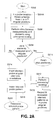
- FIG. 2B is a method flow chart for an array antenna illustrating an embodiment of the present invention for characterizing element patterns where the antenna element probe is moved and the antenna is fixed.
- FIG. 2C is a method flow chart for an array antenna illustrating an embodiment of the present invention for characterizing element patterns where both the antenna element probe and the antenna are moved relative to each other.
- FIG. 3 is a method flow chart for an array antenna illustrating an embodiment of the present invention for characterizing amplifier characteristics.
- FIG. 4 is a graphical plot for a phased array antenna comparing the antenna element-probe product patterns for edge elements obtained by using the prior art technique of single element measurement to patterns obtained by using the orthogonal coding technique, as illustrated in FIG. 2B, of the present invention.
- FIG. 5 is a graphical plot for a phased array antenna comparing the antenna element-probe product patterns for center elements obtained by using the prior art technique of single element measurement to patterns obtained by using the orthogonal coding technique, as illustrated in FIG. 2B, of the present invention.
- FIG. 6 is a graphical plot for a phased array antenna comparing the antenna element-probe product patterns for all 16 elements in a 2 ⁇ 8 array using the prior art technique to the antenna element-probe product patterns obtained using the orthogonal coding technique of the present invention as illustrated in FIG. 2 B.
- FIG. 7 is a graphical plot for a phased array antenna of the results obtained by the method for characterizing amplifier amplitude gain performance from CCE measurements, as illustrated in FIG. 3, of the present invention.
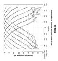
- FIG. 8 is a graphical plot for a phased array antenna of the results obtained the method for characterizing amplifier relative phase performance from CCE calibration measurements, as illustrated in FIG. 3, of the present invention.
- the system and method individually characterize any or all of the antenna elements in an array antenna system simultaneously, without the need to perform sequential measurements.
- the system and method individually characterize any or all of the amplifier characteristics, such as output signal amplitude and phase versus input signal amplitude of amplifiers corresponding to a plurality of array elements in an array antenna system simultaneously, without the need to perform sequential measurements.
- Functional schematic block diagrams of the apparatus hardware are shown in FIGS. 1A, 1 B, 1 C, 1 D, 1 E and 1 F and simplified flow charts of the method are shown in FIGS. 2A, 2 B, 2 C and FIG. 3 .
- FIG. 1A the apparatus hardware is described for an array antenna 100 in the transmit test mode.
- a calibration radio-frequency (RF) source 102 is coupled through optional switch 104 to the input of one of L beamformers 106 .
- Each beamformer 106 receives a beam through individual beam ports 108 from the calibration RF source 102 to each of N attenuators 110 and N phase shifters 112 , one set of one attenuator 110 and one phase shifter 112 for each of N antenna elements 114 .
- Each set of attenuator 110 and phase shifter 112 when desired is connected to one of N amplifiers 116 common to the nth corresponding set of attenuator 110 and phase shifter 112 on each of the L beamformers 106 .
- Each attenuator 110 is provided with its own signal control port 118 .
- each phase shifter 112 is provided with its own signal control port 120 .
- Each attenuator 110 is controlled typically digitally through its signal control port 118 to permit control of the attenuator function, although other suitable methods can be employed.
- each phase shifter 112 is controlled typically digitally through its signal control port 120 to permit control of the phase shifter function, although other suitable methods can be employed.
- a probe 122 is located, optionally using optional probe positioner 124 at a distance d away from the antenna array elements 114 , the distance d being nominally in the far-field of the antenna array elements 114 .
- the probe 122 is fixed in position and the entire antenna 100 is mounted on an antenna positioner 126 which permits rotation of the antenna 100 .
- the antenna 100 is rotated around a selected point. For an array antenna, this is typically around its phase center which is in the center of the aperture.
- the optional transmit/reception mode switch 104 is positioned such that the beam received by the probe 122 is transmitted to a coherent RF receiver 132 that ultimately transmits the signals through decoder/cross-correlator 134 to a processor 136 and on to a recorder 138 .
- transmit/receive mode switch 104 is preferably electronic in nature and that the electronic signals inherent in such devices can require many separate switchable paths to accomplish the desired switching function.
- switch 104 can be omitted and the network simply arranged in the desired manner for testing in the transmit mode by setting the calibration RF source 102 to couple directly to beam port 106 and by setting the probe 122 to couple directly to the coherent RF receiver 132 .
- the coherent RF receiver 132 is coherent with respect to the calibration RF source 102 .
- all of the N antenna elements 114 in a given one of the L beamformers 106 are encoded by applying a mutually orthogonal set of codes 140 thus allowing all antenna elements 114 to radiate simultaneously.
- a calibration signal from calibration RF source 102 and the orthogonal codes 140 as suggested by Silverstein et al., are applied to all of the control signal ports 118 and 120 of a single beamformer 106 .
- the orthogonal codes individually modulate the various phase shifters and amplitude controllers with separately identifiable codes, so that the signals applied to the various antenna elements 114 are encoded with the orthogonal codes.
- a mutually orthogonal code set is applied to the phase and amplitude controller corresponding to each of the elements 114 .
- the phase and/or amplitude of each element is toggled according to the sequence that constitutes the mutually orthogonal code set, thus providing a burst of RF modulated signal with the orthogonal code sequence encoding each element signal path.
- the decoder/cross-correlator 134 is used to decode the RF signal propagation characteristics corresponding to each of the element RF signal paths. Since there are N antenna elements 114 in each beamformer 106 and there are L beamformers 106 , there are approximately N ⁇ L bursts required. It is important to recognize that the element pattern is not a single plane pattern but generally is a two-dimensional pattern. Typically, the probe 122 takes azimuth and elevation scans.
- the amplitude and phase weights of the elemental signals which can be designated a 1 e j ⁇ 1 , a 2 e j ⁇ 2 , . . . , a n e j ⁇ N , respectively, are modulated by the various orthogonal codes.
- the various paths between the signal input ports 118 and 120 and each of the individual antenna elements 114 1 , 114 2 , . . . , 114 n , . . . , 114 N of array antenna 100 are modulated with different codes, so that a unique coding sequence is applied to each of the antenna element paths, by toggling at least one of amplitude and phase so as to provide a unique identifier for the signal path.
- the probe 122 receives the radiated signals from each elemental antenna 114 1 , 114 2 , . . . , 114 n , . . . , 114 N of the array antenna 100 with a phase and amplitude which depends upon the separation r, between the individual antenna elements and the probe, and the angular separation as it affects the radiation patterns of the elemental antennas and the probe.
- the signals received by the probe 122 are applied to coherent receiver 132 , and the resulting signal, which is a composite of all of the individual signals from the individual element antennas of the array 100 are applied to decoder/cross-correlator 134 .
- Decoder/cross-correlator 134 also receives the same set of orthogonal codes 140 and performs the decoding, so that the individual element signals can be extracted from the composite signal.
- the resulting unprocessed signals are designated E 1 , E 2 , . . . , E n , . . . , E N .
- Each of these signals represents one of the signals flowing in an independent path extending between one of the various individual antenna elements 114 1 , 114 2 , . . . , 114 n , . . . , 114 N of array antenna 100 and the probe 122 .
- each of the signals has its relative amplitude and phase a n e j ⁇ n encoded with the orthogonal coding sequence.
- the procedure for using a Hadamard matrix to generate the orthogonal encoding and decoding sequences is described in the above-mentioned Silverstein et al. patent. Other orthogonal encoding and decoding sequences known in the art can be applied as well.
- the processor 136 uses knowledge of relative probe-element positions and orientations 142 and the inherent known probe patterns 144 to compute the antenna element patterns 146 in the array environment, record the patterns 146 in the recorder 138 and optionally display and/or print out the antenna element patterns 146 in optional printer and/or display unit 152 , for each of the positions for which the RF fields are sampled.
- the processor 136 uses knowledge of relative probe-element positions and orientations 142 and the input signal levels 148 to compute the amplifier characteristics 150 in the array environment, records the amplifier characteristics 150 in the recorder 138 and optionally displays and/or prints out the amplifier characteristics 150 in the optional printer and/or display unit 152 , for each of the signal levels for which the RF fields are sampled with both the probe 122 and the antenna 100 being maintained at the same fixed position with respect to each other for all readings.
- Antenna controller 154 operates software which controls relative positions between the antenna and the probe, and which also controls the signal coding process.
- antenna controller 154 comprises typically a multiplexer-type process control unit which is typically hard-wired throughout to the system apparatus hardware illustrated in FIG. 1 A.
- antenna positioner 126 can be held in a fixed position for all readings, so that both the probe 122 and the antenna 100 are maintained at the same fixed position with respect to each other for all readings.
- FIG. 1C illustrates the identical embodiment of the present invention in the transmit test mode as is illustrated in FIG. 1A except that instead of the probe 122 being fixed in position and the antenna 100 being rotated by antenna positioner 126 , the probe 122 is mounted on a movement track 128 and the probe 122 is moved along the movement track 128 by probe positioner 124 to again position the probe 122 at any one of M positions 130 corresponding to the boresight position, or in the vicinity of the boresight position, of any one of N antenna elements 114 .
- FIG. 1E illustrates the identical embodiment of the present invention in the transmit test mode as is illustrated in FIG. 1A or FIG. 1C except that instead of the probe 122 being fixed in position and the antenna 100 being rotated by antenna positioner 126 , or the probe 122 mounted on a movement track 128 and the probe 122 moved along the movement track 128 by probe positioner 124 and the antenna 100 fixed in position, both the probe 122 and the antenna 100 are capable of being moved.
- the probe 122 is mounted on a movement track 128 and the probe 122 is moved along the movement track 128 by probe positioner 124 .
- movement track 128 is not limited to a linear track but can be of any shape to permit variable positioning of the probe 122 , such as would be achieved with a “roller coaster” design or a spherical surface design.
- the apparatus hardware is described for an array antenna 100 in the receive test mode.
- the optional transmit/receive mode switch 104 preferably electronic as described above, is positioned such that the calibration RF source 102 supplies an RF signal to the probe 122 .
- switch 104 can be omitted and the network simply arranged in the desired manner for testing in the reception mode by setting the calibration RF source 102 to couple directly to the probe 122 and by setting the beam port 106 to couple directly to coherent RF receiver 132 .
- FIG. 1B as is the case for the transmit mode illustrated in FIG.
- the probe 122 is fixed in position and the entire antenna 100 is mounted on an antenna positioner 126 which permits rotation of the antenna 100 .
- the antenna 100 is rotated around a selected point. For an array antenna, this is typically around its phase center which is in the center of the aperture.
- Calibration RF source 102 transmits a calibration signal to probe 122 .
- the probe 122 transmits the signal received from the coherent RF source 102 to the N antenna elements 114 and the signals are transmitted through amplifiers 116 , now oriented in the reverse direction as compared to the transmit test mode, and through phase shifters 112 and 110 , each of which are mounted on beamformer 106 . Therefore, the signal produced at the receive antenna beam port 106 is the calibration signal from calibration RF source 102 encoded or modulated with the orthogonal codes 140 .
- the signals pass through beam port 106 and are coupled to the coherent RF receiver 132 and through the remainder of the circuit exactly as before for the transmit case described in FIG. 1A to obtain the resulting element patterns 146 or amplifier characteristics 150 .
- all of the N antenna elements 114 are encoded by applying a mutually orthogonal set of codes 140 thus allowing all antenna elements 114 to receive simultaneously.
- the orthogonal codes 140 as suggested by Silverstein et al. are applied to control signal input ports 118 and 120 of all L beamformers 106 .
- the orthogonal codes individually modulate the various phase shifters and amplitude controllers with separately identifiable codes, so that the signals applied to the various antenna elements 114 are encoded with the orthogonal codes.
- the orthogonal codes individually modulate the various phase shifters and amplitude controllers with separately identifiable codes, so that the signals applied to the various antenna elements 114 are encoded with the orthogonal codes.
- a mutually orthogonal code set is applied to the phase and amplitude controller corresponding to each of the elements 114 .
- the phase and/or amplitude of each element is toggled according to the sequence that constitutes the mutually orthogonal code set, thus providing a burst of RF modulated signal with the orthogonal code sequence encoding each element signal path.
- the decoder/cross-correlator 134 is used to decode the RF signal propagation characteristics corresponding to each of the element RF signal paths. Since there are N antenna elements 114 in each beamformer 106 and there are L beamformers 106 , there are approximately N ⁇ L bursts required. It is important to recognize that the element pattern is not a single plane pattern but generally is a two-dimensional pattern. Typically, the probe 122 takes azimuth and elevation scans.
- the processor 136 uses knowledge of relative probe-element positions and orientations 142 and the known probe patterns 144 to compute the antenna element patterns 146 in the array environment, record the patterns 146 in the recorder 138 and optionally display and/or print out the antenna element patterns 146 in optional printer and/or display unit 152 , for each of the positions 122 for which the RF fields are sampled
- the processor 136 uses knowledge of relative probe-element positions and orientations 142 and the input signal levels 148 to compute the amplifier characteristics 150 in the array environment, record the amplifier characteristics 150 in recorder 138 and optionally display and/or print out the amplifier characteristics 150 in the printer and/or display unit 152 , for each of the signal levels 148 for which the RF fields are sampled with both the probe 122 and the antenna 100 being maintained at the same fixed position with respect to each other for all readings.
- Antenna controller 154 operates software which controls relative positions between the antenna and the probe, and which also controls the signal coding process.
- antenna controller 154 comprises typically a multiplexer-type process control unit which is typically hard-wired throughout to the system apparatus hardware illustrated in FIG. 1 B.
- antenna positioner 126 can be held in a fixed position for all readings, so that both the probe 122 and the antenna 100 are maintained at the same fixed position with respect to each other for all readings.
- FIG. 1D illustrates the identical embodiment of the present invention in the receive test mode as is illustrated in FIG. 1B except that instead of the probe 122 being fixed in position and the antenna 100 being rotated by antenna positioner 126 , the probe 122 is mounted on a movement track 128 and the probe 122 is moved along the movement track 128 by probe positioner 124 to again position the probe 122 at any one of M positions 130 corresponding to the boresight position, or in the vicinity of the boresight position, of any one of N antenna elements 114 .
- FIG. 1F illustrates the identical embodiment of the present invention in the receive test mode as is illustrated in FIG. 1B or FIG. 1D except that instead of the probe 122 being fixed in position and the antenna 100 being rotated by antenna positioner 126 , or the probe 122 mounted on a movement track 128 and the probe 122 moved along the movement track 128 by probe positioner 124 and the antenna 100 fixed in position, both the probe 122 and the antenna 100 are capable of being moved.
- the probe 122 is mounted on a movement track 128 and the probe 122 is moved along the movement track 128 by probe positioner 124 .
- movement track 128 is not limited to a linear track but can be of any shape to permit variable positioning of the probe 122 , such as would be achieved with a “roller coaster” design or a spherical surface design.
- FIG. 2A is a flow chart which illustrates the method steps to obtain the resulting antenna element patterns 146 of the antenna elements 114 , at a desired frequency and ambient temperature, when the probe 122 is fixed in position and the array antenna 100 is rotated by antenna positioner 126 . Since the probe 122 has its own inherent amplitude and phase characteristic patterns, prior to starting the antenna element pattern characterization process, the probe's inherent amplitude and phase characteristic patterns are determined, resulting in a known probe pattern 144 . Once the probe's inherent pattern has become known, the element pattern characterization is started, and at each probe-element position and orientation 142 , an orthogonal encoding and decoding measurement set is performed. The desired element patterns 146 are reconstructed by performing multiple samples of the element patterns, and scaling the results by the appropriate probe-element distance and the known probe pattern 144 .
- step S 200 allows for determining the probe's inherent amplitude and phase characteristic patterns. Then, start of operations begins in step S 202 , with the probe 122 in a fixed position opposite to, or in the vicinity of, and in front of one of N antenna elements 114
- Step S 204 A allows for rotating the array antenna 100 around its phase center in the center of the aperture.
- Step S 206 allows for performing simultaneous measurements of all N antenna elements 114 using the orthogonal coding 140 as described above, (a) when the array antenna 100 is a transmit antenna, the calibration signal emitted from the calibration RF source 102 is transmitted to the antenna beam ports 108 and (b) when the array antenna 100 is a receive antenna, the calibration signal emitted from the calibration RF source 102 is transmitted to the probe 122 .
- step S 208 allows for proceeding to step S 210 if all M element-probe angular positions have been measured. If not, the process returns to step S 204 A until all of the desired M element-probe angular positions have been measured.
- step S 210 Upon completion of the mth probe position, step S 210 allows for finishing the measurements and stopping the antenna positioner 126 .
- Step S 212 allows for performing the processing (determining the scaling factors) for the antenna element positions by step S 214 which allows for inserting the element-probe positions and orientations 142 and by step S 216 which allows for inserting the inherent probe pattern 144 determined in step S 200 .
- step 218 allows for recording all of the N recovered antenna element patterns 146 versus the M antenna element positions and orientations 142 .
- FIG. 2B is a flow chart which illustrates the method steps to obtain the resulting antenna element patterns 146 of the antenna elements 114 , again at a desired frequency and ambient temperature, as the probe 122 is moved along the positioner track 128 and the array antenna 100 is maintained in a fixed position.
- the probe 122 since the probe 122 has its own inherent amplitude and phase characteristic patterns, prior to starting the antenna element pattern characterization process, the probe's inherent amplitude and phase characteristic patterns are determined, resulting in a known probe pattern 144 .
- the element pattern characterization is started, and at each probe position 130 , an orthogonal encoding and decoding measurement set is performed.
- the desired element patterns 146 are reconstructed by performing multiple samples of the element patterns, and scaling the results by the appropriate probe-element positions and orientations 142 and the known probe pattern 144 .
- FIG. 2B illustrates the identical method steps as FIG. 2A, except that after Step 200 where the probe's inherent characteristics are determined and the start of operations begins in step S 202 , step S 204 B allows for moving the probe positioner 124 along the movement track 128 such that the probe 122 is positioned at the first of M positions opposite to, or in the vicinity of, and in front of one of N antenna elements 114 . All remaining steps, beginning with step S 206 are identical.
- step S 206 allows for performing simultaneous measurements of all N antenna elements 114 using the orthogonal coding 140 as described above, (a) when the antenna 100 is a transmit antenna, the calibration signal emitted from the calibration RF source 102 is transmitted to the antenna beam ports 108 and (b) when the antenna 100 is a receive antenna, the calibration signal emitted from the calibration RF source 102 is transmitted to the probe 122 .
- decision step S 208 allows for proceeding to step S 210 if all M probe positions 130 have been measured. If not, the process returns to step S 204 until the probe 122 has been positioned at all of the desired M probe positions. 130 .
- step S 210 Upon completion of the mth probe position, step S 210 allows for finishing the measurements and stopping the probe positioner 120 .
- Step S 212 allows for performing the processing (determining the scaling factors) for the probe positions by step S 214 which allows for inserting the element-probe positions and orientations 142 and by step S 216 which allows for inserting the probe's inherent pattern 144 determined in step S 200 .
- step S 218 allows for recording all of the N recovered antenna element patterns 146 versus the M antenna element angular positions.
- FIG. 2C is a flow chart which illustrates the method steps to obtain the resulting antenna element patterns 146 of the antenna elements 114 , also at a desired frequency and ambient temperature, as the probe 122 is moved along the positioner track 128 and the array antenna 100 is not maintained in a fixed position but is instead rotated by antenna positioner 126 .
- the method steps are identical to those described in FIG. 2 A and FIG.
- step S 204 C allows for moving the probe positioner 124 along the movement track 128 and rotating the array antenna 100 by the antenna positioner 126 such that the probe 122 is positioned at the first of M positions corresponding to the boresight position, or in the vicinity of, the boresight position and in front of one of N antenna elements 114 .
- the processing of the signals received by the probe when in the transmit mode and received by the antenna elements when in the receive mode is performed by cross-correlating the received signals with the orthogonal codes, to produce the unprocessed signals, E 1 , E 2 , . . . , E n , . . . , E N .
- E nm a n ⁇ ⁇ jk ⁇ ⁇ ⁇ ⁇ ⁇ n ⁇ g n ⁇ ( ⁇ nm e ) ⁇ f ⁇ ( ⁇ nm p ) ⁇ ⁇ exp ⁇ ( jkr nm ) r nm
- r nm is the distance between the n-th element and the m-th probe sample point
- k is the wave number (2 ⁇ /wavelength)
- g n ( ⁇ e nm ) is the n-th element pattern to be determined
- f( ⁇ p nm ) is the probe pattern measured or predicted by calculation prior starting the process
- ⁇ e nm defines the angles between the n-th antenna element boresight and the m-th probe direction
- ⁇ p nm defines the angles between the m-th antenna probe boresight position and the n-th antenna element.
- S nm r nm ⁇ exp ⁇ ( - jkr nm ) g n ⁇ ( ⁇ nm e ) ⁇ f ⁇ ( ⁇ nm p )
- the recovered amplitude and phase weights for each of the elements of the antenna array are then used in the conventional manner to calibrate the array, and to provide correction of the far-field pattern.
- FIG. 3 is a flow chart which illustrates the method steps to obtain the amplifier characteristics 150 of the antenna elements 114 , at a desired frequency and ambient temperature, as the probe 122 is set at a fixed position relative to, and in front of, the array antenna 100 and nominally coincident with the boresight direction of the array antenna 100 .
- it is desired to obtain the amplifier characteristics for an active transmit array antenna In such a case, any of the arrangements of the systems illustrated in FIG. 1A, FIG. 1C, and FIG. 1E for the transmit mode can be used as long as during the measurements the probe 122 is set at a fixed position relative to the array antenna 100 and nominally coincident with the boresight direction of the array antenna 100 .
- an orthogonal encoding and decoding measurement set is performed at the fixed probe position.
- the desired amplifier characteristics are reconstructed by performing multiple samples of the signal levels; and scaling the results by the appropriate probe-element distance and known probe pattern determined before the start of the calibration procedure.
- Step S 300 allows for setting the probe 122 at a fixed position relative to array antenna 100 nominally coincident with the boresight direction of the array antenna 100 .
- step S 304 allows for setting the input signal strength to the kth level.
- step S 306 allows for performing simultaneous measurements of all N antenna elements 114 using the orthogonal coding 140 as described above.
- decision step S 308 allows for proceeding to step S 310 if all N antenna elements 114 have been measured to the k th level. If not, the process returns to step S 304 until all N antenna elements 114 have been measured to the k th level.
- step S 310 Upon completion of the k th signal level, step S 310 allows for finishing the measurements and stopping the changing of the signal levels.
- Step S 312 allows for performing the processing by determining the scaling factors for the distances of the antenna elements 114 from the fixed probe position by step S 314 which allows for inserting the recorded input signal levels 148 .
- step S 316 allows for recording all of the N recovered amplifier characteristics in the form of output signal levels 150 versus the K input signal levels 148 .
- this process is very useful for obtaining antenna element patterns for use in conjunction with the above-mentioned near-field calibration system described by Lier et al.
- the arrangement for near-field calibration of the phase of the phase shifters, amplitude attenuators, or both, which are associated with each of the elements of the array 100 provides an improvement over the above-mentioned technique by Silverstein et al., because the Silverstein technique is a far-field measurement, and as such requires a remote site, and the need for coherent or synchronous reception, in conjunction with the remote site, in turn requires a communication path for synchronization, which introduces system complications.
- the scaling factors and recovered amplitude and phase weights for each of the elements of the antenna array are used in the conventional manner to calibrate the array, and to provide for correction of the far-field pattern.
- the method would be useful for any other array antenna projects where one is interested in determining the antenna element patterns in the array environment.
- the determination of the radiation patterns of the various elemental antennas of the array may require actual measurements of antenna elements located at representative positions in the array, as for example at the center and at the edges. Similarly, actual measurements may be required to determine the radiation pattern of the probe antenna.
- the output of the decoder provides a set of complex weights, E nm , calculated as defined above.
- the scaling factor, S nm contains the probe-element factor which, using the above procedure, is obtained from the measured data.
- the technique was demonstrated using a 2 ⁇ 8 C-band test array in the transmit mode and a near-field positioner system to move the probe along various points along a linear track.
- the linear track was chosen due to availability and simplicity in determining the element-probe distances. Fifteen (15) elements were terminated and one element excited so that a set of single element measurements could be obtained.
- the probe-element products were measured in a conventional way for a center element and an edge element. A distance of 4 feet (1.2 meters) between the probe track and the array was selected and the probe placed just in the far-field of the 7 inch (17.8 cm) horn apertures. Measurements were performed at a frequency of 4.0 GHz.
- the probe used was an open ended C-band (WR-229) waveguide.
- FIG. 4 the measured results are illustrated for center elements obtained using both the single antenna element technique of the prior art and the orthogonal coding technique of the present invention as illustrated by FIG. 2 B.
- FIG. 5 the measured results are illustrated for edge elements obtained using both the single antenna element technique of the prior art and the orthogonal coding technique of the present invention as illustrated by FIG. 2 B.
- FIG. 6 illustrates the results obtained for all 16 antenna elements, included on the same graph, again using the single antenna element technique of the prior art and the orthogonal coding technique of the present invention as illustrated in FIG. 2B; see D. S.
- FIGS. 4, 5 and 6 illustrate the speed and efficiency by which the antenna element patterns can be obtained, since all 16 antenna elements were characterized simultaneously in only a few minutes, during just one probe-track movement set. Since all antenna elements were measured simultaneously, it was not necessary to disconnect and terminate the 15 antenna elements while exciting just one antenna element as is done using the prior art methods.
- FIG. 7 a graphical plot for an array antenna of the results obtained by the method of FIG. 3 for characterizing amplifier amplitude gain performance from CCE calibration measurements of the present invention is illustrated.
- the plots of FIG. 7 show the AM-to-AM curves or, equivalently, the output signal behavior versus input signal strength for 14 different elements in the array.
- the curves show a non-linear behavior of the amplifiers. Such non-linear characteristics can be analyzed by various models such as the Shimbo model referenced previously.
- FIG. 8 a graphical plot for a phased array antenna of the results obtained by the method of FIG. 3 for characterizing amplifier relative phase performance from CCE calibration measurements of the present invention is illustrated.
- the plots of FIG. 8 show the AM-to-PM curves or, equivalently, the output phase versus input signal strength for 14 different elements in the array.
- Such phase characteristics can be used in various models, again such as the Shimbo model referenced previously.
- this process is very useful for obtaining antenna element patterns for use in conjunction with the above-mentioned near-field calibration system described by Lier et al.
- the arrangement for near-field calibration of the phase of the phase shifters, amplitude attenuators, or both, which are associated with each of the elements of the array 100 provides an improvement over the above-mentioned technique by Silverstein et al., because the Silverstein technique is a far-field measurement, and as such requires a remote site, and the need for coherent or synchronous reception, in conjunction with the remote site, in turn requires a communication path for synchronization, which introduces system complications.
- the scaling factors and recovered amplitude and phase weights for each of the elements of the antenna array are used in the conventional manner to calibrate the array, and to provide for correction of the far-field pattern.
- the method would be useful for any other array antenna projects where one is interested in determining the antenna element patterns in the array environment.
- the determination of the radiation patterns of the various elemental antennas of the array may require actual measurements of antenna elements located at representative positions in the array, as for example at the center and at the edges. Similarly, actual measurements may be required to determine the radiation pattern of the probe antenna.
- FIG. 1 A and FIG. 1B illustrate calibration on only one of the transmit and receive antennas at a time because a single transmit antenna and a single receive antenna are illustrated in each figure. If there are plural transmit and receive antennas, some transmit antennas can be calibrated at the same time that receive antennas are being calibrated.
- the experimental data obtained using this current method of determining antenna element patterns is shown to compare well to the data collected using a single antenna element measurement technique.
- This current invention is especially useful for factory testing and diagnostic assessment of phased-arrays with a large number of antenna elements.
- This current method is easily automated and eliminates the need for manually removing cables and installing terminations.
- the method for characterizing amplifier properties “piggy-backs” on essentially the same hardware and similar software as the method for determining antenna element patterns and offers essentially the same advantages of speed and reduced parts integration and test time.
- Amplifier characterization is typically of interest for an “active” transmit array where “active” refers to the case where the amplifiers are distributed amplifiers located near the antenna elements.
Landscapes
- Variable-Direction Aerials And Aerial Arrays (AREA)
Abstract
Description


Claims (36)
Priority Applications (1)
| Application Number | Priority Date | Filing Date | Title |
|---|---|---|---|
| US09/848,063 US6507315B2 (en) | 2001-05-03 | 2001-05-03 | System and method for efficiently characterizing the elements in an array antenna |
Applications Claiming Priority (1)
| Application Number | Priority Date | Filing Date | Title |
|---|---|---|---|
| US09/848,063 US6507315B2 (en) | 2001-05-03 | 2001-05-03 | System and method for efficiently characterizing the elements in an array antenna |
Publications (2)
| Publication Number | Publication Date |
|---|---|
| US20020171583A1 US20020171583A1 (en) | 2002-11-21 |
| US6507315B2 true US6507315B2 (en) | 2003-01-14 |
Family
ID=25302231
Family Applications (1)
| Application Number | Title | Priority Date | Filing Date |
|---|---|---|---|
| US09/848,063 Expired - Lifetime US6507315B2 (en) | 2001-05-03 | 2001-05-03 | System and method for efficiently characterizing the elements in an array antenna |
Country Status (1)
| Country | Link |
|---|---|
| US (1) | US6507315B2 (en) |
Cited By (30)
| Publication number | Priority date | Publication date | Assignee | Title |
|---|---|---|---|---|
| US20030038747A1 (en) * | 2001-08-23 | 2003-02-27 | Jaynesh Patel | Nearfield calibration method used for phased array antennas containing tunable phase shifters |
| US20030090418A1 (en) * | 2001-11-09 | 2003-05-15 | Howell James M. | Beamformer for multi-beam broadcast antenna |
| US6636173B2 (en) * | 2001-12-20 | 2003-10-21 | Lockheed Martin Corporation | Calibration system and method for phased array antenna using near-field probe and focused null |
| US20030204640A1 (en) * | 2002-04-30 | 2003-10-30 | Nokia Corporation | Method and device for management of tree data exchange |
| US6686873B2 (en) * | 2001-08-23 | 2004-02-03 | Paratek Microwave, Inc. | Farfield calibration method used for phased array antennas containing tunable phase shifters |
| US6738017B2 (en) | 2002-08-06 | 2004-05-18 | Lockheed Martin Corporation | Modular phased array with improved beam-to-beam isolation |
| US20040196203A1 (en) * | 2002-09-11 | 2004-10-07 | Lockheed Martin Corporation | Partly interleaved phased arrays with different antenna elements in central and outer region |
| US7050019B1 (en) | 2002-09-11 | 2006-05-23 | Lockheed Martin Corporation | Concentric phased arrays symmetrically oriented on the spacecraft bus for yaw-independent navigation |
| US20080129613A1 (en) * | 2006-12-05 | 2008-06-05 | Nokia Corporation | Calibration for re-configurable active antennas |
| US20080153433A1 (en) * | 2006-12-21 | 2008-06-26 | Nokia Corporation | Phase and power calibration in active antennas |
| US20120146840A1 (en) * | 2010-12-09 | 2012-06-14 | Denso Corporation | Phased array antenna and its phase calibration method |
| US20120146841A1 (en) * | 2010-12-09 | 2012-06-14 | Denso Corporation | Phased array antenna and its phase calibration method |
| US20130234883A1 (en) * | 2012-02-24 | 2013-09-12 | Futurewei Technologies, Inc. | Apparatus and Method for an Active Antenna System with Near-field Radio Frequency Probes |
| US8907842B1 (en) | 2009-03-25 | 2014-12-09 | Raytheon Company | Method and apparatus for attenuating a transmitted feedthrough signal |
| US9019153B1 (en) * | 2011-12-20 | 2015-04-28 | Raytheon Company | Calibration of large phased arrays using fourier gauge |
| US9070964B1 (en) | 2011-12-19 | 2015-06-30 | Raytheon Company | Methods and apparatus for volumetric coverage with image beam super-elements |
| US9086476B1 (en) | 2009-03-25 | 2015-07-21 | Raytheon Company | Method and apparatus for rejecting intermodulation products |
| US20150349420A1 (en) * | 2014-02-13 | 2015-12-03 | The United States Of America As Represented By The Secretary Of The Navy | Planar near-field calibration of digital arrays using element plane wave spectra |
| US20150349419A1 (en) * | 2014-02-13 | 2015-12-03 | The United States Of America As Represented By The Secretary Of The Navy | Planar near-field calibration of digital arrays using element plane wave spectra |
| US9209523B2 (en) | 2012-02-24 | 2015-12-08 | Futurewei Technologies, Inc. | Apparatus and method for modular multi-sector active antenna system |
| US9373888B1 (en) | 2009-03-25 | 2016-06-21 | Raytheon Company | Method and apparatus for reducing sidelobes in large phased array radar with super-elements |
| US9379446B1 (en) | 2013-05-01 | 2016-06-28 | Raytheon Company | Methods and apparatus for dual polarized super-element phased array radiator |
| US9791552B1 (en) * | 2014-11-19 | 2017-10-17 | Src, Inc. | On-site calibration of array antenna systems |
| US10281571B2 (en) | 2014-08-21 | 2019-05-07 | Raytheon Company | Phased array antenna using stacked beams in elevation and azimuth |
| CN109813968A (en) * | 2017-11-21 | 2019-05-28 | 深圳市通用测试系统有限公司 | A kind of measurement method of array aerial direction figure, equipment, system and computer readable storage medium |
| CN111987462A (en) * | 2020-08-21 | 2020-11-24 | 北京航空航天大学 | Phased array antenna phase calibration measurement system and method |
| US11404778B2 (en) * | 2019-04-29 | 2022-08-02 | Steppir Communication Systems, Inc. | Phased-array antenna system having variable phasing and resonance control |
| US20220268886A1 (en) * | 2019-07-16 | 2022-08-25 | Metawave Corporation | Phased array antenna calibration system and methods for use in millimeter wave applications |
| US11721894B2 (en) * | 2020-04-03 | 2023-08-08 | The Boeing Company | System and method for near-field testing of a phased array antenna |
| US20260051932A1 (en) * | 2023-04-26 | 2026-02-19 | CesiumAstro, Inc. | Hybrid Digital Delay Beamforming Circuits and Methods |
Families Citing this family (36)
| Publication number | Priority date | Publication date | Assignee | Title |
|---|---|---|---|---|
| JP3601598B2 (en) * | 2001-05-11 | 2004-12-15 | 日本電気株式会社 | Adaptive antenna receiver |
| US6703976B2 (en) * | 2001-11-21 | 2004-03-09 | Lockheed Martin Corporation | Scaleable antenna array architecture using standard radiating subarrays and amplifying/beamforming assemblies |
| US7684776B2 (en) * | 2002-12-24 | 2010-03-23 | Intel Corporation | Wireless communication device having variable gain device and method therefor |
| US7456787B2 (en) * | 2005-08-11 | 2008-11-25 | Sierra Nevada Corporation | Beam-forming antenna with amplitude-controlled antenna elements |
| US8456360B2 (en) * | 2005-08-11 | 2013-06-04 | Sierra Nevada Corporation | Beam-forming antenna with amplitude-controlled antenna elements |
| US7317428B2 (en) * | 2006-01-10 | 2008-01-08 | Lucent Technologies Inc. | Forming an antenna beam using an array of antennas to provide a wireless communication |
| US7345629B2 (en) * | 2006-02-21 | 2008-03-18 | Northrop Grumman Corporation | Wideband active phased array antenna system |
| US7876276B1 (en) | 2006-08-02 | 2011-01-25 | The United States Of America As Represented By The Administrator Of The National Aeronautics And Space Administration | Antenna near-field probe station scanner |
| US8212716B2 (en) * | 2007-12-31 | 2012-07-03 | Elta Systems Ltd. | System and method for calibration of phased array antenna having integral calibration network in presence of an interfering body |
| IL188507A (en) * | 2007-12-31 | 2012-06-28 | Elta Systems Ltd | Phased array antenna having integral calibration network and method for measuring calibration ratio thereof |
| IL199560A (en) * | 2009-06-25 | 2017-04-30 | Elta Systems Ltd | System and method for calibration of phased array antenna having integral calibration network in presence of an interfering body |
| US8494445B2 (en) * | 2010-02-03 | 2013-07-23 | Viasat, Inc. | Flexible coverage areas for forward link signals in a spot beam satellite communication system |
| CN102834724A (en) * | 2010-04-22 | 2012-12-19 | 诺基亚西门子通信公司 | Apparatus for measuring a radiation pattern of an active antenna arrangement |
| CN103024807B (en) | 2011-09-23 | 2015-08-19 | 华为技术有限公司 | The method of control information transmission, subscriber equipment and base station |
| US9450659B2 (en) * | 2011-11-04 | 2016-09-20 | Alcatel Lucent | Method and apparatus to generate virtual sector wide static beams using phase shift transmit diversity |
| US9300408B2 (en) * | 2013-11-04 | 2016-03-29 | Alcatel-Lucent Shanghai Bell Co., Ltd | Methods and systems for calibrating LTE antenna systems |
| US9893715B2 (en) * | 2013-12-09 | 2018-02-13 | Shure Acquisition Holdings, Inc. | Adaptive self-tunable antenna system and method |
| RU2594385C1 (en) * | 2015-05-25 | 2016-08-20 | Открытое акционерное общество "Российская корпорация ракетно-космического приборостроения и информационных систем" (ОАО "Российские космические системы") | Method of processing broadband signals and device of phasing antennae receiving broadband signals, mainly for no-equidistant antenna array |
| US10211904B2 (en) * | 2016-04-19 | 2019-02-19 | Telefonaktiebolaget Lm Ericsson (Publ) | Power control and beamforming with a plurality of power amplifiers |
| US9642107B1 (en) | 2016-08-01 | 2017-05-02 | Space Systems/Loral, Inc. | Multi-channel satellite calibration |
| US20180062260A1 (en) | 2016-08-26 | 2018-03-01 | Analog Devices Global | Antenna array calibration systems and methods |
| EP3293897B8 (en) * | 2016-09-12 | 2020-08-12 | Rohde & Schwarz GmbH & Co. KG | System and method for characterization of multi-element antenna |
| CN109815509B (en) * | 2017-11-21 | 2023-08-08 | 深圳市通用测试系统有限公司 | A diagnostic method, device, system, and computer-readable storage medium for an array antenna |
| CN109813967B (en) * | 2017-11-21 | 2022-05-17 | 深圳市通用测试系统有限公司 | Method, device and system for measuring array antenna pattern |
| WO2019154517A1 (en) * | 2018-02-12 | 2019-08-15 | Nokia Technologies Oy | Coordinated precoding and beamforming of position purpose signals |
| US11177567B2 (en) * | 2018-02-23 | 2021-11-16 | Analog Devices Global Unlimited Company | Antenna array calibration systems and methods |
| CN108562801B (en) * | 2018-05-07 | 2023-05-12 | 北京中微普业科技有限公司 | Array antenna test system and test method thereof |
| US11349208B2 (en) | 2019-01-14 | 2022-05-31 | Analog Devices International Unlimited Company | Antenna apparatus with switches for antenna array calibration |
| US11404779B2 (en) | 2019-03-14 | 2022-08-02 | Analog Devices International Unlimited Company | On-chip phased array calibration systems and methods |
| JPWO2020213093A1 (en) * | 2019-04-17 | 2020-10-22 | ||
| WO2021152348A1 (en) * | 2020-01-30 | 2021-08-05 | Telefonaktiebolaget Lm Ericsson (Publ) | Antenna calibration using fountain coded sequence |
| US11450952B2 (en) | 2020-02-26 | 2022-09-20 | Analog Devices International Unlimited Company | Beamformer automatic calibration systems and methods |
| US11729789B2 (en) * | 2020-08-25 | 2023-08-15 | Qualcomm Incorporated | Beam correlation across frequency bands |
| EP4292215A4 (en) * | 2021-02-11 | 2025-01-15 | Saab Ab | METHOD AND DEVICE FOR CONTROLLING THE OUTPUT POWER OF MULTIPLE AMPLIFIERS |
| EP4451572A3 (en) * | 2021-05-17 | 2024-12-25 | Beammwave AB | Digital pre-processing chip for mmwave transceiver architectures |
| FR3129787B1 (en) * | 2021-12-01 | 2025-02-21 | Commissariat Energie Atomique | Controlled Radiation Antenna System |
Citations (2)
| Publication number | Priority date | Publication date | Assignee | Title |
|---|---|---|---|---|
| US6084545A (en) | 1999-07-12 | 2000-07-04 | Lockheed Martin Corporation | Near-field calibration system for phase-array antennas |
| US6163296A (en) | 1999-07-12 | 2000-12-19 | Lockheed Martin Corp. | Calibration and integrated beam control/conditioning system for phased-array antennas |
-
2001
- 2001-05-03 US US09/848,063 patent/US6507315B2/en not_active Expired - Lifetime
Patent Citations (2)
| Publication number | Priority date | Publication date | Assignee | Title |
|---|---|---|---|---|
| US6084545A (en) | 1999-07-12 | 2000-07-04 | Lockheed Martin Corporation | Near-field calibration system for phase-array antennas |
| US6163296A (en) | 1999-07-12 | 2000-12-19 | Lockheed Martin Corp. | Calibration and integrated beam control/conditioning system for phased-array antennas |
Non-Patent Citations (5)
| Title |
|---|
| Mailloux, Robert J. "Phased Array Antenna Handbook" Artech House, Boston, 1993, pp. 63-68. |
| Purdy, Daniel S. "An Automated Process for Efficiently Measuring the Patterns of All Elements Located in a Phased-Array Antenna" 2000 IEEE International Conference on Phased Array Systems and Technology, May 2000, pp. 521-524. |
| Purdy, Daniel S. and Anthony Jacomb-Hood, "In Orbit Active Array Calibration for NASA's LightSAR" IEEE, 1999, pp. 172-176. |
| Silverstein, Seth D. "Application of Orthogonal Codes to the Calibration of Active Phased Array Antennas for Communication Satellites" IEEE, 1997, pp. 206-218. |
| Skolnik, Merrill I. "Radar Handbook" McGraw-Hill Publishing, New York, 1990, pp. 7.1, 7.35-7.36. |
Cited By (46)
| Publication number | Priority date | Publication date | Assignee | Title |
|---|---|---|---|---|
| US20030038747A1 (en) * | 2001-08-23 | 2003-02-27 | Jaynesh Patel | Nearfield calibration method used for phased array antennas containing tunable phase shifters |
| US6686873B2 (en) * | 2001-08-23 | 2004-02-03 | Paratek Microwave, Inc. | Farfield calibration method used for phased array antennas containing tunable phase shifters |
| US6771216B2 (en) * | 2001-08-23 | 2004-08-03 | Paratex Microwave Inc. | Nearfield calibration method used for phased array antennas containing tunable phase shifters |
| US20030090418A1 (en) * | 2001-11-09 | 2003-05-15 | Howell James M. | Beamformer for multi-beam broadcast antenna |
| US6788250B2 (en) * | 2001-11-09 | 2004-09-07 | Ems Technologies, Inc. | Beamformer for multi-beam broadcast antenna |
| US7109919B2 (en) | 2001-11-09 | 2006-09-19 | Ems Technologies, Inc. | Beamformer for multi-beam broadcast antenna |
| US20050128141A1 (en) * | 2001-11-09 | 2005-06-16 | Howell James M. | Beamformer for multi-beam broadcast antenna |
| US6636173B2 (en) * | 2001-12-20 | 2003-10-21 | Lockheed Martin Corporation | Calibration system and method for phased array antenna using near-field probe and focused null |
| US20030204640A1 (en) * | 2002-04-30 | 2003-10-30 | Nokia Corporation | Method and device for management of tree data exchange |
| US6738017B2 (en) | 2002-08-06 | 2004-05-18 | Lockheed Martin Corporation | Modular phased array with improved beam-to-beam isolation |
| US7050019B1 (en) | 2002-09-11 | 2006-05-23 | Lockheed Martin Corporation | Concentric phased arrays symmetrically oriented on the spacecraft bus for yaw-independent navigation |
| US20040196203A1 (en) * | 2002-09-11 | 2004-10-07 | Lockheed Martin Corporation | Partly interleaved phased arrays with different antenna elements in central and outer region |
| US20080129613A1 (en) * | 2006-12-05 | 2008-06-05 | Nokia Corporation | Calibration for re-configurable active antennas |
| US20080153433A1 (en) * | 2006-12-21 | 2008-06-26 | Nokia Corporation | Phase and power calibration in active antennas |
| US7764935B2 (en) | 2006-12-21 | 2010-07-27 | Nokia Corporation | Phase and power calibration in active antennas |
| US9373888B1 (en) | 2009-03-25 | 2016-06-21 | Raytheon Company | Method and apparatus for reducing sidelobes in large phased array radar with super-elements |
| US8907842B1 (en) | 2009-03-25 | 2014-12-09 | Raytheon Company | Method and apparatus for attenuating a transmitted feedthrough signal |
| US9086476B1 (en) | 2009-03-25 | 2015-07-21 | Raytheon Company | Method and apparatus for rejecting intermodulation products |
| US20120146840A1 (en) * | 2010-12-09 | 2012-06-14 | Denso Corporation | Phased array antenna and its phase calibration method |
| US20120146841A1 (en) * | 2010-12-09 | 2012-06-14 | Denso Corporation | Phased array antenna and its phase calibration method |
| US8593337B2 (en) * | 2010-12-09 | 2013-11-26 | Denso Corporation | Phased array antenna and its phase calibration method |
| US8957808B2 (en) * | 2010-12-09 | 2015-02-17 | Denso Corporation | Phased array antenna and its phase calibration method |
| US9070964B1 (en) | 2011-12-19 | 2015-06-30 | Raytheon Company | Methods and apparatus for volumetric coverage with image beam super-elements |
| US9019153B1 (en) * | 2011-12-20 | 2015-04-28 | Raytheon Company | Calibration of large phased arrays using fourier gauge |
| US9130271B2 (en) * | 2012-02-24 | 2015-09-08 | Futurewei Technologies, Inc. | Apparatus and method for an active antenna system with near-field radio frequency probes |
| US9209523B2 (en) | 2012-02-24 | 2015-12-08 | Futurewei Technologies, Inc. | Apparatus and method for modular multi-sector active antenna system |
| US9356359B2 (en) | 2012-02-24 | 2016-05-31 | Futurewei Technologies, Inc. | Active antenna system (AAS) radio frequency (RF) module with heat sink integrated antenna reflector |
| US20130234883A1 (en) * | 2012-02-24 | 2013-09-12 | Futurewei Technologies, Inc. | Apparatus and Method for an Active Antenna System with Near-field Radio Frequency Probes |
| US9379446B1 (en) | 2013-05-01 | 2016-06-28 | Raytheon Company | Methods and apparatus for dual polarized super-element phased array radiator |
| US20150349420A1 (en) * | 2014-02-13 | 2015-12-03 | The United States Of America As Represented By The Secretary Of The Navy | Planar near-field calibration of digital arrays using element plane wave spectra |
| US20150349419A1 (en) * | 2014-02-13 | 2015-12-03 | The United States Of America As Represented By The Secretary Of The Navy | Planar near-field calibration of digital arrays using element plane wave spectra |
| US10109915B2 (en) * | 2014-02-13 | 2018-10-23 | The United States Of America As Represented By The Secretary Of The Navy | Planar near-field calibration of digital arrays using element plane wave spectra |
| US10281571B2 (en) | 2014-08-21 | 2019-05-07 | Raytheon Company | Phased array antenna using stacked beams in elevation and azimuth |
| US20180164407A1 (en) * | 2014-11-19 | 2018-06-14 | Src, Inc. | On-site calibration of array antenna systems |
| US20170301988A1 (en) * | 2014-11-19 | 2017-10-19 | Src, Inc. | On-site calibration of array antenna systems |
| US9791552B1 (en) * | 2014-11-19 | 2017-10-17 | Src, Inc. | On-site calibration of array antenna systems |
| US10663563B2 (en) * | 2014-11-19 | 2020-05-26 | Src, Inc. | On-site calibration of array antenna systems |
| CN109813968A (en) * | 2017-11-21 | 2019-05-28 | 深圳市通用测试系统有限公司 | A kind of measurement method of array aerial direction figure, equipment, system and computer readable storage medium |
| CN109813968B (en) * | 2017-11-21 | 2022-01-25 | 深圳市通用测试系统有限公司 | Method, device and system for measuring array antenna directional pattern |
| US11404778B2 (en) * | 2019-04-29 | 2022-08-02 | Steppir Communication Systems, Inc. | Phased-array antenna system having variable phasing and resonance control |
| US20220268886A1 (en) * | 2019-07-16 | 2022-08-25 | Metawave Corporation | Phased array antenna calibration system and methods for use in millimeter wave applications |
| US12282112B2 (en) * | 2019-07-16 | 2025-04-22 | Bdcm A2 Llc | Phased array antenna calibration system and methods for use in millimeter wave applications |
| US11721894B2 (en) * | 2020-04-03 | 2023-08-08 | The Boeing Company | System and method for near-field testing of a phased array antenna |
| CN111987462A (en) * | 2020-08-21 | 2020-11-24 | 北京航空航天大学 | Phased array antenna phase calibration measurement system and method |
| CN111987462B (en) * | 2020-08-21 | 2021-06-29 | 北京航空航天大学 | A phased array antenna phase calibration measurement system and method |
| US20260051932A1 (en) * | 2023-04-26 | 2026-02-19 | CesiumAstro, Inc. | Hybrid Digital Delay Beamforming Circuits and Methods |
Also Published As
| Publication number | Publication date |
|---|---|
| US20020171583A1 (en) | 2002-11-21 |
Similar Documents
| Publication | Publication Date | Title |
|---|---|---|
| US6507315B2 (en) | System and method for efficiently characterizing the elements in an array antenna | |
| US10663563B2 (en) | On-site calibration of array antenna systems | |
| JP7250838B2 (en) | Method and system for testing phased antenna arrays | |
| US5677696A (en) | Method and apparatus for remotely calibrating a phased array system used for satellite communication using a unitary transform encoder | |
| US6771216B2 (en) | Nearfield calibration method used for phased array antennas containing tunable phase shifters | |
| EP0805514B1 (en) | Self-phase up of array antennas with non-uniform element mutual coupling and arbitrary lattice orientation | |
| CN110492917B (en) | Full-digital beam forming array and method for realizing automatic calibration of amplitude and phase of transmitting and receiving channel | |
| JP2012233916A (en) | Calibration method for receive-only phased array radar antenna | |
| CN115963460B (en) | Method and System for Compensating Phase Error Between SAR Antenna Panels of Lightweight and Small Satellites | |
| Schuss et al. | Large-scale phased array calibration | |
| CN112014651A (en) | Testing method and testing system of frequency conversion multi-channel phased array antenna | |
| KR101564729B1 (en) | Method for arranging array plane of phase array antenna and method for operating the same | |
| Schvartzman et al. | Holographic back-projection method for calibration of fully digital polarimetric phased array radar | |
| JP3479311B2 (en) | Antenna directivity measurement method and measurement device | |
| EP3094020B1 (en) | Method for determining payload parameters of a device under test | |
| Kowalski et al. | Multifunction phased array radar advanced technology demonstrator (MPAR ATD) nearfield testing and fielding | |
| Herndon et al. | Self-calibration of the Horus all-digital phased array using mutual coupling | |
| CN117155486A (en) | Phased array plane calibration method combining desktop and external field | |
| EP3751306B1 (en) | System and method for testing a radar | |
| JP3491038B2 (en) | Apparatus and method for measuring antenna characteristics using near-field measurement | |
| Lebrón et al. | A procedure to characterize and predict active phased array antenna radiation patterns from planar near-field measurements | |
| CN111175712A (en) | A Verification System for Damage Assessment and Repair of Phased Array Radar | |
| CN116184404B (en) | A rapid testing method for the active radiation pattern of a phased array SAR system | |
| Smolders et al. | System specification THEA | |
| Purdy | An automated process for efficiently measuring the patterns of all elements located in a phased-array antenna |
Legal Events
| Date | Code | Title | Description |
|---|---|---|---|
| AS | Assignment |
Owner name: GENERAL ELECTRIC COMPANY, CONNECTICUT Free format text: ASSIGNMENT OF ASSIGNORS INTEREST;ASSIGNOR:ASHE, JEFFREY M.;REEL/FRAME:011777/0406 Effective date: 20010423 Owner name: LOCKHEED MARTIN CORPORATION, MARYLAND Free format text: ASSIGNMENT OF ASSIGNORS INTEREST;ASSIGNORS:PURDY, DANIEL S.;LIER, ERIK;REEL/FRAME:011777/0408 Effective date: 20010423 Owner name: LOCKHEED MARTIN CORPORATION, MARYLAND Free format text: ASSIGNMENT OF ASSIGNORS INTEREST;ASSIGNORS:PURDY, DANIEL S.;LIER, ERIK;REEL/FRAME:011777/0427 Effective date: 20010423 Owner name: LOCKHEED MARTIN COMPANY, MARYLAND Free format text: ASSIGNMENT OF ASSIGNORS INTEREST;ASSIGNOR:GENERAL ELECTRIC COMPANY;REEL/FRAME:011819/0522 Effective date: 20010423 Owner name: LOCKHEED MARTIN CORPORATION, MARYLAND Free format text: ASSIGNMENT OF ASSIGNORS INTEREST;ASSIGNOR:GENERAL ELECTRIC COMPANY;REEL/FRAME:012006/0353 Effective date: 20010423 |
|
| AS | Assignment |
Owner name: LOCKHEED MARTIN CORPORATION, MARYLAND Free format text: ASSIGNMENT OF ASSIGNORS INTEREST;ASSIGNOR:GENERAL ELECTRIC COMPANY;REEL/FRAME:012106/0912 Effective date: 20010423 |
|
| STCF | Information on status: patent grant |
Free format text: PATENTED CASE |
|
| FPAY | Fee payment |
Year of fee payment: 4 |
|
| FPAY | Fee payment |
Year of fee payment: 8 |
|
| SULP | Surcharge for late payment |
Year of fee payment: 7 |
|
| FPAY | Fee payment |
Year of fee payment: 12 |