US6499554B1 - Seat belt retractor - Google Patents
Seat belt retractor Download PDFInfo
- Publication number
- US6499554B1 US6499554B1 US09/631,728 US63172800A US6499554B1 US 6499554 B1 US6499554 B1 US 6499554B1 US 63172800 A US63172800 A US 63172800A US 6499554 B1 US6499554 B1 US 6499554B1
- Authority
- US
- United States
- Prior art keywords
- gear
- motor
- seat belt
- power transmission
- reel
- Prior art date
- Legal status (The legal status is an assumption and is not a legal conclusion. Google has not performed a legal analysis and makes no representation as to the accuracy of the status listed.)
- Expired - Lifetime
Links
Images


Classifications
-
- B—PERFORMING OPERATIONS; TRANSPORTING
- B60—VEHICLES IN GENERAL
- B60R—VEHICLES, VEHICLE FITTINGS, OR VEHICLE PARTS, NOT OTHERWISE PROVIDED FOR
- B60R22/00—Safety belts or body harnesses in vehicles
- B60R22/34—Belt retractors, e.g. reels
- B60R22/46—Reels with means to tension the belt in an emergency by forced winding up
-
- B—PERFORMING OPERATIONS; TRANSPORTING
- B60—VEHICLES IN GENERAL
- B60R—VEHICLES, VEHICLE FITTINGS, OR VEHICLE PARTS, NOT OTHERWISE PROVIDED FOR
- B60R22/00—Safety belts or body harnesses in vehicles
- B60R22/34—Belt retractors, e.g. reels
- B60R22/44—Belt retractors, e.g. reels with means for reducing belt tension during use under normal conditions
- B60R2022/442—Belt retractors, e.g. reels with means for reducing belt tension during use under normal conditions using one spring and one additional retraction device in parallel
- B60R2022/444—Belt retractors, e.g. reels with means for reducing belt tension during use under normal conditions using one spring and one additional retraction device in parallel the additional retraction device being an electric actuator
-
- B—PERFORMING OPERATIONS; TRANSPORTING
- B60—VEHICLES IN GENERAL
- B60R—VEHICLES, VEHICLE FITTINGS, OR VEHICLE PARTS, NOT OTHERWISE PROVIDED FOR
- B60R22/00—Safety belts or body harnesses in vehicles
- B60R22/34—Belt retractors, e.g. reels
- B60R22/46—Reels with means to tension the belt in an emergency by forced winding up
- B60R2022/4666—Reels with means to tension the belt in an emergency by forced winding up characterised by electric actuators
-
- B—PERFORMING OPERATIONS; TRANSPORTING
- B60—VEHICLES IN GENERAL
- B60R—VEHICLES, VEHICLE FITTINGS, OR VEHICLE PARTS, NOT OTHERWISE PROVIDED FOR
- B60R22/00—Safety belts or body harnesses in vehicles
- B60R22/34—Belt retractors, e.g. reels
- B60R22/341—Belt retractors, e.g. reels comprising energy-absorbing means
- B60R22/3413—Belt retractors, e.g. reels comprising energy-absorbing means operating between belt reel and retractor frame
Definitions
- the present invention relates to a seat belt retractor mounted on a vehicle, such as automobile, for controlling unwinding and winding of a seat belt for restraining and protecting a passenger and, more specifically, the invention relates to a seat belt retractor for restraining and protecting a passenger more reliably by controlling tension of the seat belt based on the conditions outside the vehicle or the operating conditions of the seat belt.
- the seat belt device that has been mounted conventionally on the vehicle, such as automobile, protects a driver and passenger from being jumped out from the seat in case of emergency such that an abrupt deceleration is applied to the vehicle in the event of a collision or the like by restraining the driver or passenger with a seat belt.
- the seat belt device of this type is provided with a seat belt retractor for winding the seat belt.
- the seat belt retractor comprises energy application means, such as flat spiral spring, for urging a reel for winding the seat belt at all the time in the normal winding direction.
- the seat belt is wound on the reel by the energy applied by the energy application means when not in use.
- the seat belt is unwound against the energy applied by the energy application means and worn by the passenger.
- the seat belt retractor prevents unwinding of the seat belt in case of emergency as stated above by actuating locking means to prevent the reel from rotating in the unwinding direction. This ensures that the seat belt restrains and protects the passenger in case of emergency.
- the seat belt retractor always acts in the same manner independently of the conditions of the vehicle itself and surrounding the vehicle.
- the conventional seat belt device ensures protection of the passenger in case of emergency as stated above, it can not be said that the seat belt is controlled comfortably for the passenger in the case other than emergency as stated above. In addition, it is preferable to protect the passenger more positively by restraining the passenger securely in case of emergency.
- a passenger restraining and protecting system is provided in Japanese Unexamined Patent Publication (KOKAI) No. 9-132113, wherein the restraint and protection of the passenger are carried out more efficiently and more comfortably for the passenger by controlling the rotation of the reel of the seat belt retractor and adjusting the belt tension by a motor with consideration of the conditions between the vehicle itself and outer objects.
- KKAI Japanese Unexamined Patent Publication
- a seat belt retractor comprising a belt load limiting mechanism (EA mechanism) is also proposed, wherein a torsion bar is provided between the reel and the locking means in order to protect the passenger from the impact so that the torsional deformation of the torsion bar absorbs the impact energy and relieves the impact applied to the passenger.
- EA mechanism belt load limiting mechanism
- the space in the interior of the vehicle where the seat belt retractor is mounted is limited, and is quite small, and the space for mounting the seat belt retractor is strictly limited when considering the habitability of the interior of the vehicle. Therefore, it is preferable to provide a seat belt retractor that can accommodate the strict limitation of the mounting space by downsizing it as small as possible, while allowing control of the belt tension based on the conditions between the vehicle itself and the outer objects.
- a seat belt retractor comprises a reel for winding a seat belt, reel urging means for urging the reel in the seat belt winding direction, locking means provided between a frame and the reel for allowing rotation of the reel in a normal condition, and preventing the rotation of the reel in the belt unwinding direction when necessary, and a belt tension control mechanism for controlling the belt tension of the seat belt.
- the belt tension control mechanism comprises a motor for generating a rotational torque, a power transmission path having an OFF-state in which the rotational torque is not transmitted between the motor and the reel, and an ON-state in which a rotational torque is transmitted between the motor and the reel, and a power transmission path switching mechanism for selectively switching the power transmission path between the ON-state and the OFF-state.
- the power transmission path switching mechanism is actuated by the rotational torque of the motor.
- the power transmission path includes a power transmission gear mechanism;
- the power transmission path switching mechanism includes a switch gear axially movable for controlling the operation of the power transmission path switching mechanism; and the gear of the power transmission gear mechanism and the switch gear are both formed in helical gears and are engaged with respect to each other.
- the power transmission path father includes a speed reducing mechanism for reducing the speed of the rotation of the motor transmitted from the power transmission gear mechanism and transmitting it to the reel; and the speed reducing mechanism includes a sun gear, a ring-shaped internal gear rotatably mounted and having ratchet teeth on the outer periphery thereof and internal teeth on the internal periphery thereof, a planetary gear to be engaged with the sun gear and with the internal gear, a carrier for rotatably supporting the planetary gear and transmitting the rotation thereof to the reel, and a speed reducing gear provided so as to rotate with the sun gear as a single unit for receiving the rotation of the motor transmitted from the power transmission gear mechanism.
- the power transmission path switching mechanism further comprises a stop lever rotatable between a non-engaging position in which the stop lever is not engaged with the ratchet teeth and the engaging position in which the stop lever is engageable with the ratchet teeth, and a plunger for placing the stop lever to the non-engaging position in the normal state in which the switch gear does not move in the axial direction to allow the free rotation of the internal gear, and for preventing the rotation of the internal gear when actuated by the movement of the switch gear in the axial direction, by placing the stop lever to the engaging position so that the stop lever is engaged with the ratchet teeth.
- the power transmission path is set to the OFF-state when the internal gear is free to rotate, and is set to the ON-state when the internal gear is prevented from rotating.
- the power transmission path includes a power transmission gear mechanism
- the power transmission path switching mechanism includes a control lever rotatable for controlling the operation of the power transmission path switching mechanism.
- the power transmission path further comprises a speed reducing mechanism for reducing the speed of the rotation of the motor transmitted from the power transmission gear mechanism and transmitting it to the reel.
- the speed reducing mechanism comprises a sun gear, a ring-shaped internal gear rotatably mounted and having ratchet teeth on the outer periphery and internal teeth on the inner periphery, a planetary gear to be engaged with the sun gear and the internal gear, a carrier for rotatably supporting the planetary gear and transmitting the rotation thereof to the reel, and a speed reducing gear provided so as to rotate with the sun gear as a single unit for receiving the rotation of the motor transmitted from the power transmission gear mechanism.
- the power transmission path switching mechanism further comprises a stop lever rotatable between a non-engaging position in which the stop lever is not engaged with the ratchet teeth and an engaging position in which the stop lever is engageable with the ratchet teeth, so that, in the normal state in which the control lever does not rotate, the stop lever is placed into the non-engaging position to allow the free rotation of the internal gear, and when the control lever is rotated, the stop lever is placed to the engaging position and engaged with the ratchet teeth to prevent the rotation of the internal gear.
- the power transmission path In the state in which the internal gear is free to rotate, the power transmission path is set to OFF-state and in the state in which the rotation of the internal gear is prevented, the power transmission path is set to the ON-state.
- control lever may be formed of a lever spring having a prescribed resiliency.
- the planetary gear comprises a large planetary gear having a large diameter and engaging the sun gear at all the time, and a small planetary gear having a diameter smaller than the large planetary gear provided so as to rotate with the large planetary gear as a single unit.
- the small planetary gear engages the internal teeth of the internal gear at all the time.
- the speed reducing mechanism is provided with a transmitted torque limiting mechanism that discontinues transmission of a power when a power transmission torque is equal to or higher than a prescribed value.
- the transmitted torque limiting mechanism is composed of a supporting portion of the planetary gear that is ruptured when the power transmission torque is equal to or higher than the prescribed value.
- the power transmission gear mechanism includes a belt power transmission mechanism comprising first and second pulleys, and an endless belt looped between the first and the second pulleys.
- the belt power transmission mechanism is provided with a transmitted torque limiting mechanism that discontinues power transmission by generating a slip between the endless belt and at least one of the first and the second pulleys when a power transmission torque is equal to or higher than a prescribed value.
- a seat belt retractor comprises at least a reel for winding a seat belt, locking means provided between a frame and the reel for allowing rotation of the reel in a normal condition and actuated to prevent the rotation of the reel in a belt unwinding direction when necessary, and a belt tension control mechanism for controlling the belt tension of the seat belt.
- the belt tension control mechanism comprises a motor for generating a rotational torque, a power transmission path for transmitting a rotational torque between the motor and the reel, vehicle's emergency state detecting means for detecting the emergency state of the vehicle and sending a signal, and motor drive control means for driving the motor in the belt winding direction for a first preset time period according to the signal from the vehicle's emergency state detecting means to restrain the passenger, then stopping the operation of the motor, and when the prescribed conditions are satisfied after the motor has stopped, driving the motor again in the belt winding direction additionally for a second preset time period.
- the vehicle's emergency state detecting means detects that the vehicle is in the emergency state when it determines that three conditions, that is, a condition that the speed of the vehicle is equal to or higher than the first fixed speed, a condition that the speed of depression of the brake pedal is equal to or higher than a fixed speed of depression, and a condition that a deceleration of the vehicle is equal to or higher than the first fixed deceleration, are all satisfied.
- the vehicle's emergency state detecting means detects that the vehicle is in the emergency state when a condition that the speed of the vehicle is equal to or higher than the first fixed speed is determined to be satisfied, when a condition that the speed of depression of the brake pedal is equal to or higher than a fixed speed of depression is determined to be satisfied, or when a condition that the acceleration of the vehicle is equal to or higher than the first fixed acceleration which is a positive value, or is equal to or lower than the second fixed acceleration which is a negative value is determined to be satisfied.
- the prescribed condition is one of a condition that the vehicle has stopped, a condition that the speed of the vehicle is equal to or lower than the second fixed speed, a condition that the deceleration of the vehicle is equal to or lower than a second fixed deceleration, and a condition that a time elapsed from a moment when the operation of the motor is stopped is equal to or longer than a third preset time period.
- the motor is driven in the belt unwinding direction for the third preset time period after the motor is driven in the belt winding direction for the second preset time period.
- the ON and OFF-states of the power transmission path between the reel and the motor is selectively switched by the power transmission switching mechanism operationally controlled by a driving force of the motor.
- the power transmission path switching mechanism when the motor is not in operation, the power transmission path switching mechanism is not actuated, the power transmission path is set to OFF-state, and thus a rotational torque is not transmitted between the motor and the reel.
- the rotational torque of the motor actuates the power transmission path switching mechanism, the power transmission path is set to the ON-state, and the rotational torque is transmitted between the motor and the reel. Therefore, the rotational torque of the motor is transmitted to the reel via the power transmission path switching mechanism to rotate the reel, and the winding and unwinding of the seat belt are carried out to control the belt tension. In this way, the belt tension is controlled to a prescribed value by the belt tension control mechanism actuated by the driving force of the motor.
- the ON and OFF-states of the power transmission path are controlled by the power transmission path switching mechanism operated by rotational torque of the motor, a specifically designed actuator driven by other motive power, such as electromagnetic solenoid or the like, for actuating the power transmission path switching mechanism is not required. Therefore, the power transmission path switching mechanism has less number of components and is simple in structure, and thus the cost is further reduced.
- the transmitted torque limiting mechanism discontinues transmission of a power. Accordingly, in case a power transmitted in case of an emergency is increased suddenly, the power transmission is stopped whereby a load of the motor itself is not linked to the reel side. Therefore, as described above, in the seat belt retractor having the EA mechanism on the reel side, the load of the motor itself is not linked to the EA mechanism. As a consequent, increase in load applied to the EA mechanism due to the load of the motor itself (EA load) is suppressed.
- the structure of the transmitted torque limiting mechanism is simple because the supporting portion of the planetary gear is constructed to be ruptured to discontinue transmission of the power when the power transmission torque is equal to or higher than the prescribed value.
- the invention when the power transmission torque is equal to or higher than the prescribed value, a slip generated between the endless belt and the pulley discontinues the power transmission. Accordingly, as described above, even when the power transmitted increases suddenly, transmission of the power is discontinued, so that the high load of the motor itself is not linked to the reel side. Therefore, in the seat belt retractor including the EA mechanism on the reel side, the high load of the motor itself is not linked to the EA mechanism. Consequently, increase in the belt limiting load due to the high load of the motor itself can be controlled or suppressed.
- the component of the power transmission mechanism such as a supporting portion of the planetary gear, is not ruptured when a power transmission torque is equal to or higher than the prescribed value, so that when a power transmission torque has lowered to the prescribed value or below, the component can be used repeatedly. Therefore, in the vehicle that can be driven freely even after occurrence of an emergency, such as a crush, when another emergency, such as a secondary crush occurs again while the vehicle is being driven to another location, such as a repair shop, the capability of the seat belt retractor to restrain the passenger by winding its seat belt by the motor may be fully exerted again.
- an emergency such as a crush
- the motor when the emergency state of the vehicle is detected, the motor is driven in the belt winding direction for the first preset time period to restrain the passenger. Then, when the prescribed conditions are satisfied after stoppage of the motor, the motor is driven again in the belt winding direction additionally for at least the second preset time period. Consequently, after the locking means is actuated by occurrence of the vehicle's emergency and then the emergency state is eliminated, the actuation of the locking means is automatically released. Therefore, the passenger is released easily and more reliably from the state of secure restraint brought by the motor driven in the belt winding direction. In addition, it is not necessary to release the engagement between the tongue and the buckle every time as in the case of the conventional system any more, whereby the additional lock releasing operation to be made by the passenger can be eliminated.
- the vehicle's emergency state can be detected, so that the detection is performed in further detail and more accurately.
- detection of the vehicle's emergency state by the vehicle's emergency state detecting means is made relatively easy since the vehicle's emergency state detecting means detects that the vehicle is in the emergency state when the condition that the speed of the vehicle is equal to or higher than the first fixed speed is determined to be satisfied, when the condition that the speed of depression of the brake pedal is equal to or higher than a fixed speed of depression is determined to be satisfied, or when the condition that the acceleration of the vehicle is equal to or higher than the first fixed acceleration which is a positive value, or is equal to or lower than the second fixed acceleration which is a negative value is determined to be satisfied.
- the vehicle's emergency state is eliminated when one of the conditions, i.e. the condition that the vehicle has stopped, the condition that the speed of the vehicle is equal to or lower then the second fixed speed, the condition that the deceleration of the vehicle is equal to or lower than the second fixed deceleration, and the condition that the time elapsed from the stoppage of the motor is equal to or longer than the third preset time period, is eliminated. Consequently, the operation of the locking means is automatically released at an earlier stage and more flexibly after the vehicle's emergency state is eliminated.
- the seat belt is restored automatically to the state before the vehicle's emergency state was detected. Consequently, the passenger need not perform the additional lock releasing operation, and what is more, the user can be released automatically from the restrained state.
- FIG. 1 is an exploded perspective of a first embodiment of a seat belt retractor according to an embodiment of the invention
- FIG. 2 is a partly enlarged exploded perspective view showing a part of the seat belt retractor shown in FIG. 1;
- FIG. 3 is a partly enlarged exploded perspective view showing another part of the seat belt retractor shown in FIG. 1;
- FIG. 4 is a partly enlarged exploded perspective view showing still another part of the seat belt retractor shown in FIG. 1;
- FIG. 5 is a longitudinal sectional view of the seat belt retractor of the embodiment shown in FIG. 1, showing the assembled state as seen from a side of locking means;
- FIG. 6 is a longitudinal sectional view of the seat belt retractor of the embodiment shown in FIG. 1, showing the assembled state as seen from a side of spring means;
- FIGS. 7 ( a )- 7 ( d ) are explanatory drawings illustrating the operation of a switch gear used in the seat belt retractor shown in FIG. 1, wherein FIG. 7 ( a ) is the switch gear in a non-operating mode, as seen from the direction of an axis of the reel, FIG. 7 ( b ) is a partly sectional view taken along line 7 ( b )— 7 ( b ) in FIG. 7 ( a ), FIG. 7 ( c ) is the switch gear in an operating mode, as seen from the direction of the axis of the reel, and FIG. 7 ( d ) is a partly sectional view taken along line 7 ( d )— 7 ( d ) in FIG. 7 ( c );
- FIG. 8 is a partly broken side view showing a motor, a power transmission gear mechanism, a speed reducing mechanism, and a power transmission path switching mechanism used in the seat belt retractor shown in FIG. 1 in the non-operating mode;
- FIG. 9 is a partly broken side view showing the motor, the power transmission gear mechanism, the speed reducing mechanism, and the power transmission path switching mechanism used in the seat belt retractor shown in FIG. 1 in the operating mode;
- FIG. 10 is an exploded perspective view showing the seat belt retractor in a second embodiment according to the invention.
- FIG. 11 is a partly enlarged exploded perspective view showing a part of the embodiment shown in FIG. 10;
- FIG. 12 is a partly enlarged exploded perspective view showing another part of the embodiment shown in FIG. 10;
- FIG. 13 is a partly enlarged exploded perspective view showing still another part of the embodiment shown in FIG. 10;
- FIG. 14 is a partly broken side view of the motor, the power transmission gear mechanism, the speed reducing mechanism, and the power transmission path switching mechanism used in the seat belt retractor of the embodiment shown in FIG. 10;
- FIG. 15 is a side view, similar to FIG. 14, explaining the operation of the seat belt retractor in the state in which the seat belt is wound by a driving force of the motor;
- FIG. 16 is a side view, similar to FIG. 14, explaining the operation of the seat belt retractor in the state in which the seat belt winding operation is released by a driving force of the motor;
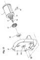
- FIG. 17 is an exploded perspective view showing the seat belt retractor of a third embodiment of the present invention.
- FIG. 18 is a side view showing only a motor and a power transmission gear mechanism used in the seat belt retractor shown in FIG. 17;
- FIGS. 19 ( a )- 19 ( c ) show a carrier used in the seat belt retractor shown in FIG. 17, wherein FIG. 19 ( a ) is a front view, FIG. 19 ( b ) is a cross sectional view taken along line 19 ( b )— 19 ( b ) of FIG. 19 ( a ), and FIG. 19 ( c ) is a rear view;
- FIG. 20 is an explanatory view illustrating the operation of the torque transmission limiting mechanism in the seat belt retractor shown in FIG. 17;
- FIGS. 21 ( a )- 21 ( c ) show a reduction pin used in the seat belt retractor shown in FIG. 17, wherein FIG. 21 ( a ) is a front view, FIG. 21 ( b ) is a longitudinal sectional view of FIG. 21 ( a ), and FIG. 21 ( c ) is a rear view;
- FIGS. 22 ( a ) and 22 ( b ) show a planetary gear used in the seat belt retractor of a fourth embodiment of the present invention, wherein FIG. 22 ( a ) is a front view, and FIG. 22 ( b ) is a cross sectional view taken along line 22 ( b )— 22 ( b ) of FIG. 22 ( a );
- FIGS. 23 ( a ) and 23 ( b ) show a carrier used in the seat belt retractor of the fourth embodiment, wherein FIG. 23 ( a ) is a front view, and FIG. 23 ( b ) is a longitudinal sectional view thereof;
- FIG. 24 is an explanatory view illustrating the operation of the torque transmission limiting mechanism of the seat belt retractor of the fourth embodiment
- FIG. 25 is a cross sectional view of a planetary gear used in the seat belt retractor, and a supporting pin of a fifth embodiment of the present invention.
- FIG. 26 is an explanatory drawing illustrating the operation of the torque transmission limiting mechanism in the seat belt retractor of the fifth embodiment
- FIG. 27 is a side view showing only a motor and a power transmission gear mechanism used in the seat belt retractor of a sixth embodiment of the present invention.
- FIGS. 28 ( a ) and 28 ( b ) show a connect gear used in the seat belt retractor of the sixth example shown in FIG. 27, wherein FIG. 28 ( a ) is a front view, and FIG. 28 ( b ) is a longitudinal sectional view;
- FIGS. 29 ( a ) and 29 ( b ) show an intermediate speed reducing gear used in the seat belt retractor of the sixth example shown in FIG. 27, wherein FIG. 28 ( a ) is a front view, and FIG. 28 ( b ) is a longitudinal cross sectional view thereof;
- FIGS. 30 ( a )- 30 ( c ) show parts of the endless belt used in the seat belt retractor of the sixth example shown in FIG. 27, wherein FIG. 30 ( a 1 ) to FIG. 30 ( c 4 ) show cross sectional views of the endless belts in various configurations, respectively;
- FIG. 31 shows a drawing of a seventh embodiment of the present invention.
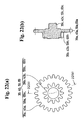
- FIG. 32 is a flow chart showing a driving control of the motor of the seventh embodiment shown in FIG. 31;
- FIG. 33 is a flow chart showing the driving control of the motor shown in an eighth embodiment of the invention.
- FIG. 34 is a flow chart showing the driving control of the motor shown in a ninth embodiment of the invention.
- FIG. 1 is an exploded perspective view of the seat belt retractor according to a first embodiment of the invention
- FIGS. 2 to 4 are partly enlarged exploded perspective views showing the seat belt retractor of FIG. 1
- FIG. 5 is a longitudinal sectional view of the seat belt retractor showing the assembled state as seen from a side of locking means
- FIG. 6 is a longitudinal sectional view of the seat belt retractor in the assembled state showing the side of the spring means.
- the seat belt retractor 1 of this embodiment comprises, in broadly dividing, a frame 2 , a reel 4 for winding the seat belt 3 , locking means 5 provided on one side of the frame 2 for preventing rotation of the reel 4 in the belt unwinding direction CW in use, a lock actuating mechanism 6 for actuating the locking means 4 when necessary, a force limiter mechanism (hereinafter referred to as EA mechanism) 7 for limiting the load applied to the seat belt when the unwinding of the seat belt is prevented by the action of the locking means 5 in the event of abrupt speed reduction, such as collision, speed reduction detecting means 8 for detecting the speed reduction of the vehicle, a motor 10 for generating a rotational torque, a power transmission gear mechanism 11 for transmitting a rotational torque of the motor 10 , a speed reducing mechanism 12 for reducing the speed of a rotational torque of the motor 10 transmitted from the power transmission gear mechanism 11 and transmitting it to the reel 4 , a power transmission path switching mechanism 13 for selectively switching to one
- the components of the seat belt retractor 1 are shown in three rows in the exploded perspective view in FIG. 1, actually, the end A 1 of the straight line passing through the centers of the upper locking means 5 and the lock actuating mechanism 6 respectively on the side of the locking means is connected or continues to the end A 1 of the straight line A 1 -A 2 passing through the frame 2 , and the end A 2 of the straight line passing through the centers of the lower speed reducing mechanism 12 and the spring means 14 respectively on the side of the speed reducing mechanism 12 is connected or continues to the end A 2 of the straight line A 1 -A 2 passing through the frame 2 .
- the frame 2 comprises a pair of parallel side walls 15 and 16 and a back plate 17 connecting the side walls 15 and 16 . Between both sidewalls 15 and 16 , there is disposed the reel 4 for winding the seat belt 3 .
- One of the side walls 15 is formed with a large circular opening 15 a .
- the other of the side walls 16 is also formed with a large circular opening 16 a concentrically with the large opening 15 a , and is fixed with an internal teeth member 18 having a circular opening with a prescribed number of internal teeth 18 a in the shape of ratchet teeth on the surface of the internal periphery thereof.
- the internal teeth 18 a are registered concentrically with respect to the large opening 16 a .
- the side wall 16 is further provided with a mounting hole for mounting the speed reduction detecting means 8 .
- the reel 4 comprises a seat belt winding portion 4 a for winding the seat belt 3 , flange portions 4 b and 4 c located on both ends of the seat belt winding portion 4 a , and a through hole 4 d that extends in the axial direction formed in the center thereof.
- the through hole 4 d is formed in such a manner that the end on the side of the side wall 15 is formed into the hexagonal shape in a cross section, and the end on the side of the sidewall 16 has a cross section that allows a stop 27 described later to be fitted and allows the reel 4 and the stop 27 to rotate together.
- the locking means 5 comprises a locking base 19 and a pawl 20 .
- the locking base 19 comprises a disk portion 19 a and a threaded shaft portion 19 b , and is provided with a through hole 19 c axially piecing the center thereof.
- the portion of the through hole 19 c at the disk portion 19 a has a shape of a regular hexagonal cross section 19 c ′.
- the disk portion 19 a is provided with a hole 19 d for rotatably supporting the pawl 20 , and an arc-shaped load-transmitted portion 19 e that is concentric with the hole 19 d .
- the load-transmitted portion 19 e receives a load from the pawl 20 .
- the disk portion 19 a is provided with a spring supporting portion 19 g for supporting one end of the pawl spring 25 described later.
- the pawl 20 includes a hole 20 a formed at the proximal end thereof, and rotatably mounted on the locking base 19 by fitting a fixture, such as a pin (not shown), into the hole 20 a and a hole 19 d formed on the locking base 19 .
- a fixture such as a pin (not shown)
- On the tip of the pawl 20 there is formed a stop claw 20 b engageable with the internal teeth 18 a of the internal teeth member 18 , and a cam follower 20 c formed of a protruding strut.
- the pawl 20 is formed with an arc-shaped load transmitting portion 20 d , which transmits the reaction acting on the pawl 20 b to the load-transmitted portion 19 e of the locking base 19 .
- the reaction of the pawl 20 b is supported by the locking base 19 .
- the lock actuating mechanism 6 comprises a lock gear 21 , a flywheel 22 , a flywheel spring 23 compressively mounted between the lock gear 21 and the flywheel 22 , a first retainer 24 removably fixed on the side wall 16 of the frame 2 , and a pawl spring 25 compressively mounted between the locking base 19 and the lock gear 21 .
- the lock gear 21 comprises a disk portion 21 a , and an annular teeth member 21 c having a prescribed number of the external teeth 21 b in the shape of ratchet teeth formed on the outer periphery thereof.
- a cylindrical boss 21 d In the center of the disk portion 21 a , there are formed a cylindrical boss 21 d and a supporting shaft 21 e protruding for rotatably supporting the flywheel 22 in the vicinity of the boss 21 d .
- first and second stops 21 f and 21 g for limiting the rotation of the flywheel 22 to a prescribed range, and a cam hole 21 h formed through the disk portion 21 a .
- the cam follower 20 c of the pawl 20 is fitted in the cam hole 21 h , so that the cam follower 20 c is guided to the cam hole 21 h to rotate the pawl 20 when the lock gear 21 is rotated with respect to the locking base 19 .
- the disk portion 21 a is provided with a spring supporting portion 21 i for supporting one end of the pawl spring 25 .
- the flywheel 22 is provided with a supporting hole 22 a rotatably fitted with the supporting shaft 21 e of the lock gear 21 , and a stopper portion 22 c formed with a stop claw 22 b on the tip thereof.
- the stopper portion 22 c is positioned between the first and the second stops 21 f and 21 g .
- the rotation of the flywheel 22 is limited to the portion between the first and second stops 21 f and 21 g , so that the stop claw 22 b takes the state retracted radially inside while the stopper portion 22 c is in contact with the first stop 21 f , and the stop claw 22 b takes the state projecting radially outside while the stopper portion 22 c is in contact with the second stop 21 g .
- the flywheel 22 is provided with a spring supporting portion 22 d for supporting one end of the flywheel spring 23 .
- the flywheel spring 23 is supported by the spring supporting portion 22 d of the flywheel 22 on one end and by the spring supporting portion (not shown) of the lock gear on the other end, so that the flywheel 22 is urged in the belt unwinding direction cw with respect to the lock gear 21 at all the time. Therefore, when the flywheel 22 is not in operation, the stopper portion 22 c remains in contact with the first stop 21 f.
- the first retainer 24 comprises a disk portion 24 a , a first annular flange portion 24 b formed on the outer periphery of the disk portion 24 a projecting toward the side, where the frame 2 resides, to be fixed removably on the side wall 16 (shown in FIG. 5 ), and a second annular flange portion 24 c formed on the outer periphery of the disk portion 24 a projecting toward the opposite side of the frame 2 .
- the center of the disk portion 24 a is formed with a through hole 24 d .
- the surface of the disk portion 24 a facing the frame 2 is provided with an annular teeth member 24 f having the internal teeth 24 e in the shape of ratchet teeth on the internal periphery and projecting concentrically with the through hole 24 d .
- the annular teeth member 24 f has a size so as to be inserted between the first and the second stops 21 f and 21 g .
- the stop claw 22 c of the flywheel 22 is also placed within the annular teeth member 21 c , so that the stop claw 22 c is engaged with the internal teeth 24 e when the flywheel 22 is rotated with respect to the lock gear 21 into the position in which the stop portion 22 c comes into contact with the second stop 21 g .
- the second annular flange portion 24 c is provided with a first cover 34 removably mounted thereon.
- the pawl spring 25 is supported by the spring supporting portion 21 i of the lock gear 21 on one end and by the spring supporting portion 19 g of the locking base 19 on the other end, so as to urge the lock gear 21 with respect to the locking base 19 in the belt unwinding direction CW at all the time. Therefore, when the lock gear 21 is not in operation, the cam follower 20 c of the pawl 20 is positioned at the innermost position 21 h 1 of the cam hole 21 h , and in this state, the lock gear 21 is prevented from further rotation caused by the pawl spring 25 .
- the EA mechanism 7 comprises a torsion bar 26 and a cylindrical stop 27 screwed onto a threaded shaft portion 19 b of the locking base 19 .
- the torsion bar 26 comprises a torsion bar portion 26 a , a first torque transmitting portion 26 b provided on one end of the torsion bar portion 26 a on the side of the lock gear 21 and having a regular hexagonal shape in a cross section to be fitted into the hole of regular hexagonal cross section 19 c ′ formed on the locking base 19 so as not to rotate with respect to the locking base 19 , a flange portion 26 c provided on the end of the first torque transmitting portion 26 b , a second torque transmitting portion 26 d with a regular hexagonal cross sectional shape provided on the other end of the torsion bar portion 26 a , a first shaft portion 26 f concentrically projecting from the second torque transmitting portion 26 d and formed with spline grooves 26 e on the tip thereof, and a second shaft portion 26 h
- the cylindrical stopper 27 is provided, on the inner periphery thereof, with a female screw 27 a to be screwed on the threaded shaft portion 19 b of the locking base 19 , and on the outer periphery thereof, with a pair of rotational torque transmitting portions 27 b and 27 c respectively for receiving rotational torque transmitted from the reel 4 .
- the stop 27 is rotatable with the reel 4 as an integral unit and axially movable with respect to the reel 4 .
- the EA mechanism 7 exerts its EA function that limits the belt load in the event of collision of the vehicle, and when the stop 27 comes into contact with the locking base 19 , the EA function is terminated.
- the region where the EA function is performed is defined by the stop 27 and its female screw 27 a , and the locking base 19 and its threaded shaft portion 19 b.
- the speed reduction detecting means 8 comprises a housing 28 to be mounted on the side wall 16 , a sensor case 29 to be mounted on the housing 28 , an inertial mass 30 to be mounted on the sensor case 29 , and an actuator 31 actuated by the inertial mass 30 .
- the housing 28 comprises a fitting portion 28 a for fixing to the side wall 16 of the frame 2 by fitting into the mounting hole 16 b formed therein, and a pair of supporting arm portions 28 b and 28 c for supporting the sensor case 29 .
- the sensor case 29 comprises a pair of supported portions 29 a and 29 b to be supported by engagement with the grooves formed on the supporting arm portions 28 b and 28 c , a mass mounting portion 29 c on which the inertial mass 30 is mounted, and a pair of supporting arms 29 d and 29 e for rotatably supporting the actuator 31 .
- the inertial mass 30 comprises a leg portion 30 a , a mass portion 30 b formed on the leg portion 30 a , and an operating portion 30 c for operating the actuator 31 .
- the inertial mass 30 mounted on the mass mounting portion 29 c is standing in an upright posture as shown in the figure in the normal state, and tilts in the direction ⁇ when the speed reduction more than the prescribed value is applied to the vehicle, so that the operating portion 30 c rotates the actuator 31 .
- the actuator 31 comprises an axle portion 31 a to be rotatably fitted into holes formed on a pair of supporting arm portions 29 d and 29 e of the sensor case 29 , a pressed portion 31 b to be pressed by the operating portion 30 c of the inertial mass 30 , and a stop claw 31 c provided on the opposite side of the axle portion 31 a and engageable with the external teeth 21 b of the lock gear 21 .
- the actuator 31 When the inertial mass 30 is in the upright posture, the actuator 31 is in the lowest position that is a non-engaged position in which the stop claw 31 c does not engage the external teeth 21 b , and when the inertial mass 30 tilts in the direction a, it rotates upwardly so as to take the engaged position in which the stop claw 31 c is engaged with the external teeth 21 b.
- the motor 10 can be mounted on the second retainer 35 that can be mounted to the left side wall 15 of the frame 2 .
- the second retainer 35 is provided with a thorough hole 35 a through which the axle 10 a of the motor 10 passes.
- the operation of the motor 10 is controlled by the CPU described above according to various information including information on the vehicle's travelling state, such as the speed of the vehicle or the acceleration of the vehicle, or to information on the vehicle's operating state, such as the speed of depression of the brake pedal or the speed of depression of the acceleration pedal.
- the power transmission gear mechanism 11 comprises a motor gear 36 formed as a helical gear mounted to the axle 10 a of the motor, and a connect gear 37 consisting of a large diameter connect gear 37 a formed as a helical gear and always engaging the motor gear 36 , and a small diameter connect gear 37 b formed concentrically and integrally therewith and having a diameter smaller than that of the large diameter connect gear 37 a.
- the speed reducing mechanism 12 comprises a first carrier 38 formed of an annular disk, two planetary gears 39 and 40 , two idle gears 41 and 42 , a sun gear 43 , a ring-shaped internal gear 44 , and a speed reducing gear 45 .
- the first carrier 38 is provided with a regular hexagonal through hole 38 a in the center thereof, and four supporting holes 38 b , 38 c , 38 d and 38 e formed at a regular interval in the peripheral direction.
- the planetary gears 39 and 40 comprise large planetary gears 39 a and 40 a both having large diameters respectively, and small planetary gears 39 b , 40 b both having smaller diameters than the large planetary gears 39 a and 40 a .
- the large planetary gears 30 a and 40 a and small planetary gear 39 b and 40 b are formed integrally and concentrically, and the small planetary gears 39 b and 40 b have the same dimensions as the idle gears 41 , 42 .
- the planetary gears 39 and 40 are respectively supported in two diametrically opposed supporting holes 38 b and 38 d formed on the first carrier 38 so as to rotate with respect to each other. In FIG. 1, small planetary gears 39 b and 40 b are not clearly shown.
- the idle gears 41 and 42 are supported in two other diametrically opposed supporting holes 38 c and 38 e formed in the first carrier 38 so as to rotate with respect to each other.
- the sun gear 43 is supported by the first shaft portion 26 f of the torsion bar 26 so as to rotate with respect to each other.
- the internal gear 44 has internal teeth 44 a on the inner periphery, and ratchet teeth 44 b on the outer periphery.
- the speed reducing gear 45 has internal teeth 45 a on the inner periphery, and external teeth 45 b on the outer periphery.
- the large planetary gears 39 a and 40 a of the two planetary gears 39 and 40 are respectively engaged with the sun gear at all the time and the small planetary gears 39 b and 40 b are engaged with the internal teeth 44 a of the internal gear 44 at all the time.
- the two idle gears 41 and 42 are engaged with the internal teeth 44 a of the internal gear 44 .
- the internal teeth 45 a of the speed reducing gear 45 are engaged with the sun gear 43 at all the time
- the external teeth 45 b of the speed reducing gear 45 are engaged with the small diameter connect gear 37 b of the connect gear 37 .
- the power transmission path switching mechanism 13 comprises a switch gear 46 , a plunger 47 , a spring 48 , and a stop lever 49 .
- the switch gear 46 is supported by the supporting shaft 50 mounted in the mounting hole 35 b of the second retainer 35 so as to rotate and move in the axial direction by a prescribed distance, and composed of a gear portion 46 a having a helical gear and an inclined surface 46 b in the shape of a truncated cone.
- the plunger 47 is slidably mounted in the cylinder housing 51 mounted on the second retainer 35 . In this case, the rotation of the plunger about the elongated axis is prevented by the projecting wall 47 a axially extending along the plunger 47 and slidably fitted into an elongated guide groove 51 of the cylinder housing 51 .
- the plunger 47 is provided on the tip thereof with a contact portion 47 c having an inclined surface 47 b of the same inclination as the inclined surface 46 b in the shape of the truncated cone.
- a spring 48 is compressively mounted between the plunger 47 and the cylinder housing 51 , and the spring force of the spring 48 urges the plunger 47 toward the switch gear 46 at all the time and brings the contact portion 47 c to contact with the switch gear at all the time. In this case, when the motor 10 is not in operation, as shown in FIG.
- the switch gear 46 is placed at the right position of the figure, and simultaneously the plunger 47 projects to the outer most position so that the front surface of the inclined surface 47 b of the contacting portion 47 c comes in contact with the front surface of the inclined surface 46 b of the switch gear 46 .
- These inclined surface 46 b and the inclined surface 47 b define the cam mechanism in which the plunger 47 is moved in accordance with the axial movement of the switch gear 46 .
- the plunger 47 is provided with a stop lever operating portion 47 d .
- the stop lever 49 comprises an axle 49 a , a bifurcated operating lever portion 49 b , and a stop claw 49 c .
- the axle 49 a is rotatably supported by the second retainer 35 .
- the branch portion of the operating lever portion 49 b is engaged with the stop lever actuating portion 47 d of the plunger 47 , and the plunger 47 allows the stop lever 49 to rotate about the axle 49 a .
- the stop claw 49 c is engaged with and released from the ratchet teeth 44 b of the internal gear 44 .
- the stop claw 49 c is placed to the position in which the stop claw 49 c is not engaged with the ratchet teeth 44 b as shown in FIG. 8, and when the plunger 47 is in the state shown in FIG. 7 ( d ), the stop claw 49 c is placed to the position engaging the ratchet teeth 44 b as shown in FIG. 9 .
- the power transmission path between the reel 4 and the motor 10 and comprising the power transmission gear mechanism 11 and the speed reducing mechanism 12 is set to the OFF-state in which the reel 4 and the motor are rotationally free with respect to each other, and when the motor 10 is in operation, it is set to the ON-state in which the reel 4 and the motor 10 are rotationally connected.
- the spring means 14 comprises a second cover 52 , a bush 53 , a return spring 54 , and a spring cover 55 .
- the second cover 52 is mounted to the second retainer 52 so as to cover the power transmission gear mechanism 11 , the speed reducing mechanism 12 , and the power transmission path switching mechanism 13 .
- An annular projection 52 a is provided on the second cover 52 on the opposite side of the speed reducing mechanism 12 , and a return spring 54 is received within the annular projection 52 a .
- a spring mounting portion 52 b is provided within the annular projection 52 a , and the second cover 52 is formed with a supporting hole 52 c for rotatably supporting the first shaft portion 26 f of the torsion bar 26 via a bush 53 .
- the bush 53 comprises a bearing portion 53 a and a spring mounting portion 53 b .
- the bush 53 is fitted by means of splines into the spline groove 26 e formed on the tip of the torsion bar 26 so as to rotate with the torsion bar 26 integrally.
- the bearing portion 53 a of the bush 53 is rotatably supported within the supporting hole 52 c formed in the second cover 52 , and supports the first shaft portion 26 f of the torsion bar 26 .
- a return spring 54 is formed as a flat spiral spring, and the outer periphery thereof is connected to the spring mounting portion 52 b of the second cover 52 and the inner periphery 54 b thereof is connected to the spring mounting portion 53 b of the bush 53 .
- the spring force of the return spring 54 urges the reel 4 in the belt winding direction CCW via the bush 53 and the torsion bar 26 at all the time.
- the second carrier 56 comprises a cylindrical first shaft portion 56 a of a regular hexagonal cross section, and a cylindrical second shaft portion 56 b (shown only in FIG. 6) having a regular hexagonal shape in a cross section at an outer periphery and a circular shape in a cross section at an inner periphery.
- the end of the through hole 4 d of the reel 4 on the side of the side wall 15 is fitted on the outer periphery of the first shaft portion 56 a so as not to rotate with respect to each other, and the second torque transmitting portion 26 d of the torsion bar 26 is fitted into the inner periphery of the first shaft portion 56 a so as not to rotate with respect to each other, so that the reel 4 , the second carrier 56 , and the second torque transmitting portion 26 d of the torsion bar 26 rotate integrally as an integral unit.
- the through hole 38 a of the first carrier 38 receives the outer periphery of the second shaft portion 56 n so as not to rotate with respect to each other, and the first shaft portion 26 f of the torsion bar 26 is fitted in the inner periphery of the second shaft portion 56 b , so that the first and second carriers 38 , 56 rotate as an integral unit.
- the second carrier 56 is axially fixed with respect to the second torque transmitting portion 26 d by means of an E-ring 57 mounted on the first shaft portion 26 f of the torsion bar 26 .
- the belt tension control mechanism for controlling the tension of the seat belt 3 is composed of the motor 10 , the power transmission gear mechanism 11 , the speed reducing mechanism 12 , the power transmission path switching mechanism 13 , and the CPU.
- the seat belt retractor 1 When the seat belt retractor 1 is in the non-operating mode, the seat belt 3 is wound on the reel 3 by the spring means 14 .
- the motor 10 is also in the non-operating mode. In this non-operating mode, as shown in FIG. 8, the motor gear 36 , the connect gear 37 , and the switch gear 46 do not rotate and, therefore, the switch gear 46 is placed at the position shown in FIGS. 7 ( a ) and 7 ( b ). Also, the plunger 47 projects to the outermost position so that the front surface of the inclined surface 47 b of the contacting portion 47 c contacts the front surface of the inclined surface 46 b of the switch gear 46 .
- the stop lever 49 is placed to the position in which the stop claw 49 c does not engage the ratchet teeth 44 b of the internal gear 44 , and the power transmission path is set to the OFF-state. Therefore, the internal gear 44 is free to rotate in any of the belt unwinding direction CW and the belt winding direction CCW, and thus the belt tension control mechanism is in the non-operating mode.
- the large planetary gears 39 a and 40 a of the planetary gears 39 and 40 tend to rotate respectively in the belt unwinding direction CW so as to rotate the sun gear 43 in the belt winding direction CCW
- the small planetary gears 30 b and 40 b tend to rotate in the belt-winding direction CCW so as to rotate the internal gear 44 in the belt unwinding direction CW.
- the sun gear 43 is engaged with the speed reducing gear 45 at all the time
- the speed reducing gear 45 is engaged with the small connect gear 37 b of the connect gear 37 at all the time
- the large diameter connect gear 37 a integrated with the small diameter connect gear 37 b is engaged with the motor gear 36 and the switch gear 46 at all the time.
- the sun gear 43 does not rotate, the rotation of the reel 4 in the belt unwinding direction CW during the unwinding operation of the seat belt 3 is not transmitted to the switch gear 46 , and thus the power transmission path switching mechanism 13 is not actuated. Also, the power transmission path between the reel 4 and the motor 10 remains in the OFF state, the rotation of the reel 4 is not transmitted to the motor 10 , and thus the motor is not affected by the rotation of the reel 4 . At this time, since the motor 10 is not driven, the belt tension control mechanism remains in the non-operating mode.
- the switch gear 46 rotates in the belt winding direction CCW at the same time.
- the switch gear since the large diameter connect gear 37 a of the connect gear 37 and the switch gear 46 are engaged by the helical engagement, the switch gear is subjected to a thrust force in the direction of axis. Then, the switch gear 46 is moved axially by this thrust force and placed to the left position shown in FIG. 7 ( d ). Concurrently, the inclined surface 47 b of the contacting portion 47 c of the plunger 47 slides along the inclined surface 46 b of the switch gear 46 with the axial movement of the switch gear 46 , and the plunger 47 moves away from the switch gear 46 and retracted into the cylinder housing 51 .
- the switch gear 46 Since the switch gear 46 is supported by the second retainer 35 in the thrusting direction, the switch gear 46 stops its axial movement and is placed in the left position as shown in FIG. 7 ( d ). In this state, as stated above, the plunger 47 is retracted into the cylinder housing to the inner most position so that the tip of the contacting portion 47 c contacts the outer periphery of the gear portion 46 a of the switch gear 46 . By this retracting action of the plunger 47 , as shown in FIG.
- the stop lever actuating portion 47 d presses the operating lever portion 49 b of the stop lever 49 , thereby rotating the stop lever 49 about the axle 49 a as is described above, so that the stop claw 49 c is placed at the position in which it can engage the ratchet teeth 44 b.
- the planetary gears 39 and 40 rotate on their axes by the driving torque of the motor 10 , when the internal gear 44 stops rotation, the planetary gears 39 and 40 rotate around the sun gear 43 along the internal teeth 44 a of the internal gear 44 in the belt winding direction CCW with the speed reduced. Therefore, the first and second carriers 38 and 58 rotate in the belt winding direction CCW at the speed of the planetary gears 39 and 40 rotating around the sun gear 43 , and the reel 4 rotates in the belt-winding direction CCW. In this manner, the reel 4 is rotated by the rotation of the motor 10 that is transmitted after being reduced in speed at a prescribed speed reduction ratio by the speed reducing mechanism 12 .
- the rotation of the reel 4 in the belt winding direction CCW forces the seat belt 3 to be wound onto the reel 4 by a rotational torque of the motor 10 , and thus the belt tension is controlled.
- the rotation amount of the reel 4 is detected by the rotary encoder 33 and supplied to the CPU.
- the CPU controls the motor 10 according to various information including information on the vehicle's travelling state, such as the speed of the vehicle or the acceleration of the vehicle, or to the vehicle's operating state, such as the speed of depression of the brake pedal or the speed of depression of the accelerating pedal to control the winding amount of the seat belt 3 , so that the belt tension is controlled to a preferred value.
- the switch gear 46 is rotated in reverse by the rotation of the connect gear 37 , the switch gear 46 is subjected to a thrust force in the direction reverse to the rotation described in (3) by the large connect gear 37 a since the large connect gear 37 a and the switch gear 46 are engaged by helical engagement. Then, the switch gear 46 moves from the state shown in FIG. 7 ( d ) to the right.
- the switch gear 46 and the plunger 47 take the non-operating mode as shown in FIG. 7 ( b ).
- the stop lever 49 is placed in the non-operating position, and comes to the non-engaging position in which the stop claw 49 c is not engaged with the ratchet teeth 44 b of the internal gear 44 . Consequently, the internal gear 44 is free to rotate and the reel 4 and the motor 10 are rotationally free with respect to each other.
- the tension of the seat belt 3 is controlled by the rotational torque of the motor 10 in the belt tension mechanism controlled by the CPU according to the state of the passenger in the vehicle, the operating mode outside the vehicle, or the operating condition of the seat belt 3 .
- the inertial mass 30 of the speed reduction detecting means 8 tilts forward to rotate the actuator 31 to the position in which the stop claw 31 c engages the external teeth 21 b of the lock gear 21 .
- the seat belt 3 tends to be drawn out by the forward inertia of the passenger.
- the reel 4 , the torsion bar 26 , the locking base 19 and the lock gear 21 tend to rotate together in the belt unwinding direction cw.
- the inertia of the passenger increases with the increase of the speed reduction of the vehicle.
- the torsion bar is twisted between the first and the second torque transmitting portions 26 b and 26 d to generate a rotational differential (relative rotation) between the reel 4 and the locking base 19 , thereby rotating only the reel 4 by a prescribed amount in the belt unwinding direction CW.
- the twist of the torsion bar 26 actuates the EA mechanism 7 to alleviate the impact applied to the passenger by the seat belt 3 .
- the reel 4 , the torsion bar 26 , the locking base 19 , and the lock gear 21 rotate together in the belt unwinding direction CW as stated above.
- the flywheel 22 rotates together with the lock gear 21 , and the lock gear 21 does not rotate with respect to the flywheel 22 .
- the flywheel 22 experiences a delay in the rotation, and rotates with respect to the lock gear 21 .
- the stop claw 22 c of the flywheel 22 comes to the position to engage the internal teeth 24 e of the retainer 24 , and the further rotation of the lock gear 21 allows the stop claw 22 c to engage the internal teeth 24 e of the retainer 24 , and the further rotation of the lock gear 21 in the belt unwinding direction CW is prevented.
- the rotation of the lock gear 21 in the belt unwinding direction CW is prevented, the rotation of the reel 4 in the belt unwinding direction CW is also prevented as in the case of the abrupt speed reduction described above. In this way, the abrupt unwinding of the seat belt 3 is prevented.
- the control of the tension of the seat belt 3 may be carried out reliably and easily by a rotational torque by controlling the rotation of the reel 4 of the motor via the power transmission gear mechanism 11 and the speed reducing mechanism 12 .
- the ON and OFF-states of the power transmission path between the reel 4 and the motor 10 is controlled by the power transmission path switching mechanism 13 that is operated by the rotational torque of the motor 10 , it is not necessary to use a specifically designed actuator using other motive power, such as electromagnetic solenoid or the like, for actuating the power transmission path switching mechanism 13 . Therefore, the number of the components of the power transmission path switching mechanism may be reduced, thereby simplifying the structure thereof and further reducing the cost.
- FIG. 10 is an exploded perspective view showing the seat belt retractor according to another embodiment of the invention.
- FIG. 11 to FIG. 13 are partly enlarged exploded perspective views;
- FIG. 14 is a partly broken side view of a motor, a power transmission gear mechanism, a speed reducing mechanism, and a power transmission path switching mechanism used in the seat belt retractor shown in FIG. 10 in the non-operating mode;
- FIG. 15 is a side view as in FIG. 14 showing the state in which the seat belt is wound by a driving force of the motor;
- FIG. 16 is a side view as in FIG. 14 showing the state in which the winding operation of the seat belt is released.
- like reference numerals are used for components identical to those in the previous embodiment, and the detailed description is omitted.
- the seat belt retractor of the following embodiments only the parts different from those of the previous embodiment will be described and the description of the parts identical to those of the previous embodiment will be omitted.
- the motor 10 of the seat belt retractor 1 of the second embodiment is mounted on the upper part of the retractor 1 .
- an intermediate speed reducing gear 58 comprising a large diameter intermediate speed reducing gear 58 a and a small diameter intermediate speed reducing gear 58 b formed as an integral unit is placed between the connect gear 37 and the speed reducing gear 45 in the power transmission mechanism 11 and the speed reducing mechanism 11 of the second embodiment.
- the small diameter connect gear 37 b of the connect gear 37 is engaged with the large diameter intermediate speed reducing gear 58 a of the intermediate speed reducing gear 58 at all the time, and the small diameter intermediate speed reducing gear 58 b of the intermediate speed reducing gear 58 is engaged with the external teeth 45 b of the speed reducing gear 45 at all the time, so that the rotational speed of the connect gear 37 is reduced via the intermediate speed reducing gear 58 and transmitted to the speed reducing gear 45 .
- the adequate number (one or more) of the intermediate gears may be added between the connect gear 37 and the speed reducing gear 45 , otherwise the intermediate gear may be omitted.
- the first carrier 38 is provided with three planetary gears 39 , 40 and 59 so as to rotate about their own axes.
- these planetary gears 39 , 40 , and 59 are mounted to the first carrier 38 by reduction pins 61 , 62 and 63 via a reduction plate 60 .
- the planetary gears 39 and 40 comprise large and small planetary gears having two different diameters respectively, i.e.
- the planetary gears 39 , 40 and 59 of the second embodiment are formed of planetary gears having the same diameters with respect to each other.
- the planetary gears with the same diameters are engaged with both of the sun gear 43 and the internal teeth 44 a of the internal gear 44 at all the time.
- the number of the planetary gears is not limited to three, but it may be two as in the first example, and may be four as in a third embodiment described later. Namely, the planetary gear may be any suitable number but at least one. The adequate number of the idle gears, such as the idle gears 41 and 42 in the first embodiment, may be provided as well.
- the speed reducing plate 60 may be omitted as in the first embodiment.
- the planetary gears 39 , 40 and 59 may be composed of large and small planetary gears having two different diameters as in the first embodiment.
- the power transmission path switching mechanism 13 of the first embodiment is formed of the switch gear 46 , the plunger 47 , the spring 48 , the stop lever 49 , the supporting shaft 50 , and the cylinder housing 51
- the power transmission path switching mechanism 13 of the second embodiment comprises, as shown in FIG. 10 and FIG. 12, a stop lever 49 , a spring-holding member 64 integrally and coaxially assembled to the connect gear 37 that is rotatably supported by the retainer so as to rotate with the connect gear 37 as an integral unit, and a lever spring (corresponding to the control lever of the invention) 65 having a prescribed resiliency and integrally assembled to the spring-holding member 64 on one end so as to rotate with the spring-holding member 64 as an integral unit and connected to the stop lever 49 on the other end.
- the lever spring 65 is assembled to the spring-holding member 64 by disposing the bent portion 65 a of the lever spring 65 around the outer periphery of the spring-holding member 64 , and fitting the same between the two projections 64 b of the spring-holding member 64 and the connector gear 37 with prescribed friction in the direction of rotation.
- the stop lever 49 is provided on the second retainer 35 so as to be brought into and out of contact with the ratchet teeth 44 b of the internal gear 44 by a parallel movement.
- the locking base 19 is provided on one end of the torsion bar portion 26 a of the torsion bar 26 integrally with the torsion bar 26 . Therefore, in the second embodiment, the first torque transmitting portion 26 b of the torsion bar portion 26 a is not provided as in the first embodiment. It is also possible to provide the torsion bar portion 26 a and the locking base 19 as separate pieces, and the torsion bar portion 26 a and the locking base 19 rotate as an integral unit via the first torque transmitting portion 26 b provided on the torsion bar portion 26 a as in the first embodiment.
- a cylindrical stop 27 of the EA mechanism 7 and the male screw 19 b formed on the locking base 19 to engage the female screw 27 a of the stop 27 are not provided as shown in the first embodiment. Therefore, the reel 4 and the locking base 19 rotate with respective to each other but not as a single piece as a result of twisting action of the torsion bar 26 .
- the torsion bar 26 is not provided with the first shaft portion 26 f that is provided on the distal side of the second torque transmitting portion 26 d in the first embodiment, and the reel 4 is not axially cut as in the first embodiment.
- the second carrier 56 described in the previous embodiment is not provided. Therefore, the second torque transmitting portion 26 d of the torsion bar 26 is directly fitted to the through hole 4 d of the reel 4 from the end on the side of the side wall 15 so as not to rotate with respect to each other, and an axial engagement between the supporting pin 66 radially inserted into the reel 4 and the side portion of the second torque transmitting portion 26 d prevents the torsion bar 26 from coming off in the axial direction. Because the supporting pin 66 is provided, the E-ring 57 described in the first embodiment is not provided.
- the reel 4 of the second embodiment is provided with the first shaft portion 4 e , the second shaft portion 4 f having a diameter smaller than that of the first shaft portion 4 e , and the third shaft portion 4 g having a diameter smaller than that of the second shaft portion 4 f aligning in this order so as to extend its length toward the tip.
- the first shaft portion 4 e is provided with the first carrier 38 fitted thereto by means of splines so as to rotate with the first shaft portion 4 e as an integral unit (in other words, to rotate with the reel 4 as an integral unit), and the sun gear 43 is supported thereon so as to rotate with respect to each other.
- the sun gear 43 is engaged with the internal teeth 45 a of the speed reducing gear 45 at all the time as in the first embodiment.
- the second shaft portion 4 f is connected to an output shaft of the pretensioner cassette 67 (not shown) and the bearing 68 , both being fitted by means of splines, so as to rotate with the second shaft portion 4 f as an integral unit (in other words, so as to rotate with the reel 4 as an integral unit), and the second shaft portion 4 f is rotatably supported in the axial hole 67 of the housing 67 a of the pretensioner cassette 67 by means of the bearing 68 .
- the pretensioner cassette 67 comprises a pretensioner accommodated within a housing 67 a . Since the pretensioner is known in the art, and is not directly related to the invention, the detailed description is omitted. However, to be brief, the pretensioner is a device that is actuated in case of emergency such as a collision of the vehicle and winds a prescribed amount of the seat belt 3 by rotating the reel 4 in the seat belt winding direction CCW to apply a prescribed pretension to the seat belt in advance.
- the seat belt retractor 1 of this embodiment includes the pretensioner cassette 67 , however, it is needless to say that the invention is also applicable to the seat belt retractor 1 having no pretensioner.
- the third shaft portion 4 g is fitted with a bush 53 of the spring means 14 , which is not shown in the figure, so as to rotate as an integral unit as in the first embodiment.
- the motor is controlled by the CPU according to various information including information on the vehicle's traveling state, such as the speed of the vehicle and the acceleration of the vehicle, or to information on the vehicle's operating state, such as the speed of depression of the brake pedal or the speed of depression of the accelerating pedal.
- the seat belt retractor 1 When the seat belt retractor 1 is in the non-operating mode, the seat belt 3 is wound on the reel 3 by the spring means 14 .
- the motor 10 is also in the non-operating mode.
- the stop lever 49 In this non-operating mode, since the motor gear 36 and the connect gear 37 do not rotate, as shown in FIG. 14, the stop lever 49 is placed to the non-operating position in which the stop claw 49 c is not engaged with the ratchet teeth 44 b of the internal gear 44 , and the power transmitting path is set to the OFF-state. Therefore, the internal gear 44 is free to rotate in either of the belt-unwinding direction CW and the belt-winding direction CCW, and thus the belt tension control mechanism is in the non-operating condition.
- the power transmission path extending through the motor gear 36 , the connect gear 37 , the intermediate speed reducing gear 58 , and the speed reducing gear 45 requires a force (torque) equal to or higher than a given value for rotating these gears by a torque held by the motor 10 in the non-operating mode.
- the reel 4 Since the reel 4 is unwound in the belt unwinding direction CW when the seat belt 3 is unwound or withdrawn from the non-operating mode of the seat belt retractor as stated above, the second torque transmitting portion 26 d of the torsion bar 26 rotates in the belt unwinding direction CW. Then, the first carrier 38 rotates in the same direction CW, and the planetary gears 39 , 40 and 59 tend to rotate around the sun gear 43 respectively in the same direction CW.
- the sun gear 43 is engaged with the speed reducing gear 45 at all the time, and the speed reducing gear 45 is engaged with the small diameter intermediate speed reducing gear 58 b of the intermediate speed reducing gear 58 at all the time, and thus a prescribed force is required to rotate the intermediate speed reducing gear 58 as stated above. Therefore, while the sun gear 43 is applied with a rotational resistance, the internal gear 45 is free to rotate as stated above. In other words, the internal gear 45 rotates freely and the sun gear does not rotate. In this situation, all of the planetary gears 39 , 40 and 59 become rotatable in the belt unwinding direction CW.
- the power transmission path switching mechanism 13 is not actuated, and the power transmission path between the reel 4 and the motor 10 remains in the OFF-state, so that the rotation of the reel 4 is not transmitted to the motor 10 , and the motor is not affected by the rotation of the reel 4 . Since the motor 10 is not actuated in this state, the belt tension control mechanism is held in the non-operating mode.
- the stop claw 49 c takes the engaging position in which it is engageable with the ratchet teeth 44 b of the internal gear 44 .
- the lever spring 65 can not rotate in the direction CCW any more, but a slip is generated between the connect gear 37 and the lever spring 65 , thereby rotating the connect gear 37 with respect to the lever spring 65 .
- the motor 10 continues to rotate.
- the rotation of the reel 4 in the belt winding direction CCW forces the seat belt 3 to be wound up on the reel 4 by the rotational torque of the motor 10 , and the belt tension is controlled.
- the motor 10 is controlled based on the vehicle's traveling state or the vehicle's operating state, and the winding amount of the seat belt 3 is controlled to the desired amount, thereby controlling the belt tension to a desired value.
- the seat belt retractor 1 of the second embodiment is constructed in such a manner that the belt tension of the seat belt 3 is controlled by a rotational torque of the motor 10 in the belt tension mechanism controlled by the CPU, according to the state of the passenger in the vehicle, the operating condition outside the vehicle, or the operating condition of the seat belt 3 .
- the power transmission path switching mechanism 13 is comprised of only three members of the spring-holding member 64 , the lever spring 65 , and the stop lever 49 , the number of the components constituting the power transmission path switching mechanism 13 is reduced and thus the mechanism is simplified in comparison with the first embodiment. Therefore, the power transmission is carried out reliably, thereby ensuring reliable and easy control of the belt tension of the seat belt 3 .
- the movement of the stop lever 49 is smooth and more reliable, and the impact to the internal gear 44 of the stop lever 49 in the event of collision or the like is alleviated.
- the power transmission path switching mechanism 13 of the second embodiment may be applied to the seat belt retractor 1 of the type as described in the first embodiment, wherein the torsion bar 26 passes through the reel 4 in the direction of the axis, and the power transmission path switching mechanism 13 of the first embodiment may be applied to the seat belt retractor 1 of this embodiment wherein the torsion bar 26 does not pass through the reel 4 in the direction of the axis.
- FIG. 17 is an exploded perspective view showing the seat belt retractor of a third embodiment of the present invention
- FIG. 18 is a side view showing only a motor and a power transmission gear mechanism used in the seat belt retractor shown in FIG. 17 .
- the motor 10 is located on the lower portion of the retractor as in the first example shown in FIG. 1 .
- planetary gears 39 , 40 , 59 and 69 are mounted on the first carrier 38 by four reduction pins 61 , 62 , 63 and 70 respectively, so as to rotate about their own axes. More specifically, as shown in FIGS. 19 ( a ) and 19 ( b ), planetary gear mounting portions 71 , 72 , 73 and 74 formed with female screws 71 a , 72 a , 73 a and 74 a respectively, which correspond to a transmitted torque limiting mechanism of the invention and a supporting portion of the planetary gear of the present invention, are provided on one side surface of the first carrier 38 circumferentially at regular intervals so as to project in the direction of the axis.
- These planetary gear mounting portions 71 , 72 , 73 and 74 are constructed such that they are ruptured from the roots thereof when a shearing force equal to or exceeding a prescribed value is applied in the direction of rotation of the carrier 38 , as shown in FIG. 20 .
- spline grooves to which the first shaft portion 4 e of the reel 4 is spline-fitted are formed on the other side surface of the first carrier 38 .
- the four reduction pins 61 , 62 , 63 and 70 are identical, and each of them comprises, as shown in FIGS. 21 ( a ) to 21 ( c ), a head portion 76 , a male screw 77 vertically extending from the head portion 76 , and a tool hole 78 for inserting a tool, such as a screw driver, and engaging the same in the direction of rotation for rotating the reduction pins 61 , 62 , 63 and 70 .
- the respective planetary gears 39 , 40 , 59 and 69 are mounted on the first carrier 38 by screwing the male screw 77 of the reduction pins 61 , 62 , 63 and 70 into the female screws 71 a , 72 a , 73 a and 74 a of the first carrier 38 via the reduction plate 60 .
- the reduction pins 61 , 62 , 63 and 70 may be mounted on the planetary gear mounting portions 71 , 72 , 73 and 74 , respectively, of the first carrier 38 by fixing means other than screwing, such as press-fitting or swaging. In such an arrangement, screw thread cutting on the male screw 77 or female screws 71 a , 72 a , 73 a and 74 a is not necessary, and thus machining is simplified.
- the planetary gears 39 , 40 , 59 and 69 are identical, and engaged with both the sun gear 43 and the inner teeth 44 a of the internal gear 44 at all the time. It is possible to provide the adequate number, that is, one or more of the planetary gears. It is also possible to provide the adequate number of idle gears, such as the idle gears 41 , 42 in the first embodiment. In addition, the reduction plate 60 may be omitted as in the first example.
- Each of the planetary gears 39 , 40 , 59 and 69 of the third embodiment may be composed of a large planetary gear and a small planetary gear having two different diameters respectively as in the first embodiment.
- the locking base 19 and the torsion bar 26 of the second embodiment shown in FIG. 10 are formed as a single unit, the locking base 19 and the torsion bar 26 in the third embodiment are formed separately as in the first embodiment, and the first torque transmission part 26 b of the torsion bar 26 is fitted into the engaging hole 19 h formed at the center of the locking base 19 in such a manner that they can not rotate with respect to each other, whereby the torsion bar 26 and the locking base 19 are rotatively connected.
- the locking base 19 includes a shaft 19 i projecting from the center of the surface thereof on the opposite side of the engaging hole 19 h , and rotatably penetrating through the components 21 and 24 .
- a bush 53 to which the inner end of the return spring is connected is fitted so that they can rotate together as a single unit.
- the retractor 1 of the third embodiment has substantially the same structure as the second embodiment except that the pretensioner cassette 67 is not provided.
- the motor 10 when an abrupt deceleration is applied to the vehicle in case of an emergency, such as collision, the motor 10 is actuated to wind the prescribed amount of the seat belt 3 in advance to restrain the passenger.
- the passenger tends to move forward by the inertia, but is prevented from being moved forward and thus protected more effectively since a force of the seat belt 3 to restrain the passenger has been increased.
- the seat belt retractor 1 of the third embodiment in case a large torque, in other words, a large shearing force of the prescribed value or more is applied in the direction of rotation to the four planetary gear mounting portions 71 , 72 , 73 and 74 standing on the carrier 38 , the four planetary gear mounting portions 71 , 72 , 73 and 74 are ruptured at their root portion as shown in FIG. 20 . Therefore, increase in the EA load due to the load of the motor 10 itself is controlled or suppressed.
- FIGS. 22 ( a ) and 22 ( b ) show the fourth embodiment of the present invention.
- the respective planetary gears 39 , 40 , 59 and 69 are mounted on the four planetary gear mounting portions 71 , 72 , 73 and 74 , respectively, by the respective reduction pins 61 , 62 , 63 and 70 so that the respective planetary gear mounting portions 71 , 72 , 73 and 74 are ruptured when a sharing force of the preset value or more is applied thereto.
- the planetary gear is provided with an integrated axis of rotation, which is rotatably mounted on the carrier 38 and constructed in such a manner that it is ruptured at its root when subjected to a sharing force equal to or higher than the prescribed value in the direction of rotation.
- the respective planetary gears 39 , 40 , 59 and 69 of the fourth embodiment are composed of large planetary gears 39 a , 40 a , 59 a , 69 a and small planetary gears 39 b , 40 b , 59 b , 69 b , respectively. It is needless to say that the construction of the planetary gears is not limited to this type, but the planetary gears 39 , 40 , 59 and 69 of the third embodiment may be used as well. As shown in FIG.
- the carrier 38 of the fourth embodiment is formed with four through holes 79 , 80 , 81 and 82 circumferentially at regular intervals. Then, the respective planetary gears 39 , 40 , 50 and 69 are rotatably mounted on the carrier 38 by fitting the axes of rotation 39 c , 40 c , 59 c and 69 c of the respective planetary gears 39 , 40 , 59 and 69 into the through holes 79 , 80 , 81 and 82 .
- the axes of rotation 39 c , 40 c , 59 c and 69 c are constructed in such a manner that they are ruptured at their root portions when subjected to a sharing force equal to or higher than the preset value in the direction of rotation.
- the axes of rotation 39 c , 40 c , 59 c and 69 c of the respective planetary gears 39 , 40 , 59 and 69 are subjected to a sharing force equal to or higher than the prescribed value as in the case described above, the respective axes of rotation 39 c , 40 c , 59 c and 69 c are ruptured at the root portions thereof as shown in FIG. 24 . Therefore, increase in the EA load due to the load of the motor 10 itself is controlled or suppressed.
- the respective axes of rotation 39 c , 40 c , 59 c and 69 c provided on the respective planetary gears 39 , 40 , 59 and 69 are rotatably fitted into the through holes 79 , 80 , 81 and 82 of the carrier 38 so that the respective axes of rotation 39 c , 40 c , 59 c and 69 c are ruptured when subjected to a sharing force equal to or higher than the preset value in the direction of rotation
- the supporting pins passing through the planetary gears to rotatably support the planetary gears are secured to the carrier so that the supporting pins are ruptured when subjected to a sharing force equal to or higher than the prescribed value in the direction of rotation.
- the centers of the respective planetary gears 39 , 40 , 59 and 69 of the fifth embodiment are provided with through holes 39 d , 40 d , 59 d and 69 d respectively.
- the supporting pins 83 , 84 , 85 and 86 which correspond to the torque transmission limiting mechanism and the supporting portion for the planetary gear of the invention, having head portions 83 a , 84 a , 85 a and 86 a pass through these through holes 39 d , 49 d , 59 d and 69 d , and the other ends thereof are fitted and fixed to the through holes 79 , 80 , 81 and 82 of the carrier 38 shown in FIGS. 23 ( a ) and 23 ( b ).
- each of the head portions 83 a , 84 a , 85 a , and 86 a is larger than the diameter of each of the through holes 39 d , 40 d , 59 d and 69 d .
- the respective planetary gears 39 , 40 , 59 and 69 are prevented from being detached by the head portions 83 a , 84 a , 85 a , 86 a of the supporting pins 83 , 84 , 85 and 86 , and these supporting pins 83 , 84 , 85 and 86 are constructed in such a manner that they are ruptured when subjected to a sharing force equal to or higher than the preset value in the direction of rotation.
- the respective supporting pins 83 , 84 , 85 and 86 are subjected to a sharing force equal to or higher than the prescribed value as in the case described above, the respective supporting pins 83 , 84 , 85 and 86 are ruptured as shown in FIG. 26 . Therefore, increase in the EA load caused by the load of the motor 10 itself is controlled or suppressed.
- FIG. 27 is a side view showing only the motor and the power transmission gear mechanism of a sixth embodiment of the present invention, shown in the same manner as in FIG. 18 .
- the power transmission between the connect gear 37 and the intermediate speed reducing gear 58 is made by a belt power transmission mechanism 87 in the seat belt retractor 1 of the sixth embodiment.
- a connect gear 37 is composed of a large diameter connect gear 37 a , and a small diameter belt pulley 37 c formed coaxially and unitarily therewith, and having a smaller diameter than the large connect gear 37 a .
- an intermediate speed reducing gear 58 is composed of a small intermediate speed reducing gear 58 b , and a large diameter belt pulley 58 c formed coaxially and unitarily therewith, and having a larger diameter than the small diameter intermediate speed reducing gear 58 b .
- An endless belt 88 is looped between the large diameter belt pulley 58 c and the small diameter belt pulley 37 c .
- the belt power transmission mechanism 87 is composed of the small diameter belt pulley 37 c , the large diameter belt pulley 58 c , and the endless belt 88 .
- These small diameter belt pulley 37 c , the large diameter belt pulley 58 c , and the endless belt 88 correspond to the torque transmission limiting mechanism of the invention.
- the frictional coefficient between the small diameter belt pulley 37 c and the endless belt 88 , and the frictional coefficient between the large diameter belt pulley 58 c and the endless belt 88 are set to the values such that a slip occurs between them when a torque transmitted among the respective belt pulleys 37 c , 58 c and the endless belt 88 is equal to or higher than the prescribed value.
- transmission of a power from the belt pulleys 37 c , 58 c to the endless belt 88 , or transmission of a power from the endless belt 88 to the belt pulleys 37 c , 58 c is discontinued, and when a torque is below the prescribed value, the power is transmitted.
- the endless belt 88 may have various configurations. As examples of the configurations of the endless belts 88 , as shown in FIG. 30 ( a ), both of the inner and outer side surfaces 88 a and 88 b may be smoothly formed, and the configurations of the cross sections may be a circle as shown in FIG. 30 ( a 1 ), an inverted trapezoid as shown in FIG. 30 ( a 2 ), a rectangle as shown in FIG. 30 ( a 3 ), and inversed triangle as shown in FIG. 30 ( a 4 ). It may be an oval, as well.
- the endless belt 88 may have semi-circular projections 88 c , 88 d on the inner and outer side surfaces 88 a and 88 b , and the configurations of the cross sections may be a circle as shown in FIG. 30 ( b 1 ), an inverted trapezoid as shown in FIG. 30 ( b 2 ), a rectangle as shown in FIG. 30 ( b 3 ), and an inversed triangle as shown in FIG. 30 ( b 4 ). It may be an oval, as well.
- rectangular projections 88 c , 88 c may be formed.
- the projections on the inner and outer side surfaces 88 c , 88 d may be formed at the same position, the projections 88 c , 88 d may be formed alternately in a staggered arrangement on the inner and outer side surfaces 88 a , 88 b.
- rectangular projections 88 c may be formed only on the inner side surface 88 a as shown in FIG. 30 ( c ), and the configurations of the cross sections may be a circle as shown in FIG. 30 ( c 1 ), an inverted trapezoid as shown in FIG. 30 ( c 2 ), a rectangle as shown in FIG. 30 ( c 3 ), and inversed triangle as shown in FIG. 30 ( c 4 ). It may be an oval, as well.
- semi-circular projections 88 c may be formed.
- the large diameter connect gear 37 a is engaged with the motor gear 36 all the time
- the small diameter intermediate speed reducing gear 58 b is engaged with the speed reducing gear 45 all the time.
- increase in the EA load is not controlled by rupturing the supporting portion of the planetary gear when subject to the EA lead due to the load of the motor 10 itself as in the third to fifth embodiment, so that when the EA load due to the load of the motor 10 is lowered, it may be used repeatedly. Therefore, in the vehicle that can be driven freely even after occurrence of an emergency, such as a crush, when another emergency, such as a secondary crash, occurs again while the vehicle is being driven to another location, such as a repair shop, the capability of the seat belt retractor to restrain the passenger by winding its seat belt by the motor may be fully exerted again.
- an emergency such as a crush
- another emergency such as a secondary crash
- transmission of the power between the connect gear 37 and the intermediate speed reducing gear 58 is made by the belt power transmission mechanism 87 in the sixth embodiment
- transmission of the power between the motor gear 36 and the connect gear 37 may be made by the belt power transmission mechanism.
- transmission of the power between the motor gear 36 and the intermediate speed reducing gear 58 may be made by the belt transmission mechanism.
- an intermediate pulley comprising a large diameter pulley and a small diameter pulley corresponding to the connect gear 37 may be provided between the motor gear 36 and the intermediate speed reducing gear 58 .
- the passenger is restrained by the seat belt 3 wound by the prescribed amount by the rotation of the motor 10 in the belt winding direction CCW in case of an emergency. Therefore, after the emergency state is eliminated, the seat belt 3 is restored to its original state, i.e. state before occurrence of an emergency, by rotating the motor in the belt unwinding direction CW.
- the reel 4 can not be rotated easily in the belt unwinding direction CW because the locking means 5 is actuated and the pawl 20 is engaged with the inner teeth 18 a of the internal teeth member 18 fixed on the frame 2 , which resists restoration of the seat belt 3 to its original state. Therefore, the passenger is released by detaching a tongue, not shown, from the buckle.
- the seat belt retractor that ensures restoration of the seat belt 3 to its original state only by controlling the motor 10 without detaching the tongue from the buckle every time after the elimination of the emergency state. Therefore, according to the invention, the seat belt 3 is restored more reliably to its original state by the driving power of the motor 10 after the emergency state is eliminated.
- FIG. 31 shows a seventh embodiment of the present invention, wherein the seat belt 3 is restored more reliably to its original state by the driving power of the motor after the emergency state is eliminated.
- the seat belt retractor 1 of the seventh embodiment has a feature in the driving control of the motor, and any of the seat belt retractors 1 of the previous embodiments may be used.
- a CPU is provided with vehicle's emergency state detecting means, not shown.
- the vehicle's emergency state detecting means measures a time period (t 2 ⁇ t 1 ) from the time t 1 when the brake pedal reached the first fixed depressing position from the initial position, until the time t 2 when the brake pedal reached the second fixed depressing position. Then, when the time described above (t 2 ⁇ t 1 ) is equal to or below a certain value, in other words, when the driver brakes suddenly, the vehicle's emergency state detecting means determines that there is a danger of a crush to an obstacle, such as a vehicle, in front thereof, and outputs a signal to the motor drive control means, not shown, in the CPU.
- the motor drive control means restrains the passenger by rotating the motor in the belt winding direction CCW for the first preset time period T 1 according to the output signal received from the vehicle's emergency state detecting means, and winding a prescribed amount of seat belt 3 .
- vehicle's emergency state detecting means uses information on the state of operation by the driver or on the traveling state of the vehicle that may be generated when there is a danger of a crush, for example by determining whether the vehicle's deceleration is equal to or below the preset deceleration or not, as well as by determining whether the time (t 2 ⁇ t 1 ) is equal to or below a certain time period or not as is described above.
- the operation of the motor is stopped.
- the speed reduction detecting means 8 is actuated, and the pawl 20 of the locking means 5 of the seat belt retractor 1 is moved to the position where it is engageable with the internal teeth 18 a as described above, and then, the seat belt is unwound by the passenger firmly restrained onto the seat of the vehicle by the driving force of the motor and the elasticity of the seat itself, so that the reel 4 is rotated in the belt unwinding direction CW.
- the pawl 20 is engaged with the internal gear 18 a , so that the rotation of the reel 4 in the belt unwinding direction CW is prevented.
- the locking means 5 is actuated. Therefore, the unwinding of the seat belt 3 is prevented, thereby preventing the inertial movement of the passenger effectively.
- the motor 10 is rotated for the third preset time period T 3 in the belt unwinding direction CW as in the conventional case, and the seat belt 3 and the seat belt retractor 1 are returned to the normal state where the normal unwinding and winding of the seat belt 3 is possible, that is, the state before the vehicle comes into the emergency state with the above described time period (t 2 ⁇ t 1 ) equal to or below a certain time period.
- the motor 10 is driven and rotated in the belt winding direction CCW at the step S 2 .
- the step 3 after the motor 10 is actuated, it is determined whether or not the first preset time period T 1 has elapsed.
- the motor 10 is stopped at the step S 4 .
- the step S 5 it is determined whether or not the speed of the vehicle has become zero and the vehicle 10 has stopped.
- the motor 10 is rotated again in the belt winding direction CCW at the step S 6 .
- the operation of the locking means 5 can be released automatically. Therefore, the passenger can be released easily and reliably from the state securely restrained by driving the motor 10 in the belt winding direction CCW. In addition, it is not necessary to detach the engagement between the tongue and the buckle every time as in the conventional manner, so that the passenger need not perform cumbersome lock releasing operation.
- the motor 10 is driven intermittently for the first preset time period T 1 and for the second preset time period T 2 .
- the motor 10 may be driven continuously until the second preset time T 2 has elapsed from the moment that the vehicle's emergency state is detected. In this case, it is not necessary to set the first preset time period T 1 .
- FIG. 33 is a flow chart showing a driving control of a motor shown in an eighth embodiment of the invention.
- a driving control of the motor of the eighth example is also intended to restore the seat belt 3 to its original state by the driving force of the motor 10 after the elimination of the emergency state as in the case of the seventh embodiment shown in FIG. 31 and FIG. 33 described above.
- the motor 10 is controlled to wind the seat belt when one of the conditions according to information on the state of operation by the driver, or information on the vehicle's traveling state is satisfied, in other words, when the time period which takes for the brake pedal to move from the first fixed depressing position to the second fixed depressing position is equal to or below the preset fixed time period, that is, when the speed of depression of the brake pedal is equal to or higher than the preset fixed speed, or when the deceleration of the vehicle is equal to or higher than the preset fixed deceleration.
- the vehicle is determined to be in the emergency state only when all of these three conditions are satisfied.
- the motor 10 is driven to wind the seat belt 3 to restrain the passenger with a relatively strong restraining force.
- the motor 10 is driven in the belt winding direction for the second preset time period T 2 upon stoppage of the vehicle, and then, in the belt unwinding direction for the third preset time period T 3 , so that the seat belt 3 is restored to the original state as it was, i.e. before the vehicle's emergency state is detected.
- the motor 10 is controlled in the same manner and the seat belt 3 is restored to its original state before the vehicle's emergency state was detected even though the vehicle does not stop.
- the motor 10 upon detection of the vehicle's emergency state, the motor 10 is driven in the belt winding direction to wind the prescribed amount of the seat belt 3 to restrain the passenger.
- the motor 10 After the vehicle has stopped and when one of the condition that the speed of the vehicle is equal to or lower than the preset second fixed speed, the condition that the deceleration of the vehicle is equal to or lower than the preset second fixed deceleration, and the condition that the time elapsed after the motor 10 has stopped is equal to or longer than the fourth preset time period T 4 , is satisfied, the motor 10 is controlled in the same manner as described above to restore its original state before the vehicle's emergency state is detected.
- the speed of the vehicle is detected at the step S 1 , and it is determined at the step S 2 whether or not the speed of the vehicle is equal to or higher than the first fixed speed.
- the speed of depression of the brake pedal is detected at the step S 3 . Detection of the speed of depression of the brake pedal may be performed in the same manner as in the case of the seventh embodiment.
- the deceleration of the vehicle (G) is detected at the step S 5 , and it is determined at the step S 6 whether or not the deceleration of the vehicle is equal to or higher than the first fixed deceleration.
- the speed of the vehicle is determined not to be equal to or higher than the first fixed speed at the step S 2
- the speed of depression of the pedal is determined not to be equal to or higher than the fixed speed of depression at the step S 4
- the deceleration of the vehicle is determined not to be equal to or higher than the first fixed deceleration at the step S 6
- the procedure goes back to the start position and is repeated again from the step S 1 .
- the motor 10 is driven in the belt winding direction at the step S 7 for the first preset time period T 1 (seconds) that is determined at the step S 8 , and then, the motor 10 is stopped at the step S 9 to stop the belt winding operation.
- step S 9 After the procedure of the step S 9 , three procedures are carried out simultaneously.
- the speed of the vehicle is detected again at the step S 10 , and it is determined at the step S 11 whether or not the speed of the vehicle detected is equal to or lower than the second fixed speed.
- the deceleration of the vehicle is detected again at the step S 12 , and it is determined at the step S 13 whether or not the deceleration of the vehicle is equal to or lower than the second fixed deceleration.
- the time elapsed after the stoppage of the motor at the step S 9 is counted at the step S 14 , and it is determined at the step S 15 whether or not the elapsed time counted is equal to or longer than the fourth preset time T 4 .
- the procedure goes to the step S 10 to detect the speed of the vehicle, to the step S 12 to detect the deceleration of the vehicle, and to the step 14 to count the elapsed time, respectively.
- the motor 10 is driven in the belt winding direction at the step S 16 for the second preset time period T 2 (seconds) determined at the step S 17 , then, the motor 10 is driven in the belt unwinding direction at the step S 18 for the third preset time period T 3 (seconds) determined at the step S 19 , and then the motor 10 is stopped at the step S 20 . Then, after the emergency state is eliminated, the seat belt 3 is restored to the state before the vehicle's emergency state is detected.
- the motor 10 in addition to the detection of the vehicle's emergency state, the motor 10 winds the belt to restrain the passenger, and then, the motor 10 winds and unwinds the seat belt 3 to restore its original state.
- the crush preview signal is detected at the step S 21 as shown in FIG. 33, the respective procedures from the step S 7 where the passenger is restrained by the belt wound by the motor 10 to the step S 20 where the operation of the motor is stopped are carried out.
- a crush preview signal is generated when a distance-between-vehicles sensor has detected that the distance to the car ahead is equal to or below a fixed distance at the step S 22 , when a slip detecting sensor has detected that a wheel has slipped at the step S 23 , or when a vehicle action detecting sensor has detected an abnormal action of the vehicle, for example, spinning of the vehicle at the step S 24 .
- the vehicle's emergency state is detected only when all of the three conditions described above are detected, thus further detail and more accurate detection of the vehicle's emergency state can be made.
- the condition that the speed of the vehicle is equal to or below the second fixed speed
- the condition that the deceleration of the vehicle is equal to or below the second fixed deceleration
- the condition that the time elapsed from the stoppage of the motor is equal to or longer than the third preset time period
- the locking means can be released automatically at the earlier stage and more flexibly in comparison with the case where restoration of the seat belt 3 after elimination of the vehicle's emergency state is made after the vehicle has stopped as in the seventh embodiment.
- the seat belt is automatically restored to the state before the vehicle's emergency state is detected after the vehicle's emergency state is eliminated and the operation of the locking means is automatically released, the passenger need not perform the additional lock releasing operation, and what is more, the passenger can be released automatically from the restrained state.
- FIG. 34 is a flow chart showing the driving control of the motor of a ninth embodiment of the invention.
- the speed of the vehicle is detected at the step S 1 , and it is determined at the step S 2 whether or not the speed of the vehicle detected is equal to or higher than the first fixed speed, as shown in FIG. 34 .
- the motor 10 is driven in the belt winding direction at the step 7 as in the eighth embodiment.
- the procedure goes back to the step S 1 .
- the speed of depression of the brake pedal is detected at the step S 3 , and it is determined at the step S 4 whether or not the speed of depression of the pedal is equal to or higher than the fixed speed of depression.
- the motor 10 is driven in the belt winding direction at the step S 7 as in the eighth embodiment.
- the speed of depression of the pedal is determined not to be equal to or higher than the fixed speed of depression, the procedure goes back to the step S 3 .
- the procedures of the steps S 3 and S 4 are the same as the case of the seventh embodiment.
- the acceleration of the vehicle is detected.
- the deceleration of the vehicle in the respective embodiments described above is treated as the negative acceleration of the vehicle. Therefore, when a significantly large positive acceleration of the vehicle or a significantly small negative acceleration of the vehicle, i.e. deceleration of the vehicle, is detected, the vehicle is determined to be in the emergency state. Therefore, in the ninth embodiment, the first fixed acceleration (positive value) as a reference value for comparing with the positive acceleration of the vehicle and the second fixed acceleration (negative value) as a reference value for comparing with the negative acceleration of the vehicle are set in advance. Then, at the step S 6 , it is determined whether or not the acceleration of the vehicle is equal to or higher than the first acceleration.
- the motor 10 When the acceleration of the vehicle is determined to be equal to or higher than the first fixed acceleration, the motor 10 is driven in the belt winding direction at the step S 7 as in the eighth embodiment.
- the acceleration of the vehicle is determined not to be equal to or higher than the first fixed acceleration, it is determined at the step S 6 ′ whether or not the acceleration of the vehicle is equal to or below the second fixed acceleration.
- the motor 10 is driven to the belt winding direction at the step S 7 as in the eighth embodiment.
- the procedure goes back to the step S 5 .
- the passenger under high speed driving is restrained and protected by winding the seat belt 3 , and when there is a danger of being bumped at the back of the vehicle by another vehicle and thus the vehicle is suddenly accelerated, in order to eliminate the vehicle's emergency state, the passenger under strong acceleration is restrained and protected in the same manner.
- the passenger under strong deceleration is restrained and protected in the same manner.
- the seat belt retractor of this embodiment it is also possible to construct the seat belt retractor of this embodiment to detect the vehicle's emergency state when the absolute value of the acceleration of the vehicle is determined to be equal to or higher than a fixed acceleration as a reference value.
- the power transmission path switching mechanism when the motor is not in operation, the power transmission path switching mechanism is not actuated and the power transmission path is set to the OFF-state so that a rotational torque is not transmitted between the motor and the reel, and thus the rotation of the reel during unwinding or winding operation of the seat belt is not transmitted to the power transmission path switching mechanism, and consequently, the rotation of the reel does not affect the motor and the power transmission path switching mechanism.
- a high load of the motor itself can be prevented from being linked to the reel side by discontinuing transmission of a power even when a transmitted power is suddenly increased. Therefore, in the seat belt retractor having the EA mechanism on the reel side, the high load of the motor itself can be prevented from being linked to the EA mechanism, as in the other embodiment, so that the increase in the EA load due to the load of the motor itself can be controlled or suppressed.
- the component such as a supporting portion of the planetary gear
- the component can be used repeatedly when the power transmission torque is lowered to the value below the prescribed value. Therefore, in the vehicle that can be driven freely even after occurrence of an emergency, such as a crush, when another emergency, such as a secondary crush, occurs again while the vehicle is being driven to another location, such as a repair shop, the capability of the seat belt retractor to restrain the passenger by winding its seat belt by the motor may be fully exerted again.
- the actuation of the locking means is automatically released, so that the passenger is released easily and more reliably from the state of secure restraint brought by the motor driven in the belt winding direction.
- the detection of the vehicle's emergency state can be performed in further detail and more accurately by detecting the vehicle's emergency state only when all of the three conditions are satisfied.
- detection of the vehicle's emergency state by the vehicle's emergency state detecting means is relatively easy since the vehicle's emergency state detecting means detects the emergency state when the condition that the speed of the vehicle is equal to or higher than the first fixed speed is determined to be satisfied, when the condition that the speed of depression of the brake pedal is equal to or higher than a fixed speed of depression is determined to be satisfied, or when the condition that the acceleration of the vehicle is equal to or higher than the first fixed acceleration which is a positive value, or is equal to or lower than the second fixed acceleration which is a negative value is determined to be satisfied.
- the vehicle's emergency state is eliminated when one of the condition that the vehicle has stopped, the condition that the speed of the vehicle is equal to or lower than the second fixed speed, the condition that the deceleration of the vehicle is equal to or lower than the second fixed deceleration, and the condition that the time elapsed from a moment when the operation of the motor is stopped is equal to or longer than the third preset time period, is satisfied. Consequently, the operation of the locking means is automatically released at an earlier stage and more flexibly after the vehicle's emergency state is eliminated.
- the seat belt is restored automatically to the state before the vehicle's emergency state was detected. Consequently, the passenger need not perform the additional lock releasing operation, and what is more, the passenger can be released automatically from the restrained state.
Landscapes
- Engineering & Computer Science (AREA)
- Mechanical Engineering (AREA)
- Automotive Seat Belt Assembly (AREA)
- Devices For Conveying Motion By Means Of Endless Flexible Members (AREA)
Abstract
Description
Claims (17)
Priority Applications (1)
| Application Number | Priority Date | Filing Date | Title |
|---|---|---|---|
| US10/225,121 US6702056B2 (en) | 1997-08-06 | 2002-08-22 | Seatbelt retractor |
Applications Claiming Priority (8)
| Application Number | Priority Date | Filing Date | Title |
|---|---|---|---|
| JP22395499 | 1999-08-06 | ||
| JP2000200965 | 2000-05-24 | ||
| JP2000153220 | 2000-07-03 | ||
| JP2000-200965 | 2000-07-26 | ||
| JP2000225424 | 2000-07-26 | ||
| JP2000-225424 | 2000-07-26 | ||
| JP11-223954 | 2000-07-26 | ||
| JP2000-153220 | 2000-07-26 |
Related Child Applications (2)
| Application Number | Title | Priority Date | Filing Date |
|---|---|---|---|
| US10/225,121 Continuation-In-Part US6702056B2 (en) | 1997-08-06 | 2002-08-22 | Seatbelt retractor |
| US10/225,121 Continuation US6702056B2 (en) | 1997-08-06 | 2002-08-22 | Seatbelt retractor |
Publications (1)
| Publication Number | Publication Date |
|---|---|
| US6499554B1 true US6499554B1 (en) | 2002-12-31 |
Family
ID=27477108
Family Applications (1)
| Application Number | Title | Priority Date | Filing Date |
|---|---|---|---|
| US09/631,728 Expired - Lifetime US6499554B1 (en) | 1997-08-06 | 2000-08-03 | Seat belt retractor |
Country Status (4)
| Country | Link |
|---|---|
| US (1) | US6499554B1 (en) |
| JP (1) | JP4553219B2 (en) |
| DE (2) | DE10038388B4 (en) |
| GB (2) | GB2354742B (en) |
Cited By (53)
| Publication number | Priority date | Publication date | Assignee | Title |
|---|---|---|---|---|
| US20020189880A1 (en) * | 1999-08-06 | 2002-12-19 | Takata Corporation | Seatbelt retractor |
| US20030094326A1 (en) * | 2001-11-20 | 2003-05-22 | Martin Specht | Device for determining the load on a vehicle occupant |
| US20030122020A1 (en) * | 2001-12-27 | 2003-07-03 | Takata Corporation | Seat belt retractor |
| US6604597B2 (en) * | 1999-01-19 | 2003-08-12 | Takata Corporation | Seat belt retractor with switching means |
| US6702219B2 (en) | 2001-01-22 | 2004-03-09 | Takata Corporation | Seatbelt retractor |
| US6702326B1 (en) * | 1999-11-29 | 2004-03-09 | Takata Corporation | Passenger restraining protective system |
| US6705558B2 (en) * | 2001-04-09 | 2004-03-16 | Breed Automotive Technology, Inc. | Seat belt retractor with a load limiter |
| US20040056471A1 (en) * | 2000-12-08 | 2004-03-25 | Wilfried Bullinger | Method for actuating a reversible belt pretensioner |
| US20040188995A1 (en) * | 2001-05-31 | 2004-09-30 | Gunter Clute | Safety belt winder comprising a power limitation system which can be actuated according to the strip of belt pulled out |
| US20050011983A1 (en) * | 2003-07-14 | 2005-01-20 | Takata Corpoation | Seat belt retractor and seat belt device |
| US20050082410A1 (en) * | 2003-10-15 | 2005-04-21 | Takata Corporation | Seatbelt retractor and seatbelt device |
| US20050098997A1 (en) * | 2003-11-11 | 2005-05-12 | Takata Corporation | Seatbelt retractor and seatbealt device |
| US20050139408A1 (en) * | 2001-12-06 | 2005-06-30 | Wilfried Bullinger | Method for actuating a reversible belt pretensioner |
| US20050156074A1 (en) * | 2004-01-16 | 2005-07-21 | Trw Automotive Gmbh | Belt spool, in particular for a belt retractor with a belt tensioner |
| US20050284976A1 (en) * | 2004-06-03 | 2005-12-29 | Trw Automotive Gmbh | Method for operating a belt retractor and a belt retractor for a safety belt |
| EP1619092A1 (en) * | 2004-07-21 | 2006-01-25 | Takata Corporation | Seat belt retractor and seat belt apparatus |
| US20060065771A1 (en) * | 2004-09-24 | 2006-03-30 | Takata Corporation | Seatbelt retracting method |
| US20060071111A1 (en) * | 2004-10-04 | 2006-04-06 | Takata Corporation | Seat belt retractor and seat belt device |
| US20060090586A1 (en) * | 2004-11-03 | 2006-05-04 | Hyundai Mobis Co., Ltd. | Pop-up prevention structure for steering columns |
| US20060113418A1 (en) * | 2004-12-01 | 2006-06-01 | Takata Corporation | Seatbelt apparatus |
| US20060231663A1 (en) * | 2005-04-14 | 2006-10-19 | Trw Automotive Gmbh | Method for controlling an electric belt retractor, and an electric belt retractor |
| US20060231664A1 (en) * | 2005-04-14 | 2006-10-19 | Takata Corporation | Seat belt retractor and seat belt device |
| US20060273210A1 (en) * | 2005-06-06 | 2006-12-07 | Autoliv Asp, Inc. | Electrical retractor with pretensioner |
| US20070095963A1 (en) * | 2003-11-27 | 2007-05-03 | Midorikawa Yukinori | Belt retractor for a seat belt system |
| US20070107969A1 (en) * | 2005-11-11 | 2007-05-17 | Nissan Motor Co., Ltd. | Vehicle passenger restricting system for vehicle rollover condition |
| EP1860002A1 (en) * | 2006-05-25 | 2007-11-28 | Delphi Korea Corporation | Seatbelt webbing lock preventing apparatus |
| US20080265079A1 (en) * | 2007-04-28 | 2008-10-30 | Dr. Ing. H.C. F. Porsche Aktiengesellschaft | Cap For A Seat Belt Retractor |
| US20090048739A1 (en) * | 2004-10-29 | 2009-02-19 | Yukinori Midorikawa | Seat belt device |
| US20100127554A1 (en) * | 2007-06-06 | 2010-05-27 | Takata Corporation | Seatbelt Retractor and Seatbelt Apparatus Having the Same |
| CN101311041B (en) * | 2007-05-25 | 2010-08-25 | 德尔斐韩国有限责任公司 | Seat safety belt ribbon belt locking prevention device |
| WO2012005538A3 (en) * | 2010-07-09 | 2012-05-03 | 주식회사 셀트리온디비아이 | Retractor for a seat belt, and clutch used in same |
| US20130214081A1 (en) * | 2012-02-17 | 2013-08-22 | Takata Corporation | Seat belt retractor and seat belt system including seat belt retractor |
| US20130233958A1 (en) * | 2012-03-08 | 2013-09-12 | Kabushiki Kaisha Tokai-Rika-Denki-Seisakusho | Webbing retractor |
| US20130256442A1 (en) * | 2012-03-30 | 2013-10-03 | Kabushiki Kaisha Tokai-Rika-Denki-Seisakusho | Webbing take-up device |
| CN105459948A (en) * | 2014-08-08 | 2016-04-06 | 比亚迪股份有限公司 | Vehicle and safety belt winding device thereof |
| CN105711543A (en) * | 2014-12-04 | 2016-06-29 | 比亚迪汽车工业有限公司 | Safety belt retractor and safety belt device |
| CN105711542A (en) * | 2014-12-04 | 2016-06-29 | 比亚迪股份有限公司 | Safety belt retractor and safety belt device |
| KR101718692B1 (en) | 2015-09-22 | 2017-03-22 | 아우토리브 디벨롭먼트 아베 | Locking apparatus of seata belt retractor |
| US20190193674A1 (en) * | 2017-12-25 | 2019-06-27 | Toyota Jidosha Kabushiki Kaisha | Vehicle seat |
| WO2021040420A1 (en) | 2019-08-27 | 2021-03-04 | 아우토리브 디벨롭먼트 아베 | Seat belt retractor having vehicle sensor |
| KR20210057385A (en) | 2019-11-12 | 2021-05-21 | 아우토리브 디벨롭먼트 아베 | Seat belt retractor |
| WO2022158711A1 (en) | 2021-01-22 | 2022-07-28 | 아우토리브 디벨롭먼트 아베 | Seat belt retractor |
| KR20220106675A (en) | 2021-01-22 | 2022-07-29 | 아우토리브 디벨롭먼트 아베 | Seat belt retractor |
| KR20220106663A (en) | 2021-01-22 | 2022-07-29 | 아우토리브 디벨롭먼트 아베 | Seat belt retractor |
| WO2022181942A1 (en) | 2021-02-26 | 2022-09-01 | 아우토리브 디벨롭먼트 아베 | Vehicle sensor device and seat belt retractor employing same |
| KR102439218B1 (en) | 2021-11-30 | 2022-09-01 | 아우토리브 디벨롭먼트 아베 | Vehicle sensor device and seat belt retractor to which it is applied |
| KR20220168043A (en) | 2021-06-15 | 2022-12-22 | 아우토리브 디벨롭먼트 아베 | Vehicle sensor and seat belt retractor with the same |
| CN115520139A (en) * | 2022-10-31 | 2022-12-27 | 均胜均安汽车电子(上海)有限公司 | Locking device of safety belt coiler |
| KR102496242B1 (en) | 2021-11-30 | 2023-02-06 | 아우토리브 디벨롭먼트 아베 | Seat belt retractor |
| DE112012002030B4 (en) | 2011-05-09 | 2023-03-23 | Joyson Safety Systems Acquisition Llc | TONGUE ASSEMBLY, CAM AND OCCUPANT RESTRAINT SYSTEM |
| US20230312098A1 (en) * | 2022-03-29 | 2023-10-05 | B/E Aerospace, Inc. | Passenger restaints for reducing spinal tension |
| US20240227724A9 (en) * | 2022-10-19 | 2024-07-11 | Ford Global Technologies, Llc | Load limiting seatbelt retractor |
| KR20250054615A (en) | 2023-10-16 | 2025-04-23 | 아우토리브 디벨롭먼트 아베 | Seat belt retractor with load adjustment module |
Families Citing this family (13)
| Publication number | Priority date | Publication date | Assignee | Title |
|---|---|---|---|---|
| JP4019801B2 (en) | 2002-06-05 | 2007-12-12 | タカタ株式会社 | Failure diagnosis device for seat belt retractor |
| JP2004042782A (en) | 2002-07-11 | 2004-02-12 | Tokai Rika Co Ltd | Webbing take-up device |
| JP5789459B2 (en) | 2011-09-21 | 2015-10-07 | タカタ株式会社 | Seat belt retractor and seat belt device provided with the same |
| JP5872308B2 (en) * | 2012-02-03 | 2016-03-01 | 株式会社東海理化電機製作所 | Webbing take-up device |
| JP6111990B2 (en) * | 2013-11-15 | 2017-04-12 | トヨタ自動車株式会社 | Seat belt control system and seat belt control device |
| CN104908704B (en) * | 2014-03-14 | 2017-06-06 | 上海汽车集团股份有限公司 | Seat belt apparatus |
| CN109153369B (en) * | 2016-04-06 | 2021-05-07 | Trw汽车股份有限公司 | Actuator for releasing a force limiter of a belt retractor for a vehicle safety belt and belt retractor having such an actuator |
| CN111212767B (en) | 2017-08-07 | 2022-12-09 | 关键安全体系股份有限公司 | Integrated electric motor retractor with motion profile (IMR) |
| DE102018219040B4 (en) * | 2018-11-08 | 2024-02-15 | Autoliv Development Ab | Belt retractor |
| DE102019200628A1 (en) * | 2018-12-07 | 2020-06-10 | Joyson Safety Systems Germany Gmbh | BELT REEL |
| DE102021132186A1 (en) * | 2021-12-07 | 2023-06-07 | Zf Automotive Germany Gmbh | Belt tensioner with spur gear |
| KR102707622B1 (en) * | 2023-11-23 | 2024-09-19 | 주식회사 스페이스센싱 | 4-Point Seat Belt Active Control System for Fire Trucks |
| KR102640402B1 (en) * | 2023-12-05 | 2024-02-23 | 주식회사 대진정공 | firefighting equipment belt and safety belt interlocking operating system of fire truck |
Citations (20)
| Publication number | Priority date | Publication date | Assignee | Title |
|---|---|---|---|---|
| US4436255A (en) * | 1981-01-20 | 1984-03-13 | Kabushiki Kaisha Tokai-Rika-Denki-Seisakusho | Seatbelt retractor |
| US4483494A (en) * | 1982-06-09 | 1984-11-20 | Juichiro Takada | Seat belt retractor |
| US4603819A (en) * | 1984-02-22 | 1986-08-05 | General Motors Corporation | Seat belt retractor |
| US4624422A (en) * | 1985-07-23 | 1986-11-25 | American Safety Equipment Corporation | Apparatus for locking safety belt against extensive movement |
| US4854522A (en) * | 1988-04-04 | 1989-08-08 | Trw Vehicle Safety Systems Inc. | Safety apparatus |
| US4907757A (en) * | 1989-06-14 | 1990-03-13 | Trw Vehicle Safety Systems Inc. | Comfort mechanism with slack limit |
| GB2223667A (en) * | 1988-10-12 | 1990-04-18 | Takata Corp | A seat belt retractor with tension-reducing winding mechanism |
| US5072968A (en) * | 1989-11-13 | 1991-12-17 | Takata Corporation | Seat belt system with tensionless function and acceleration sensor |
| US5087075A (en) * | 1989-11-13 | 1992-02-11 | Takata Corporation | Seat belt system |
| EP0543520A1 (en) * | 1991-11-21 | 1993-05-26 | Takata Inc. | Seat belt retractor having rattle suppression mechanism |
| US5232177A (en) * | 1990-09-17 | 1993-08-03 | Nsk Ltd. | Seatbelt retractor |
| GB2263624A (en) * | 1992-01-30 | 1993-08-04 | Takata Corp | Seat belt retractor |
| GB2304540A (en) | 1995-09-08 | 1997-03-26 | Takata Corp | Proximity actuation of tension controlled retractor. |
| US5622327A (en) * | 1995-08-29 | 1997-04-22 | Indiana Mills And Manufacturing, Inc. | Emergency locking seat belt retractor |
| US5769345A (en) * | 1995-10-23 | 1998-06-23 | Tensator Limited | Seat belt retractor |
| US5904371A (en) * | 1998-02-19 | 1999-05-18 | Breed Automotive Technology, Inc. | Energy management safety belt retractor with mode shifting mechanism |
| US5906326A (en) * | 1996-05-30 | 1999-05-25 | Hs Technik Und Design Technische Entwicklungen Gmbh | Belt pretensioner for a safety belt |
| US5934596A (en) * | 1998-01-16 | 1999-08-10 | Breed Automative Technology, Inc. | Automatic locking retractor with timing clutch mechanism |
| US5984223A (en) * | 1998-06-05 | 1999-11-16 | Takata Corporation | Seat belt retractor and its spool |
| US6076757A (en) * | 1998-03-31 | 2000-06-20 | Trw Occupant Restraint Systems & Co. Kg | Tensioner drive for a belt retractor |
Family Cites Families (11)
| Publication number | Priority date | Publication date | Assignee | Title |
|---|---|---|---|---|
| DE3215927A1 (en) | 1982-04-29 | 1983-11-10 | Bayern-Chemie Gesellschaft für flugchemische Antriebe mbH, 8261 Aschau | WINDING DEVICE FOR SAFETY BELTS |
| JPS58194943U (en) * | 1982-06-21 | 1983-12-24 | タカタ株式会社 | safety belt retractor |
| JPH0323403Y2 (en) * | 1984-10-03 | 1991-05-22 | ||
| JPS61282147A (en) * | 1985-06-07 | 1986-12-12 | Nissan Motor Co Ltd | Seat belt retractor |
| JPH0452131Y2 (en) * | 1985-10-22 | 1992-12-08 | ||
| US5244231A (en) | 1990-11-27 | 1993-09-14 | Trw Vehicle Safety Systems Inc. | Seat belt system with comfort control |
| DE4127957C2 (en) | 1991-08-23 | 2001-03-01 | Breed Automotive Tech | Coupling for transmitting the back tensioning movement acting on a pull rope to a belt reel of a seat belt automat |
| JPH09175327A (en) * | 1995-12-27 | 1997-07-08 | Nippon Seiko Kk | Vehicle safety devices |
| US5765774A (en) * | 1996-04-05 | 1998-06-16 | Takata Corporation | Seat belt retractor employing ultrasonic motor |
| JP3795641B2 (en) * | 1997-07-28 | 2006-07-12 | 株式会社東海理化電機製作所 | Webbing take-up device |
| JP4356852B2 (en) * | 1999-12-13 | 2009-11-04 | タカタ株式会社 | Seat belt control device |
-
2000
- 2000-08-03 GB GB0019106A patent/GB2354742B/en not_active Expired - Fee Related
- 2000-08-03 GB GB0306067A patent/GB2383981B/en not_active Expired - Fee Related
- 2000-08-03 US US09/631,728 patent/US6499554B1/en not_active Expired - Lifetime
- 2000-08-07 DE DE10038388.2A patent/DE10038388B4/en not_active Expired - Fee Related
- 2000-08-07 DE DE20013541U patent/DE20013541U1/en not_active Expired - Lifetime
- 2000-08-07 JP JP2000238735A patent/JP4553219B2/en not_active Expired - Fee Related
Patent Citations (22)
| Publication number | Priority date | Publication date | Assignee | Title |
|---|---|---|---|---|
| US4436255A (en) * | 1981-01-20 | 1984-03-13 | Kabushiki Kaisha Tokai-Rika-Denki-Seisakusho | Seatbelt retractor |
| US4436255B1 (en) * | 1981-01-20 | 1996-04-09 | Tokai Rika Co Ltd | Seatbelt retractor |
| US4483494A (en) * | 1982-06-09 | 1984-11-20 | Juichiro Takada | Seat belt retractor |
| US4603819A (en) * | 1984-02-22 | 1986-08-05 | General Motors Corporation | Seat belt retractor |
| US4624422A (en) * | 1985-07-23 | 1986-11-25 | American Safety Equipment Corporation | Apparatus for locking safety belt against extensive movement |
| US4854522A (en) * | 1988-04-04 | 1989-08-08 | Trw Vehicle Safety Systems Inc. | Safety apparatus |
| GB2223667A (en) * | 1988-10-12 | 1990-04-18 | Takata Corp | A seat belt retractor with tension-reducing winding mechanism |
| US4907757A (en) * | 1989-06-14 | 1990-03-13 | Trw Vehicle Safety Systems Inc. | Comfort mechanism with slack limit |
| US5072968A (en) * | 1989-11-13 | 1991-12-17 | Takata Corporation | Seat belt system with tensionless function and acceleration sensor |
| US5087075A (en) * | 1989-11-13 | 1992-02-11 | Takata Corporation | Seat belt system |
| US5232177A (en) * | 1990-09-17 | 1993-08-03 | Nsk Ltd. | Seatbelt retractor |
| EP0543520A1 (en) * | 1991-11-21 | 1993-05-26 | Takata Inc. | Seat belt retractor having rattle suppression mechanism |
| GB2263624A (en) * | 1992-01-30 | 1993-08-04 | Takata Corp | Seat belt retractor |
| US5622327A (en) * | 1995-08-29 | 1997-04-22 | Indiana Mills And Manufacturing, Inc. | Emergency locking seat belt retractor |
| GB2304540A (en) | 1995-09-08 | 1997-03-26 | Takata Corp | Proximity actuation of tension controlled retractor. |
| US5788281A (en) * | 1995-09-08 | 1998-08-04 | Takata Corporation | Vehicle occupant restraint system |
| US5769345A (en) * | 1995-10-23 | 1998-06-23 | Tensator Limited | Seat belt retractor |
| US5906326A (en) * | 1996-05-30 | 1999-05-25 | Hs Technik Und Design Technische Entwicklungen Gmbh | Belt pretensioner for a safety belt |
| US5934596A (en) * | 1998-01-16 | 1999-08-10 | Breed Automative Technology, Inc. | Automatic locking retractor with timing clutch mechanism |
| US5904371A (en) * | 1998-02-19 | 1999-05-18 | Breed Automotive Technology, Inc. | Energy management safety belt retractor with mode shifting mechanism |
| US6076757A (en) * | 1998-03-31 | 2000-06-20 | Trw Occupant Restraint Systems & Co. Kg | Tensioner drive for a belt retractor |
| US5984223A (en) * | 1998-06-05 | 1999-11-16 | Takata Corporation | Seat belt retractor and its spool |
Cited By (94)
| Publication number | Priority date | Publication date | Assignee | Title |
|---|---|---|---|---|
| US6702056B2 (en) * | 1997-08-06 | 2004-03-09 | Takata Corporation | Seatbelt retractor |
| US6827308B2 (en) * | 1999-01-19 | 2004-12-07 | Takata Corporation | Controlling method of seat belt retractor |
| US7080800B2 (en) * | 1999-01-19 | 2006-07-25 | Takata Corporation | Controlling method of seat belt retractor |
| US6604597B2 (en) * | 1999-01-19 | 2003-08-12 | Takata Corporation | Seat belt retractor with switching means |
| US20020189880A1 (en) * | 1999-08-06 | 2002-12-19 | Takata Corporation | Seatbelt retractor |
| US6702326B1 (en) * | 1999-11-29 | 2004-03-09 | Takata Corporation | Passenger restraining protective system |
| US20040056471A1 (en) * | 2000-12-08 | 2004-03-25 | Wilfried Bullinger | Method for actuating a reversible belt pretensioner |
| US7029032B2 (en) | 2000-12-08 | 2006-04-18 | Daimlerchrysler Ag | Method for actuating a reversible belt pretensioner |
| US6702219B2 (en) | 2001-01-22 | 2004-03-09 | Takata Corporation | Seatbelt retractor |
| US6705558B2 (en) * | 2001-04-09 | 2004-03-16 | Breed Automotive Technology, Inc. | Seat belt retractor with a load limiter |
| US7690688B2 (en) * | 2001-05-31 | 2010-04-06 | Autoliv Development Ab | Safety belt roll-up mechanism having a force limitation device actuatable as a function of the length of belt strap withdrawn |
| US20070145175A1 (en) * | 2001-05-31 | 2007-06-28 | Gunter Clute | Safety belt roll-up mechanism having a force limitation device actuatable as a function of the length of belt strap withdrawn |
| US20040188995A1 (en) * | 2001-05-31 | 2004-09-30 | Gunter Clute | Safety belt winder comprising a power limitation system which can be actuated according to the strip of belt pulled out |
| US6682098B2 (en) * | 2001-11-20 | 2004-01-27 | Breed Automotive Technology, Inc. | Method of determining the load on a vehicle occupant |
| US6786294B2 (en) * | 2001-11-20 | 2004-09-07 | Key Safety Systems, Inc. | Device for determining the load on a vehicle occupant |
| US20030094327A1 (en) * | 2001-11-20 | 2003-05-22 | Martin Specht | Method of determining the load on a vehicle occupant |
| US20030094326A1 (en) * | 2001-11-20 | 2003-05-22 | Martin Specht | Device for determining the load on a vehicle occupant |
| US7325641B2 (en) * | 2001-12-06 | 2008-02-05 | Daimlerchrysler Ag | Method for actuating a reversible belt pretensioner |
| US20050139408A1 (en) * | 2001-12-06 | 2005-06-30 | Wilfried Bullinger | Method for actuating a reversible belt pretensioner |
| US20030122020A1 (en) * | 2001-12-27 | 2003-07-03 | Takata Corporation | Seat belt retractor |
| US6910653B2 (en) * | 2001-12-27 | 2005-06-28 | Takata Corporation | Seat belt retractor |
| US7278600B2 (en) * | 2003-07-14 | 2007-10-09 | Takata Corporation | Seat belt retractor and seat belt device |
| US20050011983A1 (en) * | 2003-07-14 | 2005-01-20 | Takata Corpoation | Seat belt retractor and seat belt device |
| CN100402353C (en) * | 2003-07-14 | 2008-07-16 | 高田株式会社 | Safety belt retractor |
| US7216827B2 (en) | 2003-10-15 | 2007-05-15 | Takata Corporation | Seatbelt retractor and seatbelt device |
| US20050082410A1 (en) * | 2003-10-15 | 2005-04-21 | Takata Corporation | Seatbelt retractor and seatbelt device |
| US7240923B2 (en) * | 2003-11-11 | 2007-07-10 | Takata Corporation | Seatbelt retractor and seatbelt device |
| US20050098997A1 (en) * | 2003-11-11 | 2005-05-12 | Takata Corporation | Seatbelt retractor and seatbealt device |
| CN100408387C (en) * | 2003-11-11 | 2008-08-06 | 高田株式会社 | Safety belt retractor |
| US20070095963A1 (en) * | 2003-11-27 | 2007-05-03 | Midorikawa Yukinori | Belt retractor for a seat belt system |
| US8893998B2 (en) * | 2003-11-27 | 2014-11-25 | Autoliv Development Ab | Belt retractor for a seat belt system |
| US20050156074A1 (en) * | 2004-01-16 | 2005-07-21 | Trw Automotive Gmbh | Belt spool, in particular for a belt retractor with a belt tensioner |
| US20050284976A1 (en) * | 2004-06-03 | 2005-12-29 | Trw Automotive Gmbh | Method for operating a belt retractor and a belt retractor for a safety belt |
| EP1619092A1 (en) * | 2004-07-21 | 2006-01-25 | Takata Corporation | Seat belt retractor and seat belt apparatus |
| US7506833B2 (en) | 2004-07-21 | 2009-03-24 | Takata Corporation | Seat belt retractor and seat belt apparatus |
| US20060016926A1 (en) * | 2004-07-21 | 2006-01-26 | Takata Corporation | Seat belt retractor and seat belt apparatus |
| US20060065771A1 (en) * | 2004-09-24 | 2006-03-30 | Takata Corporation | Seatbelt retracting method |
| US20060071111A1 (en) * | 2004-10-04 | 2006-04-06 | Takata Corporation | Seat belt retractor and seat belt device |
| US7380740B2 (en) * | 2004-10-04 | 2008-06-03 | Takata Corporation | Seat belt retractor and seat belt device |
| US7761207B2 (en) * | 2004-10-29 | 2010-07-20 | Autoliv Development Ab | Seat belt device |
| US20090048739A1 (en) * | 2004-10-29 | 2009-02-19 | Yukinori Midorikawa | Seat belt device |
| US20060090586A1 (en) * | 2004-11-03 | 2006-05-04 | Hyundai Mobis Co., Ltd. | Pop-up prevention structure for steering columns |
| US7374206B2 (en) * | 2004-12-01 | 2008-05-20 | Takata Corporation | Seatbelt apparatus |
| US20060113418A1 (en) * | 2004-12-01 | 2006-06-01 | Takata Corporation | Seatbelt apparatus |
| US8091821B2 (en) * | 2005-04-14 | 2012-01-10 | Trw Automotive Gmbh | Method for controlling an electric belt retractor, and an electric belt retractor |
| US20060231663A1 (en) * | 2005-04-14 | 2006-10-19 | Trw Automotive Gmbh | Method for controlling an electric belt retractor, and an electric belt retractor |
| US20060231664A1 (en) * | 2005-04-14 | 2006-10-19 | Takata Corporation | Seat belt retractor and seat belt device |
| US20060273210A1 (en) * | 2005-06-06 | 2006-12-07 | Autoliv Asp, Inc. | Electrical retractor with pretensioner |
| US20070107969A1 (en) * | 2005-11-11 | 2007-05-17 | Nissan Motor Co., Ltd. | Vehicle passenger restricting system for vehicle rollover condition |
| US7604081B2 (en) * | 2005-11-11 | 2009-10-20 | Nissan Motor Co., Ltd. | Vehicle passenger restricting system for vehicle rollover condition |
| KR100871570B1 (en) | 2006-05-25 | 2008-12-02 | 델파이코리아 주식회사 | Seatbelt Webbing Locking Preventing Apparatus |
| EP1860002A1 (en) * | 2006-05-25 | 2007-11-28 | Delphi Korea Corporation | Seatbelt webbing lock preventing apparatus |
| US7635103B2 (en) | 2006-05-25 | 2009-12-22 | Delphi Korea Corporation | Seatbelt webbing lock preventing apparatus |
| US20080029634A1 (en) * | 2006-05-25 | 2008-02-07 | Jong-Kak Kim | Seatbelt webbing lock preventing apparatus |
| US7883114B2 (en) * | 2007-04-28 | 2011-02-08 | Dr. Ing. H.C. F. Porsche Aktiengesellschaft | Cap for a seat belt retractor |
| US20080265079A1 (en) * | 2007-04-28 | 2008-10-30 | Dr. Ing. H.C. F. Porsche Aktiengesellschaft | Cap For A Seat Belt Retractor |
| CN101311041B (en) * | 2007-05-25 | 2010-08-25 | 德尔斐韩国有限责任公司 | Seat safety belt ribbon belt locking prevention device |
| US20100127554A1 (en) * | 2007-06-06 | 2010-05-27 | Takata Corporation | Seatbelt Retractor and Seatbelt Apparatus Having the Same |
| WO2012005538A3 (en) * | 2010-07-09 | 2012-05-03 | 주식회사 셀트리온디비아이 | Retractor for a seat belt, and clutch used in same |
| US9168891B2 (en) | 2010-07-09 | 2015-10-27 | Wooshin Safety Systems Co., Ltd. | Retractor for a seat belt, and clutch used in same |
| DE112012002030B4 (en) | 2011-05-09 | 2023-03-23 | Joyson Safety Systems Acquisition Llc | TONGUE ASSEMBLY, CAM AND OCCUPANT RESTRAINT SYSTEM |
| US9090227B2 (en) * | 2012-02-17 | 2015-07-28 | Takata Corporation | Seat belt retractor and seat belt system including seat belt retractor |
| US20130214081A1 (en) * | 2012-02-17 | 2013-08-22 | Takata Corporation | Seat belt retractor and seat belt system including seat belt retractor |
| US20130233958A1 (en) * | 2012-03-08 | 2013-09-12 | Kabushiki Kaisha Tokai-Rika-Denki-Seisakusho | Webbing retractor |
| US20130256442A1 (en) * | 2012-03-30 | 2013-10-03 | Kabushiki Kaisha Tokai-Rika-Denki-Seisakusho | Webbing take-up device |
| US9333943B2 (en) * | 2012-03-30 | 2016-05-10 | Kabushiki Kaisha Tokai-Rika-Denki-Seisakusho | Webbing take-up device |
| CN105459948A (en) * | 2014-08-08 | 2016-04-06 | 比亚迪股份有限公司 | Vehicle and safety belt winding device thereof |
| CN105459948B (en) * | 2014-08-08 | 2018-03-27 | 比亚迪股份有限公司 | Vehicle and its Webbing take-up device |
| CN105711543A (en) * | 2014-12-04 | 2016-06-29 | 比亚迪汽车工业有限公司 | Safety belt retractor and safety belt device |
| CN105711542A (en) * | 2014-12-04 | 2016-06-29 | 比亚迪股份有限公司 | Safety belt retractor and safety belt device |
| CN105711542B (en) * | 2014-12-04 | 2018-06-26 | 比亚迪股份有限公司 | Seat belt retractor and seat belt apparatus |
| KR101718692B1 (en) | 2015-09-22 | 2017-03-22 | 아우토리브 디벨롭먼트 아베 | Locking apparatus of seata belt retractor |
| US20190193674A1 (en) * | 2017-12-25 | 2019-06-27 | Toyota Jidosha Kabushiki Kaisha | Vehicle seat |
| US10640081B2 (en) * | 2017-12-25 | 2020-05-05 | Toyota Jidosha Kabushiki Kaisha | Vehicle seat |
| WO2021040420A1 (en) | 2019-08-27 | 2021-03-04 | 아우토리브 디벨롭먼트 아베 | Seat belt retractor having vehicle sensor |
| KR102225406B1 (en) | 2019-08-27 | 2021-03-09 | 아우토리브 디벨롭먼트 아베 | Seat belt retractor having vehicle sensor |
| US12139097B2 (en) | 2019-08-27 | 2024-11-12 | Autoliv Development Ab | Seat belt retractor having vehicle sensor |
| KR20210057385A (en) | 2019-11-12 | 2021-05-21 | 아우토리브 디벨롭먼트 아베 | Seat belt retractor |
| KR20220106663A (en) | 2021-01-22 | 2022-07-29 | 아우토리브 디벨롭먼트 아베 | Seat belt retractor |
| WO2022158711A1 (en) | 2021-01-22 | 2022-07-28 | 아우토리브 디벨롭먼트 아베 | Seat belt retractor |
| KR20220106675A (en) | 2021-01-22 | 2022-07-29 | 아우토리브 디벨롭먼트 아베 | Seat belt retractor |
| US12246672B2 (en) | 2021-01-22 | 2025-03-11 | Autoliv Development Ab | Seat belt retractor |
| WO2022181942A1 (en) | 2021-02-26 | 2022-09-01 | 아우토리브 디벨롭먼트 아베 | Vehicle sensor device and seat belt retractor employing same |
| US12214745B2 (en) | 2021-02-26 | 2025-02-04 | Autoliv Development Ab | Vehicle sensor device and seat belt retractor employing same |
| KR20220168043A (en) | 2021-06-15 | 2022-12-22 | 아우토리브 디벨롭먼트 아베 | Vehicle sensor and seat belt retractor with the same |
| US12600318B2 (en) | 2021-06-15 | 2026-04-14 | Autoliv Development Ab | Vehicle sensor device and seat belt retractor employing same |
| KR102439218B1 (en) | 2021-11-30 | 2022-09-01 | 아우토리브 디벨롭먼트 아베 | Vehicle sensor device and seat belt retractor to which it is applied |
| KR102496242B1 (en) | 2021-11-30 | 2023-02-06 | 아우토리브 디벨롭먼트 아베 | Seat belt retractor |
| US20230312098A1 (en) * | 2022-03-29 | 2023-10-05 | B/E Aerospace, Inc. | Passenger restaints for reducing spinal tension |
| US12037120B2 (en) * | 2022-03-29 | 2024-07-16 | B/E Aerospace, Inc. | Passenger restraints for reducing spinal tension |
| US20240227724A9 (en) * | 2022-10-19 | 2024-07-11 | Ford Global Technologies, Llc | Load limiting seatbelt retractor |
| US12441272B2 (en) * | 2022-10-19 | 2025-10-14 | Ford Global Technologies, Llc | Load limiting seatbelt retractor |
| CN115520139A (en) * | 2022-10-31 | 2022-12-27 | 均胜均安汽车电子(上海)有限公司 | Locking device of safety belt coiler |
| KR20250054615A (en) | 2023-10-16 | 2025-04-23 | 아우토리브 디벨롭먼트 아베 | Seat belt retractor with load adjustment module |
Also Published As
| Publication number | Publication date |
|---|---|
| GB2354742A (en) | 2001-04-04 |
| GB2383981B (en) | 2003-09-24 |
| GB0306067D0 (en) | 2003-04-23 |
| DE10038388B4 (en) | 2015-07-09 |
| GB0019106D0 (en) | 2000-09-27 |
| JP4553219B2 (en) | 2010-09-29 |
| GB2383981A (en) | 2003-07-16 |
| JP2002104135A (en) | 2002-04-10 |
| DE10038388A1 (en) | 2001-02-15 |
| GB2354742B (en) | 2003-08-13 |
| DE20013541U1 (en) | 2000-10-19 |
Similar Documents
| Publication | Publication Date | Title |
|---|---|---|
| US6499554B1 (en) | Seat belt retractor | |
| EP1524159B1 (en) | Seat belt retractor | |
| US7278600B2 (en) | Seat belt retractor and seat belt device | |
| US7611086B2 (en) | Seatbelt retractor and seatbelt device | |
| US6910653B2 (en) | Seat belt retractor | |
| US7392959B2 (en) | Seat belt retractor and seat belt device | |
| EP1488968B1 (en) | Seat belt retractor | |
| US7380740B2 (en) | Seat belt retractor and seat belt device | |
| US6702056B2 (en) | Seatbelt retractor | |
| US6598821B2 (en) | Seat belt retractor | |
| CN111231886B (en) | Seat belt winding device | |
| EP1433674B1 (en) | Vehicular seatbelt retractor | |
| US6405959B1 (en) | Safety belt with belt tautener | |
| KR20230038536A (en) | belt retractor | |
| US7240923B2 (en) | Seatbelt retractor and seatbelt device | |
| JP2006282097A (en) | Retractor for seat belt | |
| EP1690757B1 (en) | Seat belt retractor, seat belt apparatus, and vehicle with a seat belt apparatus | |
| JP2002173000A (en) | Seat belt retractor | |
| JPH0556690U (en) | Seat belt retractor with pretensioner | |
| JP2002347573A (en) | Seat belt device | |
| JP3714655B2 (en) | Seat belt retractor | |
| JP2001233177A (en) | Seat belt winding device | |
| JPH04283151A (en) | Seat belt retractor | |
| JP2005320002A (en) | Seat belt retractor | |
| JPH092203A (en) | Seat belt equipment |
Legal Events
| Date | Code | Title | Description |
|---|---|---|---|
| AS | Assignment |
Owner name: TAKATA CORPORATION, JAPAN Free format text: ASSIGNMENT OF ASSIGNORS INTEREST;ASSIGNORS:YANO, HIDEAKI;TANAKA, KOJI;TANJI, HIROMASA;REEL/FRAME:011252/0190 Effective date: 20000823 |
|
| STCF | Information on status: patent grant |
Free format text: PATENTED CASE |
|
| FPAY | Fee payment |
Year of fee payment: 4 |
|
| FPAY | Fee payment |
Year of fee payment: 8 |
|
| FPAY | Fee payment |
Year of fee payment: 12 |
|
| AS | Assignment |
Owner name: JOYSON SAFETY SYSTEMS JAPAN K.K., JAPAN Free format text: ASSIGNMENT OF ASSIGNORS INTEREST;ASSIGNOR:TAKATA CORPORATION;REEL/FRAME:045938/0931 Effective date: 20180410 |
|
| AS | Assignment |
Owner name: DEUTSCHE BANK TRUST COMPANY AMERICAS, NEW YORK Free format text: SECURITY INTEREST;ASSIGNOR:JOYSON SAFETY SYSTEMS JAPAN K. K.;REEL/FRAME:046286/0789 Effective date: 20180525 |
|
| AS | Assignment |
Owner name: JOYSON SAFETY SYSTEMS JAPAN K.K., JAPAN Free format text: RELEASE BY SECURED PARTY;ASSIGNOR:DEUTSCHE BANK TRUST COMPANY AMERICAS, AS SECURITY AGENT FOR THE SECURED PARTIES;REEL/FRAME:057775/0655 Effective date: 20211004 |