US6499357B2 - Heat flux measurement pipe and method for determining sprinkler water delivery requirement - Google Patents
Heat flux measurement pipe and method for determining sprinkler water delivery requirement Download PDFInfo
- Publication number
- US6499357B2 US6499357B2 US09/804,075 US80407501A US6499357B2 US 6499357 B2 US6499357 B2 US 6499357B2 US 80407501 A US80407501 A US 80407501A US 6499357 B2 US6499357 B2 US 6499357B2
- Authority
- US
- United States
- Prior art keywords
- heat flux
- measuring
- flow rate
- fire
- passageway
- Prior art date
- Legal status (The legal status is an assumption and is not a legal conclusion. Google has not performed a legal analysis and makes no representation as to the accuracy of the status listed.)
- Expired - Lifetime
Links
Images


Classifications
-
- G—PHYSICS
- G01—MEASURING; TESTING
- G01K—MEASURING TEMPERATURE; MEASURING QUANTITY OF HEAT; THERMALLY-SENSITIVE ELEMENTS NOT OTHERWISE PROVIDED FOR
- G01K17/00—Measuring quantity of heat
- G01K17/06—Measuring quantity of heat conveyed by flowing media, e.g. in heating systems e.g. the quantity of heat in a transporting medium, delivered to or consumed in an expenditure device
- G01K17/08—Measuring quantity of heat conveyed by flowing media, e.g. in heating systems e.g. the quantity of heat in a transporting medium, delivered to or consumed in an expenditure device based upon measurement of temperature difference or of a temperature
- G01K17/20—Measuring quantity of heat conveyed by flowing media, e.g. in heating systems e.g. the quantity of heat in a transporting medium, delivered to or consumed in an expenditure device based upon measurement of temperature difference or of a temperature across a radiating surface, combined with ascertainment of the heat-transmission coefficient
-
- G—PHYSICS
- G01—MEASURING; TESTING
- G01K—MEASURING TEMPERATURE; MEASURING QUANTITY OF HEAT; THERMALLY-SENSITIVE ELEMENTS NOT OTHERWISE PROVIDED FOR
- G01K17/00—Measuring quantity of heat
- G01K17/06—Measuring quantity of heat conveyed by flowing media, e.g. in heating systems e.g. the quantity of heat in a transporting medium, delivered to or consumed in an expenditure device
- G01K17/08—Measuring quantity of heat conveyed by flowing media, e.g. in heating systems e.g. the quantity of heat in a transporting medium, delivered to or consumed in an expenditure device based upon measurement of temperature difference or of a temperature
-
- G—PHYSICS
- G01—MEASURING; TESTING
- G01N—INVESTIGATING OR ANALYSING MATERIALS BY DETERMINING THEIR CHEMICAL OR PHYSICAL PROPERTIES
- G01N25/00—Investigating or analyzing materials by the use of thermal means
- G01N25/50—Investigating or analyzing materials by the use of thermal means by investigating flash-point; by investigating explosibility
Definitions
- the invention relates to a method for determining a sprinkler water delivery requirement to control a fire.
- the invention also relates to an apparatus for measuring heat flux, especially in connection with fire protection, the fire testing of materials, and determining a sprinkler water delivery rate.
- the fire hazard represented by storage of a given material is often characterized by the rate of delivered sprinkler water required to suppress or control a fire of that material.
- the present state-of-the-art for hazard characterization is to perform replicate tests in which: the material is ignited; the fire is allowed to grow until it is sensed by sprinklers; and the sprinklers then activate to deliver water to the fire.
- the delivered water density that is, the amount of water delivered by the sprinklers per unit area of the floor, is systematically increased until a delivery rate that controls the fire is found.
- Many standard tests must be performed with the same material to determine what rate of sprinkler water delivery is required to control the fire from the burning material. These replicate tests consume a great deal of personnel labor and material, and are thus very expensive and time-consuming.
- Heat flux is defined as the rate of energy transfer per unit surface area. Heat flux is typically expressed in units of kilowatts per square meter or BTU per square foot per minute. The measurement of heat flux is of importance in many sciences, including the fire testing of many materials. The heat flux emitted by burning materials may ignite, or aid in the burning of, nearby materials.
- a gas burner is positioned at the base of and between two parallel panels on which a test material, for example, a fire resistant material such as polyurethane insulation, is placed. Measurement of heat flux in this parallel panel test provides valuable information about the response of the test material to the flames from the burner.
- the conventional instrumentation usually consists of water-cooled heat flux gauges that need to be individually installed, for example, directly on the panels bearing the test material. These gauges are exposed to flames during use. Individual heat flux gauges must undergo time-consuming calibration before and after the test because their sensing elements are easily damaged or impacted by fire impingement and by the deposition of soot and other incomplete products of combustion. A measurement uncertainty arises when post-test calibration shows that the gauge calibration constant has shifted as a result of this impact. Moreover, the gauges are individually water-cooled and mounted to view the flames through openings drilled in the material and supporting structure.
- An object of the invention is to provide an inexpensive, easily installed device for measuring heat flux distribution.
- Another object of the invention is to provide a simple method for measuring heat flux distribution.
- Yet another object of the invention is to provide a durable apparatus for measuring heat flux distribution from gas burners or fire testing apparatuses.
- Still another object of the invention is to provide a method for evaluating fire hazards based on measurements of the heat flux in test fires.
- Another object of the invention is to provide a method for evaluating the total heat transfer to the burning fuel from spatially distributed heat flux measurements.
- the total heat transfer is defined as the product of heat flux and the area receiving that heat flux, summed over the entire area receiving heat flux. Total heat transfer is typically expressed in units of kilowatts or BTU/minute.
- a further object of the invention is to provide a method for determining the area over which heat is transferred to the material.
- Another object of the invention is to provide a method for determining the rate of flow of sprinkler water required to control a fire based on a measurement of the total heat transfer to the burning fuel.
- a further object of the inventions is to have a single test that is able to determine the required flow rate of sprinkler water necessary to control a fire for a given material.
- the amount of sprinkler water flow rate required to control a fire can be determined by the method of the present invention which includes: measuring the spatial heat flux distribution in a test fire; calculating the effective heat flux received by the material surface, and calculating the sprinkler water delivery rate needed to absorb the heat flux using the energy required to vaporize the delivered water.
- the method of the present invention solves the problems of conventional methods by reducing or eliminating the need for multiple and incremental testing. It has been discovered that the sprinkler water delivery rate required for control of the commodity is proportional to the total heat transfer to the fuel (i.e. product of the flame heat flux and flame area) just before the moment when sprinklers sense the fire, causing the sprinkler valve to open and deliver water to the fire.
- the proportionality constant is easily calculated from the heat of vaporization of water, that is, the rate at which water will be converted to steam per unit of applied heat flux.
- the amount of sprinkler water necessary to control the burning of a material can be determined from a single test.
- the method of the present invention enables an evaluation of the fire hazard of materials based on heat flux measurements.
- the rate of sprinkler water required to control an array of a burning commodity, such as a commodity in a warehouse, is proportional to the heat flux to the surface of the commodity.
- the heat flux transferred to the heat flux measurement pipe of the present invention in a free-burning fire is closely related to the water flow rate required to suppress the fire.
- the heat flux measurement pipe, or device, of the present invention is a unitary device that has the capability for simultaneous measurements of heat flux along its length.
- the heat flux measurement pipe of the present invention is extremely stable and rugged, has no moving parts, and is easy to position in a test set up.
- the heat flux measurement pipe does not need to be connected to the panels bearing the test material. Instead, it can merely be positioned near or between the panels while, for example, being supported on wheeled support.
- the heat flux measurement pipe is a water-cooled pipe that makes use of the change in water temperature over a distance along a water passageway, for example, a spiral water passageway, within the pipe.
- An outer pipe fits tightly over an inner core into which a spiral water passageway is machined.
- Thermocouples for measuring the temperature of the water in the water passageway are fixed on the core at spaced locations in the water passageway, adjacent thermocouples defining sections of the water passageway between them.
- the net heat transfer rate to each section of the water passageway can be determined from the product of mass flow rate of water entering or leaving that section and the difference in water temperature between the entrance and exit of that section.
- thermocouples measure the temperature of the water at the entrance and exit of each section of the water passageway.
- the heat flux measurement pipe of the present invention can provide measurements of the heat flux distribution from flames in standard tests to evaluate the fire hazard of typical warehouse commodities and determine the rate of sprinkler water delivery needed to control the fire.
- the use of the heat flux measurement pipe in fires involving test materials measures the spatial distribution of heat flux, and from this the sprinkler water delivery rate that would absorb the heat flux in converting the water to steam can be determined. When the heat flux from the fire is absorbed, the fire will stop spreading and burn out.
- This method of evaluating fire hazards determines the required sprinkler water delivery rate from heat flux measurements of a single test, rather than from the multiple tests that were heretofore considered necessary.
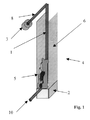
- FIG. 1 is a schematic perspective view of a heat flux measurement pipe according to the present invention in position at a fire test set up.
- FIG. 2 is a cross section of the heat-flux measurement pipe of FIG. 1 with a portion moved.
- FIG. 3 is a schematic illustration of an arrangement of temperature sensors in the heat-flux measurement pipe of FIG. 1 .
- FIG. 4 is a schematic illustration of a fire test set up employing heat flux measurement pipes according to the present invention.
- FIG. 5 is a graphical representation of the vertical and horizontal distribution of heat flux of the fire in the fire test set up of FIG. 4 .
- FIG. 6 is a sketch showing how to determine the effective heat flux and length from the measured vertical and horizontal heat flux distributions shown in FIG. 5 .
- the heat flux measurement device or heat flux measurement pipe, according to the present invention, which is designated generally by the reference numeral 1 , is designed to be installed within a testing apparatus 4 for testing the flame properties of materials.
- the heat flux measurement device 1 runs the vertical length of a testing apparatus 4 that includes a gas burner 2 and test panels 6 of material to be tested.
- Cold water enters the heat flux measurement device 1 through a water flow rate measurement device 3 and an inlet conduit 8 connected to the top of the device, and heated water exits through an outlet conduit 10 connected at the bottom of the device.
- the product of the water flow rate and the segmental increases in water temperature as water flows through the device 1 indicates the distribution of heat transfer to the device 1 from both the flames 5 being supplied by the gas burner 2 and the panels 6 of the material being tested. From this heat transfer distribution, information about the fire behavioral characteristics of the panels 6 can be obtained.
- the heat flux measurement device 1 has a core 12 that can be generally cylindrical and made out of aluminum.
- the core 12 is machined to form a spiral groove, which defines a reduced-diameter portion 20 and extends the length of the core.
- the machining leaves on core 12 a helical rib 16 that snugly engages the inside of an outer pipe 18 defining the exterior of a heat flux measurement device 1 .
- the outer pipe 18 can be made of steel.
- the reduced diameter portion 20 defines a radially inner surface of a spiral water passageway 14 .
- the inlet conduit 8 (FIG. 1) is connected to the top of the passageway 14
- the outlet conduit 10 (FIG. 1) is connected to the bottom of the passageway 14 .
- the core outer diameter is about 0.74 inches; the distance between convolutions of the rib is about 0.5 inches; the rib 16 is about 0.125 inches wide; and the distance between the inner surface of the outer pipe 18 and the reduced-diameter portion 20 of the core 12 is about 0.135 inches.
- Thermocouple lead wires 24 are shown extending out the top and bottom of the core. Portions of the lead wires 24 extending through the passageway 14 are not shown.
- thermocouples 22 a - 22 g are located at spaced positions along the spiral water passageway 14 of the core.
- a schematic of the thermocouple layout is shown in FIG. 3 .
- the thermocouple leads are threaded helically around the core 12 through the passageway 14 to the exit of the passageway at the bottom of the heat flux measurement device 1 and then to a measurement station where thermocouple differential voltages are measured.
- a thermocouple is a sensing element with two dissimilar metallic conductors joined end to end, the junction, when heated, producing a voltage differential between the two conductors.
- the temperature at the thermocouple lead can be determined from the voltage differential using standard tables.
- thermocouples 22 a - 22 g are used to measure the temperatures of the water flowing through the heat flux measurement device 1 at their respective locations.
- the product of the water flow rate and the temperature difference between adjacent thermocouples determines is the heat gain in the segment of pipe between these thermocouples. Dividing this heat gain by the surface area of the pipe between the adjacent thermocouples gives the local heat flux.
- Lead wires 24 from the thermocouples 22 a - 22 g extend upward through the passageway 14 and out at the top of the device 1 .
- a port can be formed adjacent to the inlet of the passageway 14 , through the top of the inner core 12 , with the lead wires extending through an elastomeric plug in the port in a watertight manner.
- Alternative arrangements for extending the lead wires 24 out of the device can be made.
- lead wires 24 to each of the thermocouples 22 a - 22 g extend down from the top of the heat flux measurement pipe device 1 through the spiral water passageway 14 .
- the lead wires to the various thermocouples 22 a - 22 g have different lengths so as to suspend the junctions of the thermocouples at various positions in the spiral passageway 14 , the junctions being spaced axially from one another along the axis of the heat flux measurement device 1 .
- the heat flux measurement device 1 has the seven thermocouples 22 a - 22 g spaced at distances of 0.5, 1.5, 2.5, 3.5, 5.5, 7, and 9 feet, respectively, measured from the bottom. This spacing provides greater resolution in the region of the fire.
- the thermocouples 22 a, 22 f , and 22 g are shown in FIG. 2 in exemplary positions along the spiral passageways 14 .
- the other thermocouples are not shown in FIG. 2 . Other spacing arrangements can also be useful.
- thermocouples 22 a - 22 g can be ungrounded junction chromel-alumel thermocouples.
- the ends of the lead wires 24 opposite to the junctions of the thermocouples 22 a - 22 g are connected to devices for recording the temperatures and/or calculating heat fluxes in accordance with known formulas.
- the water flow rate through the pipe is measured by an electronic flowmeter 3 (shown in FIG. 1 ), such as the +GF+Signet 8511 Micro Flow Sensor.
- This device is mounted on the water inlet 8 to the heat flux measurement device 1 as is shown in FIG. 1 .
- Leads (not shown) from the flowmeter are routed to the instrumentation station, where thermocouple signals and water flow rates are simultaneously recorded.
- the heat flux to a section of the heat flux measurement device 1 is the product of the water flow rate, the specific heat of water (expressed in units such as joules per gram degree C or BTU per pound degree F) and the difference in water temperature entering and exiting the section, respectively, divided by the exterior surface area of this section of the pipe.
- thermocouple 1 thus provide six heat flux measurements at distances along the pipe corresponding to the midpoints between pairs of adjacent thermocouples.
- the respective heat fluxes are measured simultaneously with a computer-based data acquisition system Calibration of this device requires only an initial calibration of the water flow measuring device 3 and a minor correction for differences in thermocouple offset voltages, which is easily deduced from pre-test heat flux measurements.
- the heat flux measurement device 1 has a small diameter so that it does not disturb the fire or the airflow near the fire, thus ensuring that the device itself does not alter the measurement of flame heat flux.
- the diameter of the annulus and the flow rate of water are chosen to: (1) ensure efficient heat transfer from the pipe to the water-immersed thermocouples; (2) ensure that temperature differences between thermocouples are large enough to be accurately measured, but not so large as to cause boiling before the water exits the pipe; (3) ensure that the heat flux measurement will be responsive to transient fire behavior; and (4) ensure a reasonable water pressure drop across the pipe.
- the heat flux measurement device 1 is manufactured to be a rugged instrument that is easy to install and calibrate, thus dramatically reducing the time and effort involved in installation in fire test configurations. It be easily positioned in most existing large-scale standard fire tests.
- the device 1 is water-cooled and highly durable, having no sensing elements that are exposed to flames.
- FIG. 4, FIG. 5 and FIG. 6 illustrate a measurement of both the spatial extent of heat flux from a fire and the evaluation of the total heat transfer to the test material, by using the method according to the present invention.
- a test material 31 is mounted in a wall configuration and ignited, followed by flame spread on the wall surface, 32 .
- Heat pipes 33 and 34 adjacent to the wall provide the horizontal 35 and vertical 36 distributions of the heat flux from the fire as is illustrated by FIG. 5 .
- the method of the present invention can be carried out by using linear arrays of heat-flux-gauges-instead of the heat pipes 33 and 34 .
- the area under each curve represents the integral of the heat flux with respect to distance along the horizontal 33 or vertical 34 heat pipe.
- the total heat transfer to a burning commodity is calculated by integrating in both the horizontal and vertical directions.
- the heat flux measurements also indicate the spatial extent of the fire, horizontally 35 a - 35 b, and vertically, 36 a - 36 b, from which the burning surface area is inferred.
- FIG. 6 shows how to calculate the effective heat flux, q 0 , and the effective width, l, from a measured heat flux distribution.
- the effective heat flux, q 0 , and the effective width, l, of the heat flux can be determined by first setting
- f(x) is the measured variation in heat flux with distance
- the procedure can apply to either the vertical or horizontal distributions.
- the density of water per unit material surface area, m w n , needed to absorb the heat flux, q 0 , is equal to q 0 /L, where L is the heat required to vaporize a unit mass of the sprinkler water.
- a f is the area of the exposed material per unit floor area. It is assumed here that the sprinkler water can reach most of the exposed test material surface area. In addition, it is assumed that the water is applied soon enough for it to reach the burning surface without being blown away by the rising fire plume from a fire that has grown to become very large.
- Test materials are often classified in terms of their relative fire hazard, or the sprinkler water flow rate per unit surface area required to control the fire at the moment when sprinklers might sense the fire and activate.
Landscapes
- Physics & Mathematics (AREA)
- Chemical & Material Sciences (AREA)
- General Physics & Mathematics (AREA)
- Combustion & Propulsion (AREA)
- Engineering & Computer Science (AREA)
- General Health & Medical Sciences (AREA)
- Biochemistry (AREA)
- Analytical Chemistry (AREA)
- Immunology (AREA)
- Pathology (AREA)
- Life Sciences & Earth Sciences (AREA)
- Health & Medical Sciences (AREA)
- Investigating Or Analyzing Materials Using Thermal Means (AREA)
Abstract
Description

Claims (9)
Priority Applications (6)
| Application Number | Priority Date | Filing Date | Title |
|---|---|---|---|
| US09/804,075 US6499357B2 (en) | 2001-03-13 | 2001-03-13 | Heat flux measurement pipe and method for determining sprinkler water delivery requirement |
| DE60236799T DE60236799D1 (en) | 2001-03-13 | 2002-03-12 | METHOD FOR DETERMINING SPRINKLER WATER SUPPLY REQUIREMENTS |
| PCT/US2002/007188 WO2002073168A1 (en) | 2001-03-13 | 2002-03-12 | Heat flux measurement pipe and method for determining sprinkler water delivery requirement |
| EP02713816A EP1409987B1 (en) | 2001-03-13 | 2002-03-12 | Method for determining sprinkler water delivery requirement |
| CNB028098358A CN1327199C (en) | 2001-03-13 | 2002-03-12 | Heat flux measurement pipe and method for deter mining sprinkler water delivery requirement |
| US10/292,430 US6862941B2 (en) | 2001-03-13 | 2002-11-13 | Heat flux measurement pipe and method for determining sprinkler water delivery requirement |
Applications Claiming Priority (1)
| Application Number | Priority Date | Filing Date | Title |
|---|---|---|---|
| US09/804,075 US6499357B2 (en) | 2001-03-13 | 2001-03-13 | Heat flux measurement pipe and method for determining sprinkler water delivery requirement |
Related Child Applications (1)
| Application Number | Title | Priority Date | Filing Date |
|---|---|---|---|
| US10/292,430 Division US6862941B2 (en) | 2001-03-13 | 2002-11-13 | Heat flux measurement pipe and method for determining sprinkler water delivery requirement |
Publications (2)
| Publication Number | Publication Date |
|---|---|
| US20020152818A1 US20020152818A1 (en) | 2002-10-24 |
| US6499357B2 true US6499357B2 (en) | 2002-12-31 |
Family
ID=25188131
Family Applications (2)
| Application Number | Title | Priority Date | Filing Date |
|---|---|---|---|
| US09/804,075 Expired - Lifetime US6499357B2 (en) | 2001-03-13 | 2001-03-13 | Heat flux measurement pipe and method for determining sprinkler water delivery requirement |
| US10/292,430 Expired - Fee Related US6862941B2 (en) | 2001-03-13 | 2002-11-13 | Heat flux measurement pipe and method for determining sprinkler water delivery requirement |
Family Applications After (1)
| Application Number | Title | Priority Date | Filing Date |
|---|---|---|---|
| US10/292,430 Expired - Fee Related US6862941B2 (en) | 2001-03-13 | 2002-11-13 | Heat flux measurement pipe and method for determining sprinkler water delivery requirement |
Country Status (5)
| Country | Link |
|---|---|
| US (2) | US6499357B2 (en) |
| EP (1) | EP1409987B1 (en) |
| CN (1) | CN1327199C (en) |
| DE (1) | DE60236799D1 (en) |
| WO (1) | WO2002073168A1 (en) |
Cited By (1)
| Publication number | Priority date | Publication date | Assignee | Title |
|---|---|---|---|---|
| US20050126259A1 (en) * | 2003-12-11 | 2005-06-16 | Fm Global Technologies, Llc | Characterization of mist sprays using a phase-doppler analyzer and an iso-kinetic sampling for validation of scale modeling of water mist fire suppression |
Families Citing this family (10)
| Publication number | Priority date | Publication date | Assignee | Title |
|---|---|---|---|---|
| CN100498313C (en) * | 2005-05-14 | 2009-06-10 | 富准精密工业(深圳)有限公司 | Method and apparatus for detecting heat conducting pipe performance |
| EP1948326B1 (en) * | 2005-10-21 | 2016-06-01 | Tyco Fire Products LP | Ceiling-only dry sprinkler systems and methods for addressing a storage occupancy fire |
| US20090288846A1 (en) * | 2006-07-05 | 2009-11-26 | Tyco Fire Products Lp | Dry sprinkler system and design methods |
| DE102009021600B4 (en) * | 2009-05-15 | 2015-10-01 | Chemin Gmbh | Device and method for detecting the specific heat flow |
| CN101571429B (en) * | 2009-05-27 | 2011-12-14 | 北京航空航天大学 | High temperature-pressure radiation heat flow meter |
| TW201118372A (en) * | 2009-11-25 | 2011-06-01 | Inventec Corp | Method for testing heat pipe |
| CN104698024A (en) * | 2013-12-06 | 2015-06-10 | 中国飞机强度研究所 | Thermal test method for large-structure ablative material |
| CN106290466B (en) * | 2016-08-01 | 2023-04-25 | 国网安徽省电力公司电力科学研究院 | Fire lateral spread test device between bundled cables |
| WO2019165080A1 (en) * | 2018-02-21 | 2019-08-29 | Critchley Jacob Alan Graham | Utility and appliance fire suppression system, compositions, and methods |
| CN112133462B (en) * | 2020-09-24 | 2022-07-29 | 中国核动力研究设计院 | Power calibration method for critical device |
Citations (12)
| Publication number | Priority date | Publication date | Assignee | Title |
|---|---|---|---|---|
| US2329813A (en) | 1938-11-04 | 1943-09-21 | Landis & Gyr Ag | Heat measuring method and apparatus |
| US3167957A (en) | 1959-07-14 | 1965-02-02 | Riello Filli Officine Fonderie | Heat meter |
| US3580070A (en) | 1968-07-11 | 1971-05-25 | Edward H Cumpston Jr | Heat meter |
| US3712131A (en) * | 1971-02-22 | 1973-01-23 | W Smith | Heat flux indicator |
| US4812051A (en) | 1985-05-10 | 1989-03-14 | Magyar Optikai Muvek | Apparatus for investigating thermal transformations |
| US4926356A (en) | 1988-02-29 | 1990-05-15 | The Boeing Company | Test apparatus for measuring heat release of certain materials |
| US4925314A (en) | 1987-12-17 | 1990-05-15 | Institut Francais Du Petrole | Device for detecting a thermal phenomenon occurring in a product |
| US5315292A (en) * | 1993-01-11 | 1994-05-24 | Prior Mitchell K | Ceiling mountable smoke detector and fire extinguisher combination |
| US5940784A (en) | 1996-03-08 | 1999-08-17 | Metrisa, Inc. | Heat flow meter instruments |
| US6085585A (en) * | 1999-04-19 | 2000-07-11 | Factory Mutual Research Corporation | Sprinkler performance evaluation system |
| US6121882A (en) * | 1999-01-04 | 2000-09-19 | The United States Of America As Represented By The Secretary Of The Navy | Munitions cook-off warning system |
| US6158476A (en) * | 1997-08-29 | 2000-12-12 | Trelleborg Viking As | Tune or hose capable of withstanding extreme heat flux densities |
Family Cites Families (13)
| Publication number | Priority date | Publication date | Assignee | Title |
|---|---|---|---|---|
| US3561377A (en) * | 1970-05-15 | 1971-02-09 | Howard R Amundsen | Open pit vortex incineration arrangement |
| NL8004738A (en) * | 1980-08-21 | 1980-11-28 | Kema Nv | HEAT QUANTITY METER. |
| US4519246A (en) * | 1981-12-21 | 1985-05-28 | Advanced Semiconductor Materials International, N.V. | Improved flow meter |
| JPS61104144A (en) * | 1984-10-26 | 1986-05-22 | Nippon Denso Co Ltd | Control device for engine |
| US4574643A (en) * | 1984-10-31 | 1986-03-11 | Alberta Oil Sands Technology And Research Authority | Two phase flowmeter |
| JPH0623777B2 (en) * | 1986-06-13 | 1994-03-30 | 株式会社日立製作所 | Simultaneous measurement of fluid temperature and velocity |
| NL8900474A (en) * | 1989-02-24 | 1990-09-17 | Bronkhorst High Tech Bv | MASS FLOW METER WITH TEMPERATURE SENSORS. |
| US5233868A (en) * | 1992-04-13 | 1993-08-10 | Coats Montgomery R | Non-intrusive mass flow measuring apparatus and method |
| US5622639A (en) * | 1993-07-29 | 1997-04-22 | Tokyo Electron Kabushiki Kaisha | Heat treating apparatus |
| US5598847A (en) * | 1994-12-28 | 1997-02-04 | Pacesetter, Inc. | Implantable flow sensor apparatus and method |
| GB2317014B (en) * | 1996-08-28 | 2000-06-28 | United Biscuits Ltd | Improvements in and relating to the measurement of heat flux in ovens |
| FR2780505B1 (en) * | 1998-06-26 | 2000-09-15 | Montupet Sa | THERMAL FATIGUE TEST BENCH OF COMBUSTION ENGINE CYLINDERS, AND RELATED METHODS |
| US6062069A (en) * | 1998-08-05 | 2000-05-16 | The University Of Chicago | High temperature fouling test unit |
-
2001
- 2001-03-13 US US09/804,075 patent/US6499357B2/en not_active Expired - Lifetime
-
2002
- 2002-03-12 WO PCT/US2002/007188 patent/WO2002073168A1/en not_active Ceased
- 2002-03-12 DE DE60236799T patent/DE60236799D1/en not_active Expired - Lifetime
- 2002-03-12 EP EP02713816A patent/EP1409987B1/en not_active Expired - Lifetime
- 2002-03-12 CN CNB028098358A patent/CN1327199C/en not_active Expired - Fee Related
- 2002-11-13 US US10/292,430 patent/US6862941B2/en not_active Expired - Fee Related
Patent Citations (12)
| Publication number | Priority date | Publication date | Assignee | Title |
|---|---|---|---|---|
| US2329813A (en) | 1938-11-04 | 1943-09-21 | Landis & Gyr Ag | Heat measuring method and apparatus |
| US3167957A (en) | 1959-07-14 | 1965-02-02 | Riello Filli Officine Fonderie | Heat meter |
| US3580070A (en) | 1968-07-11 | 1971-05-25 | Edward H Cumpston Jr | Heat meter |
| US3712131A (en) * | 1971-02-22 | 1973-01-23 | W Smith | Heat flux indicator |
| US4812051A (en) | 1985-05-10 | 1989-03-14 | Magyar Optikai Muvek | Apparatus for investigating thermal transformations |
| US4925314A (en) | 1987-12-17 | 1990-05-15 | Institut Francais Du Petrole | Device for detecting a thermal phenomenon occurring in a product |
| US4926356A (en) | 1988-02-29 | 1990-05-15 | The Boeing Company | Test apparatus for measuring heat release of certain materials |
| US5315292A (en) * | 1993-01-11 | 1994-05-24 | Prior Mitchell K | Ceiling mountable smoke detector and fire extinguisher combination |
| US5940784A (en) | 1996-03-08 | 1999-08-17 | Metrisa, Inc. | Heat flow meter instruments |
| US6158476A (en) * | 1997-08-29 | 2000-12-12 | Trelleborg Viking As | Tune or hose capable of withstanding extreme heat flux densities |
| US6121882A (en) * | 1999-01-04 | 2000-09-19 | The United States Of America As Represented By The Secretary Of The Navy | Munitions cook-off warning system |
| US6085585A (en) * | 1999-04-19 | 2000-07-11 | Factory Mutual Research Corporation | Sprinkler performance evaluation system |
Cited By (2)
| Publication number | Priority date | Publication date | Assignee | Title |
|---|---|---|---|---|
| US20050126259A1 (en) * | 2003-12-11 | 2005-06-16 | Fm Global Technologies, Llc | Characterization of mist sprays using a phase-doppler analyzer and an iso-kinetic sampling for validation of scale modeling of water mist fire suppression |
| US7181952B2 (en) | 2003-12-11 | 2007-02-27 | Fm Global Technologies, Llc | Characterization of mist sprays using a phase-doppler particle analyzer and an iso-kinetic sampling probe |
Also Published As
| Publication number | Publication date |
|---|---|
| CN1327199C (en) | 2007-07-18 |
| US6862941B2 (en) | 2005-03-08 |
| US20030070493A1 (en) | 2003-04-17 |
| EP1409987A4 (en) | 2006-11-08 |
| EP1409987B1 (en) | 2010-06-23 |
| CN1509407A (en) | 2004-06-30 |
| WO2002073168A1 (en) | 2002-09-19 |
| US20020152818A1 (en) | 2002-10-24 |
| DE60236799D1 (en) | 2010-08-05 |
| EP1409987A1 (en) | 2004-04-21 |
Similar Documents
| Publication | Publication Date | Title |
|---|---|---|
| US6499357B2 (en) | Heat flux measurement pipe and method for determining sprinkler water delivery requirement | |
| US10634536B2 (en) | Method and system for multi-phase flow measurement | |
| US5067094A (en) | Quantifying isolation valve leakage | |
| US9746434B2 (en) | Method and system for determining flow distribution through a component | |
| US9880035B2 (en) | Method and system for detecting coking growth and maldistribution in refinery equipment | |
| Andersson et al. | Experimental methods of estimating heat transfer in circulating fluidized bed boilers | |
| US9500554B2 (en) | Method and system for detecting a leak in a pipeline | |
| US9778115B2 (en) | Method and system for detecting deposits in a vessel | |
| Farzaneh-Gord et al. | Potential use of capillary tube thermal mass flow meters to measure residential natural gas consumption | |
| Junkhan et al. | Investigation of turbulators for fire tube boilers | |
| Khodsiani et al. | Spatially resolved investigation of flame particle interaction in a two dimensional model packed bed | |
| CN101915781B (en) | Thermal contact resistance test equipment with compensating heating device | |
| Bryant et al. | Improving the state-of-the-art in flow measurements for large-scale oxygen consumption calorimetry | |
| Baukal Jr | Heat transfer from flame impingement normal to a plane surface | |
| Diller et al. | Heat flux measurements | |
| JPH03107735A (en) | Maximum temperature evaluating device for power cable buried underground | |
| Kulkarni | Radiative and total heat feedback from flames to surface in vertical wall fires | |
| EP0466825A1 (en) | Quantifying isolation valve leakage | |
| Gosmeyer | An experimental study of heat transfer in a large particle heated fluidized bed | |
| ES2394592B1 (en) | SYSTEM AND PROCEDURE FOR MEASURING THE MAXIMUM RATE OF HEAT ISSUED BY A DYNAMIC FIRE FRONT. | |
| Koski et al. | Design of an actively cooled plate calorimeter for the investigation of pool fire heat fluxes | |
| Han et al. | LIMITATIONS OF SPHERE ANEMOMETRY FOR LOW GAS VELOCITY MEASUREMENTS | |
| Huff | Variation of convective heat-transfer coefficient around a simulated rocket cooling tube section | |
| Chance | An experimental investigation of heat transfer and friction in a circular tube for laminar flow of air under conditions of large transverse temperature gradients | |
| Bansal | Heat transfer studies from single cylinder and tube bundle in fluidized bed |
Legal Events
| Date | Code | Title | Description |
|---|---|---|---|
| AS | Assignment |
Owner name: FACTORY MUTUAL RESEARCH CORPORATION, RHODE ISLAND Free format text: ASSIGNMENT OF ASSIGNORS INTEREST;ASSIGNORS:ALPERT, RONALD L.;DE RIS, JOHN L.;ORLOFF, LAWRENCE;REEL/FRAME:011838/0482 Effective date: 20010502 |
|
| AS | Assignment |
Owner name: FM GLOBAL TECHNOLOGIES, LLC, RHODE ISLAND Free format text: ASSIGNMENT OF ASSIGNORS INTEREST;ASSIGNOR:FACTORY MUTUAL RESEARCH CORPORATION;REEL/FRAME:012795/0367 Effective date: 20020318 |
|
| STCF | Information on status: patent grant |
Free format text: PATENTED CASE |
|
| FPAY | Fee payment |
Year of fee payment: 4 |
|
| FPAY | Fee payment |
Year of fee payment: 8 |
|
| FEPP | Fee payment procedure |
Free format text: PAYOR NUMBER ASSIGNED (ORIGINAL EVENT CODE: ASPN); ENTITY STATUS OF PATENT OWNER: LARGE ENTITY |
|
| FPAY | Fee payment |
Year of fee payment: 12 |
|
| AS | Assignment |
Owner name: FACTORY MUTUAL INSURANCE COMPANY, RHODE ISLAND Free format text: CONFIRMATORY ASSIGNMENT OF PATENTS;ASSIGNOR:FM GLOBAL TECHNOLOGIES LLC;REEL/FRAME:037957/0956 Effective date: 20060101 |
|
| AS | Assignment |
Owner name: FACTORY MUTUAL INSURANCE COMPANY, RHODE ISLAND Free format text: CORRECTIVE ASSIGNMENT TO CORRECT THE INCORRECT PATENT 6449357 PREVIOUSLY RECORDED AT REEL: 037957 FRAME: 0956. ASSIGNOR(S) HEREBY CONFIRMS THE CONFIRMATORY ASSIGNMENT;ASSIGNOR:FM GLOBAL TECHNOLOGIES LLC;REEL/FRAME:038364/0476 Effective date: 20060101 |