US6496138B1 - Electromagnetic wave radar device mounted on a car - Google Patents
Electromagnetic wave radar device mounted on a car Download PDFInfo
- Publication number
- US6496138B1 US6496138B1 US09/095,650 US9565098A US6496138B1 US 6496138 B1 US6496138 B1 US 6496138B1 US 9565098 A US9565098 A US 9565098A US 6496138 B1 US6496138 B1 US 6496138B1
- Authority
- US
- United States
- Prior art keywords
- bumper
- electromagnetic wave
- wave radar
- radar device
- device mounted
- Prior art date
- Legal status (The legal status is an assumption and is not a legal conclusion. Google has not performed a legal analysis and makes no representation as to the accuracy of the status listed.)
- Expired - Lifetime
Links
Images


Classifications
-
- H—ELECTRICITY
- H01—ELECTRIC ELEMENTS
- H01Q—ANTENNAS, i.e. RADIO AERIALS
- H01Q1/00—Details of, or arrangements associated with, antennas
- H01Q1/27—Adaptation for use in or on movable bodies
- H01Q1/32—Adaptation for use in or on road or rail vehicles
- H01Q1/325—Adaptation for use in or on road or rail vehicles characterised by the location of the antenna on the vehicle
- H01Q1/3283—Adaptation for use in or on road or rail vehicles characterised by the location of the antenna on the vehicle side-mounted antennas, e.g. bumper-mounted, door-mounted
-
- G—PHYSICS
- G01—MEASURING; TESTING
- G01S—RADIO DIRECTION-FINDING; RADIO NAVIGATION; DETERMINING DISTANCE OR VELOCITY BY USE OF RADIO WAVES; LOCATING OR PRESENCE-DETECTING BY USE OF THE REFLECTION OR RERADIATION OF RADIO WAVES; ANALOGOUS ARRANGEMENTS USING OTHER WAVES
- G01S13/00—Systems using the reflection or reradiation of radio waves, e.g. radar systems; Analogous systems using reflection or reradiation of waves whose nature or wavelength is irrelevant or unspecified
- G01S13/88—Radar or analogous systems specially adapted for specific applications
- G01S13/93—Radar or analogous systems specially adapted for specific applications for anti-collision purposes
- G01S13/931—Radar or analogous systems specially adapted for specific applications for anti-collision purposes of land vehicles
-
- H—ELECTRICITY
- H01—ELECTRIC ELEMENTS
- H01Q—ANTENNAS, i.e. RADIO AERIALS
- H01Q1/00—Details of, or arrangements associated with, antennas
- H01Q1/27—Adaptation for use in or on movable bodies
- H01Q1/32—Adaptation for use in or on road or rail vehicles
- H01Q1/3208—Adaptation for use in or on road or rail vehicles characterised by the application wherein the antenna is used
- H01Q1/3233—Adaptation for use in or on road or rail vehicles characterised by the application wherein the antenna is used particular used as part of a sensor or in a security system, e.g. for automotive radar, navigation systems
-
- H—ELECTRICITY
- H01—ELECTRIC ELEMENTS
- H01Q—ANTENNAS, i.e. RADIO AERIALS
- H01Q1/00—Details of, or arrangements associated with, antennas
- H01Q1/42—Housings not intimately mechanically associated with radiating elements, e.g. radome
-
- H—ELECTRICITY
- H01—ELECTRIC ELEMENTS
- H01Q—ANTENNAS, i.e. RADIO AERIALS
- H01Q15/00—Devices for reflection, refraction, diffraction or polarisation of waves radiated from an antenna, e.g. quasi-optical devices
- H01Q15/02—Refracting or diffracting devices, e.g. lens, prism
- H01Q15/08—Refracting or diffracting devices, e.g. lens, prism formed of solid dielectric material
-
- H—ELECTRICITY
- H01—ELECTRIC ELEMENTS
- H01Q—ANTENNAS, i.e. RADIO AERIALS
- H01Q19/00—Combinations of primary active antenna elements and units with secondary devices, e.g. with quasi-optical devices, for giving the antenna a desired directional characteristic
- H01Q19/06—Combinations of primary active antenna elements and units with secondary devices, e.g. with quasi-optical devices, for giving the antenna a desired directional characteristic using refracting or diffracting devices, e.g. lens
- H01Q19/08—Combinations of primary active antenna elements and units with secondary devices, e.g. with quasi-optical devices, for giving the antenna a desired directional characteristic using refracting or diffracting devices, e.g. lens for modifying the radiation pattern of a radiating horn in which it is located
-
- G—PHYSICS
- G01—MEASURING; TESTING
- G01S—RADIO DIRECTION-FINDING; RADIO NAVIGATION; DETERMINING DISTANCE OR VELOCITY BY USE OF RADIO WAVES; LOCATING OR PRESENCE-DETECTING BY USE OF THE REFLECTION OR RERADIATION OF RADIO WAVES; ANALOGOUS ARRANGEMENTS USING OTHER WAVES
- G01S13/00—Systems using the reflection or reradiation of radio waves, e.g. radar systems; Analogous systems using reflection or reradiation of waves whose nature or wavelength is irrelevant or unspecified
- G01S13/88—Radar or analogous systems specially adapted for specific applications
- G01S13/93—Radar or analogous systems specially adapted for specific applications for anti-collision purposes
- G01S13/931—Radar or analogous systems specially adapted for specific applications for anti-collision purposes of land vehicles
- G01S2013/9327—Sensor installation details
- G01S2013/93271—Sensor installation details in the front of the vehicles
-
- G—PHYSICS
- G01—MEASURING; TESTING
- G01S—RADIO DIRECTION-FINDING; RADIO NAVIGATION; DETERMINING DISTANCE OR VELOCITY BY USE OF RADIO WAVES; LOCATING OR PRESENCE-DETECTING BY USE OF THE REFLECTION OR RERADIATION OF RADIO WAVES; ANALOGOUS ARRANGEMENTS USING OTHER WAVES
- G01S13/00—Systems using the reflection or reradiation of radio waves, e.g. radar systems; Analogous systems using reflection or reradiation of waves whose nature or wavelength is irrelevant or unspecified
- G01S13/88—Radar or analogous systems specially adapted for specific applications
- G01S13/93—Radar or analogous systems specially adapted for specific applications for anti-collision purposes
- G01S13/931—Radar or analogous systems specially adapted for specific applications for anti-collision purposes of land vehicles
- G01S2013/9327—Sensor installation details
- G01S2013/93275—Sensor installation details in the bumper area
Definitions
- the present invention relates to an electromagnetic wave radar device mounted on a car, which helps improve external appearance of a car without impairing radar function, and is fabricated using a decreased number of parts at a reduced cost.
- An electromagnetic wave radar device has heretofore been used as an obstacle sensor being mounted on a car.
- the device of this kind has been disclosed in, for example, “Antenna for Microwaves/Millimeter Waves and Peripheral Technology”, Nov. 21, 1993, issued by Mimatsu Data System, pp. 474-477, “Symposium on Utilizing Electromagnetic Waves, Preliminary Papers on Promoting the Utilization of Quasi-Microwaves/millimeter waves”, June, 1990, issued by, Foundation, Electromagnetic Wave System Development Center, p. 111), and “Handbook of Antenna Engineering”, Oct. 30, 1980, edited by the Academy of Electronic Data Communication, issued by Ohm Co., pp. 359-361.
- FIG. 17 is a perspective view showing the appearance of a conventional electromagnetic wave radar device mounted on a car disclosed in the above-mentioned literature “Antenna for Microwaves/Millimeter Waves and Peripheral Technology”, p. 477.
- an electromagnetic wave radar body 1 mounted on a car is provided on an upper part of a bumper 3 of a vehicle 2 and is disposed at a central part of a front grille 4 .
- the electromagnetic wave radar body 1 is directly disposed on a front part of the vehicle 2 , or is disposed in an opening formed in the front grille 4 , emits electromagnetic waves of a predetermined frequency as a transmission beam W 1 toward the front of the vehicle 2 , and receives the electromagnetic waves reflected by an obstacle (not shown) as a reception beam W 2 .
- a transmission/reception antenna in the electromagnetic wave radar body 1 is located on the travelling side of the vehicle 2 , and is covered by a known radome (not shown) made of a material which permits the electromagnetic waves to pass through in order to prevent the antenna from the external damaging factors such as rain, dust and dirt and to prevent its performance from being deteriorated.
- an opening (not shown) is formed in the bumper 3 , and the electromagnetic wave radar body 1 is disposed in the opening.
- an opening wider than an area corresponding to the transmission/reception antenna is formed in the bumper 3 or in the front grille 4 in order to mount the electromagnetic radar body 1 on the car 2 .
- the pattern of the transmission/reception electromagnetic waves is affected by the front grille 4 irrespective of the material (metal or dielectric) of the front grille 4 , causing the object-detecting performance of the electromagnetic radar body 1 to be greatly deteriorated.
- the opening must be formed in the bumper 3 or in the grille 4 for installing the electromagnetic wave radar body 1 , leaving a problem of impairing the appearance of the car 2 .
- the electromagnetic wave radar body 1 When the electromagnetic wave radar body 1 is installed on a portion of the front grille 4 , furthermore, the radar function is impaired being affected by the grille member.
- a separate radome must be provided to protect the electromagnetic wave radar body 1 from the external environment, resulting in an increase in the number of parts and in an increase in the cost.
- the present invention is directed to an electromagnetic wave radar device mounted on a car at a reduced cost, by using the bumper as a radome portion deteriorating neither the radar function nor the appearance of the car, and using a decreased number of parts by giving attention to the fact that the bumper of a car is made of a dielectric.
- An electromagnetic wave radar device mounted on a car comprises an electromagnetic wave radar body mounted on a car and for transmitting and receiving electromagnetic waves of a predetermined frequency, and a radome portion made of a material which permits the electromagnetic waves to transmit through and covers the electromagnetic radar body, the electromagnetic wave radar body being disposed on the back surface side of the bumper of the car, and the radome portion being formed by a portion of the bumper of the car.
- the radome portion in the bumper has a dielectric lens portion for focusing the electromagnetic waves.
- the dielectric lens portion is constituted by a thick portion that is formed in the bumper integrally together.
- the dielectric lens portion is secured to a portion on the back surface of the bumper and is constituted integrally with the bumper.
- the dielectric lens portion is inserted in the opening of the bumper and is constituted integrally with the bumper.
- the radome portion in the bumper has a polarizer unit for transforming linear polarization and circular polarization relative to each other, and the polarizer unit has corrugated grooves.
- a depth d of the corrugated grooves is set to a value that satisfies the following formula
- the polarizer unit is formed in the bumper integrally together.
- the polarizer unit is secured to a portion on the back surface of the bumper and is constituted integrally with the bumper.
- the polarizer unit is inserted in the opening in the bumper and is constituted integrally with the bumper.
- the radome portion in the bumper is coated with a coating material in a predetermined thickness, the coating material being composed of a material which permits the electromagnetic waves to transmit through.
- the coating material is applied onto at least either the front surface or the back surface of the radome portion of the bumper and, when a relative permittivity of the bumper is denoted by ⁇ c, a relative permittivity es of the coating material is set to a value that satisfies the following formula,
- a thickness ts of the coating material is set to a value that satisfies the following formula
- the radome portion in the bumper has a central portion which is directly related to transmitting and receiving the electromagnetic waves, and a peripheral portion surrounding the central portion, the peripheral portion being coated with an radiowave absorber on the side of the back surface thereof that faces the electromagnetic wave radar body.
- FIG. 1 is a side view illustrating an apparatus according to an embodiment 1 of the present invention
- FIG. 2 is a perspective view illustrating, on an enlarged scale, a major portion according to the embodiment 1 of the present invention
- FIG. 3 is a perspective view illustrating a major portion according to an embodiment 3 of the present invention.
- FIG. 4 is a side sectional view along the line A—A in FIG. 7;
- FIG. 5 is a perspective view illustrating a major portion according to an embodiment 4 of the present invention.
- FIG. 6 is a side sectional view along the line B—B in FIG. 7;
- FIG. 7 is a perspective view illustrating a major portion according to an embodiment 5 of the present invention.
- FIG. 8 is a side sectional view along the line C—C in FIG. 7;
- FIG. 9 is a perspective view illustrating a major portion according to an embodiment 6 of the present invention.
- FIG. 10 is a side sectional view along the line D—D in FIG. 9;
- FIG. 11 is a perspective view illustrating, on an enlarged scale, a polarizer unit in FIG. 10;
- FIG. 12 is a side sectional view illustrating a major portion according to an embodiment 7 of the present invention.
- FIG. 13 is a side sectional view illustrating a major portion according to an embodiment 8 of the present invention.
- FIG. 14 is a side sectional view illustrating a major portion according to an embodiment 9 of the present invention.
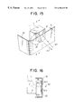
- FIG. 15 is a perspective view illustrating a major portion according to an embodiment 10 of the present invention.
- FIG. 16 is a side sectional view along the line E—E in FIG. 15;
- FIG. 17 is a perspective view illustrating the appearance of a conventional electromagnetic wave radar device mounted on a car.
- FIG. 1 is a side view illustrating the appearance of the embodiment 1 of the present invention
- FIG. 2 is a perspective view illustrating, on an enlarged scale, a major portion in FIG. 1 .
- an electromagnetic wave radar body 1 is disposed on the side of the back surface 30 A of a bumper 30 , part of the bumper 30 serving as a radome portion of the electromagnetic wave radar body 1 .
- the electromagnetic radar body 1 has an antenna 11 for transmission and an antenna 12 for reception, but may have a single antenna for transmission and reception.
- the radome portion working at least as a radome is made of a dielectric which permits the electromagnetic waves to transmit through.
- the formula (1) can be derived from, for example, the content described on page 2 of “Radome” (Technical Report of Mitsubishi Denki Co., Vol. 29, No. 7 (July), by Takashi Kitsuregawa), p. 2.
- the radome portion of the bumper 30 works as a radome of a half wavelength exhibiting transmission characteristics of a very low loss for the electromagnetic waves that are used.
- electromagnetic wave radar body 1 may be disposed behind the back surface 30 A of the bumper 30 , offering an increased degree of freedom for designing the appearance of the car 2 .
- the type of the antennas 11 and 12 can be freely selected without any limitation from the standpoint of design.
- the dielectric layer is only that of the bumper 30 , and the transmission characteristics of the electromagnetic waves can be improved.
- the thickness tc of the radome portion of the bumper 30 is set to an optimum value depending upon a predetermined frequency f.
- the thickness tc of the bumper 30 may be arbitrarily selected.
- the radome portion of the bumper 30 is formed maintaining a predetermined thickness tc to accomplish good electromagnetic wave transmission characteristics. It is, however, also allowable to add other effective functions to the radome portion of the bumper 30 .
- FIG. 3 is a perspective view illustrating a major portion of an embodiment 3 of the present invention in which a focusing lens function is added to the radome portion of the bumper 30
- FIG. 4 is a side sectional view along the line A—A in FIG. 3 .
- a dielectric lens portion 31 for focusing the electromagnetic waves is formed in the radome portion of the bumper 30 .
- the dielectric lens portion 31 is constituted by a thick portion integrally formed on the bumper 30 .
- the transmission beam W 1 transmitted from the transmission antenna 11 is focused to become highly directive. Therefore, the electromagnetic wave radar body 1 exhibits markedly improved target-detecting performance.
- the radiation characteristics of the transmission beam W 1 can be freely controlled.
- the dielectric lens portion 31 is formed integrally with the bumper 30 by molding the resin at the time of producing the bumper 30 . Therefore, the lens function is easily added to the radome portion of the bumper 30 without increasing the number of steps of production or without increasing the cost.
- the dielectric lens portion 31 is provided for the side of the transmission antenna 11 only. It is, however, also allowable to provide a dielectric lens portion (not shown) for the side of the reception antenna 12 , too, in order to focus the reception beam W 2 , too.
- the same dielectric lens portion can be formed even in the case of the transmission/reception antenna of an integral form in which the transmission antenna 11 further works as the reception antenna 12 .
- the thickness tc of the radome portion of the bumper 30 through which the electromagnetic waves transmit is changed as shown in FIG. 4, and the dielectric lens portion 31 having the shape of a convex lens in cross section is formed to accomplish the lens function. It is, however, also allowable to substantially accomplish the lens function by partly changing the relative permittivity of the dielectric lens portion 31 instead of changing the sectional shape.
- the dielectric lens portion 31 is formed by molding the resin integrally with the bumper 30 .
- a separately formed dielectric lens portion may be attached to the radome portion of the bumper 30 .
- FIG. 5 is a perspective view illustrating a major portion of an embodiment 4 of the present invention in which a separately formed dielectric lens portion is attached to the bumper 30
- FIG. 6 is a side sectional view along the line B—B in FIG. 5 .
- the dielectric lens portion 31 A is attached to the radome portion of the bumper 30 to accomplish the same lens function as the one described above.
- the position for attaching the dielectric lens portion 31 A can be adjusted depending upon the position of the antenna 11 or 12 at the time of assembling the dielectric lens portion 31 A, and the material of the dielectric lens portion 31 A can be freely selected irrespective of the material of the bumper 30 .
- the dielectric lens portion 31 A is attached to the bumper 30 to accomplish the lens function. It is, however, also allowable to form an opening in the radome portion of the bumper 30 , and insert a separate dielectric lens portion in the opening and attach it integrally together.
- FIG. 7 is a perspective view illustrating a major portion of an embodiment 5 of the present invention in which a separate dielectric lens portion is inserted in a portion of the bumper 30
- FIG. 8 is a side sectional view along the line C—C in FIG. 7 .
- an opening 30 B is formed in the radome portion of the bumper 30 , and a separate dielectric lens portion 31 B is inserted in the opening 30 B.
- the dielectric lens portion 31 B is attached to the bumper 30 integrally together through the opening 30 B to accomplish the same lens function as the one described above.
- the material of the dielectric lens portion 31 B can be freely selected irrespective of the material of the bumper 30 .
- the lens function is accomplished by the dielectric lens portion 31 B alone without at all affected by the material of the bumper 30 , making it possible to highly precisely adjust the characteristics for focusing the electromagnetic waves (transmission beam W 1 or reception beam W 2 ) that transmit through.
- the dielectric lens portion 31 B is in flush with the outer surface of the bumper 30 .
- the dielectric lens portion 31 B is not perceived from the outer side and does not deteriorate the appearance.
- the lens function is added to the radome portion of the bumper 30 . It is, however, also allowable to add a further function such as polarization transforming function.
- FIG. 9 is a perspective view illustrating a major portion of an embodiment 6 of the present invention in which the polarization transforming function is added to a portion of the bumper 30
- FIG. 10 is a side sectional view along the line D—D in FIG. 9 .
- a polarizer unit 32 is formed in the radome portion of the bumper 30 to transform linear polarization and circular polarization relative to each other, the polarizer unit 32 having a plurality of corrugated grooves 33 arranged in parallel.
- FIG. 11 is a perspective view illustrating, on an enlarged scale, the polarizer unit 32 and the corrugated grooves 33 in FIG. 10 .
- the depth d of the corrugated grooves 33 in the polarizer unit 32 is set to a value which satisfies, for example, the following formula (4),
- ⁇ m denotes a phase constant in a medium
- ⁇ o denotes a phase constant in free space
- ⁇ o is expressed by the following formula (5) by using the above-mentioned wavelength ⁇ o in free space
- the polarizer unit 32 is formed by molding a resin integrally with the bumper 30 .
- the polarizer unit 32 constituted by corrugated grooves 33 in a portion of the bumper 30 through which the electromagnetic waves (transmission beam W 1 or reception beam W 2 ) transmit through as described above, it is made possible to easily add the polarization transforming function to the radome portion of the bumper 30 in order to transform linear polarization and circular polarization relative to each other.
- the polarizer unit 32 constituted by the corrugated grooves 33 , however, it is allowed to easily impart the circular polarization and to expand the function and use of the electromagnetic wave radar device.
- the polarizer unit 32 is formed by molding the resin integrally with the bumper 30 . It is, however, also possible to attach a separate polarizer unit to the radome portion of the bumper 30 .
- FIG. 12 is a side sectional view illustrating a major portion of the embodiment 7 of the invention in which a separate polarizer unit is attached to the bumper 30 , and wherein the same portions as those described above (see FIG. 10) are denoted by the same reference numerals but their description is not repeated.
- the polarizer unit 32 A is attached to the radome portion of the bumper 30 thereby to add the same polarization transforming function as the one described above.
- the position for attaching the polarizer unit 32 A can be adjusted depending upon the position of the antenna 11 at the time of assembling the polarizer unit 32 A, and the material of the polarizer unit 32 A can be freely selected irrespective of the material of the bumper 30 .
- the polarizer unit 32 A is attached to the bumper 30 . It is, however, also allowable to form an opening 30 B in the radome portion of the bumper 30 , insert a separate polarizer unit in the opening 30 B and to attach it integrally together.
- FIG. 13 is a side sectional view illustrating a major portion of an embodiment 8 of the invention in which the separate polarizer unit is inserted in a portion of the bumper 30 , and wherein the same portions as those mentioned above (see FIG. 12) are denoted by the same reference numerals but their description is not repeated.
- an opening 30 B is formed in the radome portion of the bumper 30 , and a separate polarizer unit 32 B is inserted in the opening 30 B.
- the polarizer unit 32 B is attached to the bumper 30 integrally together through the opening 30 B to accomplish the same polarization transforming function as the one described above.
- the material of the polarizer unit 32 B can be freely selected irrespective of the material of the bumper 30 .
- the polarizer unit 32 B is formed quite irrespective of the material of the bumper 30 , the polarization characteristics for the transmitted electromagnetic waves can be highly precisely adjusted.
- the polarizer unit 32 B is forming a plane in flush with the outer surface of the bumper 30 . Upon applying any coating material on the outer side of the bumper 30 , therefore, the polarizer unit 32 B is not perceived from the outer side, and the appearance is not deteriorated.
- the thickness tc of the bumper 30 is suitably selected to improve the electromagnetic wave transmission characteristics. It is, however, also allowable to apply a non-reflection coating onto the bumper 30 in order to improve the electromagnetic wave transmission characteristics.
- FIG. 14 is a side sectional view illustrating a major portion of an embodiment 9 of the present invention in which the non-reflection coating is applied onto the bumper 30 , and wherein the same portions as those described above (see FIG. 2) are denoted by the same reference numerals but their description is not repeated.
- a coating material 34 that permits the electromagnetic waves to transmit through is applied to at least the radome portion of the bumper 30 maintaining a predetermined thickness ts, in order to impart the action of the non-reflecting coating for the electromagnetic waves that transmit through the bumper 30 .
- the coating material 34 is applied onto both the front surface and the back surface of the bumper 30 , it may be applied to at least either the front surface or the back surface of the bumper 30 .
- the relative permittivity ⁇ s of the coating material 34 is set to a value that satisfies the following formula (6),
- the thickness ts of the coating material 34 is set to a value which satisfies, for example, the following formula (7),
- the formula (7) is derived from, for example, thecontent disclosed in “Radome”, Technical Report of Mitsubishi Denki Co., Vol. 29, No. 7 (July), by Takashi Kitsuregawa, p. 5.
- the relative permittivity ⁇ s of the coating material 34 on the bumper 30 and the thickness ts are suitably selected depending upon the relative permittivity ⁇ c of the bumper 30 , thickness ts thereof, and predetermined frequency f of the electromagnetic waves that are used, so that the coating material 34 works as a non-reflecting coating for the electromagnetic waves.
- a radome of a sandwich type of a one-fourth wavelength is constituted to improve transmission characteristics of the electromagnetic waves falling perpendicularly on the radome portion.
- FIG. 15 is a perspective view illustrating a major portion of an embodiment 10 of the invention in which the radiowave absorber is applied onto the back surface 30 A of the bumper 30
- FIG. 16 is a side sectional view along the line E—E in FIG. 9 .
- the bumper 30 includes a central portion 30 C of the radome portion which is directly related to transmitting and receiving electromagnetic waves, and a peripheral portion 30 D surrounding the central portion 30 C.
- the radiowave absorber 35 is applied onto the side of the back surface 30 A of the peripheral portion 30 D, i.e., onto the side facing the antenna 11 (or antenna 12 ) of the electromagnetic wave radar body 1 .
- a coating material comprising an radiowave absorbing material is used as the radiowave absorber 35 .
- the radiowave absorber 35 is applied to the back surface 30 A of the peripheral portion 30 D in order to decrease undesired interference waves such as noise due to the transmission beam W 1 reflected by the back surface 30 A of the bumper 30 and noise from the external side.
- the electromagnetic wave radar body 1 receives the beam W 2 maintaining a high SN ratio to detect the target.
- the peripheral portion 30 D of the bumper 30 does not directly take part in the transmission and reception of the electromagnetic waves. Therefore, the function for transmitting and receiving the electromagnetic waves is not at all impaired despite the radiowave absorber 35 is applied to the back surface 30 A of the peripheral portion 30 D.
- the radiowave absorber 35 can be easily applied onto the bumper 30 through a step of coating in order to easily accomplish the function for suppressing the radiation of undesired electromagnetic waves and the function for suppressing the electromagnetic interference.
Landscapes
- Engineering & Computer Science (AREA)
- Remote Sensing (AREA)
- Radar, Positioning & Navigation (AREA)
- Physics & Mathematics (AREA)
- Computer Security & Cryptography (AREA)
- Electromagnetism (AREA)
- Computer Networks & Wireless Communication (AREA)
- General Physics & Mathematics (AREA)
- Radar Systems Or Details Thereof (AREA)
- Details Of Aerials (AREA)
- Aerials With Secondary Devices (AREA)
- Support Of Aerials (AREA)
Abstract
An electromagnetic wave radar device mounted on a car, which helps improve external appearance of a car without impairing radar function, and is fabricated using a decreased number of parts at a reduced cost. The electromagnetic wave radar device comprises an electromagnetic wave radar body 1 mounted on a car 2 and for transmitting and receiving electromagnetic waves of a predetermined frequency, and a radome portion made of a material which permits the electromagnetic waves to transmit through and covers the electromagnetic radar body, the electromagnetic wave radar body being disposed on the side of the back surface 30A of the bumper 30 of the car, and the radome portion being formed by a portion of the bumper of the car.
Description
1. Field of the Invention
The present invention relates to an electromagnetic wave radar device mounted on a car, which helps improve external appearance of a car without impairing radar function, and is fabricated using a decreased number of parts at a reduced cost.
2. Prior Art
An electromagnetic wave radar device has heretofore been used as an obstacle sensor being mounted on a car.
The device of this kind has been disclosed in, for example, “Antenna for Microwaves/Millimeter Waves and Peripheral Technology”, Nov. 21, 1993, issued by Mimatsu Data System, pp. 474-477, “Symposium on Utilizing Electromagnetic Waves, Preliminary Papers on Promoting the Utilization of Quasi-Microwaves/millimeter waves”, June, 1990, issued by, Foundation, Electromagnetic Wave System Development Center, p. 111), and “Handbook of Antenna Engineering”, Oct. 30, 1980, edited by the Academy of Electronic Data Communication, issued by Ohm Co., pp. 359-361.
FIG. 17 is a perspective view showing the appearance of a conventional electromagnetic wave radar device mounted on a car disclosed in the above-mentioned literature “Antenna for Microwaves/Millimeter Waves and Peripheral Technology”, p. 477.
In FIG. 17, an electromagnetic wave radar body 1 mounted on a car is provided on an upper part of a bumper 3 of a vehicle 2 and is disposed at a central part of a front grille 4.
The electromagnetic wave radar body 1 is directly disposed on a front part of the vehicle 2, or is disposed in an opening formed in the front grille 4, emits electromagnetic waves of a predetermined frequency as a transmission beam W1 toward the front of the vehicle 2, and receives the electromagnetic waves reflected by an obstacle (not shown) as a reception beam W2.
A transmission/reception antenna in the electromagnetic wave radar body 1 is located on the travelling side of the vehicle 2, and is covered by a known radome (not shown) made of a material which permits the electromagnetic waves to pass through in order to prevent the antenna from the external damaging factors such as rain, dust and dirt and to prevent its performance from being deteriorated.
According to the device disclosed in the above-mentioned literature “Handbook of Antenna Engineering”, an opening (not shown) is formed in the bumper 3, and the electromagnetic wave radar body 1 is disposed in the opening.
According to the conventional electromagnetic wave radar devices mounted on the car as described above, an opening wider than an area corresponding to the transmission/reception antenna is formed in the bumper 3 or in the front grille 4 in order to mount the electromagnetic radar body 1 on the car 2.
However, forming an opening in the bumper 3 or in the grille 4 imposes a limitation on designing the appearance of the car 2.
Moreover, despite the electromagnetic wave radar body 1 is disposed at the back of the opening in the front grille 4 so will not to deteriorate the appearance of the car 2, the pattern of the transmission/reception electromagnetic waves is affected by the front grille 4 irrespective of the material (metal or dielectric) of the front grille 4, causing the object-detecting performance of the electromagnetic radar body 1 to be greatly deteriorated.
In order to accomplish both the electric performance of the electromagnetic wave radar body 1 and the designing of appearance of the car 2, therefore, limitation is imposed on a place for installing the electromagnetic wave radar device 1.
In either device disclosed in the above-mentioned literatures, furthermore, a separate radome is necessary for protecting the electromagnetic wave radar body 1.
In the conventional electromagnetic wave radar devices mounted on the vehicles as described above, the opening must be formed in the bumper 3 or in the grille 4 for installing the electromagnetic wave radar body 1, leaving a problem of impairing the appearance of the car 2.
When the electromagnetic wave radar body 1 is installed on a portion of the front grille 4, furthermore, the radar function is impaired being affected by the grille member.
Besides, a separate radome must be provided to protect the electromagnetic wave radar body 1 from the external environment, resulting in an increase in the number of parts and in an increase in the cost.
The present invention is directed to an electromagnetic wave radar device mounted on a car at a reduced cost, by using the bumper as a radome portion deteriorating neither the radar function nor the appearance of the car, and using a decreased number of parts by giving attention to the fact that the bumper of a car is made of a dielectric.
An electromagnetic wave radar device mounted on a car according to the present invention comprises an electromagnetic wave radar body mounted on a car and for transmitting and receiving electromagnetic waves of a predetermined frequency, and a radome portion made of a material which permits the electromagnetic waves to transmit through and covers the electromagnetic radar body, the electromagnetic wave radar body being disposed on the back surface side of the bumper of the car, and the radome portion being formed by a portion of the bumper of the car.
In the electromagnetic wave radar device mounted on a car according to the present invention, when a relative permittivity of the bumper is denoted by εc, an angle of incidence of the electromagnetic waves relative to the bumper by θi, a natural number by n, and a wavelength of the electromagnetic waves in free space by λo, then, a thickness tc of the radome portion in the bumper is set to a value that satisfies the following formula, 
In the electromagnetic wave radar device mounted on a car according to the present invention, furthermore, the radome portion in the bumper has a dielectric lens portion for focusing the electromagnetic waves.
In the electromagnetic wave radar device mounted on a car according to the present invention, the dielectric lens portion is constituted by a thick portion that is formed in the bumper integrally together.
In the electromagnetic wave radar device mounted on a car according to the present invention, the dielectric lens portion is secured to a portion on the back surface of the bumper and is constituted integrally with the bumper.
In the electromagnetic wave radar device mounted on a car according to the present invention, the dielectric lens portion is inserted in the opening of the bumper and is constituted integrally with the bumper.
In the electromagnetic wave radar device mounted on a car according to the present invention, the radome portion in the bumper has a polarizer unit for transforming linear polarization and circular polarization relative to each other, and the polarizer unit has corrugated grooves.
In the electromagnetic wave radar device mounted on a car according to the present invention, furthermore, when a phase constant in a medium of the electromagnetic waves transmitting through the polarizer unit is denoted by βm, a phase constant of the electromagnetic waves in free space by βo and a natural number by n, then, a depth d of the corrugated grooves is set to a value that satisfies the following formula,
In the electromagnetic wave radar device mounted on a car according to the present invention, the polarizer unit is formed in the bumper integrally together.
In the electromagnetic wave radar device mounted on a car according to the present invention, the polarizer unit is secured to a portion on the back surface of the bumper and is constituted integrally with the bumper.
In the electromagnetic wave radar device mounted on a car according to the present invention, the polarizer unit is inserted in the opening in the bumper and is constituted integrally with the bumper.
In the electromagnetic wave radar device mounted on a car according to the present invention, the radome portion in the bumper is coated with a coating material in a predetermined thickness, the coating material being composed of a material which permits the electromagnetic waves to transmit through.
In the electromagnetic wave radar device mounted on a car according to the present invention, furthermore, the coating material is applied onto at least either the front surface or the back surface of the radome portion of the bumper and, when a relative permittivity of the bumper is denoted by εc, a relative permittivity es of the coating material is set to a value that satisfies the following formula,
and, when a natural number is denoted by n and a wavelength of the electromagnetic waves in free space by λo, a thickness ts of the coating material is set to a value that satisfies the following formula,
In the electromagnetic wave radar device mounted on a car according to the present invention, furthermore, the radome portion in the bumper has a central portion which is directly related to transmitting and receiving the electromagnetic waves, and a peripheral portion surrounding the central portion, the peripheral portion being coated with an radiowave absorber on the side of the back surface thereof that faces the electromagnetic wave radar body.
FIG. 1 is a side view illustrating an apparatus according to an embodiment 1 of the present invention;
FIG. 2 is a perspective view illustrating, on an enlarged scale, a major portion according to the embodiment 1 of the present invention;
FIG. 3 is a perspective view illustrating a major portion according to an embodiment 3 of the present invention;
FIG. 4 is a side sectional view along the line A—A in FIG. 7;
FIG. 5 is a perspective view illustrating a major portion according to an embodiment 4 of the present invention;
FIG. 6 is a side sectional view along the line B—B in FIG. 7;
FIG. 7 is a perspective view illustrating a major portion according to an embodiment 5 of the present invention;
FIG. 8 is a side sectional view along the line C—C in FIG. 7;
FIG. 9 is a perspective view illustrating a major portion according to an embodiment 6 of the present invention;
FIG. 10 is a side sectional view along the line D—D in FIG. 9;
FIG. 11 is a perspective view illustrating, on an enlarged scale, a polarizer unit in FIG. 10;
FIG. 12 is a side sectional view illustrating a major portion according to an embodiment 7 of the present invention;
FIG. 13 is a side sectional view illustrating a major portion according to an embodiment 8 of the present invention;
FIG. 14 is a side sectional view illustrating a major portion according to an embodiment 9 of the present invention;
FIG. 15 is a perspective view illustrating a major portion according to an embodiment 10 of the present invention;
FIG. 16 is a side sectional view along the line E—E in FIG. 15; and
FIG. 17 is a perspective view illustrating the appearance of a conventional electromagnetic wave radar device mounted on a car.
An embodiment 1 of the invention will now be described with reference to the drawings. FIG. 1 is a side view illustrating the appearance of the embodiment 1 of the present invention, and FIG. 2 is a perspective view illustrating, on an enlarged scale, a major portion in FIG. 1.
In the drawings, the same portions as those described above (see FIG. 17) are denoted by the same reference numerals but their description is not repeated.
In this case, an electromagnetic wave radar body 1 is disposed on the side of the back surface 30A of a bumper 30, part of the bumper 30 serving as a radome portion of the electromagnetic wave radar body 1.
The electromagnetic radar body 1 has an antenna 11 for transmission and an antenna 12 for reception, but may have a single antenna for transmission and reception.
In the bumper 30, the radome portion working at least as a radome is made of a dielectric which permits the electromagnetic waves to transmit through.
When a relative permittivity of the bumper 30 is denoted by εc, an angle of incidence of the electromagnetic waves (beam W1 or W2) relative to the bumper 30 by θi, a natural number by n (=1, 2, 3, . . . ), and a wavelength of the electromagnetic waves in free space by λo, then, a thickness tc of the radome portion in the bumper is set to a value that satisfies the following formula (1), 
The formula (1) can be derived from, for example, the content described on page 2 of “Radome” (Technical Report of Mitsubishi Denki Co., Vol. 29, No. 7 (July), by Takashi Kitsuregawa), p. 2.
When the speed of light is denoted by C and a predetermined frequency of electromagnetic waves by f, then, the wavelength λo in free space in the formula (1) is expressed by the following formula (2),
Since the electromagnetic waves are radiated nearly perpendicularly to the surface of the bumper 30, the angle of incidence θi can be regarded to be almost 0°. Therefore, the formula (1) can be approximated by the following formula (3),
Upon suitably selecting the thickness tc of the bumper 30 as given by the formula (1) or (3), the radome portion of the bumper 30 works as a radome of a half wavelength exhibiting transmission characteristics of a very low loss for the electromagnetic waves that are used.
There the electromagnetic wave radar body 1 may be disposed behind the back surface 30A of the bumper 30, offering an increased degree of freedom for designing the appearance of the car 2.
That is, since there is no need of forming an opening in the front part of the car 2, installation of the electromagnetic wave radar body 1 does not at all impair the appearance.
Since it is allowed to use a relatively wide space on the back surface side of the bumper 30, the type of the antennas 11 and 12 can be freely selected without any limitation from the standpoint of design.
Moreover, since there is no need of providing a separate radome, the number of parts can be decreased, the dielectric layer is only that of the bumper 30, and the transmission characteristics of the electromagnetic waves can be improved.
In the above-mentioned embodiment 1, the thickness tc of the radome portion of the bumper 30 is set to an optimum value depending upon a predetermined frequency f. When the requirement for the transmission characteristics of the electromagnetic waves is not so strict, however, the thickness tc of the bumper 30 may be arbitrarily selected.
Embodiment 3.
In the above-mentioned embodiment 1, the radome portion of the bumper 30 is formed maintaining a predetermined thickness tc to accomplish good electromagnetic wave transmission characteristics. It is, however, also allowable to add other effective functions to the radome portion of the bumper 30.
FIG. 3 is a perspective view illustrating a major portion of an embodiment 3 of the present invention in which a focusing lens function is added to the radome portion of the bumper 30, and FIG. 4 is a side sectional view along the line A—A in FIG. 3.
In these drawings, the same portions as those described above (see FIG. 2) are denoted by the same reference numerals but their description is not repeated.
In this case, a dielectric lens portion 31 for focusing the electromagnetic waves is formed in the radome portion of the bumper 30.
Referring to FIG. 4, furthermore, the dielectric lens portion 31 is constituted by a thick portion integrally formed on the bumper 30.
Upon forming the dielectric lens portion 31 on the bumper 30 as described above, the transmission beam W1 transmitted from the transmission antenna 11 is focused to become highly directive. Therefore, the electromagnetic wave radar body 1 exhibits markedly improved target-detecting performance.
Upon changing the lens characteristics, furthermore, the radiation characteristics of the transmission beam W1 can be freely controlled.
The dielectric lens portion 31 is formed integrally with the bumper 30 by molding the resin at the time of producing the bumper 30. Therefore, the lens function is easily added to the radome portion of the bumper 30 without increasing the number of steps of production or without increasing the cost.
In FIG. 3, the dielectric lens portion 31 is provided for the side of the transmission antenna 11 only. It is, however, also allowable to provide a dielectric lens portion (not shown) for the side of the reception antenna 12, too, in order to focus the reception beam W2, too.
It needs not be pointed out that the same dielectric lens portion can be formed even in the case of the transmission/reception antenna of an integral form in which the transmission antenna 11 further works as the reception antenna 12.
The thickness tc of the radome portion of the bumper 30 through which the electromagnetic waves transmit is changed as shown in FIG. 4, and the dielectric lens portion 31 having the shape of a convex lens in cross section is formed to accomplish the lens function. It is, however, also allowable to substantially accomplish the lens function by partly changing the relative permittivity of the dielectric lens portion 31 instead of changing the sectional shape.
Embodiment 4.
In the above-mentioned embodiment 3, the dielectric lens portion 31 is formed by molding the resin integrally with the bumper 30. However, a separately formed dielectric lens portion may be attached to the radome portion of the bumper 30.
FIG. 5 is a perspective view illustrating a major portion of an embodiment 4 of the present invention in which a separately formed dielectric lens portion is attached to the bumper 30, and FIG. 6 is a side sectional view along the line B—B in FIG. 5.
In these drawings, the same portions as those described above (see FIGS. 3 and 4) are denoted by the same reference numerals but their description is not repeated.
In this case, the dielectric lens portion 31A is attached to the radome portion of the bumper 30 to accomplish the same lens function as the one described above.
According to the constitution of FIG. 6, the position for attaching the dielectric lens portion 31A can be adjusted depending upon the position of the antenna 11 or 12 at the time of assembling the dielectric lens portion 31A, and the material of the dielectric lens portion 31A can be freely selected irrespective of the material of the bumper 30.
Embodiment 5.
In the above-mentioned embodiment 4, the dielectric lens portion 31A is attached to the bumper 30 to accomplish the lens function. It is, however, also allowable to form an opening in the radome portion of the bumper 30, and insert a separate dielectric lens portion in the opening and attach it integrally together.
FIG. 7 is a perspective view illustrating a major portion of an embodiment 5 of the present invention in which a separate dielectric lens portion is inserted in a portion of the bumper 30, and FIG. 8 is a side sectional view along the line C—C in FIG. 7.
In these drawings, the same portions as those described above (see FIGS. 5 and 6) are denoted by the same reference numerals but their description is not repeated.
In this case, an opening 30B is formed in the radome portion of the bumper 30, and a separate dielectric lens portion 31B is inserted in the opening 30B.
The dielectric lens portion 31B is attached to the bumper 30 integrally together through the opening 30B to accomplish the same lens function as the one described above.
According to the constitution of FIG. 8, the material of the dielectric lens portion 31B can be freely selected irrespective of the material of the bumper 30.
Moreover, the lens function is accomplished by the dielectric lens portion 31B alone without at all affected by the material of the bumper 30, making it possible to highly precisely adjust the characteristics for focusing the electromagnetic waves (transmission beam W1 or reception beam W2) that transmit through.
The dielectric lens portion 31B is in flush with the outer surface of the bumper 30. By applying a coating material onto the outer side of the bumper 30, therefore, the dielectric lens portion 31B is not perceived from the outer side and does not deteriorate the appearance.
Embodiment 6.
In the above-mentioned embodiments 3 to 5, the lens function is added to the radome portion of the bumper 30. It is, however, also allowable to add a further function such as polarization transforming function.
FIG. 9 is a perspective view illustrating a major portion of an embodiment 6 of the present invention in which the polarization transforming function is added to a portion of the bumper 30, and FIG. 10 is a side sectional view along the line D—D in FIG. 9.
In these drawings, the same portions as those described above (see FIGS. 7 and 8) are denoted by the same reference numerals but their description is not repeated.
In this case, a polarizer unit 32 is formed in the radome portion of the bumper 30 to transform linear polarization and circular polarization relative to each other, the polarizer unit 32 having a plurality of corrugated grooves 33 arranged in parallel.
FIG. 11 is a perspective view illustrating, on an enlarged scale, the polarizer unit 32 and the corrugated grooves 33 in FIG. 10.
In FIG. 11, the depth d of the corrugated grooves 33 in the polarizer unit 32 is set to a value which satisfies, for example, the following formula (4),
wherein βm denotes a phase constant in a medium, βo denotes a phase constant in free space, and βo is expressed by the following formula (5) by using the above-mentioned wavelength λo in free space,
The above-mentioned formula (4) can be derived from, for example, the contents disclosed in “Electromagnetic Wave Engineering”, May 10, 1995, Corona Co., by Nozomu Hasebe, pp. 98-101 or “ANTENNAS Second Edition”, 1988, McGraw-Hill Book Co., by John D. Kraus, pp. 732-734.
In the case of FIG. 10, the polarizer unit 32 is formed by molding a resin integrally with the bumper 30.
By providing the polarizer unit 32 constituted by corrugated grooves 33 in a portion of the bumper 30 through which the electromagnetic waves (transmission beam W1 or reception beam W2) transmit through as described above, it is made possible to easily add the polarization transforming function to the radome portion of the bumper 30 in order to transform linear polarization and circular polarization relative to each other.
In general, it is relatively easy to impart linear polarization to the electromagnetic waves but it is not easy to impart circular polarization. By forming the polarizer unit 32 constituted by the corrugated grooves 33, however, it is allowed to easily impart the circular polarization and to expand the function and use of the electromagnetic wave radar device.
Embodiment 7.
In the above-mentioned embodiment 6, the polarizer unit 32 is formed by molding the resin integrally with the bumper 30. It is, however, also possible to attach a separate polarizer unit to the radome portion of the bumper 30.
FIG. 12 is a side sectional view illustrating a major portion of the embodiment 7 of the invention in which a separate polarizer unit is attached to the bumper 30, and wherein the same portions as those described above (see FIG. 10) are denoted by the same reference numerals but their description is not repeated.
In this case, the polarizer unit 32A is attached to the radome portion of the bumper 30 thereby to add the same polarization transforming function as the one described above.
According to the constitution of FIG. 12, the position for attaching the polarizer unit 32A can be adjusted depending upon the position of the antenna 11 at the time of assembling the polarizer unit 32A, and the material of the polarizer unit 32A can be freely selected irrespective of the material of the bumper 30.
Embodiment 8.
In the above-mentioned embodiment 7, the polarizer unit 32A is attached to the bumper 30. It is, however, also allowable to form an opening 30B in the radome portion of the bumper 30, insert a separate polarizer unit in the opening 30B and to attach it integrally together.
FIG. 13 is a side sectional view illustrating a major portion of an embodiment 8 of the invention in which the separate polarizer unit is inserted in a portion of the bumper 30, and wherein the same portions as those mentioned above (see FIG. 12) are denoted by the same reference numerals but their description is not repeated.
In this case, an opening 30B is formed in the radome portion of the bumper 30, and a separate polarizer unit 32B is inserted in the opening 30B.
The polarizer unit 32B is attached to the bumper 30 integrally together through the opening 30B to accomplish the same polarization transforming function as the one described above.
According to the constitution of FIG. 13, the material of the polarizer unit 32B can be freely selected irrespective of the material of the bumper 30.
Moreover, since the polarizer unit 32B is formed quite irrespective of the material of the bumper 30, the polarization characteristics for the transmitted electromagnetic waves can be highly precisely adjusted.
The polarizer unit 32B is forming a plane in flush with the outer surface of the bumper 30. Upon applying any coating material on the outer side of the bumper 30, therefore, the polarizer unit 32B is not perceived from the outer side, and the appearance is not deteriorated.
Embodiment 9.
In the above-mentioned embodiment 1, the thickness tc of the bumper 30 is suitably selected to improve the electromagnetic wave transmission characteristics. It is, however, also allowable to apply a non-reflection coating onto the bumper 30 in order to improve the electromagnetic wave transmission characteristics.
FIG. 14 is a side sectional view illustrating a major portion of an embodiment 9 of the present invention in which the non-reflection coating is applied onto the bumper 30, and wherein the same portions as those described above (see FIG. 2) are denoted by the same reference numerals but their description is not repeated.
In this case, a coating material 34 that permits the electromagnetic waves to transmit through is applied to at least the radome portion of the bumper 30 maintaining a predetermined thickness ts, in order to impart the action of the non-reflecting coating for the electromagnetic waves that transmit through the bumper 30.
Though the coating material 34 is applied onto both the front surface and the back surface of the bumper 30, it may be applied to at least either the front surface or the back surface of the bumper 30.
The relative permittivity εs of the coating material 34 is set to a value that satisfies the following formula (6),
with respect to the relative permittivity εc of the bumper 30.
Moreover, the thickness ts of the coating material 34 is set to a value which satisfies, for example, the following formula (7),
by using a natural number n, wavelength λo (=C/f) in free space, and relative permittivity εc of the bumper 30.
The formula (7) is derived from, for example, thecontent disclosed in “Radome”, Technical Report of Mitsubishi Denki Co., Vol. 29, No. 7 (July), by Takashi Kitsuregawa, p. 5.
As given by the formulas (6) and (7), the relative permittivity εs of the coating material 34 on the bumper 30 and the thickness ts are suitably selected depending upon the relative permittivity εc of the bumper 30, thickness ts thereof, and predetermined frequency f of the electromagnetic waves that are used, so that the coating material 34 works as a non-reflecting coating for the electromagnetic waves.
By applying the coating material 34 onto the radome portion of the bumper 30 as described above, a radome of a sandwich type of a one-fourth wavelength is constituted to improve transmission characteristics of the electromagnetic waves falling perpendicularly on the radome portion.
Embodiment 10.
In the above-mentioned embodiments 1 to 9, no attention is given to noise of the transmission beam W1 radiated from the antenna 11 and reflected by the back surface 30A of the bumper 30 or various kinds of external noise due to electromagnetic interference. However, it is allowable to apply an radiowave absorber onto the back surface 30A of the bumper 30 in order to suppress adverse effect caused by noise.
FIG. 15 is a perspective view illustrating a major portion of an embodiment 10 of the invention in which the radiowave absorber is applied onto the back surface 30A of the bumper 30, and FIG. 16 is a side sectional view along the line E—E in FIG. 9.
In these drawings, the same portions as those mentioned above are denoted by the same reference numerals but their description is not repeated.
In this case, the bumper 30 includes a central portion 30C of the radome portion which is directly related to transmitting and receiving electromagnetic waves, and a peripheral portion 30D surrounding the central portion 30C.
Furthermore, the radiowave absorber 35 is applied onto the side of the back surface 30A of the peripheral portion 30D, i.e., onto the side facing the antenna 11 (or antenna 12) of the electromagnetic wave radar body 1. Here, a coating material comprising an radiowave absorbing material is used as the radiowave absorber 35.
As described above, the radiowave absorber 35 is applied to the back surface 30A of the peripheral portion 30D in order to decrease undesired interference waves such as noise due to the transmission beam W1 reflected by the back surface 30A of the bumper 30 and noise from the external side.
Therefore, the electromagnetic wave radar body 1 receives the beam W2 maintaining a high SN ratio to detect the target.
The peripheral portion 30D of the bumper 30 does not directly take part in the transmission and reception of the electromagnetic waves. Therefore, the function for transmitting and receiving the electromagnetic waves is not at all impaired despite the radiowave absorber 35 is applied to the back surface 30A of the peripheral portion 30D.
The radiowave absorber 35 can be easily applied onto the bumper 30 through a step of coating in order to easily accomplish the function for suppressing the radiation of undesired electromagnetic waves and the function for suppressing the electromagnetic interference.
Claims (15)
1. An electromagnetic wave radar device mounted on a vehicle comprising a bumper having a rear surface facing a body of said vehicle, said radar device comprising:
an electromagnetic wave radar body mounted on a vehicle for transmitting and receiving electromagnetic waves of a predetermined frequency; and
a radome integrally formed in a portion of said bumper made of a dielectric material which permits the electromagnetic waves to transmit through the material;
said electromagnetic wave radar body being disposed behind the rear surface of the bumper of said vehicle so that said radome covers said electromagnetic wave radar body.
2. An electromagnetic wave radar device mounted on a vehicle according to claim 1 , wherein a relative permittivity of said bumper is denoted by εc, an angle of incidence of the electromagnetic waves relative to said bumper is denoted by θi, a natural number by n, a wavelength of said electromagnetic waves in free space is denoted by λo, and a thickness tc of the radome portion in said bumper is set to a value that satisfies the following formula, 
3. An electromagnetic wave radar device mounted on a vehicle according to claim 1 , wherein the radome formed in said portion of said bumper comprises a dielectric lens portion for focusing said electromagnetic waves.
4. An electromagnetic wave radar device mounted on a vehicle according to claim 3 , wherein said dielectric lens portion is formed by a thick portion in said bumper.
5. An electromagnetic wave radar device mounted on a vehicle according to claim 3 , wherein said dielectric lens portion is secured to the rear surface of said bumper.
6. An electromagnetic wave radar device mounted on a vehicle according to claim 3 , wherein said dielectric lens portion is disposed in an opening in said bumper.
7. An electromagnetic wave radar device mounted on a according to claim 1 , wherein the radome formed in said portion said bumper comprises a polarizer unit with corrugated groves for transforming linear polarization and circular polarization relative to each other.
8. An electromagnetic wave radar device mounted on a vehicle according to claim 7 , wherein a phase constant in a medium of said electromagnetic waves transmitting through said polarizer unit is denoted by βm, a phase constant of said electromagnetic waves in free space is denoted by βo, a natural number is denoted by n, and a depth d of said corrugated grooves is set to a value that satisfies the following formula,
9. An electromagnetic wave radar device mounted on a vehicle according to claim 7 , wherein said polarizer unit is integrally formed in said portion of said bumper.
10. An electromagnetic wave radar device mounted on a vehicle according to claim 7 , wherein said polarizer unit is secured to the rear surface of said bumper.
11. An electromagnetic wave radar device mounted on a vehicle according to claim 7 , wherein said polarizer unit is disposed in an opening in said bumper.
12. An electromagnetic wave radar device mounted on a vehicle according to claim 1 , wherein the radome formed in said portion of said bumper is coated with a coating material in a predetermined thickness, said coating material being composed of a material which permits said electromagnetic waves to transmit through the coating material.
13. An electromagnetic wave radar device mounted on a vehicle according to claim 12 , wherein said coating material is applied onto at least one of a front surface or a rear surface of the radome formed in said portion of said bumper and, wherein a relative permittivity of said bumper is denoted by εc and a relative permittivity εs of said coating material is set to a value that satisfies the following formula,
and, wherein a natural number is denoted by n, a wavelength of the electromagnetic waves in free space is denoted by Xo, and a thickness ts of said coating material is set to a value that satisfies the following formula,
14. An electromagnetic wave radar device mounted on a vehicle according to claim 1 , wherein the radome formed in said portion of said bumper has a central portion which is directly related to transmitting and receiving said electromagnetic waves, and a peripheral portion surrounding said central portion, said peripheral portion being coated with an radio wave absorber on a rear surface thereof that faces said electromagnetic wave radar body.
15. A vehicle comprising:
an electromagnetic wave radar body for transmitting and receiving electromagnetic waves of a predetermined frequency;
a bumper having a rear surface facing a body of said vehicle; and
a radome integrally formed in a portion of said bumper made of a dielectric material which permits the electromagnetic waves to transmit through the material;
said electromagnetic wave radar boded being disposed behind the rear Surface of the bumper of said vehicle so that said radome covers said electromagnetic wave radar body.
Applications Claiming Priority (2)
| Application Number | Priority Date | Filing Date | Title |
|---|---|---|---|
| JP10-028550 | 1998-02-10 | ||
| JP02855098A JP3419675B2 (en) | 1998-02-10 | 1998-02-10 | In-vehicle radio radar equipment |
Publications (1)
| Publication Number | Publication Date |
|---|---|
| US6496138B1 true US6496138B1 (en) | 2002-12-17 |
Family
ID=12251774
Family Applications (1)
| Application Number | Title | Priority Date | Filing Date |
|---|---|---|---|
| US09/095,650 Expired - Lifetime US6496138B1 (en) | 1998-02-10 | 1998-06-11 | Electromagnetic wave radar device mounted on a car |
Country Status (3)
| Country | Link |
|---|---|
| US (1) | US6496138B1 (en) |
| JP (1) | JP3419675B2 (en) |
| DE (1) | DE19830811C2 (en) |
Cited By (81)
| Publication number | Priority date | Publication date | Assignee | Title |
|---|---|---|---|---|
| US20040036645A1 (en) * | 2002-08-22 | 2004-02-26 | Hitachi, Ltd. | Millimeter wave radar |
| US6717544B2 (en) * | 2002-04-26 | 2004-04-06 | Hitachi, Ltd. | Radar sensor |
| US20040125023A1 (en) * | 2002-12-26 | 2004-07-01 | Tetsuya Fujii | Wave-transmitting cover, and method for producing it |
| EP1462817A1 (en) * | 2003-03-24 | 2004-09-29 | Hitachi, Ltd. | Millimeter wave-radar and method for manufacturing the same |
| US20050001757A1 (en) * | 2003-04-23 | 2005-01-06 | Hiroshi Shinoda | Automotive radar |
| US20050105075A1 (en) * | 2002-08-17 | 2005-05-19 | Frank Gottwald | Device for detecting and evaluating objects in the surroundings of a vehicle |
| US20050195122A1 (en) * | 2004-03-04 | 2005-09-08 | Zaretsky Abraham M. | Window accoutrement |
| EP1674882A1 (en) * | 2004-12-27 | 2006-06-28 | TDK Corporation | Radar device |
| US20060187756A1 (en) * | 2005-02-22 | 2006-08-24 | Whetron Electronics Co., Ltd. | Universal replaceable back radar |
| US20060267856A1 (en) * | 2003-04-08 | 2006-11-30 | Voeltzel Charles S | Conductive frequency selective surface utilizing arc and line elements |
| EP1636876A4 (en) * | 2003-06-23 | 2007-01-03 | Northrop Grumman Corp | Rf shielding elimination for linear array sar radar systems |
| EP1750329A1 (en) * | 2005-07-30 | 2007-02-07 | Hella KG Hueck & Co. | Radome for a vehicle radar system and method of manufacturing a radome |
| US20070210979A1 (en) * | 2006-03-09 | 2007-09-13 | Honda Motor Co., Ltd. | Exterior component disposed on front surface of radar device of vehicle |
| US20070241962A1 (en) * | 2003-11-14 | 2007-10-18 | Hiroshi Shinoda | Automotive Radar |
| EP1668739A4 (en) * | 2003-09-23 | 2008-01-16 | Delphi Tech Inc | Apparatus for shaping the radiation pattern of a planar antenna near-field radar system |
| WO2008029928A1 (en) * | 2006-09-04 | 2008-03-13 | Toyota Jidosha Kabushiki Kaisha | Antenna apparatus |
| US20080266830A1 (en) * | 2007-04-30 | 2008-10-30 | Viasat, Inc. | Radio frequency absorber |
| US20080272955A1 (en) * | 2007-05-04 | 2008-11-06 | Yonak Serdar H | Active radar system |
| US20090020210A1 (en) * | 2007-07-17 | 2009-01-22 | Qualcomm Incorporated | Fluorescent dye to improve primer coverage accuracy for bonding applications |
| US20090102700A1 (en) * | 2007-10-19 | 2009-04-23 | Denso Corporation | Method and system for reducing power loss of transmitted radio wave through cover |
| US20090140912A1 (en) * | 2007-10-19 | 2009-06-04 | Denso Corporation | Radar apparatus and mounting structure for radar apparatus |
| US20090140911A1 (en) * | 2007-10-19 | 2009-06-04 | Denso Corporation | Radar apparatus and mounting structure for radar apparatus |
| US20100321230A1 (en) * | 2009-02-27 | 2010-12-23 | Toyota Jidosha Kabushiki Kaisha | In-vehicle radar device and cover for in-vehicle radar device |
| DE102010034073A1 (en) * | 2010-08-12 | 2012-02-16 | Conti Temic Microelectronic Gmbh | Device for mounting a sensor assembly, in particular a radar sensor |
| US20130050034A1 (en) * | 2011-08-26 | 2013-02-28 | Yi-Cheng Wu | Automotive radar device and antenna cover thereof |
| US20130181859A1 (en) * | 2010-07-28 | 2013-07-18 | Christian Waldschmidt | Radome for radar sensor in a motor vehicle, and corresponding radar sensor |
| CN103328264A (en) * | 2010-11-15 | 2013-09-25 | 扎尼尼汽车有限公司 | Decorative radome for automotive vehicle applications |
| US20130334268A1 (en) * | 2012-06-13 | 2013-12-19 | Decoma (Germany) Gmbh | Carrier device |
| US20140070982A1 (en) * | 2011-04-19 | 2014-03-13 | Mazda Motor Corporation | Obstacle detection device for vehicle |
| WO2014037194A1 (en) | 2012-09-07 | 2014-03-13 | Valeo Schalter Und Sensoren Gmbh | Assembly comprising a bodywork part and a radar sensor, motor vehicle and method for producing an assembly |
| US20140091969A1 (en) * | 2012-10-02 | 2014-04-03 | Delphi Technologies, Inc. | Radome for a radar sensor assembly |
| CN103770720A (en) * | 2012-10-23 | 2014-05-07 | 福特全球技术公司 | Bumper integrated forward radar mounting system |
| US8744743B2 (en) | 2009-03-24 | 2014-06-03 | Toyota Jidosha Kabushiki Kaisha | Front structure and rear structure of vehicle |
| US20140368375A1 (en) * | 2013-06-13 | 2014-12-18 | Continental Automotive Systems, Inc. | Integration of a radar sensor in a vehicle |
| US20140375490A1 (en) * | 2011-12-23 | 2014-12-25 | Valeo Schalter Und Sensoren Gmbh | Radar device for a motor vehicle, securing device for a radar apparatus and method for manufacturing an absorption element for a radar apparatus |
| US20150097718A1 (en) * | 2012-05-16 | 2015-04-09 | Denso Corporation | Radar apparatus and method of processing incoming waves for the radar apparatus |
| US20150097730A1 (en) * | 2013-10-08 | 2015-04-09 | Robert Bosch Gmbh | Radar sensor including a radome |
| WO2015094538A1 (en) | 2013-12-16 | 2015-06-25 | Valeo Radar Systems, Inc. | Structure and technique for antenna decoupling in a vehicle mounted sensor |
| US20150260827A1 (en) * | 2014-03-11 | 2015-09-17 | Robert Bosch Gmbh | Radome-free microwave sensor, method for installing a radome-free microwave sensor in a vehicle and combination of a vehicle component with a radome-free microwave sensor |
| US20150318608A1 (en) * | 2014-04-30 | 2015-11-05 | Honda Motor Co., Ltd. | Vehicle radar cover assembly and method |
| US20150357701A1 (en) * | 2014-06-04 | 2015-12-10 | Panasonic Intellectual Property Management Co., Ltd. | Wireless device and wireless system |
| US20160282155A1 (en) * | 2015-03-24 | 2016-09-29 | Toyota Jidosha Kabushiki Kaisha | Placement structure for peripheral information detecting sensor, and self-driving vehicle |
| US20160297437A1 (en) * | 2015-04-09 | 2016-10-13 | Toyota Jidosha Kabushiki Kaisha | Arrangement structure for vicinity information detection sensor |
| EP3107151A1 (en) * | 2015-06-17 | 2016-12-21 | Volvo Car Corporation | Low reflection radar bracket |
| US20170088077A1 (en) * | 2015-09-29 | 2017-03-30 | Toyota Jidosha Kabushiki Kaisha | Sensor retainer assembly for vehicle |
| US20170160385A1 (en) * | 2014-07-02 | 2017-06-08 | Robert Bosch Gmbh | Vehicle part with integrated sensor and method for producing same |
| US9828036B2 (en) | 2015-11-24 | 2017-11-28 | Srg Global Inc. | Active grille shutter system with integrated radar |
| US20170352950A1 (en) * | 2014-12-25 | 2017-12-07 | Denso Corporation | Cover member having curved surfaces, and radar apparatus incorporating the cover member |
| US20180115059A1 (en) * | 2016-10-24 | 2018-04-26 | Toyoda Gosei Co., Ltd. | Radio-wave transmitting cover and method for setting thickness of radio-wave transmitting cover |
| US10061049B2 (en) | 2015-06-22 | 2018-08-28 | Saudi Arabian Oil Company | Systems, methods, and apparatuses for downhole lateral detection using electromagnetic sensors |
| US20180267138A1 (en) * | 2015-08-25 | 2018-09-20 | Denso Corporation | Radar device |
| WO2018226760A1 (en) * | 2017-06-05 | 2018-12-13 | Veoneer Us, Inc. | Surface treatment patterns to reduce radar reflection and related assemblies and methods |
| EP3490061A1 (en) * | 2017-11-27 | 2019-05-29 | Panasonic Intellectual Property Management Co., Ltd. | Antenna device |
| US10367258B2 (en) | 2015-05-19 | 2019-07-30 | Panasonic Intellectual Property Management Co., Ltd. | Antenna device, wireless communication apparatus, and radar apparatus |
| US20190267705A1 (en) * | 2016-09-08 | 2019-08-29 | Robert Bosch Gmbh | Radar module for a vehicle |
| EP3540851A1 (en) * | 2018-03-13 | 2019-09-18 | Panasonic Intellectual Property Management Co., Ltd. | Antenna device |
| CN110637393A (en) * | 2017-06-05 | 2019-12-31 | 日立汽车系统株式会社 | Antennas, array antennas, radar devices and in-vehicle systems |
| US10534081B2 (en) * | 2016-05-02 | 2020-01-14 | Magna Electronics Inc. | Mounting system for vehicle short range sensors |
| US20200072947A1 (en) * | 2018-08-31 | 2020-03-05 | Magna Closures, Inc. | Automotive radar / lidar behind reflective surfaces |
| WO2020163385A1 (en) * | 2019-02-06 | 2020-08-13 | Metawave Corporation | Method and apparatus for electromagnetic transmission attenuation control |
| CN112055915A (en) * | 2018-03-16 | 2020-12-08 | Agc株式会社 | Antenna unit, window glass with antenna unit, and matching body |
| US10871564B2 (en) | 2018-08-03 | 2020-12-22 | Veoneer Us, Inc. | Vehicular radar assembly |
| US10950951B2 (en) * | 2018-03-23 | 2021-03-16 | Mitsubishi Electric Corporation | Radar device |
| US10985471B2 (en) | 2017-11-27 | 2021-04-20 | Panasonic Intellectual Property Management Co., Ltd. | Radar device |
| US11073600B2 (en) | 2017-12-22 | 2021-07-27 | Robert Bosch Gmbh | Radar sensor |
| US11084534B2 (en) * | 2018-09-26 | 2021-08-10 | Honda Motor Co., Ltd. | Vehicle body front structure |
| US11131770B2 (en) * | 2018-01-10 | 2021-09-28 | Mando Corporation | Vehicle radar |
| US11226397B2 (en) * | 2019-08-06 | 2022-01-18 | Waymo Llc | Slanted radomes |
| US20220163619A1 (en) * | 2019-09-11 | 2022-05-26 | Hella Saturnus Slovenija d.o.o. | Device for attachment to an opening of a vehicle and for covering an emitter and/or a receiver |
| US11353546B2 (en) * | 2016-05-23 | 2022-06-07 | Denso Corporation | Radar apparatus |
| US20220179039A1 (en) * | 2020-12-08 | 2022-06-09 | Aptiv Technologies Limited | Facia Supporting an Ultra-Wide Radar Field-of-View |
| US11385325B2 (en) * | 2019-08-07 | 2022-07-12 | Waymo Llc | Corrugated radomes |
| EP3490062B1 (en) * | 2017-11-27 | 2022-07-27 | Panasonic Intellectual Property Management Co., Ltd. | Radar device |
| US11527822B2 (en) | 2020-06-30 | 2022-12-13 | Toyoda Gosei Co., Ltd. | Electromagnetic wave transmissive cover |
| CN115706331A (en) * | 2021-08-06 | 2023-02-17 | Aptiv技术有限公司 | Radar antenna assembly and radar system |
| CN116806444A (en) * | 2021-01-28 | 2023-09-26 | 株式会社电装 | Radio wave absorber and method for forming radio wave absorber |
| US11858410B2 (en) | 2019-03-08 | 2024-01-02 | Koito Manufacturing Co., Ltd. | Vehicular lamp and vehicle |
| US20240004026A1 (en) * | 2022-05-27 | 2024-01-04 | Aptiv Technologies Limited | Radar system for a vehicle |
| SE545889C2 (en) * | 2022-12-21 | 2024-03-05 | Gapwaves Ab | A radar transceiver antenna arrangement |
| USD1076892S1 (en) * | 2023-01-30 | 2025-05-27 | Kabushiki Kaisha Tokai Rika Denki | Antenna |
| US12566262B2 (en) | 2020-12-01 | 2026-03-03 | Valeo Vision | Vehicle assembly comprising a radar sensor and a gradient-index lens |
Families Citing this family (42)
| Publication number | Priority date | Publication date | Assignee | Title |
|---|---|---|---|---|
| DE19962736C2 (en) * | 1999-12-23 | 2001-11-22 | Hirschmann Electronics Gmbh | Vehicle antenna |
| DE10033045B4 (en) * | 2000-07-07 | 2012-04-12 | Volkswagen Ag | Automotive radar system |
| FR2827080A1 (en) * | 2001-07-06 | 2003-01-10 | Thales Sa | DEVICE FOR HIDING A RADAR REPRESENTING A VOLUME PATTERN, ESPECIALLY EQUIPPED WITH A VEHICLE AND DETECTION SYSTEM COMPRISING SUCH A DEVICE |
| DE102004033760A1 (en) * | 2004-07-13 | 2006-02-02 | Daimlerchrysler Ag | Motor vehicle with a sensor device |
| JP2007232407A (en) * | 2006-02-27 | 2007-09-13 | Toyota Motor Corp | Radio wave beam directivity control device and radio wave intrusion detection device |
| US7425925B2 (en) | 2006-02-27 | 2008-09-16 | Nissan Technical Center North America, Inc. | Vehicle security system |
| JP2007248167A (en) * | 2006-03-15 | 2007-09-27 | Honda Motor Co Ltd | Radio wave transmitting parts |
| JP4626547B2 (en) * | 2006-03-22 | 2011-02-09 | 株式会社デンソー | In-vehicle dielectric antenna and method for adjusting resonance frequency of antenna element |
| JP2008249678A (en) * | 2007-03-02 | 2008-10-16 | Toyota Central R&D Labs Inc | Covering and sticking parts for radar equipment |
| KR100957092B1 (en) * | 2007-10-02 | 2010-05-13 | 현대자동차주식회사 | Car Radio Transceiver |
| PL218547B1 (en) * | 2007-11-14 | 2014-12-31 | Fert Przemysław Elboxrf | Micro-band sector antenna and the manner of increasing the width of a beam of such antenna |
| JP2009156705A (en) * | 2007-12-26 | 2009-07-16 | Toyota Motor Corp | Cover structure of in-vehicle radar system |
| JP2009218993A (en) * | 2008-03-12 | 2009-09-24 | Nippon Dengyo Kosaku Co Ltd | Antenna device and array antenna |
| JP4766402B2 (en) | 2008-10-21 | 2011-09-07 | トヨタ自動車株式会社 | Radar equipment |
| DE112009005517B4 (en) * | 2009-03-24 | 2016-10-13 | Toyota Jidosha Kabushiki Kaisha | FRONT CONSTRUCTION AND REAR ASSEMBLY OF A VEHICLE |
| DE102010028185A1 (en) * | 2010-04-26 | 2011-10-27 | Bayerische Motoren Werke Aktiengesellschaft | Vehicle, has radar apparatus arranged behind body component i.e. bumper, of vehicle, adjustment area arranged between radar apparatus and body component of vehicle, where adjustment area comprises recesses |
| WO2012002162A1 (en) * | 2010-06-29 | 2012-01-05 | シャープ株式会社 | Electronic device, wireless power transmission device |
| DE102011010861A1 (en) * | 2011-02-10 | 2012-08-16 | Daimler Ag | Method for optimizing radome for environment detection sensor mounted at e.g. front part of motor car, involves subjecting radome models to simulation process, and selecting optimized model based on radar-periodical transmission behavior |
| DE102011115952A1 (en) * | 2011-10-13 | 2013-04-18 | Conti Temic Microelectronic Gmbh | Radar device for use in e.g. bumper of vehicle for acquisition of traffic space in front of vehicle, has transmitting- or receiving unit receiving signal, where radar device is arranged behind reflector cover of vehicle |
| DE102011115829A1 (en) * | 2011-10-13 | 2013-04-18 | Conti Temic Microelectronic Gmbh | Radar apparatus for vehicle e.g. motor car, has transmitting-receiving units for emitting radar beam as transmission signal, and receiving signal of target object within radiation area such that the radar beam is reflected |
| JP5644837B2 (en) * | 2012-11-14 | 2014-12-24 | トヨタ自動車株式会社 | In-vehicle radar device and vehicle rear bumper |
| JP5559901B1 (en) * | 2013-03-26 | 2014-07-23 | 日本電信電話株式会社 | MMIC integrated module |
| DE102013219214A1 (en) * | 2013-09-24 | 2015-03-26 | Hella Kgaa Hueck & Co. | Radom |
| JP6326920B2 (en) * | 2014-04-04 | 2018-05-23 | 株式会社Soken | Radar equipment |
| DE102014213502A1 (en) * | 2014-07-11 | 2016-01-14 | Bayerische Motoren Werke Aktiengesellschaft | Protective element for a radar sensor in a motor vehicle |
| JP6075417B2 (en) * | 2015-07-07 | 2017-02-08 | マツダ株式会社 | Obstacle detection device for vehicle |
| DE102015213775A1 (en) * | 2015-07-22 | 2017-01-26 | Siemens Aktiengesellschaft | Apparatus and method for preventing collisions |
| JP6665691B2 (en) * | 2016-06-01 | 2020-03-13 | 豊田合成株式会社 | Decorative parts for vehicles |
| JP2018112528A (en) * | 2017-01-13 | 2018-07-19 | 本田技研工業株式会社 | Cover member and sensor assembly |
| DE102018112117A1 (en) * | 2018-05-18 | 2019-11-21 | Huf Hülsbeck & Fürst Gmbh & Co. Kg | Holding device for a sensor |
| WO2020065714A1 (en) * | 2018-09-25 | 2020-04-02 | 三菱電機株式会社 | Radar device |
| JP7163209B2 (en) * | 2019-02-06 | 2022-10-31 | 日立Astemo株式会社 | radar equipment |
| JP7313106B2 (en) * | 2019-02-28 | 2023-07-24 | 三恵技研工業株式会社 | Radome for in-vehicle radar equipment |
| JP7208102B2 (en) * | 2019-05-17 | 2023-01-18 | 株式会社デンソーテン | antenna device |
| JP7244361B2 (en) * | 2019-05-27 | 2023-03-22 | 株式会社デンソーテン | antenna device |
| JP2019213222A (en) * | 2019-09-05 | 2019-12-12 | パナソニックIpマネジメント株式会社 | vehicle |
| DE102019135733B3 (en) * | 2019-12-23 | 2021-01-21 | Jenoptik Automatisierungstechnik Gmbh | Method for producing a trim part |
| DE102020103582A1 (en) | 2020-02-12 | 2021-08-12 | Bayerische Motoren Werke Aktiengesellschaft | Plastic body component for a motor vehicle with a radar transparency area |
| JP2023055091A (en) * | 2021-10-05 | 2023-04-17 | 豊田合成株式会社 | vehicle parts |
| US20260063754A1 (en) * | 2022-08-31 | 2026-03-05 | Sony Group Corporation | Radar apparatus and on-vehicle sensing system |
| TWI870033B (en) * | 2022-12-15 | 2025-01-11 | 日商阿爾卑斯阿爾派股份有限公司 | Antenna Device |
| IT202300008664A1 (en) * | 2023-05-03 | 2024-11-03 | Fiat Ricerche | "Electromagnetic wave lens, corresponding radar system and vehicle" |
Citations (7)
| Publication number | Priority date | Publication date | Assignee | Title |
|---|---|---|---|---|
| US3794997A (en) * | 1971-09-30 | 1974-02-26 | Toyota Motor Co Ltd | Vehicle with apparatus for detecting potential collisions |
| DE2500120A1 (en) | 1974-01-07 | 1975-08-14 | Lignes Telegraph Telephon | OBSTACLE DETECTION SYSTEM |
| EP0575814A1 (en) | 1992-06-09 | 1993-12-29 | CENTRO RICERCHE FIAT Società Consortile per Azioni | Microwave distance sensor for parking vehicles |
| GB2287917A (en) | 1994-03-29 | 1995-10-04 | Bosch Gmbh Robert | Concealed installation of a sensor in an external part of a motor vehicle |
| US5485159A (en) * | 1994-08-24 | 1996-01-16 | Delco Electronics Corporation | Apparatus and method to detect radar radome obstruction |
| US5717399A (en) * | 1994-11-17 | 1998-02-10 | Honda Giken Kogyo Kabushiki Kaisha | Radar device for vehicle use |
| DE19712098A1 (en) | 1997-03-22 | 1998-05-14 | Bosch Gmbh Robert | Vehicle radar sensor |
-
1998
- 1998-02-10 JP JP02855098A patent/JP3419675B2/en not_active Expired - Fee Related
- 1998-06-11 US US09/095,650 patent/US6496138B1/en not_active Expired - Lifetime
- 1998-07-09 DE DE19830811A patent/DE19830811C2/en not_active Expired - Fee Related
Patent Citations (7)
| Publication number | Priority date | Publication date | Assignee | Title |
|---|---|---|---|---|
| US3794997A (en) * | 1971-09-30 | 1974-02-26 | Toyota Motor Co Ltd | Vehicle with apparatus for detecting potential collisions |
| DE2500120A1 (en) | 1974-01-07 | 1975-08-14 | Lignes Telegraph Telephon | OBSTACLE DETECTION SYSTEM |
| EP0575814A1 (en) | 1992-06-09 | 1993-12-29 | CENTRO RICERCHE FIAT Società Consortile per Azioni | Microwave distance sensor for parking vehicles |
| GB2287917A (en) | 1994-03-29 | 1995-10-04 | Bosch Gmbh Robert | Concealed installation of a sensor in an external part of a motor vehicle |
| US5485159A (en) * | 1994-08-24 | 1996-01-16 | Delco Electronics Corporation | Apparatus and method to detect radar radome obstruction |
| US5717399A (en) * | 1994-11-17 | 1998-02-10 | Honda Giken Kogyo Kabushiki Kaisha | Radar device for vehicle use |
| DE19712098A1 (en) | 1997-03-22 | 1998-05-14 | Bosch Gmbh Robert | Vehicle radar sensor |
Non-Patent Citations (3)
| Title |
|---|
| "Antenna Engineering Handbook", Electronic Information and Communication Institute Compilation, 1988, pp. 359-360, Japan, (In Japanese). |
| "Draft for Symposium for Using Electromagnetic Waves; Promoting Use of Micro-Waves and Milli-Waves in the 21st Century", Jun. 1990, p. 111, Tokyo, (In Japanese). |
| "Micro-Wave and Milli-Wave Antennas and Peripheral Technology", 1993, pp. 474-477, Tokyo, (In Japanese). |
Cited By (161)
| Publication number | Priority date | Publication date | Assignee | Title |
|---|---|---|---|---|
| US20050237261A1 (en) * | 2002-02-26 | 2005-10-27 | Tetsuya Fujii | Wave-transmitting cover, and method for producing it |
| US7295166B2 (en) | 2002-02-26 | 2007-11-13 | Toyoda Gosei Co. Ltd. | Method for producing a wave-transmitting cover |
| US6833806B2 (en) | 2002-04-26 | 2004-12-21 | Hitachi, Ltd. | Radar sensor |
| US6717544B2 (en) * | 2002-04-26 | 2004-04-06 | Hitachi, Ltd. | Radar sensor |
| US20040160357A1 (en) * | 2002-04-26 | 2004-08-19 | Hitachi, Ltd. | Radar sensor |
| US20050093738A1 (en) * | 2002-04-26 | 2005-05-05 | Hitachi, Ltd. | Radar sensor |
| US7154432B2 (en) | 2002-04-26 | 2006-12-26 | Hitachi, Ltd. | Radar sensor |
| US20050105075A1 (en) * | 2002-08-17 | 2005-05-19 | Frank Gottwald | Device for detecting and evaluating objects in the surroundings of a vehicle |
| US7145505B2 (en) * | 2002-08-17 | 2006-12-05 | Robert Bosch Gmbh | Device for detecting and evaluating objects in the surroundings of a vehicle |
| US20040036645A1 (en) * | 2002-08-22 | 2004-02-26 | Hitachi, Ltd. | Millimeter wave radar |
| US6937184B2 (en) * | 2002-08-22 | 2005-08-30 | Hitachi, Ltd. | Millimeter wave radar |
| US6961023B2 (en) * | 2002-12-26 | 2005-11-01 | Toyoda Gosei Co., Ltd. | Wave-transmitting cover, and method for producing it |
| US20040125023A1 (en) * | 2002-12-26 | 2004-07-01 | Tetsuya Fujii | Wave-transmitting cover, and method for producing it |
| US20040227663A1 (en) * | 2003-03-24 | 2004-11-18 | Mitsushige Suzuki | Millimeter wave-radar and method for manufacturing the same |
| EP1462817A1 (en) * | 2003-03-24 | 2004-09-29 | Hitachi, Ltd. | Millimeter wave-radar and method for manufacturing the same |
| US7126525B2 (en) | 2003-03-24 | 2006-10-24 | Hitachi, Ltd. | Millimeter wave-radar and method for manufacturing the same |
| US7190326B2 (en) * | 2003-04-08 | 2007-03-13 | Ppg Industries Ohio, Inc. | Conductive frequency selective surface utilizing arc and line elements |
| US20060267856A1 (en) * | 2003-04-08 | 2006-11-30 | Voeltzel Charles S | Conductive frequency selective surface utilizing arc and line elements |
| US7408500B2 (en) | 2003-04-23 | 2008-08-05 | Hitachi, Ltd. | Automotive radar |
| US6933881B2 (en) * | 2003-04-23 | 2005-08-23 | Hitachi, Ltd. | Automotive radar |
| US20050001757A1 (en) * | 2003-04-23 | 2005-01-06 | Hiroshi Shinoda | Automotive radar |
| US20050128134A1 (en) * | 2003-04-23 | 2005-06-16 | Hitachi, Ltd. | Automotive radar |
| EP1636876A4 (en) * | 2003-06-23 | 2007-01-03 | Northrop Grumman Corp | Rf shielding elimination for linear array sar radar systems |
| EP1668739A4 (en) * | 2003-09-23 | 2008-01-16 | Delphi Tech Inc | Apparatus for shaping the radiation pattern of a planar antenna near-field radar system |
| US20070241962A1 (en) * | 2003-11-14 | 2007-10-18 | Hiroshi Shinoda | Automotive Radar |
| US20050195122A1 (en) * | 2004-03-04 | 2005-09-08 | Zaretsky Abraham M. | Window accoutrement |
| US7023399B2 (en) | 2004-03-04 | 2006-04-04 | Abraham Max Zaretsky | Window accoutrement |
| EP1674882A1 (en) * | 2004-12-27 | 2006-06-28 | TDK Corporation | Radar device |
| US20060238404A1 (en) * | 2004-12-27 | 2006-10-26 | Tdk Corporation | Radar device |
| US7110324B2 (en) * | 2005-02-22 | 2006-09-19 | Whetron Electronics Co., Ltd. | Universal replaceable back radar |
| US20060187756A1 (en) * | 2005-02-22 | 2006-08-24 | Whetron Electronics Co., Ltd. | Universal replaceable back radar |
| EP1750329A1 (en) * | 2005-07-30 | 2007-02-07 | Hella KG Hueck & Co. | Radome for a vehicle radar system and method of manufacturing a radome |
| US7508353B2 (en) * | 2006-03-09 | 2009-03-24 | Honda Motor Co., Ltd. | Exterior component disposed on front surface of radar device of vehicle |
| US20070210979A1 (en) * | 2006-03-09 | 2007-09-13 | Honda Motor Co., Ltd. | Exterior component disposed on front surface of radar device of vehicle |
| US20100019978A1 (en) * | 2006-09-04 | 2010-01-28 | Toyota Jidosha Kabushiki Kaisha | Antenna apparatus |
| WO2008029928A1 (en) * | 2006-09-04 | 2008-03-13 | Toyota Jidosha Kabushiki Kaisha | Antenna apparatus |
| CN101512833B (en) * | 2006-09-04 | 2013-06-26 | 丰田自动车株式会社 | Antenna system |
| US8044870B2 (en) | 2006-09-04 | 2011-10-25 | Toyota Jidosha Kabushiki Kaisha | Antenna apparatus |
| US8013775B2 (en) * | 2007-04-30 | 2011-09-06 | Viasat, Inc. | Radio frequency absorber |
| TWI460917B (en) * | 2007-04-30 | 2014-11-11 | 凡爾賽特公司 | RF absorber |
| US20080266830A1 (en) * | 2007-04-30 | 2008-10-30 | Viasat, Inc. | Radio frequency absorber |
| US7724180B2 (en) * | 2007-05-04 | 2010-05-25 | Toyota Motor Corporation | Radar system with an active lens for adjustable field of view |
| US20080272955A1 (en) * | 2007-05-04 | 2008-11-06 | Yonak Serdar H | Active radar system |
| US8038815B2 (en) * | 2007-07-17 | 2011-10-18 | Qualcomm Incorporated | Fluorescent dye to improve primer coverage accuracy for bonding applications |
| US20110215982A1 (en) * | 2007-07-17 | 2011-09-08 | Qualcomm Incorporated | Fluorescent dye to improve primer coverage accuracy for bonding applications |
| US20090020210A1 (en) * | 2007-07-17 | 2009-01-22 | Qualcomm Incorporated | Fluorescent dye to improve primer coverage accuracy for bonding applications |
| US8410992B2 (en) | 2007-07-17 | 2013-04-02 | Qualcomm Incorporated | Fluorescent dye to improve primer coverage accuracy for bonding applications |
| US20090102700A1 (en) * | 2007-10-19 | 2009-04-23 | Denso Corporation | Method and system for reducing power loss of transmitted radio wave through cover |
| US7705771B2 (en) * | 2007-10-19 | 2010-04-27 | Denso Corporation | Radar apparatus and mounting structure for radar apparatus |
| US20090140912A1 (en) * | 2007-10-19 | 2009-06-04 | Denso Corporation | Radar apparatus and mounting structure for radar apparatus |
| US7710312B2 (en) * | 2007-10-19 | 2010-05-04 | Denso Corporation | Radar apparatus and mounting structure for radar apparatus |
| US20090140911A1 (en) * | 2007-10-19 | 2009-06-04 | Denso Corporation | Radar apparatus and mounting structure for radar apparatus |
| US7852258B2 (en) * | 2007-10-19 | 2010-12-14 | Denso Corporation | Method and system for reducing power loss of transmitted radio wave through cover |
| US8149157B2 (en) * | 2009-02-27 | 2012-04-03 | Toyota Jidosha Kabushiki Kaisha | In-vehicle radar device and cover for in-vehicle radar device |
| CN102405421A (en) * | 2009-02-27 | 2012-04-04 | 丰田自动车株式会社 | Vehicle-mounted radar device and cover for vehicle-mounted radar device |
| US8368587B2 (en) * | 2009-02-27 | 2013-02-05 | Toyota Jidosha Kabushiki Kaisha | In-vehicle radar device and cover for in-vehicle radar device |
| US20100321230A1 (en) * | 2009-02-27 | 2010-12-23 | Toyota Jidosha Kabushiki Kaisha | In-vehicle radar device and cover for in-vehicle radar device |
| US8744743B2 (en) | 2009-03-24 | 2014-06-03 | Toyota Jidosha Kabushiki Kaisha | Front structure and rear structure of vehicle |
| US9139147B2 (en) | 2009-03-24 | 2015-09-22 | Toyota Jidosha Kabushiki Kaisha | Front structure and rear structure of vehicle |
| US9157986B2 (en) * | 2010-07-28 | 2015-10-13 | Robert Bosch Gmbh | Radome for a radar sensor in a motor vehicle, and corresponding radar sensor |
| US20130181859A1 (en) * | 2010-07-28 | 2013-07-18 | Christian Waldschmidt | Radome for radar sensor in a motor vehicle, and corresponding radar sensor |
| DE102010034073A1 (en) * | 2010-08-12 | 2012-02-16 | Conti Temic Microelectronic Gmbh | Device for mounting a sensor assembly, in particular a radar sensor |
| US8864197B2 (en) * | 2010-08-12 | 2014-10-21 | Conti Temic Microelectronic Gmbh | Device for fastening a sensor assembly, especially a radar sensor |
| US20130141269A1 (en) * | 2010-08-12 | 2013-06-06 | Conti Temic Microelectronic Gmbh | Device for Fastening a Sensor Assembly, Especially a Radar Sensor |
| CN103328264A (en) * | 2010-11-15 | 2013-09-25 | 扎尼尼汽车有限公司 | Decorative radome for automotive vehicle applications |
| CN112216974A (en) * | 2010-11-15 | 2021-01-12 | 扎尼尼汽车有限公司 | Decorative radome for automotive vehicle applications |
| US9618615B2 (en) * | 2011-04-19 | 2017-04-11 | Mazda Motor Corporation | Obstacle detection device for vehicle |
| US20140070982A1 (en) * | 2011-04-19 | 2014-03-13 | Mazda Motor Corporation | Obstacle detection device for vehicle |
| TWI424931B (en) * | 2011-08-26 | 2014-02-01 | Wistron Neweb Corp | Automotive radar device and antenna cover thereof |
| US20130050034A1 (en) * | 2011-08-26 | 2013-02-28 | Yi-Cheng Wu | Automotive radar device and antenna cover thereof |
| US20140375490A1 (en) * | 2011-12-23 | 2014-12-25 | Valeo Schalter Und Sensoren Gmbh | Radar device for a motor vehicle, securing device for a radar apparatus and method for manufacturing an absorption element for a radar apparatus |
| US9640873B2 (en) * | 2011-12-23 | 2017-05-02 | Valeo Schalter Und Sensoren Gmbh | Radar device for a motor vehicle, securing device for a radar apparatus and method for manufacturing an absorption element for a radar apparatus |
| US20150097718A1 (en) * | 2012-05-16 | 2015-04-09 | Denso Corporation | Radar apparatus and method of processing incoming waves for the radar apparatus |
| US9588221B2 (en) * | 2012-05-16 | 2017-03-07 | Denso Corporation | Radar apparatus and method of processing incoming waves for the radar apparatus |
| US20130334268A1 (en) * | 2012-06-13 | 2013-12-19 | Decoma (Germany) Gmbh | Carrier device |
| US9056586B2 (en) * | 2012-06-13 | 2015-06-16 | Decoma (Germany) Gmbh | Carrier device |
| US9610912B2 (en) | 2012-09-07 | 2017-04-04 | Valeo Schalter Und Sensoren Gmbh | Arrangement having a trim component and a radar sensor, motor vehicle and method for manufacturing an arrangement |
| WO2014037194A1 (en) | 2012-09-07 | 2014-03-13 | Valeo Schalter Und Sensoren Gmbh | Assembly comprising a bodywork part and a radar sensor, motor vehicle and method for producing an assembly |
| DE102012017669A1 (en) | 2012-09-07 | 2014-03-13 | Valeo Schalter Und Sensoren Gmbh | Arrangement with a trim part and a radar sensor, motor vehicle and method for producing an arrangement |
| US20140091969A1 (en) * | 2012-10-02 | 2014-04-03 | Delphi Technologies, Inc. | Radome for a radar sensor assembly |
| CN103770720B (en) * | 2012-10-23 | 2017-09-12 | 福特全球技术公司 | The integrated forward-looking radar installation system of bumper |
| CN103770720A (en) * | 2012-10-23 | 2014-05-07 | 福特全球技术公司 | Bumper integrated forward radar mounting system |
| US8833815B2 (en) | 2012-10-23 | 2014-09-16 | Ford Global Technologies, Llc | Bumper integrated forward radar mounting system |
| US9995822B2 (en) * | 2013-06-13 | 2018-06-12 | Continental Automotive Systems, Inc. | Integration of a radar sensor in a vehicle |
| US20140368375A1 (en) * | 2013-06-13 | 2014-12-18 | Continental Automotive Systems, Inc. | Integration of a radar sensor in a vehicle |
| US9859613B2 (en) * | 2013-10-08 | 2018-01-02 | Robert Bosch Gmbh | Radar sensor including a radome |
| US20150097730A1 (en) * | 2013-10-08 | 2015-04-09 | Robert Bosch Gmbh | Radar sensor including a radome |
| WO2015094538A1 (en) | 2013-12-16 | 2015-06-25 | Valeo Radar Systems, Inc. | Structure and technique for antenna decoupling in a vehicle mounted sensor |
| US9653796B2 (en) | 2013-12-16 | 2017-05-16 | Valeo Radar Systems, Inc. | Structure and technique for antenna decoupling in a vehicle mounted sensor |
| US20150260827A1 (en) * | 2014-03-11 | 2015-09-17 | Robert Bosch Gmbh | Radome-free microwave sensor, method for installing a radome-free microwave sensor in a vehicle and combination of a vehicle component with a radome-free microwave sensor |
| US9673517B2 (en) * | 2014-04-30 | 2017-06-06 | Honda Motor Co., Ltd. | Vehicle radar cover assembly and method |
| US20150318608A1 (en) * | 2014-04-30 | 2015-11-05 | Honda Motor Co., Ltd. | Vehicle radar cover assembly and method |
| US9711862B2 (en) * | 2014-06-04 | 2017-07-18 | Panasonic Intellectual Property Management Co., Ltd. | Wireless device and wireless system |
| US20150357701A1 (en) * | 2014-06-04 | 2015-12-10 | Panasonic Intellectual Property Management Co., Ltd. | Wireless device and wireless system |
| US20170160385A1 (en) * | 2014-07-02 | 2017-06-08 | Robert Bosch Gmbh | Vehicle part with integrated sensor and method for producing same |
| US10819026B2 (en) * | 2014-12-25 | 2020-10-27 | Denso Corporation | Cover member having curved surfaces, and radar apparatus incorporating the cover member |
| US20170352950A1 (en) * | 2014-12-25 | 2017-12-07 | Denso Corporation | Cover member having curved surfaces, and radar apparatus incorporating the cover member |
| US20160282155A1 (en) * | 2015-03-24 | 2016-09-29 | Toyota Jidosha Kabushiki Kaisha | Placement structure for peripheral information detecting sensor, and self-driving vehicle |
| US10073178B2 (en) * | 2015-03-24 | 2018-09-11 | Toyota Jidosha Kabushiki Kaisha | Placement structure for peripheral information detecting sensor, and self-driving vehicle |
| US10144424B2 (en) * | 2015-04-09 | 2018-12-04 | Toyota Jidosha Kabushiki Kaisha | Arrangement structure for vicinity information detection sensor |
| US20160297437A1 (en) * | 2015-04-09 | 2016-10-13 | Toyota Jidosha Kabushiki Kaisha | Arrangement structure for vicinity information detection sensor |
| US10367258B2 (en) | 2015-05-19 | 2019-07-30 | Panasonic Intellectual Property Management Co., Ltd. | Antenna device, wireless communication apparatus, and radar apparatus |
| US10012720B2 (en) | 2015-06-17 | 2018-07-03 | Volvo Car Corporation | Low reflection radar bracket |
| EP3107151A1 (en) * | 2015-06-17 | 2016-12-21 | Volvo Car Corporation | Low reflection radar bracket |
| US10324221B2 (en) | 2015-06-22 | 2019-06-18 | Saudi Arabian Oil Company | Systems, methods, and apparatuses for downhole lateral detection using electromagnetic sensors |
| US10061049B2 (en) | 2015-06-22 | 2018-08-28 | Saudi Arabian Oil Company | Systems, methods, and apparatuses for downhole lateral detection using electromagnetic sensors |
| US10344589B1 (en) | 2015-06-22 | 2019-07-09 | Saudi Arabian Oil Company | Systems, methods, and apparatuses for downhole lateral detection using electromagnetic sensors |
| US10337293B1 (en) | 2015-06-22 | 2019-07-02 | Saudi Arabian Oil Company | Systems, methods, and apparatuses for downhole lateral detection using electromagnetic sensors |
| US20180267138A1 (en) * | 2015-08-25 | 2018-09-20 | Denso Corporation | Radar device |
| US20170088077A1 (en) * | 2015-09-29 | 2017-03-30 | Toyota Jidosha Kabushiki Kaisha | Sensor retainer assembly for vehicle |
| US9855907B2 (en) * | 2015-09-29 | 2018-01-02 | Toyota Jidosha Kabushiki Kaisha | Sensor retainer assembly for vehicle |
| US10137938B2 (en) | 2015-11-24 | 2018-11-27 | Srg Global Inc. | Active grille shutter system with integrated radar |
| US9828036B2 (en) | 2015-11-24 | 2017-11-28 | Srg Global Inc. | Active grille shutter system with integrated radar |
| US10534081B2 (en) * | 2016-05-02 | 2020-01-14 | Magna Electronics Inc. | Mounting system for vehicle short range sensors |
| US11294049B2 (en) | 2016-05-02 | 2022-04-05 | Magna Electronics Inc. | Mounting system for vehicular sensors |
| US11353546B2 (en) * | 2016-05-23 | 2022-06-07 | Denso Corporation | Radar apparatus |
| US20190267705A1 (en) * | 2016-09-08 | 2019-08-29 | Robert Bosch Gmbh | Radar module for a vehicle |
| CN107972600A (en) * | 2016-10-24 | 2018-05-01 | 丰田合成株式会社 | The method of radio wave transmission cover and definite radio wave transmission cover thickness |
| US20180115059A1 (en) * | 2016-10-24 | 2018-04-26 | Toyoda Gosei Co., Ltd. | Radio-wave transmitting cover and method for setting thickness of radio-wave transmitting cover |
| US10693224B2 (en) * | 2016-10-24 | 2020-06-23 | Toyoda Gosei Co., Ltd. | Radio-wave transmitting cover and method for setting thickness of radio-wave transmitting cover |
| WO2018226760A1 (en) * | 2017-06-05 | 2018-12-13 | Veoneer Us, Inc. | Surface treatment patterns to reduce radar reflection and related assemblies and methods |
| CN110582432A (en) * | 2017-06-05 | 2019-12-17 | 维宁尔美国公司 | Surface treatment patterns and related components and methods for reducing radar reflections |
| CN110637393A (en) * | 2017-06-05 | 2019-12-31 | 日立汽车系统株式会社 | Antennas, array antennas, radar devices and in-vehicle systems |
| US11387547B2 (en) * | 2017-06-05 | 2022-07-12 | Hitachi Astemo, Ltd. | Antenna, array antenna, radar apparatus, and in-vehicle system |
| US10754026B2 (en) | 2017-06-05 | 2020-08-25 | Veoneer Us, Inc. | Surface treatment patterns to reduce radar reflection and related assemblies and methods |
| EP3490061A1 (en) * | 2017-11-27 | 2019-05-29 | Panasonic Intellectual Property Management Co., Ltd. | Antenna device |
| EP3490060B1 (en) * | 2017-11-27 | 2022-07-27 | Panasonic Intellectual Property Management Co., Ltd. | Radar device |
| EP3490062B1 (en) * | 2017-11-27 | 2022-07-27 | Panasonic Intellectual Property Management Co., Ltd. | Radar device |
| CN109841962A (en) * | 2017-11-27 | 2019-06-04 | 松下知识产权经营株式会社 | Antenna assembly |
| US10985471B2 (en) | 2017-11-27 | 2021-04-20 | Panasonic Intellectual Property Management Co., Ltd. | Radar device |
| US11073600B2 (en) | 2017-12-22 | 2021-07-27 | Robert Bosch Gmbh | Radar sensor |
| US12038527B2 (en) | 2017-12-22 | 2024-07-16 | Robert Bosch Gmbh | Radar sensor |
| US11131770B2 (en) * | 2018-01-10 | 2021-09-28 | Mando Corporation | Vehicle radar |
| EP3540851A1 (en) * | 2018-03-13 | 2019-09-18 | Panasonic Intellectual Property Management Co., Ltd. | Antenna device |
| CN110277632A (en) * | 2018-03-13 | 2019-09-24 | 松下知识产权经营株式会社 | Antenna assembly |
| CN112055915B (en) * | 2018-03-16 | 2022-04-08 | Agc株式会社 | Antenna unit, window glass with antenna unit, and matching body |
| CN112055915A (en) * | 2018-03-16 | 2020-12-08 | Agc株式会社 | Antenna unit, window glass with antenna unit, and matching body |
| US10950951B2 (en) * | 2018-03-23 | 2021-03-16 | Mitsubishi Electric Corporation | Radar device |
| US10871564B2 (en) | 2018-08-03 | 2020-12-22 | Veoneer Us, Inc. | Vehicular radar assembly |
| US12235389B2 (en) * | 2018-08-31 | 2025-02-25 | Magna Electronics Inc. | Automotive radar / LIDAR behind reflective surfaces |
| US20200072947A1 (en) * | 2018-08-31 | 2020-03-05 | Magna Closures, Inc. | Automotive radar / lidar behind reflective surfaces |
| US11084534B2 (en) * | 2018-09-26 | 2021-08-10 | Honda Motor Co., Ltd. | Vehicle body front structure |
| WO2020163385A1 (en) * | 2019-02-06 | 2020-08-13 | Metawave Corporation | Method and apparatus for electromagnetic transmission attenuation control |
| US11858410B2 (en) | 2019-03-08 | 2024-01-02 | Koito Manufacturing Co., Ltd. | Vehicular lamp and vehicle |
| US11226397B2 (en) * | 2019-08-06 | 2022-01-18 | Waymo Llc | Slanted radomes |
| US11385325B2 (en) * | 2019-08-07 | 2022-07-12 | Waymo Llc | Corrugated radomes |
| US20220283264A1 (en) * | 2019-08-07 | 2022-09-08 | Waymo Llc | Corrugated Radomes |
| US12253623B2 (en) * | 2019-08-07 | 2025-03-18 | Waymo Llc | Corrugated radomes |
| US20220163619A1 (en) * | 2019-09-11 | 2022-05-26 | Hella Saturnus Slovenija d.o.o. | Device for attachment to an opening of a vehicle and for covering an emitter and/or a receiver |
| US11527822B2 (en) | 2020-06-30 | 2022-12-13 | Toyoda Gosei Co., Ltd. | Electromagnetic wave transmissive cover |
| US12566262B2 (en) | 2020-12-01 | 2026-03-03 | Valeo Vision | Vehicle assembly comprising a radar sensor and a gradient-index lens |
| US20220179039A1 (en) * | 2020-12-08 | 2022-06-09 | Aptiv Technologies Limited | Facia Supporting an Ultra-Wide Radar Field-of-View |
| US12216225B2 (en) * | 2020-12-08 | 2025-02-04 | Aptiv Technologies AG | Facia supporting an ultra-wide radar field-of-view |
| CN116806444A (en) * | 2021-01-28 | 2023-09-26 | 株式会社电装 | Radio wave absorber and method for forming radio wave absorber |
| US12614858B2 (en) | 2021-01-28 | 2026-04-28 | Denso Corporation | Radio wave absorber and method for forming radio wave absorber |
| CN115706331A (en) * | 2021-08-06 | 2023-02-17 | Aptiv技术有限公司 | Radar antenna assembly and radar system |
| US20240004026A1 (en) * | 2022-05-27 | 2024-01-04 | Aptiv Technologies Limited | Radar system for a vehicle |
| US12613308B2 (en) * | 2022-05-27 | 2026-04-28 | Aptiv Technologies AG | Radar system for a vehicle |
| SE545889C2 (en) * | 2022-12-21 | 2024-03-05 | Gapwaves Ab | A radar transceiver antenna arrangement |
| SE2251528A1 (en) * | 2022-12-21 | 2024-03-05 | Gapwaves Ab | A radar transceiver antenna arrangement |
| USD1076892S1 (en) * | 2023-01-30 | 2025-05-27 | Kabushiki Kaisha Tokai Rika Denki | Antenna |
Also Published As
| Publication number | Publication date |
|---|---|
| DE19830811C2 (en) | 2002-12-05 |
| JPH11231041A (en) | 1999-08-27 |
| DE19830811A1 (en) | 1999-09-02 |
| JP3419675B2 (en) | 2003-06-23 |
Similar Documents
| Publication | Publication Date | Title |
|---|---|---|
| US6496138B1 (en) | Electromagnetic wave radar device mounted on a car | |
| JP6440123B2 (en) | Antenna device, radio communication device, and radar device | |
| US6081237A (en) | Antenna/mirror combination apparatus | |
| EP2458403B1 (en) | Automotive radar system and method for using same | |
| US6489927B2 (en) | System and technique for mounting a radar system on a vehicle | |
| US9653796B2 (en) | Structure and technique for antenna decoupling in a vehicle mounted sensor | |
| JP2004325160A (en) | Automotive radar | |
| JP7382395B2 (en) | Vehicle body parts with at least one directional antenna | |
| US20240243465A1 (en) | Antenna device for automotive radar applications | |
| JP2003240838A (en) | Perimeter monitoring device for vehicles | |
| JP2007057483A (en) | Millimeter wave radar equipment | |
| JP7348390B2 (en) | automotive radar sensor | |
| JP2010091301A (en) | Radar equipment | |
| JP7768229B2 (en) | Microlens array antenna, and radar device and vehicle equipped with same | |
| JP2015190810A (en) | Radar device and radar method | |
| JP2005142913A (en) | In-vehicle lens antenna | |
| EP4148901B1 (en) | Antenna | |
| US20020126063A1 (en) | Rectangular paraboloid truncation wall | |
| EP3923020A1 (en) | Radar device | |
| KR102252951B1 (en) | Wide-angle radome | |
| JPH11243317A (en) | Antenna device | |
| JPH0119644B2 (en) | ||
| JPS598081B2 (en) | Combined beam antenna for automotive radar | |
| JPH10150317A (en) | Antenna device | |
| JP2689537B2 (en) | Antenna device |
Legal Events
| Date | Code | Title | Description |
|---|---|---|---|
| AS | Assignment |
Owner name: MITSUBISHI DENKI KABUSHIKI KAISHA, JAPAN Free format text: ASSIGNMENT OF ASSIGNORS INTEREST;ASSIGNOR:HONMA, SHINICHI;REEL/FRAME:009243/0380 Effective date: 19980525 |
|
| FEPP | Fee payment procedure |
Free format text: PAYOR NUMBER ASSIGNED (ORIGINAL EVENT CODE: ASPN); ENTITY STATUS OF PATENT OWNER: LARGE ENTITY |
|
| STCF | Information on status: patent grant |
Free format text: PATENTED CASE |
|
| CC | Certificate of correction | ||
| FPAY | Fee payment |
Year of fee payment: 4 |
|
| FPAY | Fee payment |
Year of fee payment: 8 |
|
| FPAY | Fee payment |
Year of fee payment: 12 |