US6490261B1 - Overlapping slot transmission using phased arrays - Google Patents
Overlapping slot transmission using phased arrays Download PDFInfo
- Publication number
- US6490261B1 US6490261B1 US09/429,463 US42946399A US6490261B1 US 6490261 B1 US6490261 B1 US 6490261B1 US 42946399 A US42946399 A US 42946399A US 6490261 B1 US6490261 B1 US 6490261B1
- Authority
- US
- United States
- Prior art keywords
- data signal
- power level
- signal
- transmission
- symbol pattern
- Prior art date
- Legal status (The legal status is an assumption and is not a legal conclusion. Google has not performed a legal analysis and makes no representation as to the accuracy of the status listed.)
- Expired - Fee Related
Links
Images


Classifications
-
- H—ELECTRICITY
- H04—ELECTRIC COMMUNICATION TECHNIQUE
- H04W—WIRELESS COMMUNICATION NETWORKS
- H04W52/00—Power management, e.g. Transmission Power Control [TPC] or power classes
- H04W52/04—Transmission power control [TPC]
- H04W52/38—TPC being performed in particular situations
- H04W52/42—TPC being performed in particular situations in systems with time, space, frequency or polarisation diversity
-
- H—ELECTRICITY
- H04—ELECTRIC COMMUNICATION TECHNIQUE
- H04B—TRANSMISSION
- H04B7/00—Radio transmission systems, i.e. using radiation field
- H04B7/02—Diversity systems; Multi-antenna system, i.e. transmission or reception using multiple antennas
- H04B7/04—Diversity systems; Multi-antenna system, i.e. transmission or reception using multiple antennas using two or more spaced independent antennas
- H04B7/0408—Diversity systems; Multi-antenna system, i.e. transmission or reception using multiple antennas using two or more spaced independent antennas using two or more beams, i.e. beam diversity
-
- H—ELECTRICITY
- H04—ELECTRIC COMMUNICATION TECHNIQUE
- H04B—TRANSMISSION
- H04B7/00—Radio transmission systems, i.e. using radiation field
- H04B7/02—Diversity systems; Multi-antenna system, i.e. transmission or reception using multiple antennas
- H04B7/04—Diversity systems; Multi-antenna system, i.e. transmission or reception using multiple antennas using two or more spaced independent antennas
- H04B7/06—Diversity systems; Multi-antenna system, i.e. transmission or reception using multiple antennas using two or more spaced independent antennas at the transmitting station
Definitions
- This invention relates to digital cellular telephone systems and, more particularly, to base stations using directional antenna arrays.
- time-division multiple access divides the radio spectrum into plural channels. Each channel is sub-divided into time slots that can be assigned to a different subscriber.
- Mobile phones operating under the United States' D-AMPS standard which is also known as IS54 or IS136, utilize a syncword to assist in demodulation and decoding of a transmitted signal to a mobile station.
- the syncword consists of a pattern of known symbols.
- the syncword is transmitted at the beginning of each time slot that has been allocated for transmission from the base station to the mobile station.
- Systems that utilize the D-AMPS standard always transmit at a constant power level in all time slots on the same carrier frequency.
- a mobile station can decode the allocated slot using both the known symbols at the beginning of its allocated slot and the beginning of a subsequent slot, known as a postamble. As a result, demodulation and decoding may take place in forward or backward order. This may be done using the algorithms described in Dent et al., U.S. Pat. No. 5,335,250 or U.S. application Ser. No. 08/218,236, the specifications of which are incorporated by reference herein.
- TDM is a continuous transmission having phase, bit-timing and power level continuity across slot boundaries.
- the power level must be the greatest of the three base station transmit power levels that the three mobiles' occupying the three slots per carrier require.
- Schaeffer, U.S. Pat. No. 4,866,710 discloses a system that concentrates calls within each frequency to reduce the number of frequencies carrying calls. Alternatively, Dent U.S. Pat. No.
- 5,579,306 discloses grouping calls onto the same carrier that have similar downlink power requirements and then minimizing the carrier power levels to the greatest of the power levels needed in any slot.
- the prior art describes various examples of attempting to maintain syncword transmissions coherent with the preceding slot to allow its use by receivers as a postamble.
- Cellular systems are continually designed to obtain capacity improvement.
- One possible method relies on reduction of antenna beamwidth which effectively increases the number of azimuthal sectors available to construct a frequency re-use plan.
- the site re-use pattern can advantageously be smaller. For example, instead of a seven site by three sector re-use plan, a three-site by twelve sector re-use plan might be used. This brings one-third of the total frequency channels into use within a site instead of only one-seventh. This provides a capacity gain of 7/3.
- each frequency may be divided into time slots to create a large number of unique time slot-frequency pairs that can be divided among the sectors.
- the construction of time and frequency re-use plans is described in Dent U.S. Pat. Nos. 5,539,730; 5,566,168, 5,619,503 and 5,594,941, and Honda et al. U.S. Pat. No. 5,555,271, the specifications of which are hereby incorporated by reference herein.
- Adaptive channel assignment is also used to obtain capacity improvements.
- ACA is an automatic way of achieving re-use partitioning. Channels may be re-used on a tighter grid when they are transmitted at less than maximum power to mobiles nearer the center of cells and not at a cell edge. A 1.7:1 gain in capacity over fixed re-use plans is evidenced in simulations. However, this gain is conditional upon the use of dynamic power control. If power levels are not adapted dynamically for each call, then the gain through using ACA drops to about 1.3:1. Again, dynamically varying the power level between slots may also violate the TDM signal continuity that current D-AMPS mobile stations assume.
- a time-division multiple access (TDMA)base station for preserving across-slot signal continuity of signals transmitted in different directions on a given frequency.
- the base station includes a multi-directional antenna for radiating signals.
- a processor is operatively coupled to the antenna for generating a first data signal for a first time slot of a TDMA frame including a first pre-determined symbol pattern and a second pre-determined symbol pattern, for generating a second data signal for a second time slot of the TDMA frame including the second pre-determined symbol pattern, and for communicating the first data signal and the second data signal to the antenna such that the first data signal is radiated in a first direction and the second data signal is radiated in a second direction.
- the first data signal is modulated at a first phase for transmission in the first time slot at a first power level in the first direction on the given frequency.
- the second data signal is modulated at a second phase for transmission in the second time slot at a second power level in the second direction on the given frequency.
- the first power level is substantially equal to the second power level.
- the first phase is at a 90° phase difference with respect to the second phase.
- the processor performs the modulating of the first data signal and the second data signal on the given frequency.
- the power level of the first data signal is ramped down from the first power level to zero after the second pre-determined symbol pattern is transmitted in the first direction, and the power level of the second data signal is ramped up from zero to the second power level before transmission of the second pre-determined symbol pattern in the second direction.
- first direction and the second direction are two of four pre-determined directions.
- a TDMA cellular base station for transmitting signals in different time slots of a TDMA frame in different directions while preserving across-slot signal continuity as seen by intended receivers.
- the base station includes an antenna for forming a plurality of directional beams.
- a first signal generator modulates a first data signal including a first pre-determined symbol pattern, first data symbols and a second pre-determined symbol on a given radio frequency channel to be radiated during a first time slot at a first power level in a first direction using the antenna.
- the first signal generator smoothly ramps a first data signal level down from the first power level to zero after transmission of the second pre-determined symbol pattern.
- a second signal generator modulates a second data signal including at least the second pre-determined symbol pattern and second data symbols on the given radio frequency channel to be radiated during a second time slot at a second power level in a second direction using the antenna.
- the first and second time slots overlap during transmission of the second known symbol pattern and the second symbol generator ramps up from zero to the second power level prior to transmitting the second pre-determined symbol pattern.
- the first signal generator modulates the same data symbols as the second signal generator while performing the down-ramping.
- the second signal generator modulates the same data symbols as the first signal generator while performing the up-ramping.
- first and second signal generators are adapted to cause the first signal to be at a 90° phase difference with respect to the second data signal when the first and second data signals are radiated from the antenna in the first and second direction during the up-ramping, second pre-determined pattern transmission and down-ramping.
- a method of preserving across-slot signal continuity of signals transmitted in different directions on a given frequency from a TDMA base station comprising the steps of generating a first data signal for a first time slot of a TDMA frame including a first pre-determined symbol pattern and a second pre-determined symbol pattern; generating a second data signal for a second time slot including the second pre-determined symbol pattern; modulating the first data signal on the given frequency at a first phase; modulating the second data signal on the given frequency at a second phase; transmitting the first data signal from the base station in the first time slot at a first power level in a first direction, on the given frequency at the first phase; and transmitting the second data signal from the base station in the second time slot at a second power level in a second direction, on the given frequency at the second phase.
- a method of transmitting signals in different time slots of a TDMA frame in different directions in a TDMA cellular base station using a multi-beam directive antenna array while maintaining across-slot signal continuity as seen by intended receivers of the time slot including the steps of transmitting a first signal in a first direction at a first power level during a first time slot, including transmitting a postamble comprised of pre-determined symbols at an end of the first time slot, and transmitting a second signal in a second direction at a second power level during a second time slot, including transmitting a preamble at the beginning of the second time slot comprised of the pre-determined symbols, and overlapping the transmission of the postamble.
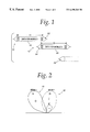
- FIG. 1 is a timing diagram illustrating transmission of multiple time slots in different directions in accordance with the invention
- FIG. 2 is a curve illustrating radiation patterns for transmitting first and second beams in accordance with the invention
- FIG. 3 illustrates transmission in two directions for a four-element antenna array in accordance with the invention.
- FIG. 4 is a block diagram of a base station in accordance with the invention.
- a time-division multiple access (TDMA) digital cellular base station uses a directive antenna array.
- the antenna array generates a number of directional transmissions directed towards mobile stations located at different azimuth angles to the base station site.
- a transmission to a given mobile station takes place in an allocated time slot of a TDMA frame period using an allocated radio carrier frequency.
- the transmission is directed toward the mobile station using the directional antenna array.
- the invention permits transmission of successive time slots on the same carrier frequency to occur in different directions or at different power levels while maintaining signal continuity as seen by receivers.
- D-AMPS digital advanced mobile phone system
- the transmission of a time slot in a given direction using the directional antenna array is extended to transmit the syncword in the following time slot, known as a postamble.
- the transmission of the following slot in a second direction commences by simultaneously transmitting the same syncword in the second direction, thus overlapping the extended transmission in the first direction.
- the first transmission is smoothly terminated by ramping its signal level to zero while transmitting the same data symbols that follow the syncword in the second slot.
- the second slot transmission commences smoothly by up-ramping its power level before transmission of its syncword, while transmitting the same data symbols as transmitted at the end of the first slot in the first direction.
- the second transmission may occur with a 90° phase shift relative to the first transmission with which it overlaps.
- transmission of a corresponding slot in successive TDMA frames occurs with an alternating 90° phase shift in alternate frames, or with a successive 90° phase rotation.
- the antenna array uses beam-forming weighting during transmission of the syncword occurring at the end of a first slot and the beginning of a second slot.
- the mobile station lying in the first direction receives that syncword with phase, amplitude and timing continuity to its slot's immediately preceding data symbols.
- the mobile station lying in the second direction receives the syncword with phase, amplitude and timing continuity to its slot's immediately following data symbols.
- the power level at which transmission in the second slot commences or at which transmission of the first slot terminates must be coordinated in dependence on the first and second directions and in particular in dependence on the difference in the directions. These power levels are coordinated to insure that each mobile station receives a signal level greater than or equal to a minimum acceptable signal level while transmitting the minimum total amount of power from the antenna array.
- a timing diagram illustrates a first transmission of a first beam 10 intended for a first mobile station and subsequent transmission of a second beam 12 intended for a second mobile station.
- a first time slot 14 comprises a first preamble syncword S 1 , followed by a first set of data symbols 16 and a postamble syncword S 2 .
- the beam 10 of the first transmission is transmitted to the first mobile station at a first power level in a first direction.
- the transmission of the first time slot is extended to include transmission of the postamble syncword S 2 .
- a second time slot 18 comprises a preamble syncword S 2 , which is the same as the first time slot's postamble syncword S 2 and overlaps with it in time.
- the second time slot also includes a second set of data symbols 20 and a postamble syncword S 3 .
- this implementation of the invention is characterized by transmitting the same syncword S 2 in two directions simultaneously during an overlapping period.
- the first transmission is smoothly ramped to zero power level after transmission of the second syncword S 2 as illustrated at 22 .
- the second transmission 12 is smoothly ramped up from a zero level before transmitting the syncword S 2 as illustrated at 24 .
- the same data symbols are modulated onto the overlapping transmissions.
- FIG. 1 also illustrates transmission of a third beam 26 that similarly overlaps the second transmission, as is apparent.
- the length of time of each of the up-ramping period 24 and the down-ramping period 22 is approximately one millisecond. Both times together represent about 30% of the D-AMPS' 6.6 millisecond burst duration, but only about 10% of the total power in the worst case when the first and second slots are of equal power level.
- a typical antenna array uses a left-right hermitian-symmetrical set of beam-forming weights.
- the radiation field from the array has the same phase in all directions apart from a change from + to ⁇ , i. e., from 0° to 180° passing through a radiation pattern null, thus the side lobe or amplitude a' in FIG. 2 has a sign of ⁇ , as compared with the main lobe or amplitude ‘a’ (Beam 1 ).
- a second beam transmitting the same data at the same time in a different direction may either add to or subtract from the radiation of the first beam in the second direction.
- the transmission of the second beam 12 is made to have a phase difference of 90° (as indicated by the imaginary scaling factor ‘j’ in Beam 2 ) with that of the first beam 10 , as illustrated in FIG. 2 .
- This avoids the uncertainty of whether the two beams will add constructively or destructively.
- the signal level received by each mobile station is the square root of the sum of the squares of contributions from each of the transmissions. The contributions are respectively the main beam contribution toward the mobile station for which the beam is intended and the side lobe contribution from the other beam in that direction.
- Square law addition is the deliberate result of the 90° phase shift between the two transmissions. This insures that the signal level received by each mobile station is at least equal to the desired level transmitted by one beam alone, when the power level has reached its stable value after up-ramping.
- the increase in signal level during the overlapped syncword transmission does not violate the desired cross-slot continuity, providing the power up-ramping and down-ramping occurs more slowly than signal level changes due to Rayleigh fading which the receiver is designed to expect.
- the rotation in phase of the resultant sum of the contributions from Beam 1 and Beam 2 in either direction does not biolate phase continuity providing the up and down-ramping are slower than expected fading.
- the receiver utilizes channel tracking which updates the reference amplitude and phase used for decoding after decoding each data symbol, and this channel tracking can then track the changes due to up-and down-ramping.
- signals can be transmitted from each array element, chosen such that the first mobile station receives the postamble syncword in the first direction at exactly the same level and phase as its preceding data symbols.
- a second mobile station receives the same syncword as its preamble in a second direction and at a second desired power level equal to the power level of the following data symbols.
- C.C# becomes singular. It may not then be efficient to attempt to transmit different signal levels to mobile stations lying in approximately the same direction, and it may take less total power to increase the lower of the two signal levels (a, b).
- a numerical example is provided for the case of the four-element array 30 in FIG. 3 . In the illustrated array 30 , to transmit in the two directions respectively, the four elements 32 , 33 , 34 and 35 are fed with signals
- the matrix C.C# can be calculated to be ⁇ [ 1 1 - ⁇ 1 - ⁇ 1 ]
- ⁇ i is the phase of element i for one of the beam directions.
- the total power to transmit a signal amplitude 1 in one direction and 0.5 in the mirror-image direction is given in Table 1 below in dBs relative to unit power for different beam squint angles, for a four-element array of omnidirectional radiators with 0.5 wavelength spacing.
- it is preferred to invert the sign of the second beam, selecting amplitudes of (a, b) (1, 0.5) with the result in Table 2 below:
- down-ramping can take place by ramping down both ‘a’ and ‘b’ from the higher level of b(opt) until ‘b’ reaches the target signal level for the second beam.
- to continue to ramp ‘a’ lower while maintaining ‘b’ may be inefficient unless the first beam direction is swung towards convergence with the second beam direction.
- the optimum solution can involve different ramping functions for each element, which are complicated functions of the actual antenna element characteristics.
- the complication may be unwarranted by the small increase in performance.
- the first implementation described above is preferred in which the first beam ramps down from its signal amplitude ‘a’ after completing transmission of the second syncword, while the second beam ramps up from zero smoothly to its amplitude “jb” before transmission of the same syncword, where “jb” signifies a signal amplitude of “b” combined with a phase shift of 90° relative to the first beam.
- FIG. 4 a block diagram illustrates a base station 50 for implementing the system and method according to the invention.
- the base station 50 includes a digital signal processor 52 connected to a memory 54 .
- the memory 54 stores programs implemented by the processor 52 for slot, frequency and beam direction allocations.
- the processor receives data signals from a block 56 to be transmitted to different receivers in the form of mobile stations.
- the processor 52 is connected via a modulator bank 58 to a beam-forming network 60 .
- the beam-forming network 60 is connected via a set of linear column amplifiers 62 to an antenna array 64 .
- the antenna array 64 comprises an array of antenna elements 66 , such as patch elements, which are printed on a sheet 68 of stripline material.
- the elements 66 in each of four columns 68 , 69 , 70 and 71 are interconnected in phase by a phasing line (not shown) to form a co-linear array having vertical directivity, in a conventional manner.
- the modulator bank 58 consists of a first modulator 58 - 1 for beam 1 , a second modulator 58 - 2 for beam 2 , a third modulator 58 - 3 for beam 3 and a fourth modulator 58 - 4 for beam 3 .
- the linear column amplifiers 62 comprise a first amplifier 62 - 1 , a second amplifier 62 - 2 , a third amplifier 62 - 3 and a fourth amplifier 62 - 4 .
- the four columns 68 - 71 are driven by the respective power amplifiers 62 - 1 to 62 - 4 .
- the power amplifiers referred to generally as 62
- the fixed beam-forming network 60 is used at the input of the set of power amplifiers 62 to accept signals for radiation in a particular direction and to split the input signal in phase between its four outputs such that the radiation from the antenna array 64 will be in the desired direction.
- Other inputs to the Butler matrix 60 are used for transmission in other directions.
- the Butler matrix 60 can have more than four inputs, for example eight inputs, and it would then have a corresponding number of outputs, of which only four are connected to the power amplifiers 62 . This allows more than four different directions to be defined, the extra beams then overlapping the original four beams substantially.
- An adaptive channel allocation device (not shown) allocates the frequency, time slot and direction to be used for each call to minimize interference with other ongoing calls transmitted from the same or other similar base station sites nearby.
- Signals for transmission in the same direction using different carrier frequencies are generated using the digital signal processor 52 , from the data signals 56 , added and then jointly modulated using the modulator bank 58 to form the signals for application to the Butler matrix 60 .
- the digital signal processor 52 can implement the function of the Butler matrix 60 and perform it numerically thus eliminating the need for the block 60 . When this is done, transmission is no longer restricted to a finite number of pre-determined beam directions, but each signal in each time slot and on each frequency may be independently controlled in beam directions so as to maximize the signal quality received by the intended receivers.
- a simplified method of digital transmit beam-forming is described in Dent U.S. Pat. No. 5,909,460, the specification of which is incorporated by reference herein.
- the processor 52 includes the functions of error coding, modulation, beam-forming, digital frequency-shifting to an allocated channel and digital frequency division multiplexing of signals on different frequency channels to form array drive signals.
- the array drive signals are then D/A converted and modulated to the desired radio frequency band.
- the center of the band is defined by a radio frequency signal from a frequency synthesizer 64 associated with the modulator bank 58 .
- the processor 52 can also be programed to apply the up-ramping and down-ramping of the signals for different time slots and different beams to implement the method of the invention.
Landscapes
- Engineering & Computer Science (AREA)
- Computer Networks & Wireless Communication (AREA)
- Signal Processing (AREA)
- Mobile Radio Communication Systems (AREA)
- Variable-Direction Aerials And Aerial Arrays (AREA)
- Time-Division Multiplex Systems (AREA)
- Radio Transmission System (AREA)
Priority Applications (8)
| Application Number | Priority Date | Filing Date | Title |
|---|---|---|---|
| US09/429,463 US6490261B1 (en) | 1999-10-28 | 1999-10-28 | Overlapping slot transmission using phased arrays |
| PCT/US2000/027230 WO2001031811A1 (en) | 1999-10-28 | 2000-10-03 | Overlapping slot transmission using phased arrays |
| DE60016966T DE60016966T2 (de) | 1999-10-28 | 2000-10-03 | Übertragung von überlappenden zeitschlitzen mit phasengesteuerten gruppenantennen |
| CNB008149887A CN1153373C (zh) | 1999-10-28 | 2000-10-03 | 使用相控阵的重叠时隙发送的方法和系统 |
| AT00967275T ATE285638T1 (de) | 1999-10-28 | 2000-10-03 | Übertragung von überlappenden zeitschlitzen mit phasengesteuerten gruppenantennen |
| AU77496/00A AU7749600A (en) | 1999-10-28 | 2000-10-03 | Overlapping slot transmission using phased arrays |
| EP00967275A EP1230746B1 (de) | 1999-10-28 | 2000-10-03 | Übertragung von überlappenden zeitschlitzen mit phasengesteuerten gruppenantennen |
| JP2001533651A JP4523218B2 (ja) | 1999-10-28 | 2000-10-03 | フェーズド・アレーを使用する重なりスロット伝送 |
Applications Claiming Priority (1)
| Application Number | Priority Date | Filing Date | Title |
|---|---|---|---|
| US09/429,463 US6490261B1 (en) | 1999-10-28 | 1999-10-28 | Overlapping slot transmission using phased arrays |
Publications (1)
| Publication Number | Publication Date |
|---|---|
| US6490261B1 true US6490261B1 (en) | 2002-12-03 |
Family
ID=23703363
Family Applications (1)
| Application Number | Title | Priority Date | Filing Date |
|---|---|---|---|
| US09/429,463 Expired - Fee Related US6490261B1 (en) | 1999-10-28 | 1999-10-28 | Overlapping slot transmission using phased arrays |
Country Status (8)
| Country | Link |
|---|---|
| US (1) | US6490261B1 (de) |
| EP (1) | EP1230746B1 (de) |
| JP (1) | JP4523218B2 (de) |
| CN (1) | CN1153373C (de) |
| AT (1) | ATE285638T1 (de) |
| AU (1) | AU7749600A (de) |
| DE (1) | DE60016966T2 (de) |
| WO (1) | WO2001031811A1 (de) |
Cited By (20)
| Publication number | Priority date | Publication date | Assignee | Title |
|---|---|---|---|---|
| US20010034236A1 (en) * | 2000-01-18 | 2001-10-25 | Wen Tong | Multi-beam antenna system for high speed data |
| US20040090947A1 (en) * | 2002-11-07 | 2004-05-13 | Wilborn Thomas B. | Method, apparatus, and system for receiving data on a first frequency band and observing a second frequency band |
| US20040114564A1 (en) * | 2001-05-28 | 2004-06-17 | Frank Gersemsky | Data transmission system having a high data transmission rate and method of transmitting the data |
| US6873613B1 (en) * | 2000-10-16 | 2005-03-29 | Ericsson Inc. | Methods for wirelessly communicating time division multiple access (TDMA) data using adaptive multiplexing and coding |
| US20050075141A1 (en) * | 2003-06-19 | 2005-04-07 | Ipr Licensing, Inc. | Antenna steering for an access point based upon probe signals |
| US20050281353A1 (en) * | 2004-06-18 | 2005-12-22 | Huang Shine C | Method and apparatus for controlling a TX power amplifier |
| US20050282507A1 (en) * | 2004-06-18 | 2005-12-22 | Mediatek Incorporation | Method and apparatus for controlling a TX power amplifier |
| US20060285582A1 (en) * | 2003-11-14 | 2006-12-21 | Atsushi Sumasu | Transmission device and gain control method |
| US20070002805A1 (en) * | 2005-06-29 | 2007-01-04 | Nokia Corporation | Control of antenna pattern |
| US20100031303A1 (en) * | 2006-09-30 | 2010-02-04 | Jin Fei Yu | Headend apparatus for data transmission over cable access network |
| US20100246531A1 (en) * | 2007-10-23 | 2010-09-30 | Sung Cheol Chang | Method for transmitting signals |
| WO2018005215A1 (en) * | 2016-07-01 | 2018-01-04 | Intel IP Corporation | Group-addressed transmission techniques for directional wireless networks |
| US10334549B2 (en) * | 2003-02-14 | 2019-06-25 | Apple Inc. | Wireless communication |
| US10686504B2 (en) | 2016-11-04 | 2020-06-16 | Asustek Computer Inc. | Method and apparatus for user equipment beamforming operation in a wireless communication system |
| US11165485B2 (en) * | 2017-08-10 | 2021-11-02 | Comcast Cable Communications, Llc | Priority of beam failure recovery request and uplink channels |
| US11337265B2 (en) | 2017-08-10 | 2022-05-17 | Comcast Cable Communications, Llc | Beam failure recovery request transmission |
| US11425774B2 (en) | 2017-08-10 | 2022-08-23 | Comcast Cable Communications, Llc | Transmission power control for beam failure recovery requests |
| US20230057504A1 (en) * | 2020-02-18 | 2023-02-23 | Zeku, Inc. | Smooth transition for data streams with adjusted gain |
| US11950287B2 (en) | 2017-08-10 | 2024-04-02 | Comcast Cable Communications, Llc | Resource configuration of beam failure recovery request transmission |
| US12615078B2 (en) | 2024-02-07 | 2026-04-28 | Bloomsbury Design Labs Llc | Priority of beam failure recovery request and uplink channels |
Families Citing this family (6)
| Publication number | Priority date | Publication date | Assignee | Title |
|---|---|---|---|---|
| US7248217B2 (en) * | 2005-08-31 | 2007-07-24 | Tzero Technologies, Inc. | Average EIRP control of multiple antenna transmission signals |
| JP4753750B2 (ja) * | 2006-03-06 | 2011-08-24 | 株式会社日立製作所 | 無線通信方式および無線基地局装置 |
| EP2039195B1 (de) * | 2006-07-07 | 2015-02-18 | Telefonaktiebolaget LM Ericsson (publ) | Ressourcenplanung in drahtlosen kommunikationssystemen unter verwendung von strahlformung |
| JP5578885B2 (ja) * | 2010-02-26 | 2014-08-27 | 三菱重工業株式会社 | フェーズドアレイアンテナ及びその制御方法 |
| EP3503650B1 (de) * | 2017-12-21 | 2020-07-22 | ASUSTek Computer Inc. | Verfahren und vorrichtung zum senden und empfangen in einer backhaul-verbindung in einem drahtloskommunikationssystem |
| EP3977560B1 (de) | 2019-05-28 | 2025-08-06 | CoreHW Semiconductor Oy | Weiche antennenumschaltlösung eines aod-peilsenders |
Citations (18)
| Publication number | Priority date | Publication date | Assignee | Title |
|---|---|---|---|---|
| US4513412A (en) | 1983-04-25 | 1985-04-23 | At&T Bell Laboratories | Time division adaptive retransmission technique for portable radio telephones |
| US4866710A (en) | 1988-02-22 | 1989-09-12 | Motorola, Inc. | Reuse groups for scan monitoring in digital cellular systems |
| US5303240A (en) * | 1991-07-08 | 1994-04-12 | Motorola, Inc. | Telecommunications system using directional antennas |
| US5335250A (en) | 1992-10-22 | 1994-08-02 | Ericsson Ge Mobile Communications Inc. | Method and apparatus for bidirectional demodulation of digitally modulated signals |
| US5539730A (en) | 1994-01-11 | 1996-07-23 | Ericsson Ge Mobile Communications Inc. | TDMA/FDMA/CDMA hybrid radio access methods |
| US5548813A (en) | 1994-03-24 | 1996-08-20 | Ericsson Inc. | Phased array cellular base station and associated methods for enhanced power efficiency |
| US5555271A (en) | 1993-12-27 | 1996-09-10 | Sanyo Electric Co., Ltd. | Semiconductor laser device |
| US5579306A (en) | 1994-09-01 | 1996-11-26 | Ericsson Inc. | Time and frequency slot allocation system and method |
| US5594941A (en) | 1994-01-11 | 1997-01-14 | Ericsson Inc. | A cellular/satellite communications system with generation of a plurality of sets of intersecting antenna beams |
| US5604730A (en) * | 1994-07-25 | 1997-02-18 | Qualcomm Incorporated | Remote transmitter power control in a contention based multiple access system |
| US5740165A (en) * | 1996-02-29 | 1998-04-14 | Lucent Technologies Inc. | Wireless TDMA transmitter with reduced interference |
| WO1999001949A1 (en) | 1997-07-03 | 1999-01-14 | Telefonaktiebolaget Lm Ericsson (Publ) | Power control apparatus, and an associated method, for tdma transmitter |
| US5909460A (en) | 1995-12-07 | 1999-06-01 | Ericsson, Inc. | Efficient apparatus for simultaneous modulation and digital beamforming for an antenna array |
| US5983112A (en) | 1990-12-06 | 1999-11-09 | Hughes Electronics Corporation | Frequency, time and power level diversity system for digital radio telephony |
| US6072788A (en) | 1997-04-07 | 2000-06-06 | Metawave Communications Corporation | Forward link TDMA power control system and method |
| US6094165A (en) * | 1997-07-31 | 2000-07-25 | Nortel Networks Corporation | Combined multi-beam and sector coverage antenna array |
| US6301238B1 (en) * | 1997-01-28 | 2001-10-09 | Telefonaktiebolaget Lm Ericsson (Publ) | Directional-beam generative apparatus and associated method |
| US6377558B1 (en) * | 1998-04-06 | 2002-04-23 | Ericsson Inc. | Multi-signal transmit array with low intermodulation |
Family Cites Families (1)
| Publication number | Priority date | Publication date | Assignee | Title |
|---|---|---|---|---|
| JP3272961B2 (ja) * | 1996-08-02 | 2002-04-08 | 株式会社日立国際電気 | アダプティブアレーアンテナ |
-
1999
- 1999-10-28 US US09/429,463 patent/US6490261B1/en not_active Expired - Fee Related
-
2000
- 2000-10-03 WO PCT/US2000/027230 patent/WO2001031811A1/en not_active Ceased
- 2000-10-03 EP EP00967275A patent/EP1230746B1/de not_active Expired - Lifetime
- 2000-10-03 DE DE60016966T patent/DE60016966T2/de not_active Expired - Lifetime
- 2000-10-03 JP JP2001533651A patent/JP4523218B2/ja not_active Expired - Fee Related
- 2000-10-03 AU AU77496/00A patent/AU7749600A/en not_active Abandoned
- 2000-10-03 CN CNB008149887A patent/CN1153373C/zh not_active Expired - Fee Related
- 2000-10-03 AT AT00967275T patent/ATE285638T1/de not_active IP Right Cessation
Patent Citations (21)
| Publication number | Priority date | Publication date | Assignee | Title |
|---|---|---|---|---|
| US4513412A (en) | 1983-04-25 | 1985-04-23 | At&T Bell Laboratories | Time division adaptive retransmission technique for portable radio telephones |
| US4866710A (en) | 1988-02-22 | 1989-09-12 | Motorola, Inc. | Reuse groups for scan monitoring in digital cellular systems |
| US5983112A (en) | 1990-12-06 | 1999-11-09 | Hughes Electronics Corporation | Frequency, time and power level diversity system for digital radio telephony |
| US5303240A (en) * | 1991-07-08 | 1994-04-12 | Motorola, Inc. | Telecommunications system using directional antennas |
| US5335250A (en) | 1992-10-22 | 1994-08-02 | Ericsson Ge Mobile Communications Inc. | Method and apparatus for bidirectional demodulation of digitally modulated signals |
| US5555271A (en) | 1993-12-27 | 1996-09-10 | Sanyo Electric Co., Ltd. | Semiconductor laser device |
| US5619503A (en) | 1994-01-11 | 1997-04-08 | Ericsson Inc. | Cellular/satellite communications system with improved frequency re-use |
| US5539730A (en) | 1994-01-11 | 1996-07-23 | Ericsson Ge Mobile Communications Inc. | TDMA/FDMA/CDMA hybrid radio access methods |
| US5566168A (en) | 1994-01-11 | 1996-10-15 | Ericsson Ge Mobile Communications Inc. | TDMA/FDMA/CDMA hybrid radio access methods |
| US5594941A (en) | 1994-01-11 | 1997-01-14 | Ericsson Inc. | A cellular/satellite communications system with generation of a plurality of sets of intersecting antenna beams |
| US5548813A (en) | 1994-03-24 | 1996-08-20 | Ericsson Inc. | Phased array cellular base station and associated methods for enhanced power efficiency |
| US5604730A (en) * | 1994-07-25 | 1997-02-18 | Qualcomm Incorporated | Remote transmitter power control in a contention based multiple access system |
| US5579306A (en) | 1994-09-01 | 1996-11-26 | Ericsson Inc. | Time and frequency slot allocation system and method |
| US5909460A (en) | 1995-12-07 | 1999-06-01 | Ericsson, Inc. | Efficient apparatus for simultaneous modulation and digital beamforming for an antenna array |
| US5740165A (en) * | 1996-02-29 | 1998-04-14 | Lucent Technologies Inc. | Wireless TDMA transmitter with reduced interference |
| US6301238B1 (en) * | 1997-01-28 | 2001-10-09 | Telefonaktiebolaget Lm Ericsson (Publ) | Directional-beam generative apparatus and associated method |
| US6072788A (en) | 1997-04-07 | 2000-06-06 | Metawave Communications Corporation | Forward link TDMA power control system and method |
| WO1999001949A1 (en) | 1997-07-03 | 1999-01-14 | Telefonaktiebolaget Lm Ericsson (Publ) | Power control apparatus, and an associated method, for tdma transmitter |
| US6072792A (en) * | 1997-07-03 | 2000-06-06 | Telefonaktiebolaget Lm Ericsson | Power control apparatus, and an associated method, for TDMA transmitter |
| US6094165A (en) * | 1997-07-31 | 2000-07-25 | Nortel Networks Corporation | Combined multi-beam and sector coverage antenna array |
| US6377558B1 (en) * | 1998-04-06 | 2002-04-23 | Ericsson Inc. | Multi-signal transmit array with low intermodulation |
Non-Patent Citations (2)
| Title |
|---|
| U.S. patent application Ser. No. 08/218,236, Dent et al., pending. |
| U.S. patent application Ser. No. 08/887,726, Mazur et al., pending. |
Cited By (37)
| Publication number | Priority date | Publication date | Assignee | Title |
|---|---|---|---|---|
| US6804521B2 (en) * | 2000-01-18 | 2004-10-12 | Nortel Networks Limited | Multi-beam antenna system for high speed data |
| US20010034236A1 (en) * | 2000-01-18 | 2001-10-25 | Wen Tong | Multi-beam antenna system for high speed data |
| US6873613B1 (en) * | 2000-10-16 | 2005-03-29 | Ericsson Inc. | Methods for wirelessly communicating time division multiple access (TDMA) data using adaptive multiplexing and coding |
| US7260413B2 (en) * | 2001-05-28 | 2007-08-21 | Infineon Technologies Ag. | Data transmission system having a high data transmission rate and method of transmitting the data |
| US20040114564A1 (en) * | 2001-05-28 | 2004-06-17 | Frank Gersemsky | Data transmission system having a high data transmission rate and method of transmitting the data |
| US20040090947A1 (en) * | 2002-11-07 | 2004-05-13 | Wilborn Thomas B. | Method, apparatus, and system for receiving data on a first frequency band and observing a second frequency band |
| US7499428B2 (en) * | 2002-11-07 | 2009-03-03 | Qualcomm, Incorporated | Method, apparatus, and system for receiving data on a first frequency band and observing a second frequency band |
| US10334549B2 (en) * | 2003-02-14 | 2019-06-25 | Apple Inc. | Wireless communication |
| US20050075141A1 (en) * | 2003-06-19 | 2005-04-07 | Ipr Licensing, Inc. | Antenna steering for an access point based upon probe signals |
| US7047046B2 (en) * | 2003-06-19 | 2006-05-16 | Ipr Licensing, Inc. | Antenna steering for an access point based upon probe signals |
| US20060285582A1 (en) * | 2003-11-14 | 2006-12-21 | Atsushi Sumasu | Transmission device and gain control method |
| US7418242B2 (en) * | 2003-11-14 | 2008-08-26 | Matsushita Electric Industrial Co., Ltd. | Transmission device and gain control method |
| US7489908B2 (en) | 2004-06-18 | 2009-02-10 | Mediatek Incorporation | Method and apparatus for controlling a TX power amplifier |
| US20080039033A1 (en) * | 2004-06-18 | 2008-02-14 | Huang Shine C | Method and apparatus for controlling a TX power amplifier |
| US20080045165A1 (en) * | 2004-06-18 | 2008-02-21 | Huang Shine C | Method and apparatus for controlling a TX power amplifier |
| US7486938B2 (en) | 2004-06-18 | 2009-02-03 | Mediatek Incorporation | Method and apparatus for controlling a TX power amplifier |
| US7489909B2 (en) | 2004-06-18 | 2009-02-10 | Mediatek Incorporation | Method and apparatus for controlling a TX power amplifier |
| US20050282508A1 (en) * | 2004-06-18 | 2005-12-22 | Mediatek Incorporation | Method and apparatus for controlling a TX power amplifier |
| US20050282507A1 (en) * | 2004-06-18 | 2005-12-22 | Mediatek Incorporation | Method and apparatus for controlling a TX power amplifier |
| US20050281353A1 (en) * | 2004-06-18 | 2005-12-22 | Huang Shine C | Method and apparatus for controlling a TX power amplifier |
| US20070002805A1 (en) * | 2005-06-29 | 2007-01-04 | Nokia Corporation | Control of antenna pattern |
| US20100031303A1 (en) * | 2006-09-30 | 2010-02-04 | Jin Fei Yu | Headend apparatus for data transmission over cable access network |
| US20100246531A1 (en) * | 2007-10-23 | 2010-09-30 | Sung Cheol Chang | Method for transmitting signals |
| US8675600B2 (en) * | 2007-10-23 | 2014-03-18 | Samsung Electronics Co., Ltd. | Method for transmitting signals |
| WO2018005215A1 (en) * | 2016-07-01 | 2018-01-04 | Intel IP Corporation | Group-addressed transmission techniques for directional wireless networks |
| US10686504B2 (en) | 2016-11-04 | 2020-06-16 | Asustek Computer Inc. | Method and apparatus for user equipment beamforming operation in a wireless communication system |
| US11165485B2 (en) * | 2017-08-10 | 2021-11-02 | Comcast Cable Communications, Llc | Priority of beam failure recovery request and uplink channels |
| US11337265B2 (en) | 2017-08-10 | 2022-05-17 | Comcast Cable Communications, Llc | Beam failure recovery request transmission |
| US11425774B2 (en) | 2017-08-10 | 2022-08-23 | Comcast Cable Communications, Llc | Transmission power control for beam failure recovery requests |
| US11870724B2 (en) | 2017-08-10 | 2024-01-09 | Comcast Cable Communications, Llc | Beam failure recovery request transmission |
| US11950287B2 (en) | 2017-08-10 | 2024-04-02 | Comcast Cable Communications, Llc | Resource configuration of beam failure recovery request transmission |
| US11949487B2 (en) | 2017-08-10 | 2024-04-02 | Comcast Cable Communications, Llc | Priority of beam failure recovery request and uplink channels |
| US11950309B2 (en) | 2017-08-10 | 2024-04-02 | Comcast Cable Communications, Llc | Transmission power control for beam failure recovery requests |
| US12341719B2 (en) | 2017-08-10 | 2025-06-24 | Comcast Cable Communications, Llc | Beam failure recovery request transmission |
| US20230057504A1 (en) * | 2020-02-18 | 2023-02-23 | Zeku, Inc. | Smooth transition for data streams with adjusted gain |
| US11881972B2 (en) * | 2020-02-18 | 2024-01-23 | Zeku Technology (Shanghai) Corp., Ltd. | Smooth transition for data streams with adjusted gain |
| US12615078B2 (en) | 2024-02-07 | 2026-04-28 | Bloomsbury Design Labs Llc | Priority of beam failure recovery request and uplink channels |
Also Published As
| Publication number | Publication date |
|---|---|
| DE60016966T2 (de) | 2005-05-19 |
| EP1230746A1 (de) | 2002-08-14 |
| EP1230746B1 (de) | 2004-12-22 |
| JP2003513507A (ja) | 2003-04-08 |
| JP4523218B2 (ja) | 2010-08-11 |
| CN1153373C (zh) | 2004-06-09 |
| DE60016966D1 (de) | 2005-01-27 |
| WO2001031811A1 (en) | 2001-05-03 |
| CN1385010A (zh) | 2002-12-11 |
| ATE285638T1 (de) | 2005-01-15 |
| AU7749600A (en) | 2001-05-08 |
Similar Documents
| Publication | Publication Date | Title |
|---|---|---|
| US6490261B1 (en) | Overlapping slot transmission using phased arrays | |
| US5649287A (en) | Orthogonalizing methods for antenna pattern nullfilling | |
| US6463301B1 (en) | Base stations for use in cellular communications systems | |
| US6185440B1 (en) | Method for sequentially transmitting a downlink signal from a communication station that has an antenna array to achieve an omnidirectional radiation | |
| US9806777B1 (en) | Communication device and a method for beamforming | |
| US6791507B2 (en) | Feed network for simultaneous generation of narrow and wide beams with a rotational-symmetric antenna | |
| EP3266118B1 (de) | Verfahren, steuerungssystem und kommunikationssystem zur anpassung von strahlmustern | |
| US6218987B1 (en) | Radio antenna system | |
| US9362991B2 (en) | Apparatus, system and method of transmit power control for wireless communication | |
| US6336033B1 (en) | Adaptive array antenna | |
| EP0647978B1 (de) | Antenneneinrichtung für Basisstation | |
| US5771017A (en) | Base station antenna arrangement | |
| US6795018B2 (en) | Smart antenna arrays | |
| CN100380734C (zh) | 具有共同开销的码分多址基站天线系统 | |
| US7299071B1 (en) | Downlink broadcasting by sequential transmissions from a communication station having an antenna array | |
| CN101848021B (zh) | 一种智能天线阵广播波束权值的生成方法和装置 | |
| Girnyk et al. | Broad beamforming technology in 5G massive MIMO | |
| US20250202646A1 (en) | Synchronization signal block for multi-beam communication with large antenna arrays | |
| Pan et al. | Downlink multi-user algorithms for millimeter-wave wideband linear arrays on PD-NOMA-based squint steering beams | |
| US6542519B1 (en) | Intentional sidelobe creation | |
| US20240162954A1 (en) | Communication apparatus | |
| Prasad et al. | Multi-beam multi-channel secure communication using a mmwave analog phased array beamformer | |
| Artiga et al. | Pragmatic Earth-Fixed Beam Management for 3GPP NTN Common Signaling in LEO Satellites | |
| Raghavan et al. | Active Antenna System (AAS) Optimization for Coexistence Considerations | |
| MXPA97007231A (en) | Antenna lobulo an |
Legal Events
| Date | Code | Title | Description |
|---|---|---|---|
| AS | Assignment |
Owner name: ERICSSON INC., NORTH CAROLINA Free format text: ASSIGNMENT OF ASSIGNORS INTEREST;ASSIGNORS:DENT, PAUL W.;MOLNAR, KARL J.;REEL/FRAME:010403/0960 Effective date: 19991025 |
|
| FPAY | Fee payment |
Year of fee payment: 4 |
|
| FPAY | Fee payment |
Year of fee payment: 8 |
|
| AS | Assignment |
Owner name: CLUSTER LLC, DELAWARE Free format text: ASSIGNMENT OF ASSIGNORS INTEREST;ASSIGNOR:ERICSSON INC.;REEL/FRAME:030192/0273 Effective date: 20130211 |
|
| AS | Assignment |
Owner name: UNWIRED PLANET, LLC, NEVADA Free format text: ASSIGNMENT OF ASSIGNORS INTEREST;ASSIGNOR:CLUSTER LLC;REEL/FRAME:030201/0389 Effective date: 20130213 |
|
| AS | Assignment |
Owner name: CLUSTER LLC, SWEDEN Free format text: NOTICE OF GRANT OF SECURITY INTEREST IN PATENTS;ASSIGNOR:UNWIRED PLANET, LLC;REEL/FRAME:030369/0601 Effective date: 20130213 |
|
| FEPP | Fee payment procedure |
Free format text: PAYOR NUMBER ASSIGNED (ORIGINAL EVENT CODE: ASPN); ENTITY STATUS OF PATENT OWNER: LARGE ENTITY |
|
| REMI | Maintenance fee reminder mailed | ||
| LAPS | Lapse for failure to pay maintenance fees | ||
| STCH | Information on status: patent discontinuation |
Free format text: PATENT EXPIRED DUE TO NONPAYMENT OF MAINTENANCE FEES UNDER 37 CFR 1.362 |
|
| FP | Lapsed due to failure to pay maintenance fee |
Effective date: 20141203 |