US6468116B2 - Terminal fitting - Google Patents

Terminal fitting Download PDF

Info

Publication number
US6468116B2
US6468116B2 US09/776,338 US77633801A US6468116B2 US 6468116 B2 US6468116 B2 US 6468116B2 US 77633801 A US77633801 A US 77633801A US 6468116 B2 US6468116 B2 US 6468116B2
Authority
US
United States
Prior art keywords
crimping piece
crimping
wire
terminal fitting
leading end
Prior art date
Legal status (The legal status is an assumption and is not a legal conclusion. Google has not performed a legal analysis and makes no representation as to the accuracy of the status listed.)
Expired - Fee Related
Application number
US09/776,338
Other versions
US20010016460A1 (en
Inventor
Takashi Koide
Current Assignee (The listed assignees may be inaccurate. Google has not performed a legal analysis and makes no representation or warranty as to the accuracy of the list.)
Sumitomo Wiring Systems Ltd
Original Assignee
Sumitomo Wiring Systems Ltd
Priority date (The priority date is an assumption and is not a legal conclusion. Google has not performed a legal analysis and makes no representation as to the accuracy of the date listed.)
Filing date
Publication date
Application filed by Sumitomo Wiring Systems Ltd filed Critical Sumitomo Wiring Systems Ltd
Assigned to SUMITOMO WIRING SYSTEMS, LTD. reassignment SUMITOMO WIRING SYSTEMS, LTD. ASSIGNMENT OF ASSIGNORS INTEREST (SEE DOCUMENT FOR DETAILS). Assignors: KOIDE, TAKASHI
Publication of US20010016460A1 publication Critical patent/US20010016460A1/en
Application granted granted Critical
Publication of US6468116B2 publication Critical patent/US6468116B2/en
Anticipated expiration legal-status Critical
Expired - Fee Related legal-status Critical Current

Links

Images

Classifications

    • HELECTRICITY
    • H01ELECTRIC ELEMENTS
    • H01RELECTRICALLY-CONDUCTIVE CONNECTIONS; STRUCTURAL ASSOCIATIONS OF A PLURALITY OF MUTUALLY-INSULATED ELECTRICAL CONNECTING ELEMENTS; COUPLING DEVICES; CURRENT COLLECTORS
    • H01R4/00Electrically-conductive connections between two or more conductive members in direct contact, i.e. touching one another; Means for effecting or maintaining such contact; Electrically-conductive connections having two or more spaced connecting locations for conductors and using contact members penetrating insulation
    • H01R4/10Electrically-conductive connections between two or more conductive members in direct contact, i.e. touching one another; Means for effecting or maintaining such contact; Electrically-conductive connections having two or more spaced connecting locations for conductors and using contact members penetrating insulation effected solely by twisting, wrapping, bending, crimping, or other permanent deformation
    • H01R4/18Electrically-conductive connections between two or more conductive members in direct contact, i.e. touching one another; Means for effecting or maintaining such contact; Electrically-conductive connections having two or more spaced connecting locations for conductors and using contact members penetrating insulation effected solely by twisting, wrapping, bending, crimping, or other permanent deformation by crimping
    • H01R4/183Electrically-conductive connections between two or more conductive members in direct contact, i.e. touching one another; Means for effecting or maintaining such contact; Electrically-conductive connections having two or more spaced connecting locations for conductors and using contact members penetrating insulation effected solely by twisting, wrapping, bending, crimping, or other permanent deformation by crimping for cylindrical elongated bodies, e.g. cables having circular cross-section
    • H01R4/184Electrically-conductive connections between two or more conductive members in direct contact, i.e. touching one another; Means for effecting or maintaining such contact; Electrically-conductive connections having two or more spaced connecting locations for conductors and using contact members penetrating insulation effected solely by twisting, wrapping, bending, crimping, or other permanent deformation by crimping for cylindrical elongated bodies, e.g. cables having circular cross-section comprising a U-shaped wire-receiving portion
    • HELECTRICITY
    • H01ELECTRIC ELEMENTS
    • H01RELECTRICALLY-CONDUCTIVE CONNECTIONS; STRUCTURAL ASSOCIATIONS OF A PLURALITY OF MUTUALLY-INSULATED ELECTRICAL CONNECTING ELEMENTS; COUPLING DEVICES; CURRENT COLLECTORS
    • H01R4/00Electrically-conductive connections between two or more conductive members in direct contact, i.e. touching one another; Means for effecting or maintaining such contact; Electrically-conductive connections having two or more spaced connecting locations for conductors and using contact members penetrating insulation
    • H01R4/10Electrically-conductive connections between two or more conductive members in direct contact, i.e. touching one another; Means for effecting or maintaining such contact; Electrically-conductive connections having two or more spaced connecting locations for conductors and using contact members penetrating insulation effected solely by twisting, wrapping, bending, crimping, or other permanent deformation
    • H01R4/18Electrically-conductive connections between two or more conductive members in direct contact, i.e. touching one another; Means for effecting or maintaining such contact; Electrically-conductive connections having two or more spaced connecting locations for conductors and using contact members penetrating insulation effected solely by twisting, wrapping, bending, crimping, or other permanent deformation by crimping
    • H01R4/188Electrically-conductive connections between two or more conductive members in direct contact, i.e. touching one another; Means for effecting or maintaining such contact; Electrically-conductive connections having two or more spaced connecting locations for conductors and using contact members penetrating insulation effected solely by twisting, wrapping, bending, crimping, or other permanent deformation by crimping having an uneven wire-receiving surface to improve the contact

Definitions

  • the present invention relates to a terminal fitting that can be crimped into connection with a wire.
  • a terminal fitting that can be crimped into connection with a wire is disclosed in Japanese Unexamined Patent Publication No. 4-209471, and is identified generally by the numeral 100 in FIGS. 9 to 13 of this application.
  • the terminal fitting 100 has a barrel-type wire-fastening portion 101 with a bottom wall 102 and first and second fastening pieces 103 , 104 that extend upward from the left and right side edges of the bottom wall 102 .
  • An automated apparatus is used to crimp the wire-fastening portion 101 into connection with a wire 105 .
  • the wire-fastening portion 101 is placed on an anvil 106 and the wire 105 is placed between the two fastening pieces 103 , 104 .
  • a crimper 107 is located above the anvil 106 and is provided with an arch-shaped guide surface 108 formed with a stepped stopper 109 substantially at the uppermost position. The crimper 107 then is lowered to crimp the fastening pieces 103 , 104 to the wire 105 .
  • first and second crimping pieces 103 , 104 are bent inwardly. More particularly, the first crimping piece 103 departs from the stopper 109 and is bent along the guide surface 108 with a decreasing radius of curvature. Simultaneously, the second crimping piece 104 is bent along the inner side surface of the first crimping piece 103 with a decreasing radius of curvature. As a result, the first and second crimping pieces 103 , 104 are crimped and fastened to the outer circumferential surface of the wire 105 .
  • the crimping of the terminal fitting 100 may cause the leading end 104 A of the second crimping piece 104 to be bent away from the intended bending direction, as shown in FIGS. 11 and 12, and into a reverse fold, as shown in FIG. 13 . If this occurs, the folded leading end 104 A may be broken along the fold and may come out through a clearance between the first crimping piece 103 and the wire 105 . As a result, a clearance may be formed between the first crimping piece 103 and the wire 105 , and a reduced fastening force may result.
  • an object of the present invention is to securely crimp crimping pieces into connection with a wire.
  • the subject invention is directed to a terminal fitting that comprises a wire-fastening portion with a bottom wall and at least first and second crimping pieces that extend from the bottom wall.
  • the wire-fastening portion can be crimped into connection with a wire such that the second crimping piece is deformed to reduce a radius of curvature while moving substantially along the inner side surface of the first crimping piece.
  • the first and second crimping pieces substantially surround the outer circumferential surface of the wire.
  • the second crimping piece is recessed to form a deformation-facilitating portion or a weakened portion that facilitates a bending or deformation that inclines a leading end portion of the second crimping piece inwardly. Accordingly, a crimping error that deforms the leading edge in a direction opposite from an intended direction can be prevented.
  • the second crimping piece is formed with a projection on the inner side surface.
  • the projection is dimensioned and configured to bite into the outer circumferential surface of the wire.
  • the deformation-facilitating portion preferably is formed between the projection and the leading end of the second crimping piece. Accordingly, the second crimping piece is bent between the leading edge and the projection to incline the leading edge inwardly. Angles of inclination of the bent leading end with respect to a guide surface and the first crimping piece are small as compared to a case where the second crimping piece is bent between the bottom wall and the upper projection. Thus, the second crimping piece is moved smoothly along the inner side surface of the first crimping piece to reduce a diameter.
  • the deformation-facilitating portion may comprise a groove that extends along at least one side surface of the second crimping piece, and preferably along the inner side surface of the second crimping piece. Additionally, the groove preferably is aligned substantially normal to the extension of the second crimping piece. Thus the groove lies substantially along a bending line, and bending can be performed more securely.
  • the leading end of the second crimping piece is bent about a point on the outer side surface of the second crimping piece that substantially aligns with the deformation-facilitating portion. Additionally, the groove is open in the inner side surface. Accordingly, there is no likelihood that the opening edge of the groove will be caught by the inner side surface of the first crimping piece and the guide surface while the second crimping piece is deformed to a reduced diameter during the crimping process.
  • the deformation-facilitating portion may be formed by thinning the second crimping piece, such as by stretching the metal plate used to produce the terminal fitting.
  • the bottom wall may be formed with at least one bottom projection for contacting and biting into the wire.
  • FIG. 1 is a perspective view of a first preferred embodiment of the invention.
  • FIG. 2 is a partial enlarged front view of a second crimping piece.
  • FIG. 3 is a partial enlarged side view of the second crimping piece.
  • FIG. 4 is a front view showing a state before crimping.
  • FIGS. 5 to 7 are front views showing successive states during crimping.
  • FIG. 8 is a front view showing a state after crimping.
  • FIG. 9 is a front view showing a state of a prior art before crimping.
  • FIGS. 10 to 12 are front views showing successive states of the prior art during crimping.
  • FIG. 13 is a front view showing a state of the prior art after crimping.
  • a terminal fitting in accordance with the invention is identified by the letter T in FIG. 1 .
  • the terminal T has opposite front and rear ends.
  • a connection portion Ta extends rearward from the front end and is configured for connection with a mating male terminal fitting.
  • a wire-fastening portion Tb extends forward from the rear end and is configured for connection with a wire W.
  • the wire fastening portion Tb includes an arcuate bottom wall 10 that bulges out downwardly, and first and second fastening pieces 11 , 12 that extend from lateral left and right side edges of the bottom wall 10 . Before crimping, the two fastening pieces 11 , 12 are substantially straight and diverge obliquely upward from the bottom wall 10 to define a widened spacing toward their upper ends.
  • the bottom wall 10 has an upward bulging lower projection 13 formed, e.g. by cutting a portion of the bottom wall 10 and bending the cut portion up or by embossing a portion of the bottom wall 10 .
  • the lower projection 13 enhances a fastening force by biting into the bottom of the outer circumferential surface of the wire W during crimping.
  • an upper projection 14 is formed near the leading end of the second fastening piece and bulges inwardly or toward the first crimping piece.
  • the upper projection 14 is formed by embossing or by a combination of cutting and bending.
  • the upper projection 14 is disposed on the wire fastening portion Tb at a location to hold the wire W in cooperation with the lower projection 13 and preferably the upper projection 14 bites into the upper part of the outer circumferential surface of the wire W to enhance a fastening force to the wire W in cooperation with the lower projection 13 .
  • the second crimping piece 12 is formed with a weakened deformation-facilitating portion 15 for bending the leading edge 12 A inwardly toward the first crimping piece 11 during crimping.
  • the deformation-facilitating portion 15 is formed by partly thinning or cutting the inner side surface of the second crimping piece 12 to form a straight continuous groove 15 A.
  • the groove 15 A extends substantially parallel to a line along which the second crimping piece 12 is bent and hence substantially parallel to the longitudinal direction of the wire W and substantially normal to the extending direction of the second crimping piece 12 from the bottom wall 10 .
  • the outer side surface of the second crimping piece 12 is not recessed in this embodiment.
  • the deformation-facilitating portion 15 and specifically the groove 15 A, is between the leading edge 12 A than the upper projection 14 and very close to the upper projection 14 .
  • An automated crimping apparatus includes an anvil 20 and a crimper 25 , as shown in FIGS. 4-7.
  • the anvil 20 also is called a lower mold, and is formed with an arcuate placing surface 21 that has a smaller curvature (or a larger radius of curvature) than the bottom wall 10 before crimping.
  • the bottom surface 10 of the wire-fastening portion Tb can be placed on the placing surface 21 .
  • the crimper 25 includes left and right legs 26 that project down.
  • the crimper 25 also includes a guide surface 27 between the upper ends of the legs 26 .
  • the guide surface 27 is arch-shaped and substantially corresponds to the arcuate shape of the bottom wall 10 .
  • the guide surface 27 includes a right area 27 R and a left area 27 L, as shown in FIGS. 4-8.
  • the right area 27 R is disposed to the right of the stopper 28 and corresponds to the first crimping piece 11 .
  • the left area 27 L is disposed to the left of the stopper 28 and corresponds to the second crimping piece 12 .
  • the guide surfaces 27 R and 27 L extend down from the stopper 28 and diverge away from one another toward the bottom ends of the legs 26 .
  • the first crimping piece 11 may approach the stopper 28 while sliding on the right area 27 R of the guide surface 27 during a crimping operation, but such an approaching movement is restricted by contact of the first crimping piece 11 with the stopper 28 .
  • the second crimping piece 12 is permitted to enter the right area 27 R after passing the stopper 28 without getting caught.
  • a crimping operation commences by initially placing the wire-fastening portion Tb on the placing surface 21 of the anvil 20 , as shown in FIG. 4 .
  • the wire W then is supplied between the crimping pieces 11 , 12 and on the bottom wall 10 .
  • the crimper 25 then is lowered toward the anvil 20 and brings the leading edges 11 A, 12 A of the crimping pieces 11 , 12 into sliding contact with the inner surfaces of the legs 26 .
  • the crimping pieces 11 , 12 then are displaced inwardly (directions toward the mating crimping pieces) by further sliding on the guide surface 27 .
  • the first crimping piece 11 is held tense or chucked by contact between the leading edge 11 A of the first crimping piece 11 and the stopper 28 (see FIG. 5 ).
  • the second crimping piece 12 is held tense by contact between the leading edge 12 A of the second crimping piece 12 and the inner side surface of a leading end portion 11 B of the first crimping piece 11 (shown in phantom in FIG. 5 ). At this time, the crimping pieces 11 , 12 are substantially straight without being curved or bent.
  • the crimper 25 is lowered further toward the anvil 20 .
  • the second crimping piece 12 is bent first such that its leading edge 12 A is deformed inwardly substantially about the deformation-permitting portion 15 , and at a position between the leading edge 12 A and the upper projection 14 , as shown in solid line in FIG. 5 .
  • the deformation-permitting portion 15 projects outward or is bent outwardly toward the side away from the first crimping piece 11 and closer to the left area 27 L of the guide surface 27 .
  • the second crimping piece 12 is bent outwardly in a direction toward the left area 27 L of the guide surface 27 at a position closer to the base end of the second crimping piece 12 than the upper projection.
  • this second bending is at a location toward the bottom wall 10 and opposite from the leading edge 12 A.
  • the first crimping piece 11 also is bent outwardly toward the right area 27 R of the guide surface 27 substantially at a center position of the first crimping piece 11 with respect to its extending direction or height direction.
  • the bent portions of the crimping pieces 11 , 12 are in contact with the right and left areas 27 R, 27 L, respectively.
  • the above-described bending causes the leading end portion 11 B of the first crimping piece 11 to be displaced sufficiently to extend substantially along the guide surface 27 .
  • This re-orientation causes the leading edge 11 A of the first crimping piece 11 to move radially inward or toward the wire W (downward in FIG. 6) from the stopper 28 .
  • the first crimping piece 11 slides in contact with the left area 27 L and slips between the guide surface 27 and the second crimping piece 12 , as shown in FIG. 7 . Accordingly, the first crimping piece 11 is curved along the guide surface 27 as a whole, and the radius of curvature of the second crimping piece 12 decreases.
  • a leading end 12 B of the second crimping piece 12 between the leading edge 12 A and the deformation-facilitating portion 15 is re-oriented to extend along the guide surface 27 .
  • This re-orientation causes the leading end 12 B of the second crimping piece 12 to slide on the inner side surface of the first crimping piece 11 toward the bottom wall 10 and toward the side of the first crimping piece 11 opposite from its leading edge 11 A. Accordingly, the entire second crimping piece 12 is curved along the inner circumferential surface of the first crimping piece 11 and the guide surface 27 to decrease the radius of curvature of the second crimping piece 12 , as shown in FIG. 7 .
  • the bottom wall 10 and the first and second crimping pieces 11 , 12 are crimped and fastened to the outer circumferential surface of the wire W, and the upper and lower projections 14 , 13 bite in the outer circumferential surface of the wire W.
  • the wire fastening portion Tb of the terminal fitting T is crimped into connection with the wire W, as shown in FIG. 8 .
  • the second crimping piece 12 is thinned at a selected location along its extending direction to form the deformation-facilitating portion 15 and to ensure that the leading edge 12 A deforms inwardly.
  • the leading end 12 B will not deform in a direction different from the intended direction and a crimping error resulting from such an unintended deformation is prevented.
  • the formation of the deformation-facilitating portion 15 between the leading edge 12 A and the upper projection 14 brings about several advantages. Specifically, the second crimping piece 12 is bent at the deformation-facilitating portion 15 to incline the leading edge 12 A inwardly. In this case, angles of inclination of the bent leading end 1 2 B with respect to the guide surface 27 and the first crimping piece 11 are small, as compared to a case where the second crimping piece 12 is bent at a position between the bottom wall 10 and the upper projection 14 .
  • leading end 12 B that is bent at the deformation facilitating portion 15 is oriented more parallel to both the guide surface 27 and the leading end 116 of the first crimping piece 11 as compared to a bend formed between the bottom wall 10 and the upper projection 14 .
  • the second crimping piece 12 is moved smoothly along the inner side surface of the first crimping piece 11 to reduce a diameter after bending.
  • the deformation-facilitating portion 15 is a groove that extends substantially normal to the extension of the second crimping piece 12 , i.e. along a bending line. Hence, bending can be performed more securely.
  • the deformation-facilitating portion 15 is a groove formed only in the inner side surface of the second crimping piece 12 . Therefore, the leading end 12 B of the second crimping piece 12 is bent at the deformation-facilitating portion 15 substantially about a point on the outer side surface of the second crimping piece 12 aligned with deformation facilitating portion 15 .
  • the positioning of the groove 15 A in the inner side surface prevents the opening edge of the groove 15 A from being caught by the inner side surface of the first crimping piece 11 and the guide surface 27 while the second crimping piece 12 is deformed to reduce a diameter as crimping progresses.
  • the present invention is applicable to terminal fittings having no such projection.
  • the deformation-facilitating portion is a continuous recess in the form of a groove in the foregoing embodiment, it may be formed by a plurality of recesses discontinuously present substantially along a direction normal to the extension of the second crimping piece according to the present invention.
  • the deformation-facilitating portion is recessed only in the inner side surface of the second crimping piece in the foregoing embodiment, only the outer side surface of the second crimping piece may be recessed or both the inner and the outer side surfaces thereof may be recessed according to the present invention.
  • the deformation-facilitating portion is provided only in one position in the foregoing embodiment, it may be provided in a plurality of positions spaced apart along the extension of the second crimping piece.

Landscapes

  • Connections Effected By Soldering, Adhesion, Or Permanent Deformation (AREA)
  • Manufacturing Of Electrical Connectors (AREA)

Abstract

A connector is provided with crimping pieces that can be crimped into connection with a wire. The first and second crimping pieces (11, 12) are curved during crimping such that leading edges (11A, 12A) are inclined inwardly to a reduced diameter, and then are crimped into connection with a wire (W). The second crimping piece (12) is partly thinned at a position along its extending direction, to ensure that the leading edge (12A) can be bent inwardly. Thus, a crimping error resulting from such a deformation as to incline the leading edge (12A) in a direction opposite from an intended one can be prevented.

Description

BACKGROUND OF THE INVENTION
1. Field of the Invention
The present invention relates to a terminal fitting that can be crimped into connection with a wire.
2. Description of the Related Art
A terminal fitting that can be crimped into connection with a wire is disclosed in Japanese Unexamined Patent Publication No. 4-209471, and is identified generally by the numeral 100 in FIGS. 9 to 13 of this application. The terminal fitting 100 has a barrel-type wire-fastening portion 101 with a bottom wall 102 and first and second fastening pieces 103, 104 that extend upward from the left and right side edges of the bottom wall 102.
An automated apparatus is used to crimp the wire-fastening portion 101 into connection with a wire 105. First, as shown in FIG. 9, the wire-fastening portion 101 is placed on an anvil 106 and the wire 105 is placed between the two fastening pieces 103, 104. A crimper 107 is located above the anvil 106 and is provided with an arch-shaped guide surface 108 formed with a stepped stopper 109 substantially at the uppermost position. The crimper 107 then is lowered to crimp the fastening pieces 103, 104 to the wire 105.
During the lowering process, a leading end 103A of the first crimping piece 103 contacts the stopper 109 and is held tense, and a leading end 104A of the second crimping piece 104 contacts the leading end 103A of the first crimping piece 103 and is held tense (see FIG. 10).
Thereafter, the leading ends 103A, 104A of the first and second crimping pieces 103, 104 are bent inwardly. More particularly, the first crimping piece 103 departs from the stopper 109 and is bent along the guide surface 108 with a decreasing radius of curvature. Simultaneously, the second crimping piece 104 is bent along the inner side surface of the first crimping piece 103 with a decreasing radius of curvature. As a result, the first and second crimping pieces 103, 104 are crimped and fastened to the outer circumferential surface of the wire 105.
The crimping of the terminal fitting 100 may cause the leading end 104A of the second crimping piece 104 to be bent away from the intended bending direction, as shown in FIGS. 11 and 12, and into a reverse fold, as shown in FIG. 13. If this occurs, the folded leading end 104A may be broken along the fold and may come out through a clearance between the first crimping piece 103 and the wire 105. As a result, a clearance may be formed between the first crimping piece 103 and the wire 105, and a reduced fastening force may result.
The above-described problem is particularly prominent in terminal fittings in which a projection 110 is formed on the inner side surface of the second crimping piece 104 for strengthening a fastening force so that the projection 110 bites in the outer circumferential surface of the wire 105.
In view of the above problem, an object of the present invention is to securely crimp crimping pieces into connection with a wire.
SUMMARY OF THE INVENTION
The subject invention is directed to a terminal fitting that comprises a wire-fastening portion with a bottom wall and at least first and second crimping pieces that extend from the bottom wall. The wire-fastening portion can be crimped into connection with a wire such that the second crimping piece is deformed to reduce a radius of curvature while moving substantially along the inner side surface of the first crimping piece. Thus, the first and second crimping pieces substantially surround the outer circumferential surface of the wire.
The second crimping piece is recessed to form a deformation-facilitating portion or a weakened portion that facilitates a bending or deformation that inclines a leading end portion of the second crimping piece inwardly. Accordingly, a crimping error that deforms the leading edge in a direction opposite from an intended direction can be prevented.
Preferably, the second crimping piece is formed with a projection on the inner side surface. The projection is dimensioned and configured to bite into the outer circumferential surface of the wire. The deformation-facilitating portion preferably is formed between the projection and the leading end of the second crimping piece. Accordingly, the second crimping piece is bent between the leading edge and the projection to incline the leading edge inwardly. Angles of inclination of the bent leading end with respect to a guide surface and the first crimping piece are small as compared to a case where the second crimping piece is bent between the bottom wall and the upper projection. Thus, the second crimping piece is moved smoothly along the inner side surface of the first crimping piece to reduce a diameter.
The deformation-facilitating portion may comprise a groove that extends along at least one side surface of the second crimping piece, and preferably along the inner side surface of the second crimping piece. Additionally, the groove preferably is aligned substantially normal to the extension of the second crimping piece. Thus the groove lies substantially along a bending line, and bending can be performed more securely.
The leading end of the second crimping piece is bent about a point on the outer side surface of the second crimping piece that substantially aligns with the deformation-facilitating portion. Additionally, the groove is open in the inner side surface. Accordingly, there is no likelihood that the opening edge of the groove will be caught by the inner side surface of the first crimping piece and the guide surface while the second crimping piece is deformed to a reduced diameter during the crimping process.
The deformation-facilitating portion may be formed by thinning the second crimping piece, such as by stretching the metal plate used to produce the terminal fitting.
The bottom wall may be formed with at least one bottom projection for contacting and biting into the wire.
These and other objects, features and advantages of the present invention will become apparent upon reading of the following detailed description of preferred embodiments and accompanying drawings.
BRIEF DESCRIPTION OF THE DRAWINGS
FIG. 1 is a perspective view of a first preferred embodiment of the invention.
FIG. 2 is a partial enlarged front view of a second crimping piece.
FIG. 3 is a partial enlarged side view of the second crimping piece.
FIG. 4 is a front view showing a state before crimping.
FIGS. 5 to 7 are front views showing successive states during crimping.
FIG. 8 is a front view showing a state after crimping.
FIG. 9 is a front view showing a state of a prior art before crimping.
FIGS. 10 to 12 are front views showing successive states of the prior art during crimping.
FIG. 13 is a front view showing a state of the prior art after crimping.
DETAILED DESCRIPTION OF THE PREFERRED EMBODIMENT
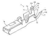
A terminal fitting in accordance with the invention is identified by the letter T in FIG. 1. The terminal T has opposite front and rear ends. A connection portion Ta extends rearward from the front end and is configured for connection with a mating male terminal fitting. A wire-fastening portion Tb extends forward from the rear end and is configured for connection with a wire W.
The wire fastening portion Tb includes an arcuate bottom wall 10 that bulges out downwardly, and first and second fastening pieces 11, 12 that extend from lateral left and right side edges of the bottom wall 10. Before crimping, the two fastening pieces 11, 12 are substantially straight and diverge obliquely upward from the bottom wall 10 to define a widened spacing toward their upper ends.
The bottom wall 10 has an upward bulging lower projection 13 formed, e.g. by cutting a portion of the bottom wall 10 and bending the cut portion up or by embossing a portion of the bottom wall 10. The lower projection 13 enhances a fastening force by biting into the bottom of the outer circumferential surface of the wire W during crimping. On the other hand, an upper projection 14 is formed near the leading end of the second fastening piece and bulges inwardly or toward the first crimping piece. The upper projection 14 is formed by embossing or by a combination of cutting and bending. The upper projection 14 is disposed on the wire fastening portion Tb at a location to hold the wire W in cooperation with the lower projection 13 and preferably the upper projection 14 bites into the upper part of the outer circumferential surface of the wire W to enhance a fastening force to the wire W in cooperation with the lower projection 13.
The second crimping piece 12 is formed with a weakened deformation-facilitating portion 15 for bending the leading edge 12A inwardly toward the first crimping piece 11 during crimping. The deformation-facilitating portion 15 is formed by partly thinning or cutting the inner side surface of the second crimping piece 12 to form a straight continuous groove 15A. The groove 15A extends substantially parallel to a line along which the second crimping piece 12 is bent and hence substantially parallel to the longitudinal direction of the wire W and substantially normal to the extending direction of the second crimping piece 12 from the bottom wall 10. The outer side surface of the second crimping piece 12 is not recessed in this embodiment. The deformation-facilitating portion 15, and specifically the groove 15A, is between the leading edge 12A than the upper projection 14 and very close to the upper projection 14.
An automated crimping apparatus includes an anvil 20 and a crimper 25, as shown in FIGS. 4-7. The anvil 20 also is called a lower mold, and is formed with an arcuate placing surface 21 that has a smaller curvature (or a larger radius of curvature) than the bottom wall 10 before crimping. The bottom surface 10 of the wire-fastening portion Tb can be placed on the placing surface 21. The crimper 25 includes left and right legs 26 that project down. The crimper 25 also includes a guide surface 27 between the upper ends of the legs 26. The guide surface 27 is arch-shaped and substantially corresponds to the arcuate shape of the bottom wall 10. Opposite lateral ends of the guide surface 27 are smoothly tangentially continuous with the inner surfaces of the legs 26. A stepped stopper 28 is formed substantially at the uppermost position of the arch-shaped guide surface 27. The guide surface 27 includes a right area 27R and a left area 27L, as shown in FIGS. 4-8. The right area 27R is disposed to the right of the stopper 28 and corresponds to the first crimping piece 11. The left area 27L is disposed to the left of the stopper 28 and corresponds to the second crimping piece 12. The guide surfaces 27R and 27L extend down from the stopper 28 and diverge away from one another toward the bottom ends of the legs 26. Accordingly, the first crimping piece 11 may approach the stopper 28 while sliding on the right area 27R of the guide surface 27 during a crimping operation, but such an approaching movement is restricted by contact of the first crimping piece 11 with the stopper 28. On the other hand, the second crimping piece 12 is permitted to enter the right area 27R after passing the stopper 28 without getting caught.
A crimping operation commences by initially placing the wire-fastening portion Tb on the placing surface 21 of the anvil 20, as shown in FIG. 4. The wire W then is supplied between the crimping pieces 11, 12 and on the bottom wall 10. The crimper 25 then is lowered toward the anvil 20 and brings the leading edges 11A, 12A of the crimping pieces 11, 12 into sliding contact with the inner surfaces of the legs 26. The crimping pieces 11, 12 then are displaced inwardly (directions toward the mating crimping pieces) by further sliding on the guide surface 27. Consequently, the first crimping piece 11 is held tense or chucked by contact between the leading edge 11A of the first crimping piece 11 and the stopper 28 (see FIG. 5). The second crimping piece 12, on the other hand, is held tense by contact between the leading edge 12A of the second crimping piece 12 and the inner side surface of a leading end portion 11B of the first crimping piece 11 (shown in phantom in FIG. 5). At this time, the crimping pieces 11, 12 are substantially straight without being curved or bent.
The crimper 25 is lowered further toward the anvil 20. The second crimping piece 12 is bent first such that its leading edge 12A is deformed inwardly substantially about the deformation-permitting portion 15, and at a position between the leading edge 12A and the upper projection 14, as shown in solid line in FIG. 5. At this time, the deformation-permitting portion 15 projects outward or is bent outwardly toward the side away from the first crimping piece 11 and closer to the left area 27L of the guide surface 27.
Subsequently, as shown in FIG. 6, the second crimping piece 12 is bent outwardly in a direction toward the left area 27L of the guide surface 27 at a position closer to the base end of the second crimping piece 12 than the upper projection. Thus, this second bending is at a location toward the bottom wall 10 and opposite from the leading edge 12A. The first crimping piece 11 also is bent outwardly toward the right area 27R of the guide surface 27 substantially at a center position of the first crimping piece 11 with respect to its extending direction or height direction. At this time, the bent portions of the crimping pieces 11,12 are in contact with the right and left areas 27R, 27L, respectively.
The above-described bending causes the leading end portion 11B of the first crimping piece 11 to be displaced sufficiently to extend substantially along the guide surface 27. This re-orientation causes the leading edge 11A of the first crimping piece 11 to move radially inward or toward the wire W (downward in FIG. 6) from the stopper 28. The first crimping piece 11 slides in contact with the left area 27L and slips between the guide surface 27 and the second crimping piece 12, as shown in FIG. 7. Accordingly, the first crimping piece 11 is curved along the guide surface 27 as a whole, and the radius of curvature of the second crimping piece 12 decreases.
A leading end 12B of the second crimping piece 12 between the leading edge 12A and the deformation-facilitating portion 15 is re-oriented to extend along the guide surface 27. This re-orientation causes the leading end 12B of the second crimping piece 12 to slide on the inner side surface of the first crimping piece 11 toward the bottom wall 10 and toward the side of the first crimping piece 11 opposite from its leading edge 11A. Accordingly, the entire second crimping piece 12 is curved along the inner circumferential surface of the first crimping piece 11 and the guide surface 27 to decrease the radius of curvature of the second crimping piece 12, as shown in FIG. 7.
The bottom wall 10 and the first and second crimping pieces 11, 12 are crimped and fastened to the outer circumferential surface of the wire W, and the upper and lower projections 14, 13 bite in the outer circumferential surface of the wire W. As a result, the wire fastening portion Tb of the terminal fitting T is crimped into connection with the wire W, as shown in FIG. 8.
In the embodiment described above, the second crimping piece 12 is thinned at a selected location along its extending direction to form the deformation-facilitating portion 15 and to ensure that the leading edge 12A deforms inwardly. Thus, the leading end 12B will not deform in a direction different from the intended direction and a crimping error resulting from such an unintended deformation is prevented.
The formation of the deformation-facilitating portion 15 between the leading edge 12A and the upper projection 14 brings about several advantages. Specifically, the second crimping piece 12 is bent at the deformation-facilitating portion 15 to incline the leading edge 12A inwardly. In this case, angles of inclination of the bent leading end 1 2B with respect to the guide surface 27 and the first crimping piece 11 are small, as compared to a case where the second crimping piece 12 is bent at a position between the bottom wall 10 and the upper projection 14. Thus, the leading end 12B that is bent at the deformation facilitating portion 15 is oriented more parallel to both the guide surface 27 and the leading end 116 of the first crimping piece 11 as compared to a bend formed between the bottom wall 10 and the upper projection 14. Thus, the second crimping piece 12 is moved smoothly along the inner side surface of the first crimping piece 11 to reduce a diameter after bending.
The deformation-facilitating portion 15 is a groove that extends substantially normal to the extension of the second crimping piece 12, i.e. along a bending line. Hence, bending can be performed more securely.
The deformation-facilitating portion 15 is a groove formed only in the inner side surface of the second crimping piece 12. Therefore, the leading end 12B of the second crimping piece 12 is bent at the deformation-facilitating portion 15 substantially about a point on the outer side surface of the second crimping piece 12 aligned with deformation facilitating portion 15. The positioning of the groove 15A in the inner side surface prevents the opening edge of the groove 15A from being caught by the inner side surface of the first crimping piece 11 and the guide surface 27 while the second crimping piece 12 is deformed to reduce a diameter as crimping progresses.
The present invention is not limited to the above-described and illustrated embodiment. For example, following embodiments also are embraced by the technical scope of the present invention as defined in the claims. Besides them, various changes can be made without departing from the scope and spirit of the present invention as defined in the claims.
Although a female terminal fitting is described in the foregoing embodiment, the present invention is applicable to male terminal fittings.
Although the second crimping piece is formed with the projections for strengthening the fastening force to the wire in the foregoing embodiment, the present invention is applicable to terminal fittings having no such projection.
Although the deformation-facilitating portion is a continuous recess in the form of a groove in the foregoing embodiment, it may be formed by a plurality of recesses discontinuously present substantially along a direction normal to the extension of the second crimping piece according to the present invention.
Although the deformation-facilitating portion is recessed only in the inner side surface of the second crimping piece in the foregoing embodiment, only the outer side surface of the second crimping piece may be recessed or both the inner and the outer side surfaces thereof may be recessed according to the present invention.
Although the deformation-facilitating portion is provided only in one position in the foregoing embodiment, it may be provided in a plurality of positions spaced apart along the extension of the second crimping piece.

Claims (8)

What is claimed is:
1. A terminal fitting having a wire-fastening portion for crimped connection to a wire, the wire fastening-portion comprising a bottom wall and first and second crimping pieces that extend from the bottom wall along extending directions, the first and second crimping pieces each having a leading end spaced from the bottom wall, the first and second crimping pieces further having inner surfaces facing one another and outer surfaces facing away from one another, a projection being formed on the inner surface of the second crimping piece and a groove extending across the inner surface of the second crimping piece substantially normal to the extending direction and at a location between the projection and the leading end of the second crimping piece, the inner surface of the first crimping piece being tapered outwardly at locations adjacent the leading end of the first crimping piece and the outer surface of the second crimping piece being tapered inwardly at locations adjacent the leading end of the second crimping piece, the outward taper on the inner surface of the first crimping piece, the inward taper on the outer surface of the second crimping piece and the groove all facilitating inward bending of the second crimping piece between the leading end and the projection.
2. A terminal fitting according to claim 1, wherein the projection is configured to bite in the outer circumferential surface of the wire when the wire-fastening portion is crimped into connection with the wire.
3. A terminal fitting according to claim 1, wherein the groove is formed only on the inner side surface of the second crimping piece.
4. A terminal fitting according to claim 1, wherein the groove is formed by thinning the second crimping piece.
5. A terminal fitting according to claim 1, wherein the bottom wall is formed with at least one bottom projection for biting into the wire.
6. A terminal fitting according to claim 1, wherein the first and second crimping pieces extend substantially equal distances from the bottom wall.
7. A terminal fitting according to claim 1, wherein the projection on the inner surface of the second crimping piece abuts the groove extending across the inner surface of the second crimping piece.
8. A terminal fitting according to claim 7, wherein the taper on the outer surface of the second crimping piece extends a selected distance from the leading end of the second crimping piece, the groove on the second crimping piece being spaced from the leading end of the second crimping piece a distance greater than the selected distance for the taper.
US09/776,338 2000-02-02 2001-02-02 Terminal fitting Expired - Fee Related US6468116B2 (en)

Applications Claiming Priority (3)

Application Number Priority Date Filing Date Title
JPJP2000-025482 2000-02-02
JP2000025482A JP2001217013A (en) 2000-02-02 2000-02-02 Terminal fitting
JP2000-025482 2000-02-02

Publications (2)

Publication Number Publication Date
US20010016460A1 US20010016460A1 (en) 2001-08-23
US6468116B2 true US6468116B2 (en) 2002-10-22

Family

ID=18551337

Family Applications (1)

Application Number Title Priority Date Filing Date
US09/776,338 Expired - Fee Related US6468116B2 (en) 2000-02-02 2001-02-02 Terminal fitting

Country Status (4)

Country Link
US (1) US6468116B2 (en)
EP (1) EP1122819B1 (en)
JP (1) JP2001217013A (en)
DE (1) DE60100340T2 (en)

Cited By (11)

* Cited by examiner, † Cited by third party
Publication number Priority date Publication date Assignee Title
US20060003641A1 (en) * 2004-01-07 2006-01-05 Sumitomo Wiring Systems, Ltd. Terminal fitting
US20060121797A1 (en) * 2002-08-27 2006-06-08 Claude Casses Electrical contact terminal comprising an elastic contact blade
US20070149068A1 (en) * 2005-12-26 2007-06-28 Sumitomo Wiring Systems, Ltd. Terminal fitting
US20120214361A1 (en) * 2009-10-28 2012-08-23 Yazaki Corporation Press bond terminal
US20130213710A1 (en) * 2010-10-14 2013-08-22 Yazaki Corporation Water Proof Crimping Terminal and Crimping Method of Water Proof Crimping Terminal
US20130330987A1 (en) * 2012-06-07 2013-12-12 Sumitomo Wiring Systems, Ltd. Crimp terminal
US20150072573A1 (en) * 2013-02-21 2015-03-12 Furukawa Electric Co.,Ltd. Crimp terminal, cable with terminal, and cable harness structure
US9853367B2 (en) * 2013-11-01 2017-12-26 Furukawa Electric Co., Ltd. Wire harness, method of connecting terminal and coated wire, and mold
US11094432B2 (en) * 2019-09-24 2021-08-17 Sumitomo Wiring Systems, Ltd. Communication cable and crimping member
US20230058367A1 (en) * 2021-08-18 2023-02-23 Royal Precision Products, Llc Electrical busbar and method of fabricating the same
US20230154644A1 (en) * 2019-09-09 2023-05-18 Eaton Intelligent Power Limited Electrical busbar and method of fabricating the same

Families Citing this family (21)

* Cited by examiner, † Cited by third party
Publication number Priority date Publication date Assignee Title
FR2858118A1 (en) * 2003-07-25 2005-01-28 Framatome Connectors Int Electric crimp contact unit for motor vehicle air bag device, has crimping core having blades and deformable zones for surrounding electrical wire, and tab placed in crimping zone such that tab applies pressure on wire
FR2877150B1 (en) * 2004-10-27 2007-01-19 Radiall Sa METHOD FOR MOUNTING AN ELECTRICAL CONNECTOR ON A COAXIAL CABLE, AND SUCH A CONNECTOR
JP4834605B2 (en) * 2007-05-15 2011-12-14 株式会社オートネットワーク技術研究所 Outer conductor terminal
US7803008B2 (en) * 2007-11-27 2010-09-28 Yazaki Corporation Press-clamping structure and press-clamping terminal
JP5105521B2 (en) * 2007-11-27 2012-12-26 矢崎総業株式会社 Crimping structure of crimping terminal to electric wire
JP5146187B2 (en) * 2008-08-06 2013-02-20 住友電装株式会社 Terminal fitting and wire harness
USD621368S1 (en) * 2009-05-19 2010-08-10 Tyco Electronics Amp Korea Ltd. Fuse terminal
JP5506028B2 (en) * 2009-09-24 2014-05-28 矢崎総業株式会社 Crimping device
JP2011103262A (en) * 2009-11-12 2011-05-26 Yazaki Corp Crimping terminal and method for crimping terminal
JP2012186115A (en) * 2011-03-08 2012-09-27 Yazaki Corp Connector
WO2013058015A1 (en) * 2011-10-19 2013-04-25 株式会社村田製作所 Coaxial connector
CN102709717A (en) * 2012-01-13 2012-10-03 加炜电子(昆山)有限公司 Single-core-wire connector terminal
JP2013149564A (en) * 2012-01-23 2013-08-01 Auto Network Gijutsu Kenkyusho:Kk Terminal fitting
JP2013182727A (en) * 2012-02-29 2013-09-12 Yazaki Corp Terminal fitting
JP6074336B2 (en) 2013-08-06 2017-02-01 日新製鋼株式会社 Aluminum wire connection structure
JP6402930B2 (en) * 2015-03-06 2018-10-10 株式会社オートネットワーク技術研究所 Terminal and electric wire with terminal
JP6423333B2 (en) 2015-12-16 2018-11-14 矢崎総業株式会社 Crimp terminal and electric wire with terminal
JP6806613B2 (en) * 2017-03-30 2021-01-06 矢崎総業株式会社 Crimping terminal
JP2018200835A (en) * 2017-05-29 2018-12-20 矢崎総業株式会社 Electric wire with terminal
JP1599728S (en) * 2017-07-07 2018-03-19
CN215983356U (en) * 2021-08-31 2022-03-08 浙江盾安人工环境股份有限公司 Electronic expansion valve

Citations (7)

* Cited by examiner, † Cited by third party
Publication number Priority date Publication date Assignee Title
US3781459A (en) 1972-07-20 1973-12-25 Anderson Electric Corp Compression connector for electrical conductors
GB1435011A (en) 1973-02-21 1976-05-12 Post Office Criping clips
US3989339A (en) 1975-10-02 1976-11-02 Thomas & Betts Corporation Electrical connector and method of making same
JPH04209471A (en) 1990-11-30 1992-07-30 Sumitomo Wiring Syst Ltd Crimp contact
US5561267A (en) * 1993-11-30 1996-10-01 Sumitomo Wiring Systems, Ltd. Crimp terminal and process for producing the same
US5635676A (en) 1992-12-09 1997-06-03 Thomas & Betts Corporation Compression connectors
US6206727B1 (en) * 1998-11-27 2001-03-27 Sumitomo Wiring Systems, Ltd. Terminal and crimping method

Patent Citations (7)

* Cited by examiner, † Cited by third party
Publication number Priority date Publication date Assignee Title
US3781459A (en) 1972-07-20 1973-12-25 Anderson Electric Corp Compression connector for electrical conductors
GB1435011A (en) 1973-02-21 1976-05-12 Post Office Criping clips
US3989339A (en) 1975-10-02 1976-11-02 Thomas & Betts Corporation Electrical connector and method of making same
JPH04209471A (en) 1990-11-30 1992-07-30 Sumitomo Wiring Syst Ltd Crimp contact
US5635676A (en) 1992-12-09 1997-06-03 Thomas & Betts Corporation Compression connectors
US5561267A (en) * 1993-11-30 1996-10-01 Sumitomo Wiring Systems, Ltd. Crimp terminal and process for producing the same
US6206727B1 (en) * 1998-11-27 2001-03-27 Sumitomo Wiring Systems, Ltd. Terminal and crimping method

Cited By (21)

* Cited by examiner, † Cited by third party
Publication number Priority date Publication date Assignee Title
US20060121797A1 (en) * 2002-08-27 2006-06-08 Claude Casses Electrical contact terminal comprising an elastic contact blade
US7140927B2 (en) * 2002-08-27 2006-11-28 Fci Electrical contact terminal comprising an elastic contact blade
US20060003641A1 (en) * 2004-01-07 2006-01-05 Sumitomo Wiring Systems, Ltd. Terminal fitting
US7090545B2 (en) * 2004-01-07 2006-08-15 Sumitomo Wiring Systems, Ltd. Terminal fitting
US20070149068A1 (en) * 2005-12-26 2007-06-28 Sumitomo Wiring Systems, Ltd. Terminal fitting
US7347747B2 (en) * 2005-12-26 2008-03-25 Sumitomo Wiring Systems, Ltd Terminal fitting with a resilient reinforcing piece
US20120214361A1 (en) * 2009-10-28 2012-08-23 Yazaki Corporation Press bond terminal
US9054431B2 (en) * 2009-10-28 2015-06-09 Yazaki Corporation Press bond terminal
US20130213710A1 (en) * 2010-10-14 2013-08-22 Yazaki Corporation Water Proof Crimping Terminal and Crimping Method of Water Proof Crimping Terminal
US9065189B2 (en) * 2010-10-14 2015-06-23 Yazaki Corporation Water proof crimping terminal and crimping method of water proof crimping terminal
US9022819B2 (en) * 2012-06-07 2015-05-05 Sumitomo Wiring Systems, Ltd. Crimp terminal
US20130330987A1 (en) * 2012-06-07 2013-12-12 Sumitomo Wiring Systems, Ltd. Crimp terminal
US20150072573A1 (en) * 2013-02-21 2015-03-12 Furukawa Electric Co.,Ltd. Crimp terminal, cable with terminal, and cable harness structure
US9853367B2 (en) * 2013-11-01 2017-12-26 Furukawa Electric Co., Ltd. Wire harness, method of connecting terminal and coated wire, and mold
US20230154644A1 (en) * 2019-09-09 2023-05-18 Eaton Intelligent Power Limited Electrical busbar and method of fabricating the same
US11862358B2 (en) * 2019-09-09 2024-01-02 Eaton Intelligent Power Limited Electrical busbar and method of fabricating the same
US20240177885A1 (en) * 2019-09-09 2024-05-30 Eaton Intelligent Power Limited Electrical busbar and method of fabricating the same
US12191054B2 (en) * 2019-09-09 2025-01-07 Eaton Intelligent Power Limited Electrical busbar and method of fabricating the same
US11094432B2 (en) * 2019-09-24 2021-08-17 Sumitomo Wiring Systems, Ltd. Communication cable and crimping member
US20230058367A1 (en) * 2021-08-18 2023-02-23 Royal Precision Products, Llc Electrical busbar and method of fabricating the same
US12136500B2 (en) * 2021-08-18 2024-11-05 Eaton Intelligent Power Limited Electrical busbar and method of fabricating the same

Also Published As

Publication number Publication date
JP2001217013A (en) 2001-08-10
EP1122819A1 (en) 2001-08-08
US20010016460A1 (en) 2001-08-23
DE60100340T2 (en) 2004-04-29
EP1122819B1 (en) 2003-06-11
DE60100340D1 (en) 2003-07-17

Similar Documents

Publication Publication Date Title
US6468116B2 (en) Terminal fitting
US5427552A (en) Electrical terminal and method of fabricating same
US8152576B2 (en) Female terminal fitting
EP2244334A1 (en) Terminal fitting and method of forming it
EP1369959B1 (en) A connector, a disengagement jig and a method
US5545062A (en) Terminal for passing through waterproof rubber plug and method of producing terminal
EP1689037A1 (en) A terminal fitting and method of forming it
EP1094572A1 (en) A terminal fitting and a connector
US9843120B2 (en) Terminal metal fitting
US8454394B2 (en) Terminal fitting having an auxilary resilient piece
EP2375512A1 (en) Terminal fitting and production method therefor
EP1378968A1 (en) A connector
CN1815816B (en) A terminal fitting, connector provided therewith and method of forming a terminal fitting
US10919079B2 (en) Method of manufacturing band-shaped metal wire member including bonded portion
EP1261075B1 (en) A watertight connector and a method for mounting it
JP2003297490A (en) Connector
EP1742300B1 (en) A terminal fitting and a forming method therefor
JPH0742050U (en) Branch connection connector
US6261134B1 (en) One-piece hooded socket contact and method of producing same
US12149036B2 (en) Terminal and terminal wire assembly
EP1689038B1 (en) A terminal fitting, a connector provided therewith, a method of forming a terminal fitting and an electrical connection testing method
EP1689036B1 (en) A terminal fitting, a connector provided therewith and a method of forming a terminal fitting
GB2056609A (en) Blind fastener and method of manufacture thereof
EP1601061B1 (en) A terminal and a method of forming it
EP1560297A1 (en) Connector with retaining finger having excessive deformation prevention means

Legal Events

Date Code Title Description
AS Assignment

Owner name: SUMITOMO WIRING SYSTEMS, LTD., JAPAN

Free format text: ASSIGNMENT OF ASSIGNORS INTEREST;ASSIGNOR:KOIDE, TAKASHI;REEL/FRAME:011661/0479

Effective date: 20010228

FEPP Fee payment procedure

Free format text: PAYOR NUMBER ASSIGNED (ORIGINAL EVENT CODE: ASPN); ENTITY STATUS OF PATENT OWNER: LARGE ENTITY

FPAY Fee payment

Year of fee payment: 4

FPAY Fee payment

Year of fee payment: 8

REMI Maintenance fee reminder mailed
LAPS Lapse for failure to pay maintenance fees
STCH Information on status: patent discontinuation

Free format text: PATENT EXPIRED DUE TO NONPAYMENT OF MAINTENANCE FEES UNDER 37 CFR 1.362

STCH Information on status: patent discontinuation

Free format text: PATENT EXPIRED DUE TO NONPAYMENT OF MAINTENANCE FEES UNDER 37 CFR 1.362

FP Lapsed due to failure to pay maintenance fee

Effective date: 20141022