US6467526B1 - Method of making a jewelry ring in a vertical mold - Google Patents

Method of making a jewelry ring in a vertical mold Download PDF

Info

Publication number
US6467526B1
US6467526B1 US09/694,723 US69472300A US6467526B1 US 6467526 B1 US6467526 B1 US 6467526B1 US 69472300 A US69472300 A US 69472300A US 6467526 B1 US6467526 B1 US 6467526B1
Authority
US
United States
Prior art keywords
ring
piece
mold
replica
piece plug
Prior art date
Legal status (The legal status is an assumption and is not a legal conclusion. Google has not performed a legal analysis and makes no representation as to the accuracy of the status listed.)
Expired - Lifetime
Application number
US09/694,723
Inventor
Steven Cope
Current Assignee (The listed assignees may be inaccurate. Google has not performed a legal analysis and makes no representation or warranty as to the accuracy of the list.)
Quality Gold Inc
Original Assignee
I B Goodman Manufacturing Co Inc
Priority date (The priority date is an assumption and is not a legal conclusion. Google has not performed a legal analysis and makes no representation as to the accuracy of the date listed.)
Filing date
Publication date
Application filed by I B Goodman Manufacturing Co Inc filed Critical I B Goodman Manufacturing Co Inc
Priority to US09/694,723 priority Critical patent/US6467526B1/en
Assigned to I.B. GOODMAN MANUFACTURING CO., INC. reassignment I.B. GOODMAN MANUFACTURING CO., INC. ASSIGNMENT OF ASSIGNORS INTEREST (SEE DOCUMENT FOR DETAILS). Assignors: COPE, STEVEN
Application granted granted Critical
Publication of US6467526B1 publication Critical patent/US6467526B1/en
Anticipated expiration legal-status Critical
Assigned to QUALITY GOLD, INC. reassignment QUALITY GOLD, INC. ASSIGNMENT OF ASSIGNORS INTEREST (SEE DOCUMENT FOR DETAILS). Assignors: I.B. GOODMAN MANUFACTURING CO., INC.
Expired - Lifetime legal-status Critical Current

Links

Images

Classifications

    • BPERFORMING OPERATIONS; TRANSPORTING
    • B22CASTING; POWDER METALLURGY
    • B22CFOUNDRY MOULDING
    • B22C9/00Moulds or cores; Moulding processes
    • B22C9/22Moulds for peculiarly-shaped castings
    • B22C9/24Moulds for peculiarly-shaped castings for hollow articles
    • BPERFORMING OPERATIONS; TRANSPORTING
    • B22CASTING; POWDER METALLURGY
    • B22CFOUNDRY MOULDING
    • B22C7/00Patterns; Manufacture thereof so far as not provided for in other classes
    • B22C7/02Lost patterns
    • BPERFORMING OPERATIONS; TRANSPORTING
    • B22CASTING; POWDER METALLURGY
    • B22CFOUNDRY MOULDING
    • B22C9/00Moulds or cores; Moulding processes
    • B22C9/02Sand moulds or like moulds for shaped castings
    • B22C9/04Use of lost patterns
    • BPERFORMING OPERATIONS; TRANSPORTING
    • B22CASTING; POWDER METALLURGY
    • B22DCASTING OF METALS; CASTING OF OTHER SUBSTANCES BY THE SAME PROCESSES OR DEVICES
    • B22D25/00Special casting characterised by the nature of the product
    • B22D25/02Special casting characterised by the nature of the product by its peculiarity of shape; of works of art
    • B22D25/026Casting jewelry articles

Definitions

  • the present invention relates to a method of producing a jewelry ring or a portion of a jewelry ring. More particularly, the present invention relates to a method of molding a jewelry ring or a portion of a jewelry ring with a hollow portion and a beveled or rounded inner diameter on the shank of the ring.
  • the ring replica having an inner diameter of the shank that is “flat,” is subsequently slidably removed from the cylindrical plug.
  • Such vertical molds with the cylindrical plug are not capable of forming a ring with a beveled or rounded inner diameter on the shank.
  • a horizontal two-part mold used to form a plastiwax replica of a ring.
  • a horizontal two-part mold is oriented with the lower die and the upper die arranged to define a cavity having the circular shape of the ring; each die is formed with a cavity defining substantially one-half the ring shape in an axial direction.
  • Investment casting is subsequently used to convert the plastiwax replica into a metal ring.
  • a horizontally oriented mold configuration is utilized in this method because, according to the four Baum patents, “using the conventional techniques and the vertically oriented mold configuration, it is impossible to produce a ring having an inner round radius design.” See, e.g., U.S. Pat. No. 5,916,271 Col. 5, Lines 5-10.
  • a horizontal mold has drawbacks. Due to the imperfect mating characteristics and shrinkage of the hardened material, a mold seam is inevitable in molds using two or more parts for defining an inner cavity. In utilizing a horizontal mold to achieve a beveled or rounded inside diameter on the shank, a seam will be produced along the entire inner and outer circumference of the ring. Removal of such a lengthy seam involves excess time and loss of excess material. Furthermore, horizontal molds cannot be used to produce rings with certain design features. In contrast, the present invention provides for a shorter seam line at only two places around the circumference of the ring.
  • the hollow wax replica ring used for the lost-wax casting is formed by molding plastiwax around a water soluble wax core insert in a vertical metal mold.
  • the vertical mold is closed around a cylindrical core or mandrel.
  • the wax core insert is generally arcuate in shape and has a respective spacer pin extending radially inwardly from each end of the arcuate core insert.
  • the arcuate extent of the arcuate core insert is substantially 130°.
  • the cylindrical mandrel is formed of two pieces which are locked together to form the mandrel while defining a receptacle to accommodate the alignment peg of the wax core.
  • the core insert is dissolved to yield a hollow space within the replica.
  • the hollow wax replica is then used for a conventional lost-wax (investment) casting step.
  • the prior art ring has an inner (finger-facing) surface that was cylindrical. That is, the prior art ring has a ‘flat’ inner radius design.
  • the invention provides a method of producing a jewelry ring with a hollow portion comprising the steps of providing a vertical mold comprising an upper mold half and lower mold half; providing a multi-piece plug comprising at least a first piece and a second piece; providing a soluble insert; positioning said soluble insert and said multi-piece plug within said vertical mold so as to form a mold cavity; introducing molten material into said mold cavity; cooling said molten material to form a ring replica; separating the upper mold half and lower mold half; removing the multi-piece plug with said ring replica formed around it from within the upper mold half or lower mold half; separating said first piece of said multi-piece plug from said second piece and thereby releasing said ring replica from said multi-piece plug; dissolving the insert from said ring replica; casting a jewelry ring using said ring replica in an investment casting process.
  • the invention further provides a method of producing a ring replica comprising the steps of providing a vertical mold comprising an upper mold half and a lower mold half; providing a multi-piece plug comprising at least a first piece and a second piece; providing a soluble insert; positioning said soluble insert and said multi-piece plug within said vertical mold so as to form a mold cavity; introducing molten material into said mold cavity; cooling said molten material to form a ring replica; separating the upper mold half from the lower mold half; removing said multi-piece plug with said ring replica formed around it from the upper mold half or lower mold half, and separating said first piece of said multi-piece plug from said second piece thereby releasing said ring replica from said multi-piece plug.
  • FIG. 1 a is a plan view of the two halves of a vertical mold.
  • FIG. 1 b is a perspective exploded view of the half of the vertical mold with a multi-piece plug.
  • FIG. 1 c is another perspective exploded view of the half of the vertical mold with a multi-piece plug.
  • FIG. 2 a is a perspective view of the multi-piece plug.
  • FIG. 2 b is a perspective view of the multi-piece plug with a soluble insert and a ring replica.
  • FIG. 2 c is another perspective view of the multi-piece plug with the soluble insert and the ring replica.
  • FIG. 3 is a perspective view of the insert mold.
  • FIG. 4 is a perspective view of the soluble insert.
  • FIG. 5 is a perspective view of the one half of the vertical mold, the multi-piece plug and the soluble insert as assembled.
  • FIG. 6 is a perspective view of a ring replica with the soluble insert.
  • FIG. 7 is a perspective view of the ring replica after removal of the soluble insert.
  • FIG. 8 is a plan view of the ring replica.
  • FIGS. 9A and 9B are perspective views of the facing mold half and backing old half used to form the setting.
  • FIG. 10 is a perspective view of the setting.
  • FIG. 11 is a perspective view of a metal ring with an attached metal setting.
  • FIG. 12 is a cross-sectional view of the ring shown in FIG. 11, taken along line 12 — 12 .
  • inventive method described hereinafter pertains to the production of a metal jewelry ring
  • inventive method may be applied to produce a variety of articles and designs, using an array of manufacturing techniques and materials.
  • the preferred method for achieving the inventive method is described as such for illustrative purposes only.
  • a jewelry ring is capable of existing in a variety of forms and being used in numerous applications.
  • a jewelry ring is generally circular and may be accompanied and attached with additional pieces, such as settings and/or precious stones.
  • a jewelry ring is typically worn on a finger but given contemporary and evolving applications of jewelry rings, as defined herein, it can also be worn as a toe ring or used as an attachment to an ear or nose.
  • a vertical mold is utilized to produce a jewelry ring 10 having a hollow portion and a beveled or rounded inner diameter on the shank 12 such as that shown in FIG. 11 and FIG. 12, wherein the inner diameter of the ring is of varying dimensions.
  • the interior shape of a ring having such design is obtusely angled or generally parabolic.
  • a vertically oriented mold configuration is utilized. As shown in FIGS. 1A-C, and 5 the ring mold 20 is oriented with the lower mold half 22 , upper mold half 24 , and a multi-piece plug 50 arranged to define a mold cavity 28 having the shape of the desired ring replica. Each mold half 22 and 24 , in conjunction with the multi-piece plug 50 , forms a mold cavity 28 defining substantially one-half the ring replica 40 in the radial direction, illustrated by a dashed line in FIG. 11 .
  • the plug 50 is a multi-piece plug consisting of at least two pieces 52 , 54 .
  • the at least two pieces 52 , 54 Prior to being placed within the mold halves, 22 , 24 , or upon being placed within the mold halves 22 , 24 , the at least two pieces 52 , 54 are connected together to form a substantially continuous plug 50 , but the at least two pieces 52 , 54 remain separable.
  • a portion 56 of the multi-piece plug is inwardly angled or curved, i.e., it has a varying outer diameter or cross-sectional area so as to form the beveled or rounded inner diameter on the shank 12 of the ring.
  • the multi-piece plug 50 preferably includes at least one locator pin 58 that locates the plug 50 in one of the mold halves 22 , 24 , of the vertical mold 20 .
  • at least one piece 52 or 54 of the multi-piece plug 50 includes at least one locking means 60 that holds at least the first piece 52 and the second piece 54 of the multi-piece plug 50 together in the proper orientation. It is believed that this locking means 60 relieves stress on the soluble insert 30 preventing cracking of the soluble insert 30 during the introduction of the molten material into the mold cavity 28 .
  • the mold halves 22 , 24 , and the multi-piece plug 50 may be produced by a variety of methods. For example, conventional tooling may be utilized to shape the mold halves 22 , 24 , and multi-piece plug 50 to form the desired mold cavity 28 . Other methods include casting, hand machining, and the use of resins which can be molded to the desired shape. Each of the mold halves 22 , 24 , and the multi-piece plug 50 can be made by the same method or each part can be made by a different method. As will be appreciated by those of ordinary skill in the art, the desired shape and size of the mold halves 22 , 24 and multi-piece plug 50 should allow for shrinkage of a molten material, such as wax or plastic, as it solidifies within the mold cavity 28 .
  • a molten material such as wax or plastic
  • the mold halves 22 , 24 and multi-piece plug 50 should be constructed of material capable of containing molten material such as wax or plastic without deformation, and of forming said molten material in sufficient detail to produce the desired ring design.
  • the mold halves 22 , 24 and multi-piece plug 50 may therefore be formed of brass, other metals, resins, or any materials capable of withstanding the temperature, thermal stresses, and pressure associated with the ring replica molding process.
  • such material should have adequate heat transfer capabilities for proper and rapid cooling of the molten material.
  • the mold halves have sufficient strength that they require no additional support, such as a mold box, to withstand the molding pressures.
  • the ring mold 20 is used in conjunction with a soluble insert 30 to produce a ring replica 40 of a hollow or partially hollow construction.
  • a soluble insert 30 is an insert made of a material that is soluble in one or more solvents.
  • a material that is soluble in one or more solvents For example, water soluble waxes are well known and used in the industry. Ceramics soluble in acidic solutions are well known and used in the jewelry industry.
  • a soluble insert 30 is positioned within mold half 22 or 24 , prior to introduction of the molten material. See FIG. 5 .
  • the soluble insert 30 may be positioned anywhere within the mold cavity and may be secured by alignment means, such as alignment bars 64 which correspond with grooves 66 formed within the multi-piece plug 50 .
  • the soluble insert 30 may be positioned by other methods known in the art such as pegs or stops.
  • Such alignment means serve to maintain the position and stability of the soluble insert 30 during injection of the molten material into the mold cavity 28 . In addition, they provide for better airflow within the mold 20 , reducing flashing problems that may occur during formation of the ring replica 40 .
  • such soluble insert 30 is positioned within the crown portion 68 of the mold cavity 28 .
  • the soluble insert 30 may be produced by utilizing an insert mold 70 , as shown in FIG. 3 .
  • Such an insert mold 70 comprises at least an upper and lower mold half formed with a cavity 76 in the shape of the desired soluble insert 30 .
  • the insert mold 70 can be formed so as to form alignment means, for example, at least one alignment bar 64 .
  • the alignment bar 64 may be configured so that the soluble insert 30 can be held in position by the multi-piece plug 50 .
  • the alignment bar 64 also provides a means to collect any gases trapped within the insert mold 70 , thereby ensuring proper filling of the soluble insert 30 without air pockets.
  • the soluble insert 30 will be of a shape generally similar to that of the crown portion 68 of the ring, but slightly reduced in size so as to allow molten material to flow around the shape of the soluble insert 30 to form the outer wall of the ring 10 .
  • Methods of producing soluble inserts 30 are known in the art. For example, see Japanese Laid Open Patent Application 2-232002, filed Mar. 7, 1989 which is incorporated herein by reference. It is conceivable that other processes, such as machining, may be used to produce the soluble insert 30 .
  • the soluble insert 30 can be formed so as to include a top cap 80 .
  • the top cap 80 allows the top of the crown portion 68 of the ring replica 40 to be formed within the vertical mold 20 , without the use of an additional die insert. In this way, one vertical mold 20 can be used to form more than one ring replica design.
  • the top cap 80 is shaped to include the features desired in the crown portion 68 of the ring replica 40 . When the molten material is introduced into the mold cavity, it flows around the top cap 80 , giving the desired shape to the ring replica 40 .
  • Molten material is introduced into the mold cavity 28 .
  • Equipment suitable for adequately melting such molten material prior to introduction into the mold cavity 28 is well known and commercially available.
  • introduction of said molten material into the mold cavity 28 should be conducted in a manner which facilitates the escape of all excess air or gases from within the mold cavity 28 .
  • Such methods are well known to those of ordinary skill in the art.
  • a “wax pot” subject to adequate pressure and heat may be used to melt and inject the molten material into the mold cavity 28 .
  • the ring replica 40 is removed from the return mold 20 .
  • the multi-piece plug 50 can be equipped with handles 82 .
  • the handles 82 allow the ring replica 40 and the multi-piece plug 50 to be removed from the mold halves 22 , 24 more easily and without damaging the ring replica 40 .
  • the multi-piece plug 50 may consist of more than two pieces. In such case, the plug would be similarly separated into its individual pieces to release the ring replica.
  • the ring replica 40 after removal from the multi-piece plug 50 contains the soluble insert defining the desired hollow portion of the ring body.
  • the soluble insert 30 being soluble, is then removed from the ring replica 40 by exposure of the ring replica 40 to the proper solution, in a manner well known in the art, resulting in a ring replica 40 of a hollow or partially hollow construction. See FIG. 7 .
  • the hollow portion 90 can have an arcuate length greater than 180°. The hollow portion 90 extends from one side of the alignment bar 64 to the other side. See FIG. 6 .
  • the ring replica 40 made by the process of the present invention can be used to produce a metal ring by the lost wax casting method which is well known in the art.
  • ring replicas 40 are placed on a wax pole to form a “tree,” which is subsequently encased in a cylinder of investment material.
  • Plaster-of-Paris containing gypsum and silica, is typically used as the investment material.
  • Investment materials are well-known in the art and any suitable investment material may be used with the ring replica of the present invention.
  • the investment material may be placed under a vacuum to remove air from the material.
  • the cylinder of investment material is subsequently dewaxed i.e., the ring replica is melted and/or baked out of the investment material.
  • the baked investment material then defines an investment mold cavity in the shape of the original wax tree.
  • molten metal such as gold, platinum, or any desired metal
  • the investment material may be removed from the tree by various means, such as pressurized water removal.
  • the cast metal rings or ring portions formed are removed from the tree, for example by clipping.
  • the metal rings may then be polished and finished.
  • a metal setting 100 may be attached to the finished metal ring 10 .
  • a setting 100 is shown in FIG. 11 and is formed by utilizing backing and facing mold halves 120 , 122 such as that shown in FIG. 9 .
  • a setting replica 130 is formed within the backing and facing mold halves 120 , 122 .
  • Such a setting replica 130 is generally formed of plastiwax, although any suitable wax or plastic known in art the can be used.
  • metal settings are formed in a lost wax investment casting process similar to that described above for making metal rings or ring portions.
  • the multi-piece plug 50 may consist of more than two pieces. In such case, the multi-piece plug 50 would be separated into its individual pieces to release the ring replica 40 .

Landscapes

  • Engineering & Computer Science (AREA)
  • Mechanical Engineering (AREA)
  • Molds, Cores, And Manufacturing Methods Thereof (AREA)

Abstract

A method of molding a jewelry ring having a beveled or rounded inner diameter and a hollow portion in a vertical mold comprises utilizing a multi-piece plug and a soluble insert in a mold to define a mold cavity in the desired shape of the ring or a portion of the ring. A molten material is introduced into the mold cavity and upon hardening forms a ring replica which is removed from the mold by first removing the formed ring replica from the mold halves and then removing the ring replica from the multi-piece plug by separating the multi-piece plug into its individual pieces. The ring replica can be used to form jewelry rings by investment casting.

Description

FIELD OF THE INVENTION
The present invention relates to a method of producing a jewelry ring or a portion of a jewelry ring. More particularly, the present invention relates to a method of molding a jewelry ring or a portion of a jewelry ring with a hollow portion and a beveled or rounded inner diameter on the shank of the ring.
BACKGROUND INFORMATION
In the art of jewelry making, various manufacturing processes are utilized to produce mass quantities of metallic jewelry articles in intricate detail: electroforming, die striking, and casting, for example. These processes facilitate high volume production at relatively low production cost. However, jewelry makers continue to seek innovative methods that reduce production costs even further while maintaining the ability to produce high quality articles with sufficient detail and comfort for the wearer.
Because jewelry making is an industry that relies heavily on precious metals, raw materials constitute a significant portion of the production costs. Methods that maximize the efficiency of materials usage in production are highly valued. It is well known in the art that producing jewelry articles of hollow or partially hollow construction may minimize such costs. In addition, processes that reduce the need to grind away material, such as seam lines that result from molding, minimize excess use of materials and time.
In addition to being mindful of the high production costs in jewelry making, jewelry ring makers recognize the importance of comfort in their designs. To achieve a more comfortable design, the prior art teaches methods by which jewelry rings can be manufactured with a shank that is beveled or rounded on the inside diameter of the shank i.e., that portion of the shank that contacts the finger. The shank of a ring is defined as the portion of the ring that encircles the finger. A beveled or rounded inside diameter provides improved comfort in the wearing, placement, and removal of the ring. In the art of jewelry ring making, prior to the present invention, there had been distinct lack of knowledge as to how to manufacture jewelry rings with a hollow portion and a beveled or rounded inside diameter on the shank in a vertical mold.
As shown in U.S. Pat. No. 3,838,728, “Method for Molding Finger Rings,” issued to Voegele on Oct. 1, 1974, and U.S. Pat. No. 3,511,466, “Mold for Wax Patterns for Casting Finger Rings,” issued on May 12, 1970 to Kaplan, conventional vertical molds used to mold ring replicas utilize upper and lower mold halves and a one-piece cylindrical plug to form a mold cavity in the shape of a ring. The upper and lower mold halves form the upper and lower halves of the circumference of the ring, respectively and hold the cylindrical plug in place to form a mold cavity. Once formed in the mold cavity, the ring replica and cylindrical plug are removed from the mold halves. The ring replica, having an inner diameter of the shank that is “flat,” is subsequently slidably removed from the cylindrical plug. Such vertical molds with the cylindrical plug are not capable of forming a ring with a beveled or rounded inner diameter on the shank.
One method of producing jewelry rings with an inner round radius design on the shank is disclosed in U.S. Pat. No. 6,032,719, “Method for Producing Hollow Jewelry Ring,” issued to Baum on Mar. 7, 2000; U.S. Pat. No. 5,916,271, “Hollow Jewelry Ring Having Inner Round Design,” issued to Baum on Jun. 29, 1999; U.S. Pat. No. 5,718,278, “Method for Producing Hollow Ring Having Inner Round Radius Design,” issued to Baum on Feb. 17, 1998; and U.S. Pat. No. 5,979,537, “Wax Replica and Soluble Core Insert Used for Producing Hollow Jewelry Ring,” issued to Baum on Nov. 9, 1999. These four patents disclose a horizontal two-part mold used to form a plastiwax replica of a ring. A horizontal two-part mold is oriented with the lower die and the upper die arranged to define a cavity having the circular shape of the ring; each die is formed with a cavity defining substantially one-half the ring shape in an axial direction. Investment casting is subsequently used to convert the plastiwax replica into a metal ring. A horizontally oriented mold configuration is utilized in this method because, according to the four Baum patents, “using the conventional techniques and the vertically oriented mold configuration, it is impossible to produce a ring having an inner round radius design.” See, e.g., U.S. Pat. No. 5,916,271 Col. 5, Lines 5-10.
The use of a horizontal mold has drawbacks. Due to the imperfect mating characteristics and shrinkage of the hardened material, a mold seam is inevitable in molds using two or more parts for defining an inner cavity. In utilizing a horizontal mold to achieve a beveled or rounded inside diameter on the shank, a seam will be produced along the entire inner and outer circumference of the ring. Removal of such a lengthy seam involves excess time and loss of excess material. Furthermore, horizontal molds cannot be used to produce rings with certain design features. In contrast, the present invention provides for a shorter seam line at only two places around the circumference of the ring.
It is known in the art to use a vertical mold with a multi-piece plug to form a ring of solid construction, i.e., no hollow portion, with a rounded or beveled inside diameter.
It is also known in the art to manufacture a hollow jewelry ring using a lost-wax casting process. The hollow wax replica ring used for the lost-wax casting is formed by molding plastiwax around a water soluble wax core insert in a vertical metal mold. The vertical mold is closed around a cylindrical core or mandrel. The wax core insert is generally arcuate in shape and has a respective spacer pin extending radially inwardly from each end of the arcuate core insert. The arcuate extent of the arcuate core insert is substantially 130°. A sprue terminating with an alignment peg extended radially inwardly from a central part of the arcuate core insert. The cylindrical mandrel is formed of two pieces which are locked together to form the mandrel while defining a receptacle to accommodate the alignment peg of the wax core. After the wax replica is formed around the core insert, the core insert is dissolved to yield a hollow space within the replica. The hollow wax replica is then used for a conventional lost-wax (investment) casting step. The prior art ring has an inner (finger-facing) surface that was cylindrical. That is, the prior art ring has a ‘flat’ inner radius design.
However, previously there has been no method of producing a ring with a hollow portion made using a soluble insert and a rounded or beveled inside diameter on the shank made using a multi-piece plug in a vertical mold.
SUMMARY OF THE INVENTION
The invention provides a method of producing a jewelry ring with a hollow portion comprising the steps of providing a vertical mold comprising an upper mold half and lower mold half; providing a multi-piece plug comprising at least a first piece and a second piece; providing a soluble insert; positioning said soluble insert and said multi-piece plug within said vertical mold so as to form a mold cavity; introducing molten material into said mold cavity; cooling said molten material to form a ring replica; separating the upper mold half and lower mold half; removing the multi-piece plug with said ring replica formed around it from within the upper mold half or lower mold half; separating said first piece of said multi-piece plug from said second piece and thereby releasing said ring replica from said multi-piece plug; dissolving the insert from said ring replica; casting a jewelry ring using said ring replica in an investment casting process.
The invention further provides a method of producing a ring replica comprising the steps of providing a vertical mold comprising an upper mold half and a lower mold half; providing a multi-piece plug comprising at least a first piece and a second piece; providing a soluble insert; positioning said soluble insert and said multi-piece plug within said vertical mold so as to form a mold cavity; introducing molten material into said mold cavity; cooling said molten material to form a ring replica; separating the upper mold half from the lower mold half; removing said multi-piece plug with said ring replica formed around it from the upper mold half or lower mold half, and separating said first piece of said multi-piece plug from said second piece thereby releasing said ring replica from said multi-piece plug.
BRIEF DESCRIPTION OF DRAWINGS
The following description of preferred embodiments of the invention may be better understood when read in conjunction with the appended drawings. It should be understood, however, that the invention is not limited to the precise arrangements demonstrated, in which:
FIG. 1a is a plan view of the two halves of a vertical mold.
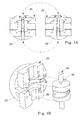
FIG. 1b is a perspective exploded view of the half of the vertical mold with a multi-piece plug.
FIG. 1c is another perspective exploded view of the half of the vertical mold with a multi-piece plug.
FIG. 2a is a perspective view of the multi-piece plug.
FIG. 2b is a perspective view of the multi-piece plug with a soluble insert and a ring replica.
FIG. 2c is another perspective view of the multi-piece plug with the soluble insert and the ring replica.
FIG. 3 is a perspective view of the insert mold.
FIG. 4 is a perspective view of the soluble insert.
FIG. 5 is a perspective view of the one half of the vertical mold, the multi-piece plug and the soluble insert as assembled.
FIG. 6 is a perspective view of a ring replica with the soluble insert.
FIG. 7 is a perspective view of the ring replica after removal of the soluble insert.
FIG. 8 is a plan view of the ring replica.
FIGS. 9A and 9B are perspective views of the facing mold half and backing old half used to form the setting.
FIG. 10 is a perspective view of the setting.
FIG. 11 is a perspective view of a metal ring with an attached metal setting.
FIG. 12 is a cross-sectional view of the ring shown in FIG. 11, taken along line 1212.
DETAILED DESCRIPTION OF THE PREFERRED EMBODIMENTS
While the inventive method described hereinafter pertains to the production of a metal jewelry ring, it will be apparent to those of ordinary skill in the art that the inventive method may be applied to produce a variety of articles and designs, using an array of manufacturing techniques and materials. The preferred method for achieving the inventive method is described as such for illustrative purposes only.
As defined and understood herein, a jewelry ring is capable of existing in a variety of forms and being used in numerous applications. A jewelry ring is generally circular and may be accompanied and attached with additional pieces, such as settings and/or precious stones. A jewelry ring is typically worn on a finger but given contemporary and evolving applications of jewelry rings, as defined herein, it can also be worn as a toe ring or used as an attachment to an ear or nose.
Contrary to the teachings of prior art, in the present invention a vertical mold is utilized to produce a jewelry ring 10 having a hollow portion and a beveled or rounded inner diameter on the shank 12 such as that shown in FIG. 11 and FIG. 12, wherein the inner diameter of the ring is of varying dimensions. Typically, as shown in FIG. 12, if observed from a cross-sectional view, the interior shape of a ring having such design is obtusely angled or generally parabolic.
To produce a ring replica having a beveled or rounded inner diameter on the shank, a vertically oriented mold configuration is utilized. As shown in FIGS. 1A-C, and 5 the ring mold 20 is oriented with the lower mold half 22, upper mold half 24, and a multi-piece plug 50 arranged to define a mold cavity 28 having the shape of the desired ring replica. Each mold half 22 and 24, in conjunction with the multi-piece plug 50, forms a mold cavity 28 defining substantially one-half the ring replica 40 in the radial direction, illustrated by a dashed line in FIG. 11.
As shown in FIGS. 2A-C, the plug 50 is a multi-piece plug consisting of at least two pieces 52, 54. Prior to being placed within the mold halves, 22, 24, or upon being placed within the mold halves 22, 24, the at least two pieces 52, 54 are connected together to form a substantially continuous plug 50, but the at least two pieces 52, 54 remain separable. A portion 56 of the multi-piece plug is inwardly angled or curved, i.e., it has a varying outer diameter or cross-sectional area so as to form the beveled or rounded inner diameter on the shank 12 of the ring. The multi-piece plug 50 preferably includes at least one locator pin 58 that locates the plug 50 in one of the mold halves 22, 24, of the vertical mold 20. Similarly, at least one piece 52 or 54 of the multi-piece plug 50 includes at least one locking means 60 that holds at least the first piece 52 and the second piece 54 of the multi-piece plug 50 together in the proper orientation. It is believed that this locking means 60 relieves stress on the soluble insert 30 preventing cracking of the soluble insert 30 during the introduction of the molten material into the mold cavity 28.
The mold halves 22, 24, and the multi-piece plug 50 may be produced by a variety of methods. For example, conventional tooling may be utilized to shape the mold halves 22, 24, and multi-piece plug 50 to form the desired mold cavity 28. Other methods include casting, hand machining, and the use of resins which can be molded to the desired shape. Each of the mold halves 22, 24, and the multi-piece plug 50 can be made by the same method or each part can be made by a different method. As will be appreciated by those of ordinary skill in the art, the desired shape and size of the mold halves 22, 24 and multi-piece plug 50 should allow for shrinkage of a molten material, such as wax or plastic, as it solidifies within the mold cavity 28. Furthermore, the mold halves 22, 24 and multi-piece plug 50 should be constructed of material capable of containing molten material such as wax or plastic without deformation, and of forming said molten material in sufficient detail to produce the desired ring design. The mold halves 22, 24 and multi-piece plug 50 may therefore be formed of brass, other metals, resins, or any materials capable of withstanding the temperature, thermal stresses, and pressure associated with the ring replica molding process. In addition, such material should have adequate heat transfer capabilities for proper and rapid cooling of the molten material. In one embodiment, the mold halves have sufficient strength that they require no additional support, such as a mold box, to withstand the molding pressures.
The ring mold 20 is used in conjunction with a soluble insert 30 to produce a ring replica 40 of a hollow or partially hollow construction.
A soluble insert 30 is an insert made of a material that is soluble in one or more solvents. For example, water soluble waxes are well known and used in the industry. Ceramics soluble in acidic solutions are well known and used in the jewelry industry. In making a ring replica 40 with a hollow or partially hollow construction, a soluble insert 30, such as that shown in FIG. 4, is positioned within mold half 22 or 24, prior to introduction of the molten material. See FIG. 5. The soluble insert 30 may be positioned anywhere within the mold cavity and may be secured by alignment means, such as alignment bars 64 which correspond with grooves 66 formed within the multi-piece plug 50. The soluble insert 30 may be positioned by other methods known in the art such as pegs or stops. Such alignment means serve to maintain the position and stability of the soluble insert 30 during injection of the molten material into the mold cavity 28. In addition, they provide for better airflow within the mold 20, reducing flashing problems that may occur during formation of the ring replica 40. Typically, such soluble insert 30 is positioned within the crown portion 68 of the mold cavity 28.
The soluble insert 30 may be produced by utilizing an insert mold 70, as shown in FIG. 3. Such an insert mold 70 comprises at least an upper and lower mold half formed with a cavity 76 in the shape of the desired soluble insert 30. The insert mold 70 can be formed so as to form alignment means, for example, at least one alignment bar 64. The alignment bar 64 may be configured so that the soluble insert 30 can be held in position by the multi-piece plug 50. The alignment bar 64 also provides a means to collect any gases trapped within the insert mold 70, thereby ensuring proper filling of the soluble insert 30 without air pockets.
Typically, the soluble insert 30 will be of a shape generally similar to that of the crown portion 68 of the ring, but slightly reduced in size so as to allow molten material to flow around the shape of the soluble insert 30 to form the outer wall of the ring 10. Preferably, there is an offset of approximately 0.021 to 0.030 inches between the soluble insert 30 and the inner wall of the mold cavity 28 to form jewelry rings of suitable wall-thickness and strength. Methods of producing soluble inserts 30 are known in the art. For example, see Japanese Laid Open Patent Application 2-232002, filed Mar. 7, 1989 which is incorporated herein by reference. It is conceivable that other processes, such as machining, may be used to produce the soluble insert 30.
In another embodiment, the soluble insert 30 can be formed so as to include a top cap 80. The top cap 80 allows the top of the crown portion 68 of the ring replica 40 to be formed within the vertical mold 20, without the use of an additional die insert. In this way, one vertical mold 20 can be used to form more than one ring replica design. The top cap 80 is shaped to include the features desired in the crown portion 68 of the ring replica 40. When the molten material is introduced into the mold cavity, it flows around the top cap 80, giving the desired shape to the ring replica 40.
Molten material is introduced into the mold cavity 28. Equipment suitable for adequately melting such molten material prior to introduction into the mold cavity 28 is well known and commercially available. Furthermore, introduction of said molten material into the mold cavity 28 should be conducted in a manner which facilitates the escape of all excess air or gases from within the mold cavity 28. Such methods are well known to those of ordinary skill in the art. For example, a “wax pot” subject to adequate pressure and heat may be used to melt and inject the molten material into the mold cavity 28.
Once the molten material has sufficiently cooled and/or hardened, the ring replica 40 is removed from the return mold 20. As shown in FIGS. 2A-C, to facilitate such removal, the multi-piece plug 50, can be equipped with handles 82. The handles 82 allow the ring replica 40 and the multi-piece plug 50 to be removed from the mold halves 22, 24 more easily and without damaging the ring replica 40.
Having a beveled or rounded inner diameter on the shank, it is not possible to “slidably” remove the ring replica 40 from the multi-piece plug 50 as it exists in its entirety. To remove the ring replica 40 from the multi-piece plug 50, the first piece of the plug 52 is separated from the second piece 54, releasing the ring replica 40 from the multi-piece plug 50 completely. In a separate embodiment, the multi-piece plug 50 may consist of more than two pieces. In such case, the plug would be similarly separated into its individual pieces to release the ring replica.
As shown in FIG. 6, the ring replica 40 after removal from the multi-piece plug 50 contains the soluble insert defining the desired hollow portion of the ring body. The soluble insert 30, being soluble, is then removed from the ring replica 40 by exposure of the ring replica 40 to the proper solution, in a manner well known in the art, resulting in a ring replica 40 of a hollow or partially hollow construction. See FIG. 7. The hollow portion 90 can have an arcuate length greater than 180°. The hollow portion 90 extends from one side of the alignment bar 64 to the other side. See FIG. 6.
The ring replica 40 made by the process of the present invention can be used to produce a metal ring by the lost wax casting method which is well known in the art. In such a method, ring replicas 40 are placed on a wax pole to form a “tree,” which is subsequently encased in a cylinder of investment material. Plaster-of-Paris, containing gypsum and silica, is typically used as the investment material. Investment materials are well-known in the art and any suitable investment material may be used with the ring replica of the present invention. During the investment process, the investment material may be placed under a vacuum to remove air from the material. The cylinder of investment material is subsequently dewaxed i.e., the ring replica is melted and/or baked out of the investment material. The baked investment material then defines an investment mold cavity in the shape of the original wax tree. By introducing molten metal, such as gold, platinum, or any desired metal into the investment mold cavity, a metal tree is formed. The investment material may be removed from the tree by various means, such as pressurized water removal. The cast metal rings or ring portions formed are removed from the tree, for example by clipping. The metal rings may then be polished and finished.
A metal setting 100 may be attached to the finished metal ring 10. Such a setting 100 is shown in FIG. 11 and is formed by utilizing backing and facing mold halves 120, 122 such as that shown in FIG. 9. In a manner similar to forming a ring replica 40, a setting replica 130 is formed within the backing and facing mold halves 120, 122. Such a setting replica 130 is generally formed of plastiwax, although any suitable wax or plastic known in art the can be used. Subsequently, metal settings are formed in a lost wax investment casting process similar to that described above for making metal rings or ring portions.
In a separate embodiment, the multi-piece plug 50 may consist of more than two pieces. In such case, the multi-piece plug 50 would be separated into its individual pieces to release the ring replica 40.
While the inventive method presented has been described with respect to specific embodiments, it should be well recognized that such method includes any and all changes and modifications thereto which would be apparent to those skilled in the art and which come within the spirit and scope of the appended claims.

Claims (12)

What is claimed is:
1. A method of producing a jewelry ring with a shank and a hollow portion comprising the steps of:
providing a vertical mold comprising an upper mold half and lower mold half;
providing a multi-piece plug comprising at least a first piece and a second piece to form a ring with a beveled or rounded interior design on the shank, wherein the multi-piece plug has at least two outer diameters;
providing a soluble insert;
positioning said soluble insert and said multi-piece plug within said vertical mold so as to form a mold cavity;
introducing molten material into said mold cavity;
cooling said molten material to form a ring replica;
separating the upper mold half and lower mold half;
removing the multi-piece plug with said ring replica formed around it from within the upper mold half or lower mold half;
separating said first piece of said multi-piece plug from said second piece, thereby releasing said ring replica from said multi-piece plug;
dissolving the insert from said ring replica; and
casting a jewelry ring using said ring replica in an investment casting process.
2. A method according to claim 1, wherein said multi-piece plug comprises at least three pieces.
3. A method according to claim 1, wherein said soluble insert is formed of water soluble wax.
4. A method according to claim 1, wherein said soluble insert is formed with alignment means.
5. A method according to claim 4, wherein the alignment means comprises at least one alignment bar.
6. A method according to claim 1, wherein said soluble insert is formed with a top cap.
7. A method of producing a ring replica comprising the steps of:
providing a vertical mold comprising an upper mold half and a lower mold half;
providing a multi-piece plug comprising at least a first piece and a second piece to form a ring with a shank and having a beveled or rounded interior design on the shank, wherein the multi-piece plug has at least two outer diameters;
providing a soluble insert;
positioning said soluble insert and said multi-piece plug within said vertical mold so as to form a mold cavity;
introducing molten material into said mold cavity;
cooling said molten material to form a ring replica;
separating the upper mold half from the lower mold half;
removing said multi-piece plug with said ring replica formed around it from the upper mold half or lower mold half; and
separating said first piece of said multi-piece plug from said second piece thereby releasing said ring replica from said multi-piece plug.
8. A method according to claims 7, wherein said multi-piece plug comprises at least three pieces.
9. A method according to claim 7, wherein said soluble insert is formed of water soluble wax.
10. A method according to claim 7, wherein said soluble insert is formed with alignment means.
11. A method according to claim 10, wherein the alignment means comprises at least one alignment bar.
12. A method according to claim 7, wherein said soluble insert is formed with a top cap.
US09/694,723 2000-10-23 2000-10-23 Method of making a jewelry ring in a vertical mold Expired - Lifetime US6467526B1 (en)

Priority Applications (1)

Application Number Priority Date Filing Date Title
US09/694,723 US6467526B1 (en) 2000-10-23 2000-10-23 Method of making a jewelry ring in a vertical mold

Applications Claiming Priority (1)

Application Number Priority Date Filing Date Title
US09/694,723 US6467526B1 (en) 2000-10-23 2000-10-23 Method of making a jewelry ring in a vertical mold

Publications (1)

Publication Number Publication Date
US6467526B1 true US6467526B1 (en) 2002-10-22

Family

ID=24790019

Family Applications (1)

Application Number Title Priority Date Filing Date
US09/694,723 Expired - Lifetime US6467526B1 (en) 2000-10-23 2000-10-23 Method of making a jewelry ring in a vertical mold

Country Status (1)

Country Link
US (1) US6467526B1 (en)

Cited By (5)

* Cited by examiner, † Cited by third party
Publication number Priority date Publication date Assignee Title
US20060090870A1 (en) * 2004-11-04 2006-05-04 Ervant Hashimian Hollow jewelry ring design
US20080229783A1 (en) * 2007-03-20 2008-09-25 Unimold Cast Limited Hollow metal jewelry ring
WO2010032255A1 (en) * 2008-09-22 2010-03-25 Jewelex India Pvt. Ltd. Hollow jewelry
CN101474661B (en) * 2008-01-04 2011-12-28 深圳市百泰珠宝首饰有限公司 Method for casting jewellery, method for producing gel mold thereof and gel mold thereof
CN114769510A (en) * 2022-03-30 2022-07-22 贺州市旭平首饰有限公司 Lost wax casting method for jewelry

Citations (31)

* Cited by examiner, † Cited by third party
Publication number Priority date Publication date Assignee Title
US404956A (en) 1889-06-11 Island
US703170A (en) 1901-08-01 1902-06-24 Frederick Baldt Sr Process of casting chains.
US840946A (en) 1906-08-07 1907-01-08 Charles M Levy Ring.
US1050370A (en) 1911-09-19 1913-01-14 George Cotton Mcglashan Manufacture of chains.
US1285882A (en) 1917-07-17 1918-11-26 Mieczyslaw Zielinski Finger-ring.
US1365702A (en) 1918-05-04 1921-01-18 Nat Malleable Castings Co Manufacture of cast-steel chain
US1365672A (en) 1918-05-04 1921-01-18 Nat Malleable Castings Co Manufacture of cast-steel chain
US1398706A (en) 1918-02-18 1921-11-29 Robert R Rust Method of making cast chains
US2078562A (en) 1936-12-15 1937-04-27 Cohen Abraham Casting
US2103413A (en) 1936-10-01 1937-12-28 Frederick J Gaertner Method of making finger rings
US3302257A (en) * 1964-08-04 1967-02-07 Morton S Kaplan Method for casting rings by the lost wax process
US3401738A (en) 1966-02-10 1968-09-17 United Aircraft Corp Core location in precision casting
US3511466A (en) 1967-03-28 1970-05-12 Microthermal Applic Inc Mold for wax patterns for casting finger rings
US3554875A (en) 1968-08-01 1971-01-12 Budd Co Method of fabricating a mandrel for electroforming
US3561521A (en) 1969-02-27 1971-02-09 Micro Thermal Applic Inc Method for changing the size of wax ring patterns
US3562900A (en) 1966-10-19 1971-02-16 Buehler Corp Method of making a jewelry mold
US3838728A (en) 1973-06-01 1974-10-01 Jostens Inc Method for molding finger rings
US3991809A (en) 1975-03-10 1976-11-16 Josten's, Inc. Method of molding finger rings
US4392289A (en) 1981-06-01 1983-07-12 Charles Hoffert Of America, Inc. Manufacture of jewelry by casting with preset gems
US4530740A (en) 1983-04-28 1985-07-23 Messerschmitt-Bolkow-Blohm Gmbh Method of producing closed canals in components such as heat exchangers and rocket combustion chamber walls
US4630346A (en) 1985-03-20 1986-12-23 Singer Steven M Article forming method
US4681664A (en) 1985-03-19 1987-07-21 Juwedor Gmbh Process for producing pieces of jewelry from precious metals and pieces of jewelry produced by it
US4710276A (en) 1985-12-16 1987-12-01 Juwedor Gmbh Process for the galvanoplastic production of jewelry
US4722770A (en) 1985-07-25 1988-02-02 Universite Paul Sabatier Method for making continuous and closed hollow bodies, hollow bodies so obtained and apparatus for making the hollow spheres
US4761206A (en) 1987-02-17 1988-08-02 Norman Forrest Method for producing large reinforced seamless casings and the product obtained therefrom
US4811778A (en) 1987-06-03 1989-03-14 Rolls-Royce Plc Method of manufacturing a metal article by the lost wax casting process
JPH0232002A (en) 1988-07-22 1990-02-01 Norin Suisansyo Nogyo Kankyo Gijutsu Kenkyusho Insect attractant containing (e)-7,9-deadienyl acetate as additional component
US5172568A (en) 1988-09-09 1992-12-22 Senanayake Daya R Hollow jewelry objects and method
US5393405A (en) 1993-12-01 1995-02-28 Ultralite Technology Incorporated Method of electroforming a gold jewelry article
US5606873A (en) 1995-06-07 1997-03-04 Astoria Jewelry Mfg. Co., Inc. Finger ring
US5718278A (en) * 1995-12-13 1998-02-17 Baum; Robert Method for producing hollow ring having inner round radius design

Patent Citations (34)

* Cited by examiner, † Cited by third party
Publication number Priority date Publication date Assignee Title
US404956A (en) 1889-06-11 Island
US703170A (en) 1901-08-01 1902-06-24 Frederick Baldt Sr Process of casting chains.
US840946A (en) 1906-08-07 1907-01-08 Charles M Levy Ring.
US1050370A (en) 1911-09-19 1913-01-14 George Cotton Mcglashan Manufacture of chains.
US1285882A (en) 1917-07-17 1918-11-26 Mieczyslaw Zielinski Finger-ring.
US1398706A (en) 1918-02-18 1921-11-29 Robert R Rust Method of making cast chains
US1365702A (en) 1918-05-04 1921-01-18 Nat Malleable Castings Co Manufacture of cast-steel chain
US1365672A (en) 1918-05-04 1921-01-18 Nat Malleable Castings Co Manufacture of cast-steel chain
US2103413A (en) 1936-10-01 1937-12-28 Frederick J Gaertner Method of making finger rings
US2078562A (en) 1936-12-15 1937-04-27 Cohen Abraham Casting
US3302257A (en) * 1964-08-04 1967-02-07 Morton S Kaplan Method for casting rings by the lost wax process
US3401738A (en) 1966-02-10 1968-09-17 United Aircraft Corp Core location in precision casting
US3562900A (en) 1966-10-19 1971-02-16 Buehler Corp Method of making a jewelry mold
US3511466A (en) 1967-03-28 1970-05-12 Microthermal Applic Inc Mold for wax patterns for casting finger rings
US3554875A (en) 1968-08-01 1971-01-12 Budd Co Method of fabricating a mandrel for electroforming
US3561521A (en) 1969-02-27 1971-02-09 Micro Thermal Applic Inc Method for changing the size of wax ring patterns
US3838728A (en) 1973-06-01 1974-10-01 Jostens Inc Method for molding finger rings
US3991809A (en) 1975-03-10 1976-11-16 Josten's, Inc. Method of molding finger rings
US4392289A (en) 1981-06-01 1983-07-12 Charles Hoffert Of America, Inc. Manufacture of jewelry by casting with preset gems
US4530740A (en) 1983-04-28 1985-07-23 Messerschmitt-Bolkow-Blohm Gmbh Method of producing closed canals in components such as heat exchangers and rocket combustion chamber walls
US4681664A (en) 1985-03-19 1987-07-21 Juwedor Gmbh Process for producing pieces of jewelry from precious metals and pieces of jewelry produced by it
US4630346A (en) 1985-03-20 1986-12-23 Singer Steven M Article forming method
US4722770A (en) 1985-07-25 1988-02-02 Universite Paul Sabatier Method for making continuous and closed hollow bodies, hollow bodies so obtained and apparatus for making the hollow spheres
US4710276A (en) 1985-12-16 1987-12-01 Juwedor Gmbh Process for the galvanoplastic production of jewelry
US4761206A (en) 1987-02-17 1988-08-02 Norman Forrest Method for producing large reinforced seamless casings and the product obtained therefrom
US4811778A (en) 1987-06-03 1989-03-14 Rolls-Royce Plc Method of manufacturing a metal article by the lost wax casting process
JPH0232002A (en) 1988-07-22 1990-02-01 Norin Suisansyo Nogyo Kankyo Gijutsu Kenkyusho Insect attractant containing (e)-7,9-deadienyl acetate as additional component
US5172568A (en) 1988-09-09 1992-12-22 Senanayake Daya R Hollow jewelry objects and method
US5393405A (en) 1993-12-01 1995-02-28 Ultralite Technology Incorporated Method of electroforming a gold jewelry article
US5606873A (en) 1995-06-07 1997-03-04 Astoria Jewelry Mfg. Co., Inc. Finger ring
US5718278A (en) * 1995-12-13 1998-02-17 Baum; Robert Method for producing hollow ring having inner round radius design
US5916271A (en) 1995-12-13 1999-06-29 Baum; Robert Hollow jewelry ring having inner round design
US5979537A (en) 1995-12-13 1999-11-09 Baum; Robert Wax replica and soluble core insert used for producing hollow jewelry ring
US6032719A (en) 1995-12-13 2000-03-07 Baum; Robert Method for producing hollow jewelry ring

Non-Patent Citations (4)

* Cited by examiner, † Cited by third party
Title
More than a year before the filing of the present invention, it has also known in the art to manufacture a hollow jewelry ring using a lost-wax casting process. The hollow wax replica ring used for the lost-wax casting is formed by molding plastiwax around a water soluble wax core insert in a vertical metal mold. The vertical mold is closed around a cylindrical core or mandrel. The wax core insert is generally arcuate in shape and has a respective spacer pin extending radially inwardly from each end of the arcuate core insert. The arcuate extent of the arcuate core insert is substantially 130°. A sprue terminating with an alignment peg extended radially inwardly from a central part of the arcuate core insert. The cylindrical mandrel is formed of two pieces which are locked together t form the mandrel while defining a receptacle to accommodate the alignment peg of the wax core. After the wax replica is formed around the core insert, the core insert is dissolved to yield a hollow
More than a year before the filing of the present invention, it was known in the art to use a vertical mold with a multi-piece plug to form a ring of solid construction, i.e, no hollow portion, with a rounded or beveled inside diameter.
More than one year before the patent application was filed, it was known to use a horizontal mold with a multi-piece plug to manufacture an open back ring with a straight inner radius on the ring shank.
space within the replica. The hollow wax replica is then used for a conventional lost-wax (investment) casting step. The prior art ring has an inner (finger-facing) surface that was cylindrical. That is, the prior art ring has a "flat' inner radius design.

Cited By (9)

* Cited by examiner, † Cited by third party
Publication number Priority date Publication date Assignee Title
US20060090870A1 (en) * 2004-11-04 2006-05-04 Ervant Hashimian Hollow jewelry ring design
US7080678B2 (en) 2004-11-04 2006-07-25 Unimold Cast Ltd. Hollow jewelry ring design
US20080229783A1 (en) * 2007-03-20 2008-09-25 Unimold Cast Limited Hollow metal jewelry ring
US7637123B2 (en) 2007-03-20 2009-12-29 Unimold Cast Ltd. Hollow metal jewelry ring
CN101474661B (en) * 2008-01-04 2011-12-28 深圳市百泰珠宝首饰有限公司 Method for casting jewellery, method for producing gel mold thereof and gel mold thereof
WO2010032255A1 (en) * 2008-09-22 2010-03-25 Jewelex India Pvt. Ltd. Hollow jewelry
US8966762B2 (en) 2008-09-22 2015-03-03 Jewelex India Pvt. Ltd. Hollow jewelry
CN114769510A (en) * 2022-03-30 2022-07-22 贺州市旭平首饰有限公司 Lost wax casting method for jewelry
CN114769510B (en) * 2022-03-30 2024-01-09 贺州市旭平首饰有限公司 Method for lost wax casting of jewelry

Similar Documents

Publication Publication Date Title
US5916271A (en) Hollow jewelry ring having inner round design
US2420851A (en) Method of making patterns and use thereof
ES2622069T3 (en) Neck ring and manufacturing method for a glass container forming machine
US4283831A (en) Method of manufacturing and interlocking jewelry with precise preforms
US6467526B1 (en) Method of making a jewelry ring in a vertical mold
CA2125152A1 (en) Process for producing cast and set pieces of jewellery
EP0873803B1 (en) Production process of wax pattern
DE60306798D1 (en) TIREFORMING TOOL AND METHOD FOR THE PRODUCTION THEREOF
US8966762B2 (en) Hollow jewelry
US20090308559A1 (en) Hollow articles and method of manufacture
US6554052B2 (en) Method for producing hollow jewelry ring design
KR100675526B1 (en) Precious Metal Ornament Casting Method
JPH05185179A (en) Mold with built-in feeder unit divided vertically
US20060096731A1 (en) Ball-shaped jewelry and method of making same
US20030047299A1 (en) Investment molding flask assembly
CN107334232A (en) A kind of manufacture method of hollow diamond ring and hollow diamond ring structure
US6619378B1 (en) Lost core method of molding gemstone seats
US7080678B2 (en) Hollow jewelry ring design
US12220846B2 (en) Molding assembly
JPH07112617B2 (en) Casting method for double layer casting
JP4084589B2 (en) Manufacturing method of golf club head
KR100891196B1 (en) Casting method using fresh flowers
RU2151023C1 (en) Method of manufacturing hollow jewelry
CN117731095A (en) Chain jewelry integrated forming process and chain jewelry
US747058A (en) Finger-ring mold.

Legal Events

Date Code Title Description
AS Assignment

Owner name: I.B. GOODMAN MANUFACTURING CO., INC., OHIO

Free format text: ASSIGNMENT OF ASSIGNORS INTEREST;ASSIGNOR:COPE, STEVEN;REEL/FRAME:011268/0751

Effective date: 20001023

STCF Information on status: patent grant

Free format text: PATENTED CASE

FPAY Fee payment

Year of fee payment: 4

FPAY Fee payment

Year of fee payment: 8

FPAY Fee payment

Year of fee payment: 12

AS Assignment

Owner name: QUALITY GOLD, INC., OHIO

Free format text: ASSIGNMENT OF ASSIGNORS INTEREST;ASSIGNOR:I.B. GOODMAN MANUFACTURING CO., INC.;REEL/FRAME:062684/0236

Effective date: 20220701