US6463388B1 - Method and system for attenuation of acquisition geometry imprint in seismic data - Google Patents
Method and system for attenuation of acquisition geometry imprint in seismic data Download PDFInfo
- Publication number
- US6463388B1 US6463388B1 US09/658,057 US65805700A US6463388B1 US 6463388 B1 US6463388 B1 US 6463388B1 US 65805700 A US65805700 A US 65805700A US 6463388 B1 US6463388 B1 US 6463388B1
- Authority
- US
- United States
- Prior art keywords
- amplitudes
- seismic data
- weights
- data
- time slice
- Prior art date
- Legal status (The legal status is an assumption and is not a legal conclusion. Google has not performed a legal analysis and makes no representation as to the accuracy of the status listed.)
- Expired - Fee Related, expires
Links
- 238000000034 method Methods 0.000 title claims abstract description 67
- 238000009499 grossing Methods 0.000 claims description 21
- 230000001131 transforming effect Effects 0.000 claims description 18
- 238000001914 filtration Methods 0.000 claims 16
- 230000000694 effects Effects 0.000 description 5
- 238000010586 diagram Methods 0.000 description 4
- 239000004215 Carbon black (E152) Substances 0.000 description 3
- 238000012937 correction Methods 0.000 description 3
- 229930195733 hydrocarbon Natural products 0.000 description 3
- 150000002430 hydrocarbons Chemical class 0.000 description 3
- 238000012512 characterization method Methods 0.000 description 2
- 238000009826 distribution Methods 0.000 description 2
- 238000012986 modification Methods 0.000 description 2
- 230000004048 modification Effects 0.000 description 2
- 238000012544 monitoring process Methods 0.000 description 2
- 238000012545 processing Methods 0.000 description 2
- 238000012552 review Methods 0.000 description 2
- 230000002238 attenuated effect Effects 0.000 description 1
- 230000001427 coherent effect Effects 0.000 description 1
- 238000007598 dipping method Methods 0.000 description 1
- 239000012530 fluid Substances 0.000 description 1
- 230000003278 mimic effect Effects 0.000 description 1
- 230000000737 periodic effect Effects 0.000 description 1
- 230000004044 response Effects 0.000 description 1
- 230000009897 systematic effect Effects 0.000 description 1
Images


Classifications
-
- G—PHYSICS
- G01—MEASURING; TESTING
- G01V—GEOPHYSICS; GRAVITATIONAL MEASUREMENTS; DETECTING MASSES OR OBJECTS; TAGS
- G01V1/00—Seismology; Seismic or acoustic prospecting or detecting
- G01V1/28—Processing seismic data, e.g. for interpretation or for event detection
- G01V1/36—Effecting static or dynamic corrections on records, e.g. correcting spread; Correlating seismic signals; Eliminating effects of unwanted energy
- G01V1/362—Effecting static or dynamic corrections; Stacking
-
- G—PHYSICS
- G01—MEASURING; TESTING
- G01V—GEOPHYSICS; GRAVITATIONAL MEASUREMENTS; DETECTING MASSES OR OBJECTS; TAGS
- G01V2210/00—Details of seismic processing or analysis
- G01V2210/50—Corrections or adjustments related to wave propagation
- G01V2210/52—Move-out correction
Definitions
- the AGI distortion originates when seismic data is acquired with variable offsets, fold, and/or azimuth distributions.
- the offset, fold, and/or azimuth distribution is not uniform, steeply dipping residual coherent noise or residual multiple reflections, or any other seismic interference, will intercept the primary reflections at different offsets and/or azimuths having an effect in the stack response.
- This effect causes the stack to produce spatial periodic variations in the stacked amplitude, thus resulting in organized spatial amplitude distortions that can mimic the field geometry (Gulunay et al. 1994), incorporated herein by reference.
- this acquisition geometry imprint creates a systematic distortion in the seismic data. This phenomenon is observed more clearly as high or low amplitude bands or strips in time slices taken from three dimensional stacked seismic data volumes. As mentioned earlier, this spurious energy masks the true relative amplitudes that are useful for interpretation purposes.
- the present invention provides a method and system for attenuation of acquisition geometry imprint in seismic data.
- the method of one embodiment of the present invention includes receiving seismic data.
- this data is in the form of common midpoint (CMP) gathers with normal moveout correction (NMO) applied.
- CMP gathers contain the data in the time-offset-azimuth domain.
- the amplitudes of the seismic data are raised to a predetermined power.
- the reciprocal of the raised amplitude data is computed to produce weights.
- a time slice across a CMP gather of the weights is selected, and the weights of the time slice are stacked.
- the original input amplitudes are scaled using the weights and stacked.
- the stacked scaled weighted amplitudes are divided by the stacked weights to produce the output amplitudes.
- the amplitudes of seismic data with the normal moveout correction (NMO) applied are squared.
- the squared amplitude data is then inverted to produce weights.
- a time slice of the weights and seismic data is selected, and the amplitudes of the time slice of the inverted data are divided into sets.
- the inverted data is multiplied by the raw amplitudes to obtain the scaled data.
- the scaled data is stacked, and the weights are also stacked.
- a model amplitude corresponding to each set is developed and centered at the middle of the minimum and maximum offset in each set of amplitudes.
- the representative offset values for each set are transformed, and a parabola is fitted to the transformed representative offset values for each set.
- the originally received offsets of the received seismic data are then transformed.
- Model amplitudes are computed at all the originally received transformed offsets, and the model amplitudes are compared to the real amplitudes and a difference value is calculated. If the difference value exceeds a predetermined threshold, the real amplitudes are scaled to match the model amplitudes, and the scaled amplitudes are used to produce a new parabolic model of scaled amplitudes across the time slice for the second time.
- the parabolic model of the amplitudes is used to predict the output amplitude at zero offset for the current time slice. Then, the process continues to the next time slice until the maximum recorded time is reached.
- FIG. 1 is a block diagram of one embodiment of a method of the present invention.
- FIGS. 2A, 2 B, and 2 C are a block diagram of another embodiment of a method of the present invention.
- FIG. 3 is a block diagram of one embodiment of a system of the present invention.
- FIGS. 4A, 4 B, and 4 C are a block diagram of another embodiment of a system of the present invention.
- a method and system for attenuating the acquisition geometry imprint is provided.
- Example embodiments of the present invention is compared with FIG. 1 for a more complete understanding of the present invention.
- seismic data is received.
- CMP common midpoint
- NMO normal moveout
- other types of gathers will be used. Such alternate gathers are shot gathers, receiver gathers, and any other gather as will occur to one of ordinary skill in the art.
- the input real amplitude traces are converted to the n th power values by raising the real amplitudes to the n th power.
- the n th power is any power that produces workable data.
- the n th power is either the first or the second power.
- the amplitudes are either kept the same or squared.
- the amplitudes are raised 14 to any other power which will occur to one of ordinary skill in the art.
- n th power traces are then inverted 15 to obtain the weights w.
- weights w are provided manually.
- the inverted n th power values or the weights, or both are then smoothed in time.
- the weights data are smoothed with a filter.
- this filter is a Boxcar, Bartlett, Gaussian, or other type of filter that will occur to those of skill in the art.
- this filter will have a predefined length.
- other methods of smoothing the data such as polynomial fitting, splines, digital bandpass filters, or any other method that will occur to those of ordinary skill in the art used.
- a time slice of the seismic data (real amplitudes) and the inverted data (weights) is selected.
- the selected amplitudes are scaled 20 with the inverted data.
- the scaled data is stacked 23 .
- the weights are stacked 25 .
- n n th power.
- the resulting amplitude S w is the estimated amplitude at zero offset with the AGI distortion attenuated.
- various methods of stacking are used. Examples of such alternate methods are median stack, trimmed stack, or any other method of stacking that will occur to one of ordinary skill in the art.
- the data is reviewed to determine if the time slice being considered is the i th time slice or the last time slice. If it is the last time slice, in an even further embodiment, the data may be displayed at block 60 . To determine if this is the last time slice, the time of the time slice is compared with the maximum recording time. If the time of the time slice is not the last time slice, the process returns to block 19 , a new time slice is selected, and real amplitudes are scaled with inverted data at block 20 . The process is repeated for the next time slice in the gather. In an even further embodiment, once it is determined that the time slice is acceptable, it is displayed 60 . Various methods of displaying data are on paper, on the screen or a monitor, or any other method that will occur to one of ordinary skill in the art.
- seismic data is received.
- This seismic data maybe in various forms, for example, in common midpoint gathers or in any other form that would occur to one of ordinary skill in the art.
- the amplitudes of the data are raised to a predetermined power (n th power), where n is any number. Typically, in alternate embodiments, n is 1 or 2.
- the n th power values are then smoothed when needed.
- the smoothing is accomplished with a filter such as a Boxcar, Bartlett, Gaussian, or other filter that will occur to those of skill in the art.
- this filter has a predefined length.
- smoothing is not needed.
- smoothing is accomplished by polynomial fitting, spline fitting, bandpass filters, or any other method that will occur to those skilled in the art.
- the n th power values are inverted at block 15 to obtain weights w.
- a time slice of the inverted data (weights) and real amplitudes is selected.
- the seismic data (real amplitudes) are scaled with the weights.
- the scaled data and the inverted data (weights) of the time slice are divided into sets. The number of sets may be any number that produces workable numbers.
- the amplitudes are divided into three equal sets. Since the number of amplitudes are not always a multiple of three, for example, the three sets may not always contain exactly the same number of amplitudes. In other embodiments, a different number of sets will be used as will occur to those of ordinary skill in the art.
- the amplitudes of each set of the inverted data (weights) and scaled data are stacked for a given set and time slice.
- n n th power.
- each of the three stacks is centered at the middle of the minimum and maximum offset in each set of amplitudes.
- the results are three model amplitudes for each time slice.
- representative offset values are determined for each set.
- the three model amplitudes for example, S 1 , S 2 , and S 3 , have three corresponding representative offsets, x 1 , x 2 , and x 3 , respectively. These offsets are centered at each selected amplitude set.
- each representative offset value is the average of the minimum and maximum offsets in the selected set.
- a parabola is fitted to the model amplitudes. Using the three model amplitudes a parabola is fitted 32 versus the sin 2 ( ⁇ ).
- the parabolic model is characterized by the following equation:
- the parabolic fitting produces three coefficients: b 0 , b 1 , and b 2 .
- any other coefficients produced from a different shaped fitting are used.
- originally received offsets are transformed to the square offsets, square tangents of the angle of incidence, or any other domain which will occur to those of ordinary skill in the art.
- model amplitudes are now computed at all the transformed originally received offsets for the time slice. Using the coefficients previously computed, model amplitudes at every offset transformed to sin 2 ⁇ along the time slice are computed and compared to the real amplitudes at the same offsets transformed to sin 2 ⁇ . In an even further embodiment, any other amplitude may be computed and compared as will occur to those of ordinary skill in the art.
- the difference between the model amplitudes at the transformed originally received offsets and the real amplitudes at the same offset are checked against a predetermined threshold value. If the difference exceeds such threshold value, then the current real amplitude is scaled to match that of the modeled amplitude at block 38 creating edited real amplitudes. The real amplitudes exceeding the threshold value at this point could have been the cause of AGI distortion.
- the predetermined threshold is chosen a priori, as a percent of total amplitude, a measure in decibels, or any other predetermined threshold that will occur to those of ordinary skill in the art. The amplitudes are then saved.
- the edited real amplitudes at all offsets are used to perform another parabolic model corresponding to the following equation:
- the result will be a new set of coefficients which are denominated b′ 0 , b′ 1 , and b′ 2 .
- the amplitude corresponding to the coefficient value b′ 0 is the zero offset or predicted amplitude at zero offset without the AGI effect.
- the predicted amplitude at zero offset (b′ 0 ) is saved for the time slice.
- the processed data is reviewed to determine 29 if the time slice being considered is the i th time slice or the last time slice. If the time slice is not the last time slice, the process returns to block 19 and a new time slice is selected. If it is the last time slice, the data may be displayed 60 .
- Block 112 represents means for receiving.
- the means for receiving 112 obtains seismic data.
- means for receiving 112 is a digital computer capable of reading seismic traces from magnetic tape, a computer capable of storing seismic data, or any other means for receiving data that would occur to one of ordinary skill in the art.
- block 114 represents a means for raising amplitudes.
- This means for raising the real amplitude traces 114 converts the data to the n th power by raising the amplitudes of the real traces to the n th power.
- means for raising amplitudes 114 is a digital computer, software running on a digital computer, calculator, analog machine, or any other means capable of raising an amplitude to a power that will occur to one of ordinary skill in the art.
- means for computing weights 115 is provided.
- the means for computing weights 115 further comprises a means for inverting the n th power trace values to obtain weights w.
- the means for computing weights 115 is a digital computer, software running on a computer, an analog machine, or any other means that will occur to one of ordinary skill in the art. In alternate embodiments, weights are supplied manually.
- a means for smoothing smoothes the weights.
- the means for smoothing smoothes the weights with a Boxcar, Bartlett, Gaussian, or other filter that will occur to those of skill in the art.
- this filter has a predefined length.
- means for smoothing is a digital computer, software running on a computer, an analog machine, or any other means for smoothing data which will occur to one of ordinary skill in the art.
- block 119 represents a means for selecting.
- a means for selecting 119 selects a time slice and determines the amplitudes of the traces.
- means for selecting 119 is a digital computer, software running on a computer, an analog machine, and any other means for selecting 119 which will occur to one of ordinary skill in the art.
- block 120 represents a means for scaling.
- means for scaling 120 is a digital computer, software running on a computer, an analog machine, and any other means for scaling the amplitudes of seismic data.
- block 123 , 125 represents a means for stacking.
- a means for stacking 123 , 125 is provided which stacks the real amplitudes and stacks the weights.
- the means for stacking 123 , 125 is a digital computer, software running on a computer, an analog machine, or any other means for stacking that will occur to one of ordinary skill in the art.
- block 127 represents a means for dividing.
- means for dividing 127 is a digital computer, software running on a computer, an analog machine, or any other means that will occur to one of ordinary skill in the art.
- a means for determining 129 reviews the processed data to determine if the time slice being considered is the i th time slice or the last time slice. If it is the last time slice, the data may be transferred to a display means 160 for displaying the processed data.
- means for determining 129 is a digital computer, software running on a computer, an analog machine, or any other means that would occur to one of ordinary skill in the art. In alternate embodiments, means for determining 129 manually compares the time of the time slice to the maximum recording time.
- Means for displaying 160 comprises a device such as a monitor or a printout or any other means for displaying 160 that will occur to those of ordinary skill in the art.
- the data may be transferred to other methods for further processing as will occur to those of ordinary skill in the art.
- means for displaying is a printed seismograph, or any other means for displaying that will occur to those of ordinary skill in the art. If the time slice is not the last time slice, the means for comparing returns the data to means for selecting 119 . Means for selecting 119 selects a new time slice, and amplitudes of scaled and weight data are stacked and saved.
- means for receiving 112 receives seismic data.
- means for receiving 112 may be a part of a digital computer, such as a tape reader, or the like which can read data in electronic form and establish values to this data.
- means for receiving 112 is a digital computer, software running on a computer, an analog machine, or any other means for receiving seismic data that will occur to one of ordinary skill in the art.
- means for raising amplitudes 114 provides a means for raising the amplitudes to a predetermined n th power.
- means for raising amplitudes 114 is a digital computer, software running on a computer, an analog machine, or any other means for raising an amplitude to a n th power that will occur to those of ordinary skill in the art.
- the means for raising 114 converts the input real amplitude traces to n th power values.
- the means for creating weights 115 is provided.
- means for computing weights inverts the n th power traces to obtain the weights w.
- means for computing weights 115 is a digital computer, software running on a computer, an analog machine, or any other means for computing weights or inverting seismic data that will occur to one of ordinary skill in the art.
- a means for smoothing is provided.
- Means for smoothing smoothes the n th power values or weights.
- means for smoothing is a Boxcar, Bartlett, or Gaussian filter. This filter will have a predefined length in some embodiments.
- Other means for smoothing such as a digital computer, software running on a computer, an analog machine, will also occur to one of ordinary skill in the art as well as many others.
- means for selecting 119 selects a time slice and determines the amplitudes.
- means for selecting 119 is a digital computer, software running on a computer, an analog machine, or any other means for selecting that will occur to one of ordinary skill in the art.
- means for scaling 120 scales amplitudes. In various embodiments, means for scaling 120 scales real amplitudes, or any other data that will occur to those of ordinary skill in the art. In various embodiments, means for scaling 120 is a digital computer, software running on a computer, an analog machine, or any other means for selecting that will occur to one of ordinary skill in the art.
- a means for dividing amplitudes into sets 121 divides the amplitudes of the time slice into sets. Means 121 divides both the weights and the scaled data into sets.
- the means for dividing into sets 121 is a digital computer, software running on a computer, an analog machine, or any other means that will occur to those of ordinary skill in the art.
- the sets are divided manually.
- a means for stacking 122 stacks the amplitudes of each set of the time slice of the weights and scaled data.
- means for stacking 122 will stack the data in a digital computer, software running on a computer, an analog machine, or any other method that will occur to those of ordinary skill in the art.
- a means for developing a model amplitude 126 develops model amplitudes corresponding to each set.
- the means for developing 126 centers each of the three weighted stacks at the middle of the minimum and maximum offset included in each set of amplitudes.
- the results of the means for developing 126 are three model amplitudes for each time slice.
- the means for developing 126 is a digital computer, software running on a computer, an analog machine, or any other means 126 of developing model amplitudes that will occur to one of ordinary skill in the art.
- a means for determining the center of offset values 128 determines representative offset values.
- the three model amplitudes for example, s 1 , s 2 and s 3 , will have three corresponding representative offsets, x 1 , x 2 and x 3 , respectively.
- each offset value is the average of the minimum and maximum offsets in the selected set.
- a means for transforming the representative offset values 130 transforms the representative offsets to the sine square of the angle of incidence domain.
- means for transforming 130 is a digital computer, software running on a computer, an analog machine, or any other means that will occur to those of ordinary skill in the art.
- a means for fitting a parabola 132 fits a parabola to the transformed representative offset values for the selected data sets.
- means for fitting a parabola 132 is a digital computer, software running on a computer, an analog machine, or any other means that will occur to those of ordinary skill in the art.
- a means for transforming 133 the originally received offset values of the received seismic data transforms the originally received offsets to the sine square of the angle of incidence domain.
- means for transforming 133 is a digital computer, software running on a computer, an analog machine, or any other means that will occur to those of ordinary skill in the art.
- a means for computing model amplitudes 134 is provided. Model amplitudes are computed at all the transformed originally received offsets for the time slice.
- the means for computing 134 is a digital computer, software running on a computer, an analog machine, or any other means for computing an amplitude that will occur to one of ordinary skill in the art.
- means for comparing 136 the difference between the model amplitudes and the real or raw amplitudes is provided. Means 136 compares this difference with a a predetermined threshold value.
- the means for comparing 136 is a digital computer, software running on a computer, an analog machine, or any other means for comparing that will occur to one of ordinary skill in the art.
- means for scaling 138 is provided. If the difference exceeds such threshold value, then the current real amplitude is scaled to match that of the modeled amplitude. This creates edited amplitudes.
- means for scaling 138 is a digital computer, software running on a computer, an analog machine, or any other means that will occur to one of ordinary skill in the art.
- means for fitting a parabola to all the transformed originally received offsets 142 performs another parabolic fitting to the scaled amplitudes.
- the result will be a new set of coefficients which are denominated b′ 0 , b′ 1 , and b′ 2 .
- b′ 0 is then the current predicted amplitude at zero offset with no AGI effect. It is saved by a memory saving means 143 .
- means for saving 143 is a digital computer, software running on a computer, an analog machine, or any other means that will occur to one of ordinary skill in the art.
- means for determining 129 reviews the processed data to determine if the time slice being considered is the i th time slice or the last time slice. If the time slice is not the last time slice, the system returns to means for selecting 119 and a new time slice is selected. If it is the last time slice, the data is displayed by display means 160 .
- means for displaying 160 is a digital computer, software running on a computer, an analog machine, or any other means that will occur to those of ordinary skill in the art.
Landscapes
- Engineering & Computer Science (AREA)
- Remote Sensing (AREA)
- Physics & Mathematics (AREA)
- Life Sciences & Earth Sciences (AREA)
- Acoustics & Sound (AREA)
- Environmental & Geological Engineering (AREA)
- Geology (AREA)
- General Life Sciences & Earth Sciences (AREA)
- General Physics & Mathematics (AREA)
- Geophysics (AREA)
- Geophysics And Detection Of Objects (AREA)
Abstract
A method is disclosed for attenuating acquisition geometry imprint in seismic data. The method includes raising amplitudes of the data to a predetermined power, calculating weights, selecting a time slice of the seismic data and the weights, scaling the data with the weights, stacking the scaled data, stacking the weights, and dividing the stacked scaled data by the stacked weights.
Description
As it is well known, seismic amplitudes have been traditionally used to identify and quantify lithology and fluid types present in the subsurface. This reduces the overall risk in the hydrocarbon exploration and exploitation stages. Post stacked seismic data often show amplitude patterns that resemble the acquisition geometry. This is commonly referred to as “Acquisition Geometry Imprint (AGI).” One example where such patterns are often very noticeable is in time sliced data. These amplitude distortions can limit the value of the seismic amplitudes in applications such as hydrocarbon reservoir characterization and monitoring.
More specifically, the AGI distortion originates when seismic data is acquired with variable offsets, fold, and/or azimuth distributions. When the offset, fold, and/or azimuth distribution is not uniform, steeply dipping residual coherent noise or residual multiple reflections, or any other seismic interference, will intercept the primary reflections at different offsets and/or azimuths having an effect in the stack response. This effect causes the stack to produce spatial periodic variations in the stacked amplitude, thus resulting in organized spatial amplitude distortions that can mimic the field geometry (Gulunay et al. 1994), incorporated herein by reference. Thus, this acquisition geometry imprint creates a systematic distortion in the seismic data. This phenomenon is observed more clearly as high or low amplitude bands or strips in time slices taken from three dimensional stacked seismic data volumes. As mentioned earlier, this spurious energy masks the true relative amplitudes that are useful for interpretation purposes.
For all these reasons, the attenuation of the AGI effect is vital to provide high fidelity amplitudes after data processing. The impact of this correction is important because it affects the accuracy of the characterization and monitoring of hydrocarbon reservoirs. There is a long felt need for a method of attenuating the acquisition geometry imprint.
The present invention provides a method and system for attenuation of acquisition geometry imprint in seismic data. The method of one embodiment of the present invention includes receiving seismic data. In one example embodiment, this data is in the form of common midpoint (CMP) gathers with normal moveout correction (NMO) applied. In this example, the CMP gathers contain the data in the time-offset-azimuth domain. The amplitudes of the seismic data are raised to a predetermined power. The reciprocal of the raised amplitude data is computed to produce weights. A time slice across a CMP gather of the weights is selected, and the weights of the time slice are stacked. The original input amplitudes are scaled using the weights and stacked. The stacked scaled weighted amplitudes are divided by the stacked weights to produce the output amplitudes.
In another embodiment of the present invention, the amplitudes of seismic data with the normal moveout correction (NMO) applied are squared. The squared amplitude data is then inverted to produce weights. A time slice of the weights and seismic data is selected, and the amplitudes of the time slice of the inverted data are divided into sets. In each of the sets, the inverted data is multiplied by the raw amplitudes to obtain the scaled data. The scaled data is stacked, and the weights are also stacked. Next, a model amplitude corresponding to each set is developed and centered at the middle of the minimum and maximum offset in each set of amplitudes. The representative offset values for each set are transformed, and a parabola is fitted to the transformed representative offset values for each set. The originally received offsets of the received seismic data are then transformed. Model amplitudes are computed at all the originally received transformed offsets, and the model amplitudes are compared to the real amplitudes and a difference value is calculated. If the difference value exceeds a predetermined threshold, the real amplitudes are scaled to match the model amplitudes, and the scaled amplitudes are used to produce a new parabolic model of scaled amplitudes across the time slice for the second time. The parabolic model of the amplitudes is used to predict the output amplitude at zero offset for the current time slice. Then, the process continues to the next time slice until the maximum recorded time is reached.
FIG. 1 is a block diagram of one embodiment of a method of the present invention.
FIGS. 2A, 2B, and 2C are a block diagram of another embodiment of a method of the present invention.
FIG. 3 is a block diagram of one embodiment of a system of the present invention.
FIGS. 4A, 4B, and 4C are a block diagram of another embodiment of a system of the present invention.
In various embodiments of the present invention, a method and system for attenuating the acquisition geometry imprint is provided. Example embodiments of the present invention is compared with FIG. 1 for a more complete understanding of the present invention. In one embodiment, at block 12 seismic data is received. In one example embodiment, a common midpoint (CMP) gather of seismic data corrected by normal moveout (NMO) is received. Of course, in alternate embodiments other types of gathers will be used. Such alternate gathers are shot gathers, receiver gathers, and any other gather as will occur to one of ordinary skill in the art.
In a CMP example embodiment, at a given time, all amplitudes across all offsets are considered to produce the zero offset amplitude. In alternate embodiments, a subset of all amplitudes and all offsets is considered. In block 14 the input real amplitude traces are converted to the nth power values by raising the real amplitudes to the nth power. The nth power is any power that produces workable data. Typically, the nth power is either the first or the second power. In other words, the amplitudes are either kept the same or squared. Of course, in alternate embodiments, the amplitudes are raised 14 to any other power which will occur to one of ordinary skill in the art.
Next, in one embodiment, nth power traces are then inverted 15 to obtain the weights w. In further embodiments, weights w are created by fixing n=1 or 2, or any other number that produces workable data. In further embodiments, weights w are provided manually. In alternate embodiments, the inverted nth power values or the weights, or both are then smoothed in time. In an even further embodiment, the weights data are smoothed with a filter. In various embodiments, this filter is a Boxcar, Bartlett, Gaussian, or other type of filter that will occur to those of skill in the art. In some embodiments, this filter will have a predefined length. Of course, in even further embodiments, other methods of smoothing the data such as polynomial fitting, splines, digital bandpass filters, or any other method that will occur to those of ordinary skill in the art used.
At block 19, a time slice of the seismic data (real amplitudes) and the inverted data (weights) is selected. The selected amplitudes are scaled 20 with the inverted data. The scaled data is stacked 23. The weights are stacked 25. The stacked, scaled data is divided 27 by the stacked weights (inverted data). In one embodiment, this is accomplished by an inverse nth power weighted stack: 
where:
m=total number of offsets,
a=input real amplitudes,
w=inverse nth power weights,
i=ith sample,
n=nth power.
In this embodiment, the resulting amplitude Sw, is the estimated amplitude at zero offset with the AGI distortion attenuated. In alternate embodiments, various methods of stacking are used. Examples of such alternate methods are median stack, trimmed stack, or any other method of stacking that will occur to one of ordinary skill in the art.
In a further embodiment, at block 29 the data is reviewed to determine if the time slice being considered is the ith time slice or the last time slice. If it is the last time slice, in an even further embodiment, the data may be displayed at block 60. To determine if this is the last time slice, the time of the time slice is compared with the maximum recording time. If the time of the time slice is not the last time slice, the process returns to block 19, a new time slice is selected, and real amplitudes are scaled with inverted data at block 20. The process is repeated for the next time slice in the gather. In an even further embodiment, once it is determined that the time slice is acceptable, it is displayed 60. Various methods of displaying data are on paper, on the screen or a monitor, or any other method that will occur to one of ordinary skill in the art.
Referring now to FIG. 2, an even further embodiment of the present invention is illustrated in flow chart form. At block 12, seismic data is received. This seismic data maybe in various forms, for example, in common midpoint gathers or in any other form that would occur to one of ordinary skill in the art. At block 14, the amplitudes of the data are raised to a predetermined power (nth power), where n is any number. Typically, in alternate embodiments, n is 1 or 2.
In alternate embodiments, the nth power values are then smoothed when needed. In various embodiments, the smoothing is accomplished with a filter such as a Boxcar, Bartlett, Gaussian, or other filter that will occur to those of skill in the art. In some embodiments, this filter has a predefined length. Of course, in some embodiments, such smoothing is not needed. In even further embodiments smoothing is accomplished by polynomial fitting, spline fitting, bandpass filters, or any other method that will occur to those skilled in the art.
In an even further embodiment, illustrated in FIG. 2, the nth power values are inverted at block 15 to obtain weights w. Of course, in alternate embodiments, weights w are created by fixing n=1 or 2 or any other number which produces workable data, or the weights can be provided manually, or any other method that will occur to those of ordinary skill in the art. In a further embodiment, at block 19 a time slice of the inverted data (weights) and real amplitudes is selected. At block 20, the seismic data (real amplitudes) are scaled with the weights. In an even further embodiment, at block 21, the scaled data and the inverted data (weights) of the time slice are divided into sets. The number of sets may be any number that produces workable numbers. In one acceptable example embodiment, the amplitudes are divided into three equal sets. Since the number of amplitudes are not always a multiple of three, for example, the three sets may not always contain exactly the same number of amplitudes. In other embodiments, a different number of sets will be used as will occur to those of ordinary skill in the art.
In still a further embodiment, at block 22, the amplitudes of each set of the inverted data (weights) and scaled data are stacked for a given set and time slice. In an even further embodiment, at block 26, model amplitudes corresponding to each set are developed. The model amplitudes are developed by first performing an inverse power weighted stack on each set. An inverse nth power weighted stack is performed on the three amplitude sets, one set at a time, using the following equation. 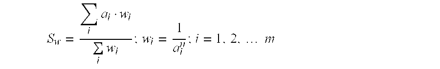
where:
m=the total number of offsets,
a=input real amplitudes,
w=inverse power weights,
Sw=inverse power weighted stack, and
i=ith sample.
n=nth power.
Of course, any other method of stacking such as median stack, and trimmed stack, to name just a few, will occur to those of ordinary skill in the art. Next, each of the three stacks is centered at the middle of the minimum and maximum offset in each set of amplitudes. The results are three model amplitudes for each time slice.
In a further embodiment, at block 28, representative offset values are determined for each set. The three model amplitudes, for example, S1, S2, and S3, have three corresponding representative offsets, x1, x2, and x3, respectively. These offsets are centered at each selected amplitude set. For example, in some embodiments, each representative offset value is the average of the minimum and maximum offsets in the selected set.
In still an even further embodiment, at block 30, the representative offsets are transformed to the sine square of the angle of incidence domain using the offset value (x), the normal incidence travel time (t0), and the average or root mean square (RMS) velocity (V) to t0, by the following relationship: 
Of course, in alternate embodiments, representative offsets are transformed to the square offsets, square tangents of the angle of incidence, or any other domain which will occur to those of ordinary skill in the art.
In still a further embodiment, at block 32, a parabola is fitted to the model amplitudes. Using the three model amplitudes a parabola is fitted 32 versus the sin2(θ). The parabolic model is characterized by the following equation:
The parabolic fitting produces three coefficients: b0, b1, and b2. Of course, in an even further embodiment, any other coefficients produced from a different shaped fitting are used.
In still an even further embodiment, at block 33, the originally received offsets of the received seismic data are transformed to the sine square of the angle of incidence domain using the offset value (x), the normal incidence travel time (t0), and the average or root mean square (RMS) velocity (V) to t0, by the following relationship: 
Of course, in alternate embodiments, originally received offsets are transformed to the square offsets, square tangents of the angle of incidence, or any other domain which will occur to those of ordinary skill in the art.
In a further embodiment, at block 34, model amplitudes are now computed at all the transformed originally received offsets for the time slice. Using the coefficients previously computed, model amplitudes at every offset transformed to sin2 θ along the time slice are computed and compared to the real amplitudes at the same offsets transformed to sin2 θ. In an even further embodiment, any other amplitude may be computed and compared as will occur to those of ordinary skill in the art.
In an even further embodiment, at block 36, the difference between the model amplitudes at the transformed originally received offsets and the real amplitudes at the same offset are checked against a predetermined threshold value. If the difference exceeds such threshold value, then the current real amplitude is scaled to match that of the modeled amplitude at block 38 creating edited real amplitudes. The real amplitudes exceeding the threshold value at this point could have been the cause of AGI distortion. In various alternate embodiments, the predetermined threshold is chosen a priori, as a percent of total amplitude, a measure in decibels, or any other predetermined threshold that will occur to those of ordinary skill in the art. The amplitudes are then saved.
In further embodiments, at block 42, the edited real amplitudes at all offsets are used to perform another parabolic model corresponding to the following equation:
The result will be a new set of coefficients which are denominated b′0, b′1, and b′2. In an even further embodiment, the amplitude corresponding to the coefficient value b′0 is the zero offset or predicted amplitude at zero offset without the AGI effect. In a further embodiment, at block 43, the predicted amplitude at zero offset (b′0) is saved for the time slice.
In an even further embodiment, the processed data is reviewed to determine 29 if the time slice being considered is the ith time slice or the last time slice. If the time slice is not the last time slice, the process returns to block 19 and a new time slice is selected. If it is the last time slice, the data may be displayed 60.
Referring now to FIG. 3, a system of the present invention is illustrated in block form. In one embodiment of the present invention, various aspects of the system are in the form of a computer. In alternate embodiments, various aspects will be digital or analog as will occur to one of ordinary skill in the art. Block 112 represents means for receiving. The means for receiving 112 obtains seismic data. In various embodiments of the present invention, means for receiving 112 is a digital computer capable of reading seismic traces from magnetic tape, a computer capable of storing seismic data, or any other means for receiving data that would occur to one of ordinary skill in the art.
In an even further embodiment, block 114 represents a means for raising amplitudes. This means for raising the real amplitude traces 114 converts the data to the nth power by raising the amplitudes of the real traces to the nth power. In various embodiments, means for raising amplitudes 114 is a digital computer, software running on a digital computer, calculator, analog machine, or any other means capable of raising an amplitude to a power that will occur to one of ordinary skill in the art.
In an even further embodiment, means for computing weights 115 is provided. In some embodiments, the means for computing weights 115 further comprises a means for inverting the nth power trace values to obtain weights w. In various embodiments, the means for computing weights 115 is a digital computer, software running on a computer, an analog machine, or any other means that will occur to one of ordinary skill in the art. In alternate embodiments, weights are supplied manually.
In alternate embodiments, a means for smoothing smoothes the weights. In various embodiments, the means for smoothing smoothes the weights with a Boxcar, Bartlett, Gaussian, or other filter that will occur to those of skill in the art. In some embodiments, this filter has a predefined length. Of course, in some embodiments, such smoothing is not needed. In even further embodiments, means for smoothing is a digital computer, software running on a computer, an analog machine, or any other means for smoothing data which will occur to one of ordinary skill in the art.
In an even further embodiment, block 119 represents a means for selecting. A means for selecting 119 selects a time slice and determines the amplitudes of the traces. In various embodiments, means for selecting 119 is a digital computer, software running on a computer, an analog machine, and any other means for selecting 119 which will occur to one of ordinary skill in the art.
In an even further embodiment, block 120 represents a means for scaling. In various embodiments, means for scaling 120 is a digital computer, software running on a computer, an analog machine, and any other means for scaling the amplitudes of seismic data.
In an even further embodiment, block 123, 125 represents a means for stacking. A means for stacking 123, 125 is provided which stacks the real amplitudes and stacks the weights. In various embodiments, the means for stacking 123, 125 is a digital computer, software running on a computer, an analog machine, or any other means for stacking that will occur to one of ordinary skill in the art.
In an even further embodiment, block 127 represents a means for dividing. In various embodiments, means for dividing 127 is a digital computer, software running on a computer, an analog machine, or any other means that will occur to one of ordinary skill in the art.
In an even further embodiment, a means for determining 129 reviews the processed data to determine if the time slice being considered is the ith time slice or the last time slice. If it is the last time slice, the data may be transferred to a display means 160 for displaying the processed data. In various embodiments, means for determining 129 is a digital computer, software running on a computer, an analog machine, or any other means that would occur to one of ordinary skill in the art. In alternate embodiments, means for determining 129 manually compares the time of the time slice to the maximum recording time.
Means for displaying 160 comprises a device such as a monitor or a printout or any other means for displaying 160 that will occur to those of ordinary skill in the art. Of course, the data may be transferred to other methods for further processing as will occur to those of ordinary skill in the art. In various embodiments, means for displaying is a printed seismograph, or any other means for displaying that will occur to those of ordinary skill in the art. If the time slice is not the last time slice, the means for comparing returns the data to means for selecting 119. Means for selecting 119 selects a new time slice, and amplitudes of scaled and weight data are stacked and saved.
Referring now to FIG. 4, a system for effecting various embodiments of the method of the present invention is illustrated in block form. In one embodiment, means for receiving 112 receives seismic data. In one embodiment, means for receiving 112 may be a part of a digital computer, such as a tape reader, or the like which can read data in electronic form and establish values to this data. Of course in alternate embodiments, means for receiving 112 is a digital computer, software running on a computer, an analog machine, or any other means for receiving seismic data that will occur to one of ordinary skill in the art.
In a further embodiment, means for raising amplitudes 114 provides a means for raising the amplitudes to a predetermined nth power. In various embodiments means for raising amplitudes 114 is a digital computer, software running on a computer, an analog machine, or any other means for raising an amplitude to a nth power that will occur to those of ordinary skill in the art. The means for raising 114 converts the input real amplitude traces to nth power values.
In an even further embodiment, the means for creating weights 115 is provided. In a further embodiment, means for computing weights inverts the nth power traces to obtain the weights w. In various embodiments, means for computing weights 115 is a digital computer, software running on a computer, an analog machine, or any other means for computing weights or inverting seismic data that will occur to one of ordinary skill in the art.
In alternate embodiments, a means for smoothing is provided. Means for smoothing smoothes the nth power values or weights. In alternate embodiments, means for smoothing is a Boxcar, Bartlett, or Gaussian filter. This filter will have a predefined length in some embodiments. Of course other means for smoothing such as a digital computer, software running on a computer, an analog machine, will also occur to one of ordinary skill in the art as well as many others.
In a further embodiment, means for selecting 119 selects a time slice and determines the amplitudes. In various embodiments, means for selecting 119 is a digital computer, software running on a computer, an analog machine, or any other means for selecting that will occur to one of ordinary skill in the art.
In a further embodiment, means for scaling 120 scales amplitudes. In various embodiments, means for scaling 120 scales real amplitudes, or any other data that will occur to those of ordinary skill in the art. In various embodiments, means for scaling 120 is a digital computer, software running on a computer, an analog machine, or any other means for selecting that will occur to one of ordinary skill in the art.
In an even further embodiment, a means for dividing amplitudes into sets 121 divides the amplitudes of the time slice into sets. Means 121 divides both the weights and the scaled data into sets. The means for dividing into sets 121 is a digital computer, software running on a computer, an analog machine, or any other means that will occur to those of ordinary skill in the art. In a further alternate embodiment, the sets are divided manually.
In an even further embodiment, a means for stacking 122 stacks the amplitudes of each set of the time slice of the weights and scaled data. In alternate embodiments, means for stacking 122 will stack the data in a digital computer, software running on a computer, an analog machine, or any other method that will occur to those of ordinary skill in the art.
In an even further embodiment, a means for developing a model amplitude 126 develops model amplitudes corresponding to each set. In one example embodiment, the means for developing 126 centers each of the three weighted stacks at the middle of the minimum and maximum offset included in each set of amplitudes. The results of the means for developing 126 are three model amplitudes for each time slice. In various embodiments, the means for developing 126 is a digital computer, software running on a computer, an analog machine, or any other means 126 of developing model amplitudes that will occur to one of ordinary skill in the art.
A means for determining the center of offset values 128 determines representative offset values. The three model amplitudes, for example, s1, s2 and s3, will have three corresponding representative offsets, x1, x2 and x3, respectively. For example, in one embodiment, each offset value is the average of the minimum and maximum offsets in the selected set.
In a further embodiment, a means for transforming the representative offset values 130, transforms the representative offsets to the sine square of the angle of incidence domain. In various embodiments, means for transforming 130 is a digital computer, software running on a computer, an analog machine, or any other means that will occur to those of ordinary skill in the art.
In an even further embodiment, a means for fitting a parabola 132 fits a parabola to the transformed representative offset values for the selected data sets. In various embodiments, means for fitting a parabola 132 is a digital computer, software running on a computer, an analog machine, or any other means that will occur to those of ordinary skill in the art.
In a further embodiment, a means for transforming 133 the originally received offset values of the received seismic data, transforms the originally received offsets to the sine square of the angle of incidence domain. In various embodiments, means for transforming 133 is a digital computer, software running on a computer, an analog machine, or any other means that will occur to those of ordinary skill in the art.
In an even further embodiment, a means for computing model amplitudes 134 is provided. Model amplitudes are computed at all the transformed originally received offsets for the time slice. In various embodiments, the means for computing 134 is a digital computer, software running on a computer, an analog machine, or any other means for computing an amplitude that will occur to one of ordinary skill in the art.
In an even further embodiment, means for comparing 136 the difference between the model amplitudes and the real or raw amplitudes is provided. Means 136 compares this difference with a a predetermined threshold value. In various embodiments, the means for comparing 136 is a digital computer, software running on a computer, an analog machine, or any other means for comparing that will occur to one of ordinary skill in the art.
In an even further embodiment, means for scaling 138 is provided. If the difference exceeds such threshold value, then the current real amplitude is scaled to match that of the modeled amplitude. This creates edited amplitudes. In various embodiments, means for scaling 138 is a digital computer, software running on a computer, an analog machine, or any other means that will occur to one of ordinary skill in the art.
In an even further embodiment, means for fitting a parabola to all the transformed originally received offsets 142 performs another parabolic fitting to the scaled amplitudes. The result will be a new set of coefficients which are denominated b′0, b′1, and b′2. b′0 is then the current predicted amplitude at zero offset with no AGI effect. It is saved by a memory saving means 143. In various embodiments, means for saving 143 is a digital computer, software running on a computer, an analog machine, or any other means that will occur to one of ordinary skill in the art.
In a further embodiment, means for determining 129 reviews the processed data to determine if the time slice being considered is the ith time slice or the last time slice. If the time slice is not the last time slice, the system returns to means for selecting 119 and a new time slice is selected. If it is the last time slice, the data is displayed by display means 160. In alternate embodiments, means for displaying 160 is a digital computer, software running on a computer, an analog machine, or any other means that will occur to those of ordinary skill in the art.
While example embodiments of the present invention have been illustrated and described, it will be appreciated that numerous changes and modifications will occur to those skilled in the art, and it is intended in the appended claims to cover all those changes and modifications which fall within the true spirit and scope of the present invention.
Claims (74)
1. A method for attenuation of acquisition geometry imprint in seismic data comprising:
raising amplitudes of said seismic data to a predetermined power;
computing weights;
selecting a time slice of the seismic data and said weights;
scaling the seismic data with the weights;
stacking the scaled data;
stacking the weights; and
dividing the stacked scaled data by the stacked weights.
2. The method of claim 1 , wherein said computing weights further comprises inverting the seismic data.
3. The method of claim 1 , wherein said scaling, stacking, and dividing further comprises stacking with an inverse nth power weighted stack.
4. The method of claim 3 , wherein said inverse nth power weighted stack comprises: 
wherein:
m comprises a number of offsets;
a comprises an input real amplitudes from said receiving seismic data;
w comprises a weight;
i comprises a sample; and
n comprises a predetermined power.
5. The method of claim 1 , further comprising smoothing said weights.
6. The method of claim 5 , wherein said smoothing further comprises filtering.
7. The method of claim 6 , wherein said filtering further comprises filtering with a Boxcar filter.
8. The method of claim 6 , wherein said filtering further comprises filtering with a Bartlett filter.
9. The method of claim 6 , wherein said filtering further comprises filtering with a Gaussian filter.
10. The method of claim 1 , wherein said raising amplitudes further comprises squaring said amplitudes.
11. The method of claim 1 , wherein said receiving further comprises obtaining common midpoint gathers.
12. The method of claim 1 , further comprising displaying the seismic data.
13. The method of claim 12 , wherein said displaying further comprises displaying data on a monitor.
14. The method of claim 12 , wherein said displaying further comprises printing a seismogram.
15. The method of claim 1 , further comprising determining if the time slice selected is the last time slice.
16. A method for attenuation of acquisition geometry imprint in seismic data comprising:
receiving seismic data;
raising amplitudes of said seismic data to a predetermined power;
computing weights;
selecting a time slice of said seismic data and said weights;
scaling the seismic data with the weights;
dividing amplitudes of said time slice of the scaled data and the weights into sets;
stacking the amplitudes of each set of the scaled data and the weights;
developing a model amplitude corresponding to each set;
determining representative offset values for each set;
transforming the representative offset values for each set;
fitting a parabola to the transformed representative offset values and modeled amplitudes for each time slice;
transforming originally received offsets of the received seismic data;
computing model amplitudes at the transformed originally received offsets;
comparing the difference between the seismic data and the model amplitudes at the transformed originally received offsets to a predetermined threshold;
scaling the seismic data to match said model amplitudes whenever amplitudes of the seismic data exceed said predetermined threshold creating edited real amplitudes; and
fitting a parabola to said transformed originally received offsets and the edited amplitudes.
17. The method of claim 16 , further comprising saving predicted amplitude at zero offset.
18. The method of claim 16 , wherein said developing a model amplitude corresponding to each set further comprises dividing the stacked scaled data by the stacked weights.
19. The method of claim 18 , wherein said developing further comprises stacking with an inverse nth power weighted stack.
20. The method of claim 19 , wherein said inverse nth power weighted stack comprises: 
wherein:
m comprises a number of offsets;
a comprises an input real amplitudes from said receiving seismic data;
w comprises a weight;
i comprises a sample; and
n comprises a predetermined power.
21. The method of claim 16 , further comprising displaying the seismic data.
22. The method of claim 21 , wherein said displaying further comprises displaying said data on a monitor.
23. The method of claim 21 , wherein said displaying further comprises printing a seismogram.
24. The method of claim 16 , wherein said receiving further comprises obtaining common midpoint gathers.
25. The method of claim 16 , wherein said raising amplitudes of said seismic data to a predetermined power further comprises raising said amplitudes to the first power.
26. The method of claim 16 , wherein said raising amplitudes of said seismic data to a predetermined power further comprises squaring said amplitudes.
27. The method of claim 16 , wherein said transforming said representative offset values further comprises transforming said offset values to a sine square of the angle of incidence domain.
28. The method of claim 27 , wherein said transforming said representative offset values to a sine square of the angle of incidence domain further comprises: 
wherein:
x comprises an offset value;
t0 comprises a normal incidence travel time;
V comprises a velocity; and
θ comprises an angle of incidence.
29. The method of claim 16 , wherein said transforming said originally received offset values further comprises transforming said offset values to a sine square of the angle of incidence domain.
30. The method of claim 29 , wherein said transforming said originally received offset values to a sine square of the angle of incidence domain further comprises: 
wherein:
x comprises an offset value;
t0 comprises a normal incidence travel time;
V comprises a velocity; and
θ comprises an angle of incidence.
31. The method of claim 16 , wherein said fitting a parabola further comprises:
wherein:
θ comprises an angle of incidence; and
b0, b1, and b2 comprise coefficients.
32. The method of claim 27 , wherein said fitting a parabola further comprises:
wherein:
θ comprises an angle of incidence; and
b′ 0, b′1, and b′2 comprise coefficients.
33. The method of claim 29 , wherein said fitting a parabola further comprises:
wherein:
θ comprises an angle of incidence; and
b′0, b′1, and b′2 comprise coefficients.
34. The method of claim 16 , wherein said computing weights further comprises inverting the seismic data.
35. The method of claim 16 , further comprising smoothing the weights.
36. The method of claim 35 , wherein said smoothing further comprises filtering.
37. The method of claim 36 , wherein said filtering comprises filtering with a Boxcar filter.
38. The method of claim 36 , wherein said filtering comprises filtering with a Bartlett filter.
39. The method of claim 36 , wherein said filtering comprises filtering with a Gaussian filter.
40. The method of claim 16 , wherein said saving the scaled amplitudes further comprises saving the scaled amplitudes for all offsets at the time slice.
41. The method of claim 16 , further comprising determining if the time slice selected is the last time slice.
42. A system for attenuation of acquisition geometry imprint in seismic data comprising:
means for raising amplitudes of said seismic data to a predetermined power;
means for computing weights;
means for selecting a time slice of the seismic data and said weights;
means for scaling the received seismic data with the weights;
means for stacking the scaled data;
means for stacking the weights; and
means for dividing the stacked scaled data by the stacked weights.
43. The system of claim 42 , wherein said means for computing weights further comprises means for inverting the seismic data.
44. The system of claim 42 , wherein said means for scaling, means for stacking, and means for dividing further comprises means for stacking with an inverse nth power weighted stack.
45. The system of claim 42 , further comprising means for smoothing said weights.
46. The system of claim 45 , wherein said means for smoothing further comprises a filter.
47. The system of claim 46 , wherein said filter further comprises a Boxcar filter.
48. The system of claim 46 , wherein said filter further comprises filtering with a Bartlett filter.
49. The system of claim 46 , wherein said filtering further comprises a Gaussian filter.
50. The system of claim 42 , wherein said means for raising amplitudes further comprises means for squaring said amplitudes.
51. The system of claim 42 , wherein said means for receiving further comprises means for obtaining common midpoint gathers.
52. The system of claim 42 , further comprising means for displaying the seismic data.
53. The system of claim 52 , wherein said means for displaying further comprises a monitor.
54. The system of claim 52 , wherein said means for displaying further comprises a seismogram.
55. The system of claim 52 , further comprising means for determining if the time slice selected is the last time slice.
56. A system for attenuation of acquisition geometry imprint in seismic data comprising:
means for receiving seismic data;
means for raising amplitudes of said seismic data to a predetermined power;
means for computing weights;
means for selecting a time slice of said seismic data and said weights;
means for scaling the seismic data with the weights;
means for dividing amplitudes of said time slice of the scaled data and the weights into sets;
means for stacking the amplitudes of each set of the scaled data and the weights;
means for developing a model amplitude corresponding to each set;
means for determining representative offset values for each set;
means for transforming the representative offset values for each set;
means for fitting a parabola to the transformed representative offset values and modeled amplitudes for each time slice;
means for transforming originally received offsets of the received seismic data;
means for computing model amplitudes at the transformed originally received offsets;
means for comparing the difference between the seismic data and the model amplitudes at the transformed originally received offsets to a predetermined threshold;
means for scaling the seismic data to match said model amplitudes whenever amplitudes of seismic data exceed said predetermined threshold creating edited real amplitudes; and
means for fitting a parabola to said transformed originally received offsets and the edited amplitudes.
57. The system of claim 56 , further comprising means for means for saving predicted amplitude at zero offset.
58. The system of claim 56 , wherein said means for developing a model amplitude corresponding to each set further comprises means for dividing the stacked scaled data by the stacked weights.
59. The system of claim 58 , wherein said means for developing further comprises means for stacking with an inverse nth power weighted stack.
60. The system of claim 56 , further comprising means for displaying the seismic data.
61. The system of claim 60 , wherein said means for displaying further comprises means for visually reviewing said data.
62. The system of claim 60 , wherein said means for displaying further comprises means for printing a seismogram.
63. The system of claim 60 , wherein said means for receiving further comprises means for obtaining common midpoint gathers.
64. The system of claim 56 , wherein said means for raising amplitudes of said seismic data to a predetermined power further comprises means for squaring said amplitudes.
65. The system of claim 56 , wherein said means for transforming said representative offset values further comprises means for transforming said representative offset values to a sine square of the angle of incidence domain.
66. The system of claim 56 , wherein said means for transforming said originally received offset values further comprises means for transforming said originally received offset values to a sine square of the angle of incidence domain.
67. The system of claim 56 , wherein said means for computing weights further comprises means for inverting the seismic data.
68. The system of claim 56 , further comprising means for smoothing the weights.
69. The system of claim 68 , wherein said means for smoothing further comprises a filter.
70. The system of claim 69 , wherein said filter comprises a Boxcar filter.
71. The system of claim 69 , wherein said filter comprises a Bartlett filter.
72. The system of claim 69 , wherein said filter comprises a Gaussian filter.
73. The system of claim 56 , wherein said means for saving the scaled amplitudes further comprises means for saving the scaled amplitudes for all offsets at the time slice.
74. The system of claim 56 , further comprising means for determining if the time slice selected is the last time slice.
Priority Applications (7)
| Application Number | Priority Date | Filing Date | Title |
|---|---|---|---|
| US09/658,057 US6463388B1 (en) | 2000-09-08 | 2000-09-08 | Method and system for attenuation of acquisition geometry imprint in seismic data |
| PCT/US2001/041398 WO2002021159A2 (en) | 2000-09-08 | 2001-07-24 | Method and system for attenuation of acquisition geometry imprint in seismic data |
| AU81336/01A AU782546B2 (en) | 2000-09-08 | 2001-07-24 | Method and system for attenuation of acquisition geometry imprint in seismic data |
| GB0211803A GB2372570B (en) | 2000-09-08 | 2001-07-24 | Method and system for attenuation of acquisition geometry imprint in seismic data |
| EG20010956A EG22829A (en) | 2000-09-08 | 2001-09-04 | Method and system for attenuation of acquisition geometry imprint in seismic data |
| NO20022043A NO20022043L (en) | 2000-09-08 | 2002-04-30 | Method and system for attenuating the reflection geometry of seismic data |
| AU2005202807A AU2005202807B2 (en) | 2000-09-08 | 2005-06-27 | Method and system for attenuation of acquisition geometry imprint in seismic data |
Applications Claiming Priority (1)
| Application Number | Priority Date | Filing Date | Title |
|---|---|---|---|
| US09/658,057 US6463388B1 (en) | 2000-09-08 | 2000-09-08 | Method and system for attenuation of acquisition geometry imprint in seismic data |
Publications (1)
| Publication Number | Publication Date |
|---|---|
| US6463388B1 true US6463388B1 (en) | 2002-10-08 |
Family
ID=24639731
Family Applications (1)
| Application Number | Title | Priority Date | Filing Date |
|---|---|---|---|
| US09/658,057 Expired - Fee Related US6463388B1 (en) | 2000-09-08 | 2000-09-08 | Method and system for attenuation of acquisition geometry imprint in seismic data |
Country Status (6)
| Country | Link |
|---|---|
| US (1) | US6463388B1 (en) |
| AU (1) | AU782546B2 (en) |
| EG (1) | EG22829A (en) |
| GB (1) | GB2372570B (en) |
| NO (1) | NO20022043L (en) |
| WO (1) | WO2002021159A2 (en) |
Cited By (5)
| Publication number | Priority date | Publication date | Assignee | Title |
|---|---|---|---|---|
| US6675102B1 (en) * | 2002-09-13 | 2004-01-06 | Seismic Micro-Technology, Inc. | Method of processing seismic geophysical data to produce time, structure, volumes |
| US20040233782A1 (en) * | 2003-05-20 | 2004-11-25 | Chevron U.S.A. Inc. | Method for signal-to-noise ratio enhancement of seismic data using frequency dependent true relative amplitude noise attenuation |
| US20050027454A1 (en) * | 2003-07-30 | 2005-02-03 | Vaage Svein Torleif | Method for separating seismic signals from two or more distinct sources |
| US20160370484A1 (en) * | 2014-03-05 | 2016-12-22 | Cgg Services Sa | Systems and methods to reduce noise in seismic data using a frequency dependent calendar filter |
| US9651695B2 (en) | 2013-09-19 | 2017-05-16 | Pgs Geophysical As | Construction and application of angle gathers from three-dimensional imaging of multiples wavefields |
Families Citing this family (4)
| Publication number | Priority date | Publication date | Assignee | Title |
|---|---|---|---|---|
| CN102707317B (en) * | 2010-10-27 | 2014-08-06 | 中国石油化工股份有限公司 | Method of using absorption and attenuation characteristics of seismic wave for reservoir analysis |
| CN102736124B (en) * | 2012-06-14 | 2014-03-19 | 北京市市政工程研究院 | Tunnel excavation surrounding rock dynamic refined classification method based on integrated parameters |
| CN102809762B (en) * | 2012-08-13 | 2014-09-03 | 成都理工大学 | Reservoir imaging technique based on full-frequency-band seismic information mining |
| US9310504B2 (en) | 2013-02-01 | 2016-04-12 | Pgs Geophysical As | Systems and methods for detecting swell noise in a seismic gather |
Citations (3)
| Publication number | Priority date | Publication date | Assignee | Title |
|---|---|---|---|---|
| US3398396A (en) | 1966-06-13 | 1968-08-20 | Texas Instruments Inc | Diversity seismic record stacking method and system |
| US6151555A (en) * | 1999-03-09 | 2000-11-21 | Schlumberger Technology Corporation | Seismic signal processing method and apparatus for generating a cube of variance values |
| US6343256B1 (en) * | 2000-06-12 | 2002-01-29 | Exxonmobil Upstream Research Company | Illumination corrections to reduce geometrical artifacts in seismic data |
Family Cites Families (4)
| Publication number | Priority date | Publication date | Assignee | Title |
|---|---|---|---|---|
| US4561074A (en) * | 1982-12-29 | 1985-12-24 | Amoco Corporation | Computationally efficient weighting and vertical stacking methods and apparatus for improving signal-to-noise ratio of seismic data |
| US4905204A (en) * | 1988-09-06 | 1990-02-27 | Exxon Production Research Company | Method of weighting a trace stack from a plurality of input traces |
| US5684754A (en) * | 1995-12-13 | 1997-11-04 | Atlantic Richfield Company | Method and system for correcting seismic traces for normal move-out stretch effects |
| US6131071A (en) * | 1996-12-06 | 2000-10-10 | Bp Amoco Corporation | Spectral decomposition for seismic interpretation |
-
2000
- 2000-09-08 US US09/658,057 patent/US6463388B1/en not_active Expired - Fee Related
-
2001
- 2001-07-24 AU AU81336/01A patent/AU782546B2/en not_active Ceased
- 2001-07-24 GB GB0211803A patent/GB2372570B/en not_active Expired - Fee Related
- 2001-07-24 WO PCT/US2001/041398 patent/WO2002021159A2/en active IP Right Grant
- 2001-09-04 EG EG20010956A patent/EG22829A/en active
-
2002
- 2002-04-30 NO NO20022043A patent/NO20022043L/en not_active Application Discontinuation
Patent Citations (3)
| Publication number | Priority date | Publication date | Assignee | Title |
|---|---|---|---|---|
| US3398396A (en) | 1966-06-13 | 1968-08-20 | Texas Instruments Inc | Diversity seismic record stacking method and system |
| US6151555A (en) * | 1999-03-09 | 2000-11-21 | Schlumberger Technology Corporation | Seismic signal processing method and apparatus for generating a cube of variance values |
| US6343256B1 (en) * | 2000-06-12 | 2002-01-29 | Exxonmobil Upstream Research Company | Illumination corrections to reduce geometrical artifacts in seismic data |
Non-Patent Citations (2)
| Title |
|---|
| Gulunay, et al., "3D Data Acquisition Artifacts Removal-Spot Editing in the Spatial-Temporal Frequency Domain", 56th Meeting and Technical Exhibition, Vienna, Austria, Jun. 6-10, 1994. |
| Hill, et al., "Acquisition Footprint and fold-of-stack plots", The Leading Edge, Jun. 1999, pp. 686-695. |
Cited By (7)
| Publication number | Priority date | Publication date | Assignee | Title |
|---|---|---|---|---|
| US6675102B1 (en) * | 2002-09-13 | 2004-01-06 | Seismic Micro-Technology, Inc. | Method of processing seismic geophysical data to produce time, structure, volumes |
| US20040233782A1 (en) * | 2003-05-20 | 2004-11-25 | Chevron U.S.A. Inc. | Method for signal-to-noise ratio enhancement of seismic data using frequency dependent true relative amplitude noise attenuation |
| US6950371B2 (en) * | 2003-05-20 | 2005-09-27 | Chevron U.S.A. Inc. | Method for signal-to-noise ratio enhancement of seismic data using frequency dependent true relative amplitude noise attenuation |
| US20050027454A1 (en) * | 2003-07-30 | 2005-02-03 | Vaage Svein Torleif | Method for separating seismic signals from two or more distinct sources |
| US6882938B2 (en) | 2003-07-30 | 2005-04-19 | Pgs Americas, Inc. | Method for separating seismic signals from two or more distinct sources |
| US9651695B2 (en) | 2013-09-19 | 2017-05-16 | Pgs Geophysical As | Construction and application of angle gathers from three-dimensional imaging of multiples wavefields |
| US20160370484A1 (en) * | 2014-03-05 | 2016-12-22 | Cgg Services Sa | Systems and methods to reduce noise in seismic data using a frequency dependent calendar filter |
Also Published As
| Publication number | Publication date |
|---|---|
| NO20022043D0 (en) | 2002-04-30 |
| WO2002021159A3 (en) | 2003-02-06 |
| GB0211803D0 (en) | 2002-07-03 |
| GB2372570A (en) | 2002-08-28 |
| AU8133601A (en) | 2002-03-22 |
| NO20022043L (en) | 2002-06-20 |
| WO2002021159A2 (en) | 2002-03-14 |
| GB2372570B (en) | 2004-08-25 |
| AU782546B2 (en) | 2005-08-11 |
| EG22829A (en) | 2003-09-30 |
Similar Documents
| Publication | Publication Date | Title |
|---|---|---|
| US6631325B1 (en) | Computer implemented empirical mode decomposition method apparatus, and article of manufacture utilizing curvature extrema | |
| RU2300123C2 (en) | Radon's transformation of high resolution for processing of seismic data | |
| US8873333B2 (en) | Geophysical signal processing | |
| US20080170468A1 (en) | Method for Processing at Least Two Sets of Seismic Data | |
| Duncan et al. | Median filter behaviour with seismic data1 | |
| CN109254324B (en) | Full-frequency amplitude-preserving seismic data processing method and device | |
| US6950371B2 (en) | Method for signal-to-noise ratio enhancement of seismic data using frequency dependent true relative amplitude noise attenuation | |
| US6463388B1 (en) | Method and system for attenuation of acquisition geometry imprint in seismic data | |
| CN104502965A (en) | Retrieving method for amplitude compensation factor | |
| Bindi et al. | Local and duration magnitudes in northwestern Italy, and seismic moment versus magnitude relationships | |
| US7447114B2 (en) | Non-linear seismic trace matching to well logs | |
| Duncan et al. | Some analyses of 2-D median fk filters | |
| CN109613531A (en) | Multi-threshold optimization deformation inversion method and system for micro-variation perception early warning radar | |
| EP3101573B1 (en) | Deconvolution method for emissions measurement | |
| US20030225541A1 (en) | Intelligent test point selection for bit error rate tester-based diagrams | |
| CN106706285A (en) | Brake disc inherent frequency online detection method | |
| US20090080287A1 (en) | Method for Estimating Absorption Parameter Q(T) | |
| US6182015B1 (en) | High fidelity rotation method and system | |
| AU2005202807B2 (en) | Method and system for attenuation of acquisition geometry imprint in seismic data | |
| GB2174809A (en) | A method of seismic record processing to distinguish elastic from anelastic formation properties | |
| Saar et al. | Multiscale morphology of the galaxy distribution | |
| US6049757A (en) | Parametric modeling of well log data to remove periodic errors | |
| US20100049441A1 (en) | Method of locating a magnetic object, and the corresponding computer program product, storage means and location device | |
| Scholte | Fourier based high-resolution near-field sound imaging | |
| Sayeed et al. | Optimal quadratic detection and estimation using generalized joint signal representations |
Legal Events
| Date | Code | Title | Description |
|---|---|---|---|
| AS | Assignment |
Owner name: PGS AMERICAS, INC., TEXAS Free format text: ASSIGNMENT OF ASSIGNORS INTEREST;ASSIGNOR:MARTINEZ, RUBEN;REEL/FRAME:011095/0921 Effective date: 20000907 |
|
| FPAY | Fee payment |
Year of fee payment: 4 |
|
| REMI | Maintenance fee reminder mailed | ||
| LAPS | Lapse for failure to pay maintenance fees | ||
| STCH | Information on status: patent discontinuation |
Free format text: PATENT EXPIRED DUE TO NONPAYMENT OF MAINTENANCE FEES UNDER 37 CFR 1.362 |
|
| FP | Lapsed due to failure to pay maintenance fee |
Effective date: 20101008 |