US6450474B1 - X-configuration engine mounting with locking end plates - Google Patents
X-configuration engine mounting with locking end plates Download PDFInfo
- Publication number
- US6450474B1 US6450474B1 US09/522,458 US52245800A US6450474B1 US 6450474 B1 US6450474 B1 US 6450474B1 US 52245800 A US52245800 A US 52245800A US 6450474 B1 US6450474 B1 US 6450474B1
- Authority
- US
- United States
- Prior art keywords
- mount
- facing surfaces
- inwardly
- outer member
- outwardly facing
- Prior art date
- Legal status (The legal status is an assumption and is not a legal conclusion. Google has not performed a legal analysis and makes no representation as to the accuracy of the status listed.)
- Expired - Lifetime
Links
Images


Classifications
-
- F—MECHANICAL ENGINEERING; LIGHTING; HEATING; WEAPONS; BLASTING
- F16—ENGINEERING ELEMENTS AND UNITS; GENERAL MEASURES FOR PRODUCING AND MAINTAINING EFFECTIVE FUNCTIONING OF MACHINES OR INSTALLATIONS; THERMAL INSULATION IN GENERAL
- F16F—SPRINGS; SHOCK-ABSORBERS; MEANS FOR DAMPING VIBRATION
- F16F1/00—Springs
- F16F1/36—Springs made of rubber or other material having high internal friction, e.g. thermoplastic elastomers
- F16F1/38—Springs made of rubber or other material having high internal friction, e.g. thermoplastic elastomers with a sleeve of elastic material between a rigid outer sleeve and a rigid inner sleeve or pin, i.e. bushing-type
- F16F1/387—Springs made of rubber or other material having high internal friction, e.g. thermoplastic elastomers with a sleeve of elastic material between a rigid outer sleeve and a rigid inner sleeve or pin, i.e. bushing-type comprising means for modifying the rigidity in particular directions
-
- B—PERFORMING OPERATIONS; TRANSPORTING
- B60—VEHICLES IN GENERAL
- B60K—ARRANGEMENT OR MOUNTING OF PROPULSION UNITS OR OF TRANSMISSIONS IN VEHICLES; ARRANGEMENT OR MOUNTING OF PLURAL DIVERSE PRIME-MOVERS IN VEHICLES; AUXILIARY DRIVES FOR VEHICLES; INSTRUMENTATION OR DASHBOARDS FOR VEHICLES; ARRANGEMENTS IN CONNECTION WITH COOLING, AIR INTAKE, GAS EXHAUST OR FUEL SUPPLY OF PROPULSION UNITS IN VEHICLES
- B60K5/00—Arrangement or mounting of internal-combustion or jet-propulsion units
- B60K5/12—Arrangement of engine supports
- B60K5/1208—Resilient supports
Definitions
- the present invention is directed to an elastomeric mount of the type used to support and isolate an engine from a vehicle chassis. More particularly the present invention is directed to a mount which has four preferably inclined elastomeric elements, each of which is simultaneously preloaded in compression and shear.
- elastomeric mounts In applications involving on- and off-highway equipment, elastomeric mounts must be rugged to take the pounding from traversing unimproved roads. In addition, these mounts should be designed to avoid total disconnect of the power train from the support in the event of elastomer failure (i.e., they are safetied). Finally, the provision of snubbing in all three orthogonal directions protects the power train, improves subjective ride quality and reduces unwanted chatter caused by metal-to-metal contact.
- the mount of the present invention provides a safetied design that uses four preferably inclined elastomeric elements which are formed by spaced laterally extending compartments, and the elastomeric elements preferably being mechanically locked or bonded to four outwardly facing faces of an inner member and to the four opposing inwardly facing faces of an outer member. Even should the elastomeric elements all fail, the inner member will be retained within the outer member. In several of the described embodiments, either of the inner or outer member are bifurcated into separate elements and, in preassembled condition, the elements are spaced such that opposed mating surfaces of the upper and lower elements are non-engaging.
- the two mating surfaces are brought together, preferably into engaging contact resulting in each of the elastomeric components experiencing preloading in both the compressive and shear directions.
- the inner and outer members are each one element, and the elastomeric components are bonded between parallel plates and preloaded between the opposing faces of the members. This preload results in superior wear life of the elastomeric elements.
- Snubbing is preferably provided in each of the two vertical and the fore/aft (not lateral) directions to eliminate metal-to-metal contact and resulting mechanical chatter.
- the opposing surfaces of the inner and outer members are designed to be non-planar in order to increase the stiffness of the mount in a lateral direction.
- auxiliary lateral elements are used. This increase in spring rate raises the natural frequency of the mounting system out of an undesirable frequency range defined by the vehicle structure.
- the bifurcated elements of the outer member interengage to maintain the mount in its assembled condition prior to installation.
- chevron-shaped elastic assemblies are each formed in an X-configuration as separate elastomeric elements bonded between parallel edge plates for maximizing mold capacity, and for reducing manufacturing cost. Precompression of the elastic assemblies between the inner and outer members serves to increase load-carrying capacity.
- Another embodiment is provided in which retaining plates on opposite faces of the elastomeric elements are formed with turned-out ends which grip respective adjacent edges of the inner and outer members.
- An alternative configuration of the outer member is also provided whereby the loading on each bolt attaching the outer member to a support structure is more in tension than in bending.
- FIG. 1A is a cross-sectional front view of a first embodiment of the mount of the present invention.
- FIG. 1B is a cross-sectional side view of the first embodiment taken along line 1 B— 1 B as seen in FIG. 1 A.
- FIG. 1C is a cross-sectional front view of the first embodiment of the mount shown in the pre-installed condition.
- FIG. 1D is cross-sectional side view of one elastomeric component of the mount of the present invention as seen along line 1 D— 1 D in FIG. IC.
- FIG. 2A is front view of a second embodiment of mount.
- FIG. 2B is a cross-sectional side view of the second embodiment as seen along line 2 B— 2 B in FIG. 2 A.
- FIG. 2C is a top view of the second embodiment of mount.
- FIG. 2D is a back view of the second embodiment of the mount of the present invention shown in pre-installed condition.
- FIG. 3A is a front view of an upper portion of the bifurcated outer member of the mount of a third embodiment of the mount.
- FIG. 3B is an enlarged cross-sectional side view of a portion of the outer member as seen along line 3 B— 3 B in FIG. 3A;
- FIG. 3C is a front view of the inner member of the third embodiment of the mount.
- FIG. 3D is an enlarged cross-sectional side view of a portion of the inner member as seen along line 3 D— 3 D of FIG. 3 C.
- FIG. 3E is an enlarged cross-sectional side view of the third embodiment of the mount showing the nonplanar opposing pairs of surfaces.
- FIG. 3F is a cross-sectional side view of a third nonplanar modification to the third embodiment of the mount.
- FIG. 3G is a cross-sectional side view of a lateral stiffness modification to the third embodiment of mount.
- FIG. 3H is a cross-sectional side view of a second lateral stiffness modification to the third embodiment of the present invention.
- FIG. 4A is a front view of a fourth embodiment of the mount with a bifurcated inner member.
- FIG. 4B is a front view of a fifth embodiment of the mount of the present invention similar to the fourth embodiment.
- FIG. 5A is a front view of a sixth embodiment of the mount.
- FIG. 5B is a cross-sectioned side view of the sixth embodiment along a section line 5 B— 5 B shown in FIG. 5 A.
- FIG. 5C is a front view of a sixth embodiment of the mount shown in a preassembled condition.
- FIG. 6A is a front view of a seventh embodiment of the mount.
- FIG. 6B is a top view of the seventh embodiment of the mount.
- FIG. 6C is a side view of the seventh embodiment of the mount.
- FIG. 7A is an front view of an eighth embodiment of the mount.
- FIG. 7B is a cross-sectional side view of an eighth embodiment of the mount along the section line 7 B— 7 B shown in FIG. 7 A.
- FIG. 8A is a pictorial representation of a ninth embodiment of the mount as assembled in a preloaded condition
- FIG. 8B is a front view, partially in vertical cross section of the mount of FIG. 8 A.
- FIG. 8C is a top view of the mount.
- FIG. 8D is a view in cross section of the mount taken in a plane along the line 8 D— 8 D of FIG. 8 B.
- FIG. 8E is a view in cross section of an elastomeric element in the mount taken in a plane along the line 8 E— 8 E of FIG. 8B;
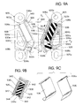
- FIG. 9A is a front view, partly in vertical cross section, of a tenth embodiment according to the invention, similar to the ninth embodiment but with modified elastic assemblies and inner and outer members.
- FIG. 9B a partial cross-sectional view of the mount of FIG. 9A taken in a plane along the line 9 B— 9 B.
- FIG. 9C is an isometric view of opposed retainer plates in the elastic assemblies of FIG. 9 A.
- FIG. 9D is a perspective view of an outer member of the engine mount of FIG. 9 A.
- FIG. 10A is a view of an alternate configuration of the outer member of FIG. 9 A.
- FIG. 10B is a side view of the outer member of FIG. 10 A.
- FIG. 10C is a perspective view of the outer member of FIG. 10 A.
- FIGS. 1A-1D A first embodiment of the mount of the present invention is depicted in FIGS. 1A-1D generally at 20 .
- Mount 20 includes outer member 22 , inner member 26 encircled by outer member and an elastomeric element 30 .
- Inner member 26 has four outwardly facing inclined surfaces 28 which oppose four inwardly facing inclined surfaces 24 .
- Elastomeric element 30 is comprised of four preferably interconnected components 32 , one each of which is positioned between and, preferably bonded to, inclined surfaces 24 and 28 .
- outer member 22 is bifurcated into upper element 22 U and lower element 22 L which have first ( 23 U) and second ( 23 L) mating surfaces, respectively.
- Elastomeric components 32 are spaced apart and separated by laterally extending compartments 31 while preferably being interconnected by elastomeric webs 33 a and 33 b .
- Webs 33 a and 33 b offer corrosion inhibiting coating to all otherwise exposed metallic surfaces on the outer ( 22 ) and inner ( 26 ) members with the further advantage of preventing metal-to-metal contact.
- the thicknesses of the elastomeric components 32 are large enough such that the mating surfaces 23 U and 23 L are in non-engaging relationship.
- elastomeric components 32 are simultaneously preloaded in compression and shear to increase the durability of the elastomer (i.e., to extend its wear-life).
- inner member 26 has a pair of notches 34 formed in one end which receive a pair of protrusions 38 extending from one end of an anti-rotation spacer 36 .
- a like pair of protrusions 40 extending from the opposite end of spacer 36 are received in slot openings 44 in an adapter plate 42 which can be bolted to the engine or the support (not shown).
- the mating surfaces 23 U and 23 L are bolted to the other of said engine and said support.
- the inner member 26 will be attached to the engine and the outer member 22 to the support.
- FIG. 1D is a cross-sectional view of the mount shown in FIG. 1C as seen along a section line 1 D— 1 D. Since the static engine load (acting along a direction indicated by arrow A) creates increased compression strain on the lower elastomeric components 32 L, those components will be more critical in providing the desired stiffness control of the mount than upper components 32 U. Generally, a higher stiffness will be required in the lower elastomeric component 32 L than in the upper 32 U to deter drift of the mount 20 . Accordingly, it is an option to lessen the amount of elastomer in upper components 32 U as depicted in FIG. 1D by making the width d 1 of components 32 U unequal to (preferably less than) the width d 2 of lower components 32 L.
- FIGS. 2A-2D A second embodiment of the mount of the present invention is shown in FIGS. 2A-2D generally at 120 .
- This second embodiment of the mount 120 is also a split (bifurcated) outer member design employing upper element 122 U and lower element 122 L. Holes 135 are used to bolt the outer member 122 to the support frame, commonly a truck chassis.
- the inner member 126 is best seen in FIG. 2 B. Compartments 131 are formed by the use of cores in the mold and an intermediate web 133 I interconnects outer web 133 A and inner web 133 B.
- a laterally extending shelf 150 offset from outer member 122 protrudes from the front side of inner member 126 and provides a means for securing mount 120 to the engine (not shown).
- a flange extends from the engine and apertures formed therein receive the bolts 152 . The apertures in the flange may be threaded to receive bolts 152 or the apertures may be through bores and nuts may be used to effect attachment
- Fore-and-aft movement will be snubbed by the engagement of the elastomeric web 133 B encasing inner member 126 with the fore-and-aft inner surfaces of outer member 122 .
- a plurality of elastomeric protrusions 154 are formed on the outward face (away from the engine and toward frame) of inner member 126 and will snub lateral motion against the support frame (whose position is indicated by dotted line B in FIGS. 2 C and 2 B).
- This three axis snubbing prevents mechanical chatter caused by engine vibration during operation and prevents overloading the elastomeric components 132 .
- the variation discussed in connection with the first embodiment of varying the width of the upper elastomeric components 132 relative to the lower ones is applicable to this embodiment and those that follow, as well.
- FIGS. 3A-3E Portions of a third embodiment of the present invention are shown in FIGS. 3A-3E generally at 220 .
- This embodiment affords the desired increase in stiffness by providing the opposing surfaces 224 , 228 on the outer ( 222 ) and inner ( 226 ) members with a non-planar configuration.
- the configuration depicted is a laterally oriented V-shaped although other non-planar configurations, such as arcuate, might also be used.
- the elastomeric element 232 is deformed into a V shape by protrusion 256 and valley 258 .
- non-planar surfaces 224 and 228 will be formed on both upper element 222 U (FIG. 3A) and lower element (not shown) and on inner ( 226 ) member.
- the shear stiffness of elastomeric elements 232 will be increased in the lateral direction transverse to the V.
- FIG. 3F A modification to the third embodiment is shown in FIG. 3F generally at 220 ′.
- an S-shaped protrusion 256 ′ can be employed between outer surface 224 ′ and inner surface 228 ′. This essentially inserts a compressive section 232 C in the lateral direction and enables a larger incremental increase in the stiffness to be added without increasing the stiffness of the elastomer in elastomeric element 232 ′.
- FIGS. 3G and H Second and third modifications to the third embodiment are shown in FIGS. 3G and H, respectively.
- lateral stiffness is added to the mount 220 ′′ by the addition of a separate laterally extending element 253 ′′.
- the laterally extending element 253 ′′ includes an elastomer element 246 ′′ bonded to a plate 245 ′′ which has means for interconnecting to the chassis 11 ′′.
- a threaded bore 248 ′′ in plate 245 ′′ receiving a fastener (not shown) inserted through opening 13 ′′ in chassis 11 ′′.
- a protruding boss 248 ′′′ formed on plate 245 ′′′ that engages in an opening 13 ′′′ in chassis 11 ′′′ may be used.
- use of a fastening bolt is rendered unnecessary by providing an axial preload on the laterally extending element 253 ′′′ thereby precompressing lateral elastomeric element 246 ′′′ when mount 220 ′′′ is bolted to chassis 11 ′′′.
- This preload will provide additional stiffness to the mount in this lateral direction, enabling the mount 220 ′′′ to meet the required stiffness criteria.
- lateral stiffness can be added without having to affect the stiffness of the elastomer used in the precompressed elastomeric elements.
- shelf 250 including bolts 252 attaches to the engine.
- a fourth embodiment is depicted in FIG. 4 A and is identified at 320 .
- the outer member 322 is one piece and inner member 326 is split (bifurcated). Mating surfaces 323 U and 323 L are formed on upper element 326 U and lower element 326 L, of inner member 326 respectively.
- the outer member 322 no longer surrounds the inner member 326 , as was the case in the previous embodiments. Rather, the reacting faces 324 of the outer member 322 are seemingly reversed, such that the surfaces 324 of the outer member are divergent and the actual halves of the inner member no longer form a closed perimeter either but have outwardly directed arms in which surfaces 328 are generally parallel to inwardly directed surfaces 324 .
- the elastomeric components 332 then, too, are reversed so as not to form a closed polygon.
- Four laterally extending compartments 331 afford some room for movement of the inner member 326 relative to the outer member 322 before snubbing occurs.
- Snubbing is provided in all three orthogonal directions.
- FIG. 4 B A fifth embodiment of mount 420 is shown in FIG. 4 B.
- This embodiment also has a split inner member 426 shown here in its pre-assembled position with elastomeric components 432 in an unloaded condition.
- the mating surfaces 423 U, 423 L on upper ( 426 U) and lower ( 426 L) elements extend the full length of the bottoms of trough-shaped inner components 426 U, 426 L.
- an engine bracket is secured to the mount 320 , 420 via bolts through the inner member holes 425 U, 425 L.
- the four holes shown through the outer members 322 , 422 attach mounts 320 , 420 to the frame.
- FIGS. 5A and 5B A sixth embodiment is depicted in FIGS. 5A and 5B generally at 520 .
- Outer surfaces 524 of inner member 526 are partially radiused as are the corners of the inner surfaces 528 of outer member 522 .
- the outer member 522 is shown in its preassembly configuration in FIG. 5 c .
- Outer member 522 is bifurcated into light sleeve portions 522 R and left sleeve portions 522 L which are precompressed together, thereby precompressing elastomer components 532 U, 532 L simultaneously in compression and shear. Once precompressed, the sleeves 522 L, 522 R are slid into, and received within, a pocket 529 formed in retaining plate 527 .
- a projecting portion 537 which has pocket 529 formed therein, is welded to lip portion 535 of base plate 541 to form retaining plate 527 .
- the right and left sleeve portions 522 R, 522 L are retained laterally within pocket 529 in retaining plate 527 by staking the edge of the projecting portion 537 at its terminal end 539 .
- a shelf 550 provides a surface for attaching the engine.
- the outer member 522 comprises retaining plate 527 and right and left sleeve portions 522 R, 522 L. Vertical snubbing is accomplished by inner web 533 A contacting outer web 533 B on portions of sleeves 522 R, 522 L.
- Lateral snubbing is dictated by elastomer protrusions 554 formed on the frame side of inner member 526 .
- Fore-and-aft snubbing occurs when inner member 526 contacts fore-and-aft surfaces of sleeves 522 R, 522 L.
- FIGS. 6A-6C A seventh embodiment of the present invention is shown in FIGS. 6A-6C generally at 620 .
- the basic configuration is similar to that of the second embodiment with inclined elastomeric components 632 being compressed between generally parallel surfaces 624 , 628 .
- this design includes means to hold the mount 620 in its fully assembled condition without using fasteners.
- a pair of fold-over tangs 660 are employed to retain engagement of the overlapping mating surfaces 623 U, 623 L.
- Upper element 622 U is identical to lower element 622 L (except for the tangs 660 being trimmed from the lower element) and hence, the tooling costs for producing these identical metal stampings can be greatly reduced.
- Inner member 626 will move downwardly under the engine load to a more centered position for better snubbing performance.
- An additional benefit of this embodiment is that the flanges 621 U, 621 L are continuous around the part enhancing the overall strength of the metallic elements of the mount 620 .
- the metal used is preferably aluminum to reduce the weight of the mount.
- FIGS. 7 a and 7 b An eighth embodiment of the mount of the present invention is shown in FIGS. 7 a and 7 b generally at 720 .
- This embodiment of the mount 720 is also a split (bifurcated) outer member design as is the FIGS. 2 a and 2 b embodiment employing upper element 722 U and lower element 722 L. Holes such as 735 are used to bolt the outer member 722 to the support frame, commonly a truck chassis.
- the inner member 726 is best seen in FIG. 7 B.
- Compartments 731 are formed by the use of cores in the mold and an intermediate web 733 I interconnects outer web 733 A and inner web 733 B.
- a shelf 750 protrudes from the front side of inner member 726 and provides a means for securing mount 720 to the engine (not shown).
- a flange extends from the rear of the engine and apertures therein receive bolts 752 . The apertures in the flange may be attached as heretofore mentioned.
- Fore-and-aft movement may be snubbed by means of the engagement of the elastomeric web 733 B encasing inner member 726 with the fore-and-aft inner surfaces of the outer member 722 .
- Elastomeric protrusions 754 as illustrated in FIG. 7B are formed on the outward face of inner member 726 will snub lateral motion against the support frame (not shown). This three axis snubbing prevents mechanical chatter during operation and prevents elastomer overloading.
- the first variation discussed in connection with the first embodiment embodies varying the width of the upper elastomeric components 732 U relative to the lower ones 732 L.
- the thickness t 1 of the upper elastomer sections 732 U may differ (being preferably thinner) as compared to the thickness t 2 of the lower section 732 L.
- the length L 1 of the upper sections 732 U may be different (preferably longer) than the length L 2 of the lower section 732 L.
- the incline angle of the upper and lower sections 732 U, 732 L from a horizontal plane intersecting the mount 720 (designated by line P) be the same, for example, an upper incline angle 1 is exactly equal to lower incline angle 2 .
- the angle be greater than about 45 degrees.
- the upper elastomer components are preferably longer, wider, and thicker than the lower sections, as they predominantly carry the loads.
- the stiffness of the lower elastomer 732 L in the vertical direction is two or more times stiffer, and more preferably about a factor of four stiffer, than the upper section 732 U.
- a removable lateral portion 753 is detachable from the inner member 722 and includes a laminated elastomer and shim lateral section 746 which provides additional lateral stiffness.
- the lateral portion is removable for ease of tuning and substitution for different applications.
- the elastomer section 746 is bonded to the base portion 757 and the plate 745 .
- the lateral stiffness element increases the vertical stiffness to lateral stiffness ratio to about 1 to 4 or greater.
- FIGS. 8A-8E there is shown a ninth embodiment of a mount 820 according to the invention which includes two chevron-shaped elastic assemblies 822 a and 822 b of mirror symmetry preloaded in compression between an outer member 824 and an inner member 826 .
- Outer member 824 is a singular component defined by two parallel spaced brackets 824 a and 824 b projecting from a base 828 suitable for connecting to a support structure such as a vehicle chassis.
- brackets 824 a and 824 b diverge symmetrically from each other on opposite sides of a plane P 1 and define planar upper and lower surfaces 830 a and 830 b inclined respectively outward at acute angles, ⁇ 1 and ⁇ 2 above and below a horizontal plane P 2 passing through a line of intersection of the upper and lower surfaces.
- the angle of inclination affects the vertical, and fore-and-aft spring rates in assemblies 822 a and 822 b.
- Inner member 826 is also a singular component secured between brackets 824 a and 824 b by elastic assemblies 822 a and 822 b .
- Upper and lower surfaces 832 a and 832 b are formed on opposite sides of inner member 826 in parallel spaced relation to surfaces 830 a and 830 b an amount sufficient for retaining elastic assemblies 822 a and 822 b in a precompressed condition between brackets 824 a and 824 b.
- lips 834 at the opposite ends of surfaces 830 a , 830 b , 832 a and 832 b form pockets for installing and positively restraining the elastic assemblies 822 a and 822 b in place.
- a hole 836 through inner member 826 along the symmetrical axis is formed to receive a connecting pin or bolt on a supported structure such as an engine.
- elastic assemblies 822 a and 822 b each comprise upper and lower elastomeric elements 840 a and 840 b bonded on opposite sides to inner and outer stamped plates 842 a and 842 b , sized and angled to fit snugly in the pockets of recessed surfaces 830 a and 830 b and surfaces 832 a and 832 b .
- the resulting X-configuration of assemblies 822 a and 822 b thusly formed in a vertical plane serves to isolate vibratory disturbances with equivalent efficiency under both positive and negative vertical loading conditions.
- Precompression of elastic assemblies 822 a and 822 b enhances durability and increases load-carrying capacity of the mount.
- the precompression process is known in general.
- the outer member 824 is clamped in a jig with a funnel having spout openings congruent and communicating with the space between brackets 824 a and 824 b .
- the elastic assemblies are fit into the inner member 826 and together are placed in the top of the funnel in alignment with the spout openings and compressed through the spout openings into the pockets between members 824 and 826 .
- the spring rates in shear and compression and the amount of construction determines the preload placed in the assembled mount.
- a mount actually constructed according to the invention employed single castings of outer and inner members 824 and 826 .
- Upper and lower elastic assemblies 822 a and 822 b are inclined equally at angles ⁇ 1 , and ⁇ 2 of 68 degrees above and below a horizontal plane through brackets 824 a and 824 b .
- Elastomeric elements 840 a and 840 b are of natural rubber with a hardness of 56 durometers Shore A, 39 cm thick(t), and 78 cm wide (w).
- the lengths (l) of upper and lower elements 840 a and 840 b are 73 cm and 20 cm, respectively.
- an engine mount indicated generally by the number 920 includes a pair of chevron-shaped elastic assemblies 922 a and 922 b pre-loaded in compression between outer and inner members 924 and 926 to form an X-configuration like mount 820 in FIGS. 8A-8E.
- Outer member 924 defines two cantilevered surfaces 924 a and 924 b projecting in parallel from a generally rectangular base 928 with a pair of inclined inwardly facing upper surfaces 930 a diverging symmetrically from each other on opposite sides of a vertical plane P 1 and extending upwardly from respective spaced apart central locations on a plane P 2 normal to plane P 1 ; and a pair of inclined inwardly facing lower surfaces 930 b diverging symmetrically from each other on opposite sides of plane P 1 and extending from a respective one of the central locations in a downward direction. Suitable angles of inclination are as described for engine mount 820 supra.
- Flanges 925 at the respective four corners of base 928 include holes 925 a generally aligned within the vertical bounds of outer surfaces 930 a and 930 b for receiving bolts on a supporting structure such as a vehicle, not shown.
- Inner member 926 is interposed between cantilevered brackets 924 a and 924 b with outwardly facing upper and lower surfaces 932 a and 932 b in parallel spaced relation to upper and lower surfaces 930 a and 930 b , respectively.
- Inner and outer members 924 and 926 are castings of high strength ductile iron for strength and durability.
- Elongate hole 927 extends vertically through inner member 926 with its major axis in plane P 1 for receiving a connecting pin or bolt of a supported structure such as an engine. As described below, axial hole 927 also provides a convenient receptacle for a tool employed when assembling mount 920 .
- Elastic assemblies 922 a and 922 b each comprise upper and lower elastomeric elements 934 a and 934 b respectively compressed between inner and outer retaining plates 936 and 938 .
- the plates are formed to fit snugly between opposed upper surfaces 930 a and 932 a and lower surfaces 930 b and 932 b .
- Elements 934 a and 934 b may be made of natural rubber, neoprene, Buna, nitrile, etc. to provide soft vertical and lateral nominal spring rates with a stiffness ratio like the elements of mount 820 supra.
- Retaining plates 936 and 938 are preferably stamped from a high-strength, cold-rolled steel sheet, grade 80 and, if desired, may be bonded to elastomeric elements 934 a and 934 b with an adhesive such as Lord Chemical Products 410/#19 Modified Acrylic Adhesive after assemblies 922 a and 922 b are manufactured.
- each inner retaining plate 936 folds inwardly approximately 180 degrees and grips a lip 940 extending along an upper end of the adjacent surface 932 a ; and both upper and lower ends 938 a and 938 b of each outer retaining plate 938 fold outwardly approximately 90 degrees with lower end 938 b tightly gripping respective adjacent ends of lower surfaces 930 b .
- Upper end 938 a helps lock assemblies 922 a and 922 b in place.
- Grooves 942 running in vertical planes along both sides of each surface 930 a , 930 b , 932 a and 932 b with rims 944 on the outer sides raised slightly above the surfaces to form a pocket seating retaining plates 936 and 938 .
- the resulting assembly positively retains elastic assemblies 922 a and 922 b against displacement under repetitive loadings as well as provides isolation from vibratory disturbances with equivalent efficiency in both positive and negative vertical loadings.
- an outer member indicated generally by the number 950 is a ductile iron casting or high strength aluminum and includes two parallel spaced brackets 952 a and 952 b with inclined facing surfaces 953 a and 953 b reinforced by lateral braces 956 projecting from a generally rectangular base 954 .
- Flanges 958 have bolt holes 958 a generally aligned within the vertical bounds of facing surfaces 953 a and 953 b .
- Base 954 defines ends 954 a which extend in both directions a distance D substantially beyond the lateral positions of bolt holes 958 a to provide counter-torques to the outward forces imparted to the brackets 952 a and 952 b by the pre-compressed elastomeric element.
- Undesirable tensile and compression stresses of the connecting bolts due to bending, as may occur in the fastening bolts of mount 920 are thereby reduced substantially to a uniform tensile stress across the bolt. As illustrated in FIG.
- a force F applied to bracket 952 a will produce a moment, ⁇ at bolt hole 925 a and a bending stress in a fastening bolt, not shown, through the hole; whereas a force F 1 imparted to bracket 952 a will substantially produce a tensile stress F 2 and a counter-force at the extended 954 a.
- inner member may be fabricated of either ductile cast in or aluminum.
- Base 920 is rigidly secured by a jig or vise and elastic assembly 922 a is placed on outer bracket surfaces 930 a and 930 b .
- the other elastic assembly 922 b is placed on inner member surfaces 932 a and 932 b .
- inner member 924 is pressed against the face of elastic assembly an amount sufficient for the outer surface of elastic assembly to slide into place against the facing surface of bracket 924 a and base 928 to complete the assembly.
Landscapes
- Engineering & Computer Science (AREA)
- Mechanical Engineering (AREA)
- General Engineering & Computer Science (AREA)
- Chemical & Material Sciences (AREA)
- Combustion & Propulsion (AREA)
- Transportation (AREA)
- Arrangement Or Mounting Of Propulsion Units For Vehicles (AREA)
- Vibration Prevention Devices (AREA)
- Springs (AREA)
Priority Applications (4)
| Application Number | Priority Date | Filing Date | Title |
|---|---|---|---|
| US09/522,458 US6450474B1 (en) | 2000-03-09 | 2000-03-09 | X-configuration engine mounting with locking end plates |
| EP01302147A EP1132244B1 (fr) | 2000-03-09 | 2001-03-08 | Support de moteur à configuration en X |
| CA002340302A CA2340302A1 (fr) | 2000-03-09 | 2001-03-08 | Moteur a combustion en x avec plaques de verrouillage aux extremites |
| DE60136668T DE60136668D1 (de) | 2000-03-09 | 2001-03-08 | X- Konfiguration- Motorlager |
Applications Claiming Priority (1)
| Application Number | Priority Date | Filing Date | Title |
|---|---|---|---|
| US09/522,458 US6450474B1 (en) | 2000-03-09 | 2000-03-09 | X-configuration engine mounting with locking end plates |
Publications (1)
| Publication Number | Publication Date |
|---|---|
| US6450474B1 true US6450474B1 (en) | 2002-09-17 |
Family
ID=24080946
Family Applications (1)
| Application Number | Title | Priority Date | Filing Date |
|---|---|---|---|
| US09/522,458 Expired - Lifetime US6450474B1 (en) | 2000-03-09 | 2000-03-09 | X-configuration engine mounting with locking end plates |
Country Status (4)
| Country | Link |
|---|---|
| US (1) | US6450474B1 (fr) |
| EP (1) | EP1132244B1 (fr) |
| CA (1) | CA2340302A1 (fr) |
| DE (1) | DE60136668D1 (fr) |
Cited By (12)
| Publication number | Priority date | Publication date | Assignee | Title |
|---|---|---|---|---|
| US20050178943A1 (en) * | 2004-02-13 | 2005-08-18 | Tokai Rubber Industries, Ltd. | Engine mount |
| US7044457B2 (en) * | 2001-11-05 | 2006-05-16 | Lord Corporation | Mount with replaceable load bearing and rebound members |
| US20060180965A1 (en) * | 2005-01-14 | 2006-08-17 | Howorth Peter D | Engine mount and elastomeric element thereof |
| US20060201124A1 (en) * | 2005-03-09 | 2006-09-14 | Deere & Company, A Delaware Corporation | Mounting hydraulic motor on mower deck |
| US20080136135A1 (en) * | 2006-09-20 | 2008-06-12 | Maciak James A | Truck cab suspension vehicular mount |
| US20090212185A1 (en) * | 2008-02-21 | 2009-08-27 | Jon Horgas | Motor mount for a vehicle |
| US20100065364A1 (en) * | 2007-03-14 | 2010-03-18 | Tedrive Holding B.V. | Bearing Device for the Vibration-Decoupled Rotatable Support of an Intermediate Shaft on the Engine Block of a Motor Vehicle, and Method for the Vibration-Decoupled Rotatable Support of an Intermediate Shaft on the Engine Block of a Motor Vehicle |
| US20110056761A1 (en) * | 2008-03-04 | 2011-03-10 | Anvis Deutschland Gmbh | Apparatus for elastically supporting an engine transmission unit |
| US20170299007A1 (en) * | 2014-08-13 | 2017-10-19 | Boge Elastmetall Gmbh | Unit Mount, in particular for a Motor Vehicle |
| US10723369B2 (en) | 2016-07-19 | 2020-07-28 | Bombardier Transportation Gmbh | Bogie with a motor mount for a linear induction motor |
| US10988015B2 (en) * | 2018-12-06 | 2021-04-27 | GM Global Technology Operations LLC | Multi-position mount system |
| US20220212532A1 (en) * | 2021-01-07 | 2022-07-07 | GM Global Technology Operations LLC | Conical mount with rotating radial snubber assembly |
Families Citing this family (4)
| Publication number | Priority date | Publication date | Assignee | Title |
|---|---|---|---|---|
| DE10301916A1 (de) * | 2003-01-17 | 2004-08-05 | Voith Turbo Gmbh & Co. Kg | Lager, insbesondere Keillager und Rahmen |
| US6902157B2 (en) * | 2003-04-08 | 2005-06-07 | Raytheon Company | Vibration isolator |
| NL1032252C2 (nl) * | 2006-07-28 | 2008-01-29 | Weweler Nv | Aanbrengen van een van een flexibele huls voorziene bus in een veeroog. |
| DE102018132558A1 (de) * | 2018-12-17 | 2020-06-18 | Bayerische Motoren Werke Aktiengesellschaft | Elastomerlager zur Anbringung eines Aggregats im Fahrzeug |
Citations (19)
| Publication number | Priority date | Publication date | Assignee | Title |
|---|---|---|---|---|
| US2729442A (en) | 1951-10-23 | 1956-01-03 | Hermann J Neidhart | Resilient devices having deformable cushions |
| US2891744A (en) | 1955-06-23 | 1959-06-23 | Metalastik Ltd | Resilient supports |
| US2948502A (en) | 1954-01-27 | 1960-08-09 | Silentbloc | Resilient supports |
| US3242877A (en) | 1963-09-09 | 1966-03-29 | Metalastik Ltd | Suspension arrangements for traction motors of railway vehicles |
| GB1516572A (en) | 1976-03-05 | 1978-07-05 | Joern Gmbh | Bushing assembly |
| US4183496A (en) | 1978-08-30 | 1980-01-15 | Chrysler Corporation | Low ratio engine mounting |
| US4504036A (en) | 1980-06-16 | 1985-03-12 | Ford Motor Company | Engine mount preloaded in shear |
| US4733854A (en) * | 1983-06-10 | 1988-03-29 | Honda Giken Kogyo Kabushiki Kaisha | Fluid sealed mounting |
| US4768611A (en) | 1986-03-20 | 1988-09-06 | General Motors Corporation | Mounting arrangement for engine drive unit |
| EP0342074A1 (fr) * | 1988-05-02 | 1989-11-15 | Automobiles Peugeot | Articulation élastique et suspension de roue de véhicule automobile |
| US5116030A (en) * | 1987-07-09 | 1992-05-26 | Lord Corporation | Vibration isolator |
| US5121905A (en) * | 1990-09-06 | 1992-06-16 | Karman Rubber Company | Resilient mount |
| US5228663A (en) * | 1990-10-12 | 1993-07-20 | Boge Ag | Adjustable elastomeric bearing having a plurality of suspension elements |
| US5651535A (en) * | 1994-01-07 | 1997-07-29 | David; Thomas A. | Mounting assembly with dissimilar radial spring rates |
| US5722631A (en) * | 1995-09-15 | 1998-03-03 | Lord Corporation | Single-piece mount with split metal plates |
| US5842687A (en) * | 1997-04-25 | 1998-12-01 | Lord Corporation | Self-aligning vibration mount with compound-angled flexing elements |
| FR2768661A1 (fr) * | 1997-09-24 | 1999-03-26 | Allevard Ressorts Automobile | Palier de barre anti-devers a glissement sans cheminement applicable aux vehicules |
| US5944297A (en) | 1997-07-01 | 1999-08-31 | Lord Corporation | Isolating mount with preloaded elastomeric components |
| US6019342A (en) | 1997-04-28 | 2000-02-01 | Hutchinson | Antivibration device |
Family Cites Families (3)
| Publication number | Priority date | Publication date | Assignee | Title |
|---|---|---|---|---|
| GB794254A (en) * | 1954-01-26 | 1958-04-30 | Wright Howard Clayton | Improvements in or relating to anti-vibration mountings |
| US6189874B1 (en) * | 1997-07-01 | 2001-02-20 | Lord Corporation | X-configuration engine mounting |
| CN1165670C (zh) | 1998-04-06 | 2004-09-08 | 西门子公司 | 汽轮机 |
-
2000
- 2000-03-09 US US09/522,458 patent/US6450474B1/en not_active Expired - Lifetime
-
2001
- 2001-03-08 DE DE60136668T patent/DE60136668D1/de not_active Expired - Lifetime
- 2001-03-08 CA CA002340302A patent/CA2340302A1/fr not_active Abandoned
- 2001-03-08 EP EP01302147A patent/EP1132244B1/fr not_active Expired - Lifetime
Patent Citations (19)
| Publication number | Priority date | Publication date | Assignee | Title |
|---|---|---|---|---|
| US2729442A (en) | 1951-10-23 | 1956-01-03 | Hermann J Neidhart | Resilient devices having deformable cushions |
| US2948502A (en) | 1954-01-27 | 1960-08-09 | Silentbloc | Resilient supports |
| US2891744A (en) | 1955-06-23 | 1959-06-23 | Metalastik Ltd | Resilient supports |
| US3242877A (en) | 1963-09-09 | 1966-03-29 | Metalastik Ltd | Suspension arrangements for traction motors of railway vehicles |
| GB1516572A (en) | 1976-03-05 | 1978-07-05 | Joern Gmbh | Bushing assembly |
| US4183496A (en) | 1978-08-30 | 1980-01-15 | Chrysler Corporation | Low ratio engine mounting |
| US4504036A (en) | 1980-06-16 | 1985-03-12 | Ford Motor Company | Engine mount preloaded in shear |
| US4733854A (en) * | 1983-06-10 | 1988-03-29 | Honda Giken Kogyo Kabushiki Kaisha | Fluid sealed mounting |
| US4768611A (en) | 1986-03-20 | 1988-09-06 | General Motors Corporation | Mounting arrangement for engine drive unit |
| US5116030A (en) * | 1987-07-09 | 1992-05-26 | Lord Corporation | Vibration isolator |
| EP0342074A1 (fr) * | 1988-05-02 | 1989-11-15 | Automobiles Peugeot | Articulation élastique et suspension de roue de véhicule automobile |
| US5121905A (en) * | 1990-09-06 | 1992-06-16 | Karman Rubber Company | Resilient mount |
| US5228663A (en) * | 1990-10-12 | 1993-07-20 | Boge Ag | Adjustable elastomeric bearing having a plurality of suspension elements |
| US5651535A (en) * | 1994-01-07 | 1997-07-29 | David; Thomas A. | Mounting assembly with dissimilar radial spring rates |
| US5722631A (en) * | 1995-09-15 | 1998-03-03 | Lord Corporation | Single-piece mount with split metal plates |
| US5842687A (en) * | 1997-04-25 | 1998-12-01 | Lord Corporation | Self-aligning vibration mount with compound-angled flexing elements |
| US6019342A (en) | 1997-04-28 | 2000-02-01 | Hutchinson | Antivibration device |
| US5944297A (en) | 1997-07-01 | 1999-08-31 | Lord Corporation | Isolating mount with preloaded elastomeric components |
| FR2768661A1 (fr) * | 1997-09-24 | 1999-03-26 | Allevard Ressorts Automobile | Palier de barre anti-devers a glissement sans cheminement applicable aux vehicules |
Cited By (19)
| Publication number | Priority date | Publication date | Assignee | Title |
|---|---|---|---|---|
| US7044457B2 (en) * | 2001-11-05 | 2006-05-16 | Lord Corporation | Mount with replaceable load bearing and rebound members |
| US7182306B2 (en) * | 2004-02-13 | 2007-02-27 | Tokai Rubber Industries, Ltd. | Engine mount |
| US20050178943A1 (en) * | 2004-02-13 | 2005-08-18 | Tokai Rubber Industries, Ltd. | Engine mount |
| US20060180965A1 (en) * | 2005-01-14 | 2006-08-17 | Howorth Peter D | Engine mount and elastomeric element thereof |
| US8002252B2 (en) | 2005-01-14 | 2011-08-23 | Lord Corporation | Engine mount and elastomeric element thereof |
| US7971416B2 (en) * | 2005-03-09 | 2011-07-05 | Deere & Company | Mounting hydraulic motor on mower deck |
| US20060201124A1 (en) * | 2005-03-09 | 2006-09-14 | Deere & Company, A Delaware Corporation | Mounting hydraulic motor on mower deck |
| US20080136135A1 (en) * | 2006-09-20 | 2008-06-12 | Maciak James A | Truck cab suspension vehicular mount |
| US8544591B2 (en) * | 2007-03-14 | 2013-10-01 | Neapco Europe Gmbh | Bearing device for the vibration-decoupled rotatable support of an intermediate shaft on the engine block of a motor vehicle, and method for the vibration-decoupled rotatable support of an intermediate shaft on the engine block of a motor vehicle |
| US20100065364A1 (en) * | 2007-03-14 | 2010-03-18 | Tedrive Holding B.V. | Bearing Device for the Vibration-Decoupled Rotatable Support of an Intermediate Shaft on the Engine Block of a Motor Vehicle, and Method for the Vibration-Decoupled Rotatable Support of an Intermediate Shaft on the Engine Block of a Motor Vehicle |
| US20090212185A1 (en) * | 2008-02-21 | 2009-08-27 | Jon Horgas | Motor mount for a vehicle |
| US20110056761A1 (en) * | 2008-03-04 | 2011-03-10 | Anvis Deutschland Gmbh | Apparatus for elastically supporting an engine transmission unit |
| US8376330B2 (en) * | 2008-03-04 | 2013-02-19 | Anvis Deutschland Gmbh | Apparatus for elastically supporting an engine transmission unit |
| US20170299007A1 (en) * | 2014-08-13 | 2017-10-19 | Boge Elastmetall Gmbh | Unit Mount, in particular for a Motor Vehicle |
| US10203012B2 (en) * | 2014-08-13 | 2019-02-12 | Boge Elastmetall Gmbh | Unit mount, in particular for a motor vehicle |
| US10723369B2 (en) | 2016-07-19 | 2020-07-28 | Bombardier Transportation Gmbh | Bogie with a motor mount for a linear induction motor |
| US10988015B2 (en) * | 2018-12-06 | 2021-04-27 | GM Global Technology Operations LLC | Multi-position mount system |
| US20220212532A1 (en) * | 2021-01-07 | 2022-07-07 | GM Global Technology Operations LLC | Conical mount with rotating radial snubber assembly |
| US11472280B2 (en) * | 2021-01-07 | 2022-10-18 | GM Global Technology Operations LLC | Conical mount with rotating radial snubber assembly |
Also Published As
| Publication number | Publication date |
|---|---|
| EP1132244B1 (fr) | 2008-11-26 |
| DE60136668D1 (de) | 2009-01-08 |
| EP1132244A3 (fr) | 2003-12-03 |
| EP1132244A2 (fr) | 2001-09-12 |
| CA2340302A1 (fr) | 2001-09-09 |
Similar Documents
| Publication | Publication Date | Title |
|---|---|---|
| US5944297A (en) | Isolating mount with preloaded elastomeric components | |
| US6450474B1 (en) | X-configuration engine mounting with locking end plates | |
| US6189874B1 (en) | X-configuration engine mounting | |
| CN100578038C (zh) | 弹性体构件、弹性体夹层构件、隔振悬置及其制造方法 | |
| CA1247154A (fr) | Bride serrage sur lames de ressort en materiau synthetique | |
| US6695087B2 (en) | Snowmobile engine mount | |
| US8276927B1 (en) | Vehicle suspension and improved method of assembly | |
| US5271595A (en) | Resilient support device having a non-linear elastic characteristic | |
| RU2673221C2 (ru) | Ограничитель крена силовой передачи, подрамник, транспортное средство и способ установки ограничителя крена силовой передачи | |
| US20090224504A1 (en) | Elastomeric spring vehicle suspension | |
| US6959922B2 (en) | Transmission mount structure for vehicles | |
| AU2017279685B2 (en) | Vehicle cab suspension | |
| EP1491790B1 (fr) | Supports moteur réglables ayant des caractéristiques anti-rotation en fin de course | |
| US20070164492A1 (en) | Vibration mounting | |
| US20030173489A1 (en) | Exhaust pipe supporting device | |
| CN216733804U (zh) | 汽车悬架以及汽车 | |
| CN111572327B (zh) | 支座 | |
| JP2002362410A (ja) | 自動車用シャシフレーム | |
| CN220667671U (zh) | 一种具有板簧安装功能的后处理器支架 | |
| JP2004028302A (ja) | 積層ゴム支承体及び多段型免震支持装置 | |
| EP4429004A1 (fr) | Élément transversal pour boîtier de batterie et boîtier de batterie | |
| JPS63195439A (ja) | 繊維強化複合材料板スプリングの締結装置 | |
| CN113895197A (zh) | 空气悬架托臂、空气悬架系统及车辆 | |
| CA2434786A1 (fr) | Methode d'assemblage de vehicule |
Legal Events
| Date | Code | Title | Description |
|---|---|---|---|
| AS | Assignment |
Owner name: LORD CORPORATION, NORTH CAROLINA Free format text: ASSIGNMENT OF ASSIGNORS INTEREST;ASSIGNOR:BUCKSBEE, JAMES H.;REEL/FRAME:010654/0261 Effective date: 20000303 |
|
| STCF | Information on status: patent grant |
Free format text: PATENTED CASE |
|
| FPAY | Fee payment |
Year of fee payment: 4 |
|
| REMI | Maintenance fee reminder mailed | ||
| FPAY | Fee payment |
Year of fee payment: 8 |
|
| SULP | Surcharge for late payment |
Year of fee payment: 7 |
|
| FPAY | Fee payment |
Year of fee payment: 12 |