US6445864B2 - Dispersion compensating optical fiber - Google Patents
Dispersion compensating optical fiber Download PDFInfo
- Publication number
- US6445864B2 US6445864B2 US09/802,696 US80269601A US6445864B2 US 6445864 B2 US6445864 B2 US 6445864B2 US 80269601 A US80269601 A US 80269601A US 6445864 B2 US6445864 B2 US 6445864B2
- Authority
- US
- United States
- Prior art keywords
- dispersion
- fiber
- dispersion slope
- optical fiber
- less
- Prior art date
- Legal status (The legal status is an assumption and is not a legal conclusion. Google has not performed a legal analysis and makes no representation as to the accuracy of the status listed.)
- Expired - Fee Related
Links
Images




Classifications
-
- G—PHYSICS
- G02—OPTICS
- G02B—OPTICAL ELEMENTS, SYSTEMS OR APPARATUS
- G02B6/00—Light guides; Structural details of arrangements comprising light guides and other optical elements, e.g. couplings
- G02B6/02—Optical fibres with cladding with or without a coating
- G02B6/036—Optical fibres with cladding with or without a coating core or cladding comprising multiple layers
- G02B6/03616—Optical fibres characterised both by the number of different refractive index layers around the central core segment, i.e. around the innermost high index core layer, and their relative refractive index difference
- G02B6/03661—Optical fibres characterised both by the number of different refractive index layers around the central core segment, i.e. around the innermost high index core layer, and their relative refractive index difference having 4 layers only
- G02B6/03677—Optical fibres characterised both by the number of different refractive index layers around the central core segment, i.e. around the innermost high index core layer, and their relative refractive index difference having 4 layers only arranged - + + -
-
- G—PHYSICS
- G02—OPTICS
- G02B—OPTICAL ELEMENTS, SYSTEMS OR APPARATUS
- G02B6/00—Light guides; Structural details of arrangements comprising light guides and other optical elements, e.g. couplings
- G02B6/02—Optical fibres with cladding with or without a coating
- G02B6/02214—Optical fibres with cladding with or without a coating tailored to obtain the desired dispersion, e.g. dispersion shifted, dispersion flattened
- G02B6/02219—Characterised by the wavelength dispersion properties in the silica low loss window around 1550 nm, i.e. S, C, L and U bands from 1460-1675 nm
- G02B6/02252—Negative dispersion fibres at 1550 nm
- G02B6/02261—Dispersion compensating fibres, i.e. for compensating positive dispersion of other fibres
-
- G—PHYSICS
- G02—OPTICS
- G02B—OPTICAL ELEMENTS, SYSTEMS OR APPARATUS
- G02B6/00—Light guides; Structural details of arrangements comprising light guides and other optical elements, e.g. couplings
- G02B6/02—Optical fibres with cladding with or without a coating
- G02B6/02214—Optical fibres with cladding with or without a coating tailored to obtain the desired dispersion, e.g. dispersion shifted, dispersion flattened
- G02B6/0228—Characterised by the wavelength dispersion slope properties around 1550 nm
-
- G—PHYSICS
- G02—OPTICS
- G02B—OPTICAL ELEMENTS, SYSTEMS OR APPARATUS
- G02B6/00—Light guides; Structural details of arrangements comprising light guides and other optical elements, e.g. couplings
- G02B6/02—Optical fibres with cladding with or without a coating
- G02B6/036—Optical fibres with cladding with or without a coating core or cladding comprising multiple layers
- G02B6/03616—Optical fibres characterised both by the number of different refractive index layers around the central core segment, i.e. around the innermost high index core layer, and their relative refractive index difference
- G02B6/03638—Optical fibres characterised both by the number of different refractive index layers around the central core segment, i.e. around the innermost high index core layer, and their relative refractive index difference having 3 layers only
- G02B6/03644—Optical fibres characterised both by the number of different refractive index layers around the central core segment, i.e. around the innermost high index core layer, and their relative refractive index difference having 3 layers only arranged - + -
-
- G—PHYSICS
- G02—OPTICS
- G02B—OPTICAL ELEMENTS, SYSTEMS OR APPARATUS
- G02B6/00—Light guides; Structural details of arrangements comprising light guides and other optical elements, e.g. couplings
- G02B6/02—Optical fibres with cladding with or without a coating
- G02B6/028—Optical fibres with cladding with or without a coating with core or cladding having graded refractive index
- G02B6/0286—Combination of graded index in the central core segment and a graded index layer external to the central core segment
-
- G—PHYSICS
- G02—OPTICS
- G02B—OPTICAL ELEMENTS, SYSTEMS OR APPARATUS
- G02B6/00—Light guides; Structural details of arrangements comprising light guides and other optical elements, e.g. couplings
- G02B6/02—Optical fibres with cladding with or without a coating
- G02B6/036—Optical fibres with cladding with or without a coating core or cladding comprising multiple layers
- G02B6/03605—Highest refractive index not on central axis
- G02B6/03611—Highest index adjacent to central axis region, e.g. annular core, coaxial ring, centreline depression affecting waveguiding
Definitions
- the present invention relates to dispersion compensating optical fibers that are suitable for use in wavelength division multiplexing (WDM) systems, more particularly to dispersion compensating fibers that are particularly well suited for use in the C-band and L-band operating windows.
- WDM wavelength division multiplexing
- DWDM dense wavelength division multiplexing
- DCF dispersion compensating fibers
- Telecommunications systems presently in place include single-mode optical fibers which are designed to enable transmission of signals at wavelengths around 1550 nm in order to utilize the effective and reliable erbium fiber amplifiers.
- LEAF optical fiber manufactured by Corning Inc.
- NZDSF positive nonzero dispersion shifted fiber
- DCFs Non-Zero Dispersion shifted fiber
- NZ-DSF Non-Zero Dispersion shifted fiber
- the ratio of dispersion to dispersion slope at a given wavelength is referred to as “kappa ( ⁇ )”.
- Kappa changes as a function of wavelength for a given transmission fiber.
- One aspect of the present invention relates to a dispersion slope compensating optical fiber which comprises a core refractive index profile which is selected to result in a fiber which exhibits negative dispersion and dispersion slope at 1550 nm, and a kappa value greater than 35.
- the kappa ( ⁇ ) value of a DC fiber is defined herein as:
- D DC and DSlope DC are the chromatic dispersion and dispersion slope of the DC fiber, respectively, the dispersion value being measured at 1550 nm, and the dispersion slope being measured over the wavelength range of 1530 to 1560 nm.
- the negative dispersion slope of the fibers of the invention is less than ⁇ 1.0 ps/nm 2 /km, over the wavelength range 1530 to 1560 nm. In one preferred embodiment, the dispersion slope is between about ⁇ 1.5 and ⁇ 3.0 ps/nm 2 /km, and in another preferred embodiment, the dispersion slope is between about ⁇ 1.8 and ⁇ 2.5 ps/nm 2 /km over the wavelength range 1530 to 1560 nm.
- the fibers of the present invention also exhibit a very negative dispersion at 1550 nm, i.e., less than ⁇ 30 ps/nm/km.
- the preferred fibers of the present invention exhibit a dispersion at 1550 nm which less than ⁇ 50 ps/nm/km, more preferably less than ⁇ 70 ps/nm/km, and most preferably less than ⁇ 100 ps/nm/km.
- Preferred fibers in accordance with the present invention are capable of exhibiting a kappa value at 1550 nm between 40 and 100 or more.
- the desired kappa may thus be selected depending on the long haul fiber that is to be compensated.
- one preferred embodiment relates to fiber made in accordance with the invention which exhibit a Kappa between about 40 and 60 at 1550 nm.
- This preferred embodiment is especially useful for compensating the dispersion created in the C-band (e.g., 1530-1565) by an optical communication system which utilizes LEAF® optical fiber.
- Fibers disclosed herein may also be used in the L-band (1565-1625 nm).
- insertion losses are achievable which are suitable for making the fibers of the present invention suitable for use in the L-band, i.e., less than 1 dB per kilometer.
- the fibers which are L-band compatible exhibit a ⁇ at 1590 nm which is also greater than 50, more preferably greater than 70.
- these fibers exhibit a ⁇ at 1590 nm which is between about 80 and 100.
- This preferred embodiment is especially useful for compensating the dispersion created in the L-band by an optical communication system which utilizes LEAF optical fiber.
- an overall preferred range for C and L band compensation is between ⁇ 40 and ⁇ 150, and more preferably between ⁇ 40 and ⁇ 90.
- the refractive index profile is selected so that the ratio of the refractive index ⁇ of the second core segment to that of the first core segment ( ⁇ 2 / ⁇ 1) is greater than ⁇ 0.4. More preferably, the ratio of the deltas of the second segment to the first segment ⁇ 2/ ⁇ 1 is greater than ⁇ 0.37. Also, preferably, ⁇ 1> ⁇ 3> ⁇ c> ⁇ 2.
- the fibers will have particular utility for compensating the dispersion for large effective area (greater than 50, more preferably greater than 60, and most preferably greater than 65) nonzero dispersion shifted fibers.
- large effective area greater than 50, more preferably greater than 60, and most preferably greater than 65
- One such fiber Corning's LEAF® fiber, is a optical fiber having a zero dispersion wavelength outside the range of 1530-1565, and an effective area greater than 70 square microns.
- LEAF fiber's larger effective area offers higher power handling capability, higher optical signal to noise ratio, longer amplifier spacing, and maximum dense wavelength division multiplexing (DWDM) channel plan flexibility. Utilizing a larger effective area also provides the ability to uniformly reduce nonlinear effects.
- DWDM dense wavelength division multiplexing
- Nonlinear effects are perhaps the greatest performance limitation in today's multi-channel DWDM systems.
- the dispersion compensating fibers disclosed herein are exceptional in their ability to compensate for the dispersion of NZDSF fibers, in particular Corning's LEAF fiber.
- LEAF optical fiber nominally exhibits an effective area of 72 square microns and a total dispersion of 2-6 ps/nm/km over the range 1530-1565.
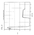
- FIGS. 1-4 illustrate refractive index profiles of fibers made in accordance with the invention.
- FIG. 5 illustrates insertion loss as a function of wavelength for a C and L-band fiber made in accordance with the invention.
- FIG. 6 illustrates residual dispersion per unit length as a function of wavelength when a C and L band dispersion compensating fiber made in accordance with the invention are used in combination with Corning LEAF® optical fiber.
- FIG. 7 illustrates a refractive index profile of a fiber made in accordance with the present invention.
- FIG. 1 An exemplary embodiment of a refractive index profile of a fiber in accordance with the present invention is shown in FIG. 1 .
- Refractive index profile 10 consists of a central up-doped region 12 having peak ⁇ 1 which is surrounded by a first down-doped moat region 14 having peak negative A2, which is in turn surrounded by annular ring and a second up-doped region 16 having peak ⁇ 3, all of which are surrounded by cladding region 18 .
- regions 12 and 16 are formed using germania doped SiO 2 , although other forms of index refraction increasing dopants could also be employed to achieve the fibers disclosed herein, so long as the same general refractive index profile is achieved.
- region 14 is preferably formed using fluorine doped SiO 2
- other index of refraction decreasing dopants could be employed besides fluorine.
- Cladding region 18 is preferably formed of silica.
- cladding region 13 could also include index of refraction increasing or decreasing in dopants, so long as the ⁇ versus radius relationship illustrated is maintained.
- ⁇ 1 ranges between 1.0 and 2.5 percent and comprises an outer radius r 1 (in FIG. 1, r 1 is drawn to the point where the profile intersects the x-axis) between about 1 to 3 microns, ⁇ 2 is less than about ⁇ 0.3 percent, more preferably less than ⁇ 0.4 percent, and has an outer radius r 2 which ranges between about 3.5 and 8 microns, and ⁇ 3 is between about 0.2 to 1.2 percent and comprises a center radius r 3 (drawn to the center of the segment) between about 5 to 12 microns outer radius, as used herein, means the distance measured from the centerline of the optical fiber to the outer region of the segment, i.e., where the outer region of the index segment intersects the x-axis (which is also equal to the index of the cladding material 18 ). Center radius, on the other hand, is measured to the center of the core segment.
- ⁇ 1 of segment 12 is between 1.2 and 2.2 percent and comprises an outer radius r 1 between about 1 to 2 microns
- ⁇ 2 of segment 14 is between than about ⁇ 0.5 and ⁇ 1.0 percent
- the third annular segment 16 can vary more in A versus radial dimension than segments 12 and 14 .
- higher and narrower annular rings segment 16 may be replaced by shorter and wider annular ring segment 16 to achieve fiber exhibiting the desired properties in accordance with the invention.
- the third annular segment 16 may be selected from the group consisting of a) a ⁇ 3 between about 0.5 to 1.0 percent and a center radius of 5 to 12 microns, and a half-height width between about 0.5 to 2.5 microns, and b) a ⁇ 3 between about 0.1 to 0.5 percent, a center radius of 6 to 12 microns, and a half-height width between about 1.5 to 3 microns.
- ⁇ 1 of segment 12 is between 1.0 and 2.5 percent and comprises an outer radius between about 1 to 3 microns
- ⁇ 2 of segment 14 is less than about ⁇ 0.5 percent
- ⁇ 3 of segment 16 is between about 0.2 to 1.0 percent and comprises a center radius r 3 between about 5 to 12 microns.
- Fibers made in accordance with the invention may also exhibit a fiber cut off wavelength which is higher than the C or L band (i.e. higher than 1650 nm). Consequently, when clad with silica cladding, the fibers disclosed herein are few moded, rather than single mode, at 1550 nm. Conversely, previous prior art dispersion compensating fibers have been designed to support only one mode in the transmission window of interest. Long haul fibers designed to be few moded with high fiber cutoff wavelengths often support only one mode in the cable as the cabling process reduces the cutoff wavelength.
- the dispersion compensating optical fibers disclosed herein are deployed in such dispersion compensating modules wherein the fiber is wound around a hub.
- the hub is cylindrical, and has a diameter of less than about 12 inches, more preferably less than about 10 inches, and most preferably less than about 6 inches, and the length of fiber deployed therein is greater than 100 meters, more preferably greater than 500 meters.
- the fiber design may be modified to increase the fiber cut off wavelength without effecting any of the other optical properties deleteriously.
- the raised index regions 12 and 16 were formed using germania doping, and the lowered index region 14 was formed using fluorine doping.
- Outer clad region 18 was pure silica, and the outer diameter of the resultant fiber was 125 microns.
- the resultant fiber exhibited a dispersion at 1550 of approximately ⁇ 107 ps/nm/km, a dispersion slope of about ⁇ 1.18 and a ⁇ value of about 90.
- the effective area of this fiber was approximately 16 square microns, and the fiber cutoff wavelength was longer than 1650, the detection limit of the equipment. In fact, for all of the fibers disclosed herein, the fiber cutoff wavelength was too high to be measured using current equipment. Additional examples of embodiments in accordance with the invention are listed in Tables 1, 2, and 3.
- Fibers described in Tables 1 and 2 fall within a particularly preferred range of refractive index profiles in accordance with the invention, in which ⁇ 1 ranges between 1.5 and 2.2 percent and comprises an outer radius r 1 (drawn to the point where the profile intersects the x-axis) between about 1 to 3 microns, ⁇ 2 is less than about ⁇ 0.4 percent, and has an outer radius r 2 which ranges between about 4.5 and 7.5 microns, and ⁇ 3 is between about 0.2 to 1.2 percent and comprises a center radius r 3 (drawn to the center of the segment) between about 5 to 12 microns outer radius, as used herein, means the distance measured from the centerline of the optical fiber to the outer region of the segment, e.g., where the outer region of the index segment intersects the x-axis (which is also equal to the index of the cladding material 18 ). Center radius, on the other hand, is measured to the center of the core segment.
- the effective area of all of the examples in Table 1 were between 15 and 17 ⁇ m 2 and attenuation was less than 1 dB/km. All of the results shown in Table 1 above are for fibers that were drawn to 125 micron diameter fiber. These resultant properties can be modified to some extent by drawing the optical fibers to larger or smaller diameters. For example, when the profile disclosed in FIG. 2 was drawn to a diameter of 120 microns, the dispersion at 1550 was ⁇ 232 ps/nm/km, the dispersion slope was ⁇ 2.52 ps/nm 2 /km, and the ⁇ value remained at about 92.
- the fiber described in Table 2 below has excellent utility as a fiber for use in the L-band to compensate for the dispersion created in optical communications systems which employ LEAF fiber.
- the properties at 1590 nm for this fiber are set forth in Table 2.
- the Example 7 fiber exhibits a ⁇ value of about 92, a dispersion of ⁇ 84 ps/nm/km, and a dispersion slope of ⁇ 0.9 ps/nm 2 /km.
- a first fiber e.g. Example 5
- a second fiber e.g., Example 7
- These two fibers could therefore be employed together within a single dispersion compensating module to compensate for dispersion over both the C-band (e.g., 1530-1565 nm) and L-band (e.g., 1565-1625 nm) transmission windows.
- These two fibers in combination are capable of extremely good dispersion compensation of optical communications systems which employ LEAF optical fiber.
- Such optical communications systems typically consists of, for example, at least a signal transmitter and signal receiver, and one or more dispersion compensating modules over the path of communication to compensate for dispersion which builds up in the transmitted signal.
- FIG. 5 illustrates a plot of absolute insertion losses of these two fibers made in accordance with the invention, a first fiber 30 (Example 5) having a ⁇ of 48 at 1550 and a second fiber 32 (Example 7) having a ⁇ of 92 at 1590 nm.
- the lower ⁇ of the Example 5 fiber is very well suited for dispersion and dispersion slope compensation of Corning's LEAF optical fiber in the C-band, with relative flat insertion loss across the C-band.
- the higher ⁇ of the Example 7 fiber is well suited for dispersion and dispersion slope compensation of LEAF in the L band.
- the bend edge of the fiber does not start until 1615 nm.
- edge channels in Ultra-broad band (>40 nm bandwidth) and long haul systems (up to 600 km) or Ultra long haul (>1000 km) and broadband (32 nm) systems are expected to be dispersion limited.
- edge channels in Ultra-broad band (>40 nm bandwidth) and long haul systems (up to 600 km) or Ultra long haul (>1000 km) and broadband (32 nm) systems are expected to be dispersion limited.
- edge channels in Ultra-broad band (>40 nm bandwidth) and long haul systems (up to 600 km) or Ultra long haul (>1000 km) and broadband (32 nm) systems are expected to be dispersion limited.
- a re-circulating loop (125 km loop) test conducted with 32 channels in the C-band it was found that ever after 6 round trips all of the channels had a Q that was greater than
- FIG. 4 illustrates an alternative embodiment of the invention having a relatively wider annular segment 16 compared to the other embodiments.
- Examples 8, 9, and 10 have profiles similar to those in FIG. 4 and having the parameters as set forth in Table 3.
- Fibers described in Table 3 fall within a particularly preferred range of refractive index profiles in accordance with the invention, in which ⁇ 1 ranges between 1.0 and 2.0 percent and comprises an outer radius r 1 (drawn to the point where the profile intersects the x-axis) between about 1 to 3 microns, ⁇ 2 is less than about ⁇ 0.3 percent, and has an outer radius r 2 which ranges between about 4.0 and 7.0 microns, and ⁇ 3 is between about 0.2 to 0.8 percent and comprises a center radius r 3 (drawn to the center of the segment) between about 7 to 12 microns, and a ⁇ 3 half height peak width of about 5 to 10 microns.
- the profiles are particular good for obtaining low kappas at 1550 nm, e.g. between about 45 and
- FIG. 7 illustrates another embodiment of the slope compensating optical fiber in accordance with the present invention. This embodiment best illustrates the spacing of the up-doped ring region 116 away from the outer diameter r2 of the down-doped moat region 114 .
- the fiber profile 110 shown in FIG. 7 provides a dispersion at 1550 nm which is between about ⁇ 30 and ⁇ 200 ps/nm/km; a dispersion slope less than ⁇ 1.1 ps/nm 2 /km; and a kappa value between 40 and 95. This provides a fiber that may compensate for both slope and dispersion by exhibiting a relatively large negative slope and relatively large negative dispersion.
- the dispersion slope compensating optical fiber in accordance with the invention includes a dispersion at 1550 nm which is between ⁇ 90 and ⁇ 150 ps/nm/km; a dispersion slope less than ⁇ 1.5 ps/nm 2 /km; and a kappa value between 40 and 95.
- the above-mentioned dispersion slope compensating optical fiber preferably includes a refractive index profile 110 as shown in FIG.
- the preferred embodiment of the profile 110 has a ⁇ 1 between about 1.6 percent to 2.0 percent.
- the outer radius r 1 of the central core region 112 is located at between about 1.5 to 2.0 microns.
- the annular moat region 114 surrounding and in contact with the central region 112 has a ⁇ 2 which is preferably less than about ⁇ 0.6 percent and has an outer radius r 2 between about 4.5 and 6 microns.
- the spaced ring region 116 includes ⁇ 3 is between about 0.4 to 0.8 percent and comprises a center radius r 3 between about 6 to 10 microns.
- the peak of the region 116 is located such that r3 is spaced from r2 by greater than 1.0 microns, and more preferably greater than 2 microns.
- a dispersion compensating optical fiber in accordance with the invention that is particularly effective at compensating for dispersion or dispersion slope in the C and L bands has a refractive index profile, as shown in FIG. 7, which is selected to result in a dispersion slope in said fiber which is less than ⁇ 1.5 ps/nm 2 /km over the wavelength range 1525 to 1565 nm; a dispersion at 1550 nm which is less than ⁇ 75 ps/nm/km; and a kappa value, obtained by dividing the dispersion by the dispersion slope, that is between 40 and 90.
- the refractive index profile of said fiber comprises a central segment having a ⁇ 1, a second annular segment which surrounds said central segment having ⁇ 2, a third annular segment which surrounds said second segment having ⁇ 3 and a cladding layer comprising ⁇ c, wherein ⁇ 1> ⁇ 3> ⁇ c> ⁇ 2.
- a dispersion compensating fiber includes a refractive index profile selected to result in a dispersion slope in said fiber which is less than ⁇ 0.8 ps/nm 2 /km over the wavelength range 1525 to 1565 nm; a dispersion at 1550 nm which is less than ⁇ 100 ps/nm/km; and a kappa value obtained by dividing the dispersion by the dispersion slope, that is between 40 and 90.
- the refractive index profile of this embodiment of fiber comprises a central segment having a ⁇ 1 and an outer radius r1, a second annular segment which surrounds the central segment having a ⁇ 2 and an outer radius r2, a third annular segment which surrounds the second segment having a ⁇ 3 and a cladding layer comprising ⁇ c, wherein ⁇ 1> ⁇ 3> ⁇ c> ⁇ 2, and wherein the core moat ratio r1/r2 is less than 0.4.
Landscapes
- Physics & Mathematics (AREA)
- Chemical & Material Sciences (AREA)
- Dispersion Chemistry (AREA)
- General Physics & Mathematics (AREA)
- Optics & Photonics (AREA)
- Optical Communication System (AREA)
Priority Applications (3)
| Application Number | Priority Date | Filing Date | Title |
|---|---|---|---|
| US09/802,696 US6445864B2 (en) | 2000-03-24 | 2001-03-09 | Dispersion compensating optical fiber |
| US10/122,250 US6546178B2 (en) | 2000-03-24 | 2002-04-11 | Dispersion compensating optical fiber |
| US10/366,915 US6731848B2 (en) | 2000-03-24 | 2003-02-14 | Dispersion compensating optical fiber |
Applications Claiming Priority (3)
| Application Number | Priority Date | Filing Date | Title |
|---|---|---|---|
| US19205600P | 2000-03-24 | 2000-03-24 | |
| US19643700P | 2000-04-12 | 2000-04-12 | |
| US09/802,696 US6445864B2 (en) | 2000-03-24 | 2001-03-09 | Dispersion compensating optical fiber |
Related Child Applications (2)
| Application Number | Title | Priority Date | Filing Date |
|---|---|---|---|
| US10/122,250 Continuation US6546178B2 (en) | 2000-03-24 | 2002-04-11 | Dispersion compensating optical fiber |
| US10/366,915 Continuation US6731848B2 (en) | 2000-03-24 | 2003-02-14 | Dispersion compensating optical fiber |
Publications (2)
| Publication Number | Publication Date |
|---|---|
| US20020012510A1 US20020012510A1 (en) | 2002-01-31 |
| US6445864B2 true US6445864B2 (en) | 2002-09-03 |
Family
ID=26887682
Family Applications (3)
| Application Number | Title | Priority Date | Filing Date |
|---|---|---|---|
| US09/802,696 Expired - Fee Related US6445864B2 (en) | 2000-03-24 | 2001-03-09 | Dispersion compensating optical fiber |
| US10/122,250 Expired - Lifetime US6546178B2 (en) | 2000-03-24 | 2002-04-11 | Dispersion compensating optical fiber |
| US10/366,915 Expired - Fee Related US6731848B2 (en) | 2000-03-24 | 2003-02-14 | Dispersion compensating optical fiber |
Family Applications After (2)
| Application Number | Title | Priority Date | Filing Date |
|---|---|---|---|
| US10/122,250 Expired - Lifetime US6546178B2 (en) | 2000-03-24 | 2002-04-11 | Dispersion compensating optical fiber |
| US10/366,915 Expired - Fee Related US6731848B2 (en) | 2000-03-24 | 2003-02-14 | Dispersion compensating optical fiber |
Country Status (7)
| Country | Link |
|---|---|
| US (3) | US6445864B2 (de) |
| EP (1) | EP1266252A2 (de) |
| JP (1) | JP2003528344A (de) |
| KR (1) | KR100818400B1 (de) |
| CN (1) | CN1520527B (de) |
| AU (1) | AU2001266555A1 (de) |
| WO (1) | WO2001071391A2 (de) |
Cited By (40)
| Publication number | Priority date | Publication date | Assignee | Title |
|---|---|---|---|---|
| US20020154877A1 (en) * | 2001-02-26 | 2002-10-24 | Ming-Jun Li | Waveguide fiber for dispersion and slope compensation |
| US6498874B1 (en) * | 1997-12-22 | 2002-12-24 | Sumitomo Electric Industries, Ltd. | Optical transmission line |
| US6574405B2 (en) * | 2000-09-01 | 2003-06-03 | The Furukawa Electric Co., Ltd. | Optical fiber and optical transmission line using this optical fiber |
| US20030103747A1 (en) * | 2001-11-30 | 2003-06-05 | Jeong-Sik Cho | Wide band dispersion-controlled fiber |
| US20030133678A1 (en) * | 2001-12-05 | 2003-07-17 | Kazunori Mukasa | Optical fiber, optical fiber module and optical amplifier |
| US6597848B1 (en) | 1999-04-30 | 2003-07-22 | Corning Incorporated | Dispersion compensating fiber |
| US6625362B2 (en) * | 2000-07-14 | 2003-09-23 | Fujitsu Limited | Dispersion compensating optical fiber |
| US6650814B2 (en) | 2001-12-11 | 2003-11-18 | Corning Incorporated | Single mode dispersion compensating optical fiber |
| US6654531B2 (en) * | 2001-02-21 | 2003-11-25 | Fitel Usa Corp. | Dispersion-compensating module |
| US6665481B2 (en) * | 2001-12-20 | 2003-12-16 | Corning Incorporated | Low MPI dispersion compensating fiber |
| US6668121B2 (en) * | 2000-09-21 | 2003-12-23 | The Furukawa Electric Co., Ltd. | Optical fiber, and dispersion compensator using same, optical transmission line using same and optical transmission system using same |
| US20040033015A1 (en) * | 2002-08-19 | 2004-02-19 | Andersen Michael Norgaard | Dispersion compensation module comprising a single spool on which multiple optical fibers are wound |
| US6731848B2 (en) | 2000-03-24 | 2004-05-04 | Corning Incorporated | Dispersion compensating optical fiber |
| US6782172B2 (en) * | 2000-06-23 | 2004-08-24 | Sumitomo Electric Industries, Ltd. | Optical fiber, optical transmission line and dispersion compensating module |
| US20040179849A1 (en) * | 2003-03-14 | 2004-09-16 | Tetsuya Miyazaki | Optical receiver and method for controlling dispersion compensation |
| US20040190847A1 (en) * | 2003-03-27 | 2004-09-30 | Bickham Scott R. | High dispersion, wide band dispersion compensating optical fiber |
| US20050013571A1 (en) * | 2003-07-18 | 2005-01-20 | Wood William A. | Large effective area, low kappa, dispersion compensating optical fiber and telecommunication span including same |
| US20050036752A1 (en) * | 2003-08-13 | 2005-02-17 | Burke James P. | Dispersion compensated optical fiber transmission system and module including micro-structured optical fiber |
| US20050058418A1 (en) * | 2003-01-23 | 2005-03-17 | Sterlite Optical Technologies Limited | Dispersion optimized fiber having higher spot area |
| US20050175303A1 (en) * | 2004-02-07 | 2005-08-11 | Yun-Geun Jang | Optical fiber for metro network |
| US20050185905A1 (en) * | 2004-02-20 | 2005-08-25 | Burke James P. | Dispersion correction fiber, transmission system and method of operating same |
| US20050201700A1 (en) * | 2004-03-09 | 2005-09-15 | Fujikura Ltd. | Dispersion compensating fiber module, and optical fiber transmission line |
| US20050265676A1 (en) * | 2004-05-28 | 2005-12-01 | Ju-Chang Han | Optical fiber for metro network |
| US20060062534A1 (en) * | 2001-06-26 | 2006-03-23 | Kazuhiko Aikawa | Dispersion compensating optical fiber and dispersion compensating optical fiber module |
| US20060126160A1 (en) * | 2004-12-14 | 2006-06-15 | Lee Won K | Dispersion compensating fiber for S-band discrete Raman amplifier |
| US20070237477A1 (en) * | 2006-04-05 | 2007-10-11 | Wood William A | Highly dispersive dispersion compensating fiber for transmission fiber and transmission system utilizing same |
| US20080219667A1 (en) * | 2006-10-16 | 2008-09-11 | The Furukawa Electric Co, Ltd. | Optical communication system and dispersion-compensating optical fiber |
| EP3733103A1 (de) | 2019-04-30 | 2020-11-04 | Biosense Webster (Israel) Ltd. | Abbildungsgitter mit einer elektrodenanordnung hoher dichte |
| EP3915477A1 (de) | 2020-05-29 | 2021-12-01 | Biosense Webster (Israel) Ltd | Elektrodenvorrichtung zur diagnose von arrhythmien |
| US11218226B2 (en) * | 2017-03-01 | 2022-01-04 | Corning Incorporated | Quantum communication systems having dispersion compensating optical fiber links |
| US11431419B2 (en) | 2018-11-27 | 2022-08-30 | Corning Incorporated | Quantum key distribution systems having low loss dispersion limiting fibers |
| WO2023007324A1 (en) | 2021-07-30 | 2023-02-02 | Biosense Webster (Israel) Ltd. | Planar end effector with irrigation |
| EP4190257A2 (de) | 2021-11-16 | 2023-06-07 | Biosense Webster (Israel) Ltd | Planarer katheter mit überlappenden elektrodenpaaren |
| EP4205684A1 (de) | 2021-12-31 | 2023-07-05 | Biosense Webster (Israel) Ltd | Rekonfigurierbare elektrodenvorrichtung zur diagnose von arrhythmien |
| EP4285850A1 (de) | 2022-05-31 | 2023-12-06 | Biosense Webster (Israel) Ltd. | Endeffektor für einen katheter, umfassend ein mapping-gitter mit hochdichter elektrodenanordnung und reduktion mechanischer spannung |
| EP4309606A1 (de) | 2022-07-22 | 2024-01-24 | Biosense Webster (Israel) Ltd. | Schleifenkonfiguration für herzkatheterendeffektor |
| EP4368133A1 (de) | 2022-11-11 | 2024-05-15 | Biosense Webster (Israel) Ltd. | Elektrodenkatheter mit gewellter stützstruktur |
| US12232874B2 (en) | 2020-05-29 | 2025-02-25 | Biosense Webster (Israel) Ltd. | Electrode apparatus for diagnosis of arrhythmias |
| US12466166B2 (en) | 2018-11-29 | 2025-11-11 | Corning Incorporated | Light weight hurricane window and laminate with untempered sheet |
| US12708436B2 (en) | 2023-11-14 | 2026-08-18 | Biosense Webster (Israel) Ltd. | Multi-electrode catheter with interlaced substrate |
Families Citing this family (25)
| Publication number | Priority date | Publication date | Assignee | Title |
|---|---|---|---|---|
| CA2344389A1 (en) | 1998-09-18 | 2000-03-30 | Sumitomo Electric Industries, Ltd. | Dispersion compensating fiber |
| JP5033290B2 (ja) * | 2000-03-30 | 2012-09-26 | コーニング インコーポレイテッド | 分散勾配補償光導波路ファイバ |
| US6477306B2 (en) | 2000-04-11 | 2002-11-05 | Sumitomo Electric Industries, Ltd. | Dispersion-compensating optical fiber, and, optical transmission line and dispersion-compensating module respectively including the same |
| JP2001296444A (ja) * | 2000-04-11 | 2001-10-26 | Sumitomo Electric Ind Ltd | 分散補償光ファイバ、光伝送路および分散補償モジュール |
| CA2405348A1 (en) * | 2000-04-13 | 2001-11-01 | Ocean Spray Cranberries, Inc. | Novel compositions derived from cranberry and grapefruit and therapeutic uses therefor |
| AU2002251846A1 (en) * | 2001-03-30 | 2002-10-15 | Corning Incorporated | Optical transmission line |
| US20030059186A1 (en) * | 2001-09-26 | 2003-03-27 | Hebgen Peter G. | L-band dispersion compensating fiber and transmission system including same |
| WO2003032040A1 (en) * | 2001-10-10 | 2003-04-17 | Corning Incorporated | Dispersion slope compensating optical fiber |
| US6937805B2 (en) | 2001-10-26 | 2005-08-30 | Fujikura, Ltd. | Dispersion compensating fiber and dispersion compensating fiber module |
| US6711332B2 (en) * | 2001-11-05 | 2004-03-23 | Corning Incorporated | Highly negative-slope dispersion compensating fiber and transmission system including same |
| US6751390B2 (en) * | 2001-12-11 | 2004-06-15 | Corning Incorporation | Dispersion and dispersion slope compensating fiber and optical transmission system utilizing same |
| US6757468B2 (en) * | 2002-03-14 | 2004-06-29 | Corning Incorporated | Dispersion compensation optical fiber and optical transmission line using same |
| FR2838261B1 (fr) * | 2002-04-05 | 2004-07-09 | Cit Alcatel | Fibre de compensation de dispersion utilisant un mode d'ordre superieur |
| US6931186B2 (en) | 2002-04-05 | 2005-08-16 | Alcatel | Chromatic dispersion compensation module |
| US6975801B2 (en) | 2002-07-15 | 2005-12-13 | Corning Incorporated | Dispersion compensating fiber for low slope transmission fiber and optical transmission line utilizing same |
| JP2004061741A (ja) * | 2002-07-26 | 2004-02-26 | Sumitomo Electric Ind Ltd | 光ファイバ、光伝送路および光通信システム |
| US20040022509A1 (en) * | 2002-07-31 | 2004-02-05 | Pushkar Tandon | Non-zero dispersion shifted optical fiber with depressed core having large effective area, low slope and low dispersion |
| US7102812B2 (en) * | 2002-10-15 | 2006-09-05 | Corning Incorporated | Devices and methods for raman amplification and dispersion compensation |
| US6959564B2 (en) * | 2003-03-31 | 2005-11-01 | Sara Lee Corporation | Panty construction with moisture management liner |
| US6925237B2 (en) * | 2003-09-24 | 2005-08-02 | Corning Incorporated | High figure of merit dispersion compensating fiber for standard single mode fiber and transmission system utilizing same |
| US6985662B2 (en) | 2003-10-30 | 2006-01-10 | Corning Incorporated | Dispersion compensating fiber for moderate dispersion NZDSF and transmission system utilizing same |
| FR2871899B1 (fr) * | 2004-06-22 | 2006-09-15 | Alcatel Sa | Fibre optique a compensation de dispersion chromatique |
| FR2887037B1 (fr) | 2005-06-14 | 2007-08-24 | Draka Comteq France | Fibre de compensation de la dispersion chromatique et de la pente de dispersion chromatique |
| US20110166562A1 (en) * | 2010-01-04 | 2011-07-07 | Ceramoptec Industries, Inc. | High Durability Side Fire Optical Fiber for High Power Applications |
| WO2013090759A1 (en) | 2011-12-14 | 2013-06-20 | Ofs Fitel, Llc | Bend compensated filter fiber |
Citations (20)
| Publication number | Priority date | Publication date | Assignee | Title |
|---|---|---|---|---|
| GB598554A (en) | 1943-11-19 | 1948-02-20 | Farnsworth Television & Radio | Focus control for cathode ray tubes |
| FR1076250A (fr) | 1953-02-24 | 1954-10-25 | Deka Soc | Sécheuse-glaceuse rotative pour épreuves photographiques |
| US4715679A (en) | 1981-12-07 | 1987-12-29 | Corning Glass Works | Low dispersion, low-loss single-mode optical waveguide |
| US5361319A (en) | 1992-02-04 | 1994-11-01 | Corning Incorporated | Dispersion compensating devices and systems |
| US5448674A (en) | 1992-11-18 | 1995-09-05 | At&T Corp. | Article comprising a dispersion-compensating optical waveguide |
| US5553185A (en) | 1994-12-27 | 1996-09-03 | Corning Incorporated | Controlled dispersion optical waveguide |
| US5555340A (en) | 1994-03-23 | 1996-09-10 | Sumitomo Electric Industries, Ltd. | Optical transmission system with dispersion compensating optical fiber |
| US5568583A (en) | 1994-09-13 | 1996-10-22 | Furukawa Electric Co., Ltd. | Dispersion compensating optical fiber for wavelength multiplex transmission and method using same |
| US5581647A (en) | 1994-08-26 | 1996-12-03 | Sumitomo Electric Industries, Ltd. | Method of fabricating dispersion compensation fiber |
| US5673354A (en) | 1995-03-10 | 1997-09-30 | The Furukawa Electric Co. Ltd. | Dispersion compensating optical fiber |
| US5740297A (en) | 1995-08-31 | 1998-04-14 | Sumitomo Electric Industries, Ltd. | Dispersion-compensating fiber and method of fabricating the same |
| US5838867A (en) | 1996-04-15 | 1998-11-17 | Sumitomo Electric Industries, Ltd. | Dispersion compensating fiber and optical transmission system including the same |
| JPH10319266A (ja) | 1997-05-20 | 1998-12-04 | Fujikura Ltd | 分散補償光ファイバ |
| US5999679A (en) | 1997-07-14 | 1999-12-07 | Corning Incorporated | Dispersion compensating single mode waveguide |
| US6009221A (en) * | 1997-09-10 | 1999-12-28 | The Furukawa Electric Co., Ltd. | Dispersion slope compensating optical fiber |
| US6031955A (en) * | 1997-03-11 | 2000-02-29 | The Furukawa Electric Co., Ltd. | Dispersion compensating optical fiber |
| WO2000017684A1 (fr) | 1998-09-18 | 2000-03-30 | Sumitomo Electric Industries, Ltd. | Fibre a compensation de dispersion |
| WO2000067053A1 (en) | 1999-04-30 | 2000-11-09 | Corning Incorporated | Dispersion compensating fiber |
| WO2000070378A1 (en) | 1999-05-17 | 2000-11-23 | The Furukawa Electric Co., Ltd. | Optical fiber and optical transmission line comprising the optical fiber |
| WO2001001177A1 (fr) | 1999-06-29 | 2001-01-04 | Alcatel | Fibre optique a compensation de dispersion chromatique |
Family Cites Families (11)
| Publication number | Priority date | Publication date | Assignee | Title |
|---|---|---|---|---|
| US3215741A (en) | 1963-01-08 | 1965-11-02 | Du Pont | Process for preparing maine oxides |
| EP0857313A4 (de) * | 1996-07-31 | 2000-04-12 | Corning Inc | Dispersionskompensierter monomodiger wellenleiter |
| US6421490B1 (en) * | 1998-02-23 | 2002-07-16 | Corning Incorporated | Low slope dispersion managed waveguide |
| EP0989420A1 (de) * | 1998-03-16 | 2000-03-29 | The Furukawa Electric Co., Ltd. | Optischer wellenlängenmultiplexübertragungkanal und hierfür verwendete optische faser |
| CA2344389A1 (en) | 1998-09-18 | 2000-03-30 | Sumitomo Electric Industries, Ltd. | Dispersion compensating fiber |
| CA2392328A1 (en) * | 1999-11-22 | 2001-05-31 | Corning Incorporated | Dispersion shifted large effective area waveguide fiber |
| US6453102B1 (en) * | 2000-02-07 | 2002-09-17 | Corning Incorporated | Dispersion compensating module and mode converter, coupler and dispersion compensating optical waveguide therein |
| JP2001311849A (ja) * | 2000-02-25 | 2001-11-09 | Furukawa Electric Co Ltd:The | 低分散光ファイバおよびその低分散光ファイバを用いた光伝送システム |
| US6445864B2 (en) | 2000-03-24 | 2002-09-03 | Corning Incorporated | Dispersion compensating optical fiber |
| JP5033290B2 (ja) * | 2000-03-30 | 2012-09-26 | コーニング インコーポレイテッド | 分散勾配補償光導波路ファイバ |
| FR2815418B1 (fr) | 2000-10-16 | 2003-05-16 | Cit Alcatel | Fibre pour la compensation de dispersion chromatique d'une fibre nz-dsf a dispersion chromatique positive |
-
2001
- 2001-03-09 US US09/802,696 patent/US6445864B2/en not_active Expired - Fee Related
- 2001-03-14 KR KR1020027012634A patent/KR100818400B1/ko not_active Expired - Fee Related
- 2001-03-14 WO PCT/US2001/008190 patent/WO2001071391A2/en not_active Ceased
- 2001-03-14 EP EP01944112A patent/EP1266252A2/de not_active Withdrawn
- 2001-03-14 JP JP2001569525A patent/JP2003528344A/ja not_active Ceased
- 2001-03-14 AU AU2001266555A patent/AU2001266555A1/en not_active Abandoned
- 2001-03-14 CN CN01810141.0A patent/CN1520527B/zh not_active Expired - Fee Related
-
2002
- 2002-04-11 US US10/122,250 patent/US6546178B2/en not_active Expired - Lifetime
-
2003
- 2003-02-14 US US10/366,915 patent/US6731848B2/en not_active Expired - Fee Related
Patent Citations (21)
| Publication number | Priority date | Publication date | Assignee | Title |
|---|---|---|---|---|
| GB598554A (en) | 1943-11-19 | 1948-02-20 | Farnsworth Television & Radio | Focus control for cathode ray tubes |
| FR1076250A (fr) | 1953-02-24 | 1954-10-25 | Deka Soc | Sécheuse-glaceuse rotative pour épreuves photographiques |
| US4715679A (en) | 1981-12-07 | 1987-12-29 | Corning Glass Works | Low dispersion, low-loss single-mode optical waveguide |
| US5361319A (en) | 1992-02-04 | 1994-11-01 | Corning Incorporated | Dispersion compensating devices and systems |
| US5448674A (en) | 1992-11-18 | 1995-09-05 | At&T Corp. | Article comprising a dispersion-compensating optical waveguide |
| US5555340A (en) | 1994-03-23 | 1996-09-10 | Sumitomo Electric Industries, Ltd. | Optical transmission system with dispersion compensating optical fiber |
| US5581647A (en) | 1994-08-26 | 1996-12-03 | Sumitomo Electric Industries, Ltd. | Method of fabricating dispersion compensation fiber |
| US5568583A (en) | 1994-09-13 | 1996-10-22 | Furukawa Electric Co., Ltd. | Dispersion compensating optical fiber for wavelength multiplex transmission and method using same |
| US5553185A (en) | 1994-12-27 | 1996-09-03 | Corning Incorporated | Controlled dispersion optical waveguide |
| US5673354A (en) | 1995-03-10 | 1997-09-30 | The Furukawa Electric Co. Ltd. | Dispersion compensating optical fiber |
| US5740297A (en) | 1995-08-31 | 1998-04-14 | Sumitomo Electric Industries, Ltd. | Dispersion-compensating fiber and method of fabricating the same |
| US5838867A (en) | 1996-04-15 | 1998-11-17 | Sumitomo Electric Industries, Ltd. | Dispersion compensating fiber and optical transmission system including the same |
| US6349163B1 (en) * | 1996-07-31 | 2002-02-19 | Corning Incorporated | Dispersion compensating single mode waveguide |
| US6031955A (en) * | 1997-03-11 | 2000-02-29 | The Furukawa Electric Co., Ltd. | Dispersion compensating optical fiber |
| JPH10319266A (ja) | 1997-05-20 | 1998-12-04 | Fujikura Ltd | 分散補償光ファイバ |
| US5999679A (en) | 1997-07-14 | 1999-12-07 | Corning Incorporated | Dispersion compensating single mode waveguide |
| US6009221A (en) * | 1997-09-10 | 1999-12-28 | The Furukawa Electric Co., Ltd. | Dispersion slope compensating optical fiber |
| WO2000017684A1 (fr) | 1998-09-18 | 2000-03-30 | Sumitomo Electric Industries, Ltd. | Fibre a compensation de dispersion |
| WO2000067053A1 (en) | 1999-04-30 | 2000-11-09 | Corning Incorporated | Dispersion compensating fiber |
| WO2000070378A1 (en) | 1999-05-17 | 2000-11-23 | The Furukawa Electric Co., Ltd. | Optical fiber and optical transmission line comprising the optical fiber |
| WO2001001177A1 (fr) | 1999-06-29 | 2001-01-04 | Alcatel | Fibre optique a compensation de dispersion chromatique |
Cited By (67)
| Publication number | Priority date | Publication date | Assignee | Title |
|---|---|---|---|---|
| US6498874B1 (en) * | 1997-12-22 | 2002-12-24 | Sumitomo Electric Industries, Ltd. | Optical transmission line |
| US6597848B1 (en) | 1999-04-30 | 2003-07-22 | Corning Incorporated | Dispersion compensating fiber |
| US6731848B2 (en) | 2000-03-24 | 2004-05-04 | Corning Incorporated | Dispersion compensating optical fiber |
| US6782172B2 (en) * | 2000-06-23 | 2004-08-24 | Sumitomo Electric Industries, Ltd. | Optical fiber, optical transmission line and dispersion compensating module |
| US6625362B2 (en) * | 2000-07-14 | 2003-09-23 | Fujitsu Limited | Dispersion compensating optical fiber |
| US6574405B2 (en) * | 2000-09-01 | 2003-06-03 | The Furukawa Electric Co., Ltd. | Optical fiber and optical transmission line using this optical fiber |
| US6668121B2 (en) * | 2000-09-21 | 2003-12-23 | The Furukawa Electric Co., Ltd. | Optical fiber, and dispersion compensator using same, optical transmission line using same and optical transmission system using same |
| US6654531B2 (en) * | 2001-02-21 | 2003-11-25 | Fitel Usa Corp. | Dispersion-compensating module |
| US6873776B2 (en) | 2001-02-26 | 2005-03-29 | Corning Incorporated | Waveguide fiber for dispersion and slope compensation |
| US20020154877A1 (en) * | 2001-02-26 | 2002-10-24 | Ming-Jun Li | Waveguide fiber for dispersion and slope compensation |
| US7496261B2 (en) | 2001-06-26 | 2009-02-24 | Fujikura Ltd. | Dispersion compensating optical fiber and dispersion compensating optical fiber module |
| US20060062534A1 (en) * | 2001-06-26 | 2006-03-23 | Kazuhiko Aikawa | Dispersion compensating optical fiber and dispersion compensating optical fiber module |
| US20030103747A1 (en) * | 2001-11-30 | 2003-06-05 | Jeong-Sik Cho | Wide band dispersion-controlled fiber |
| US6954573B2 (en) * | 2001-11-30 | 2005-10-11 | Samsung Electronics Co., Ltd. | Wide band dispersion-controlled fiber |
| US7085462B2 (en) * | 2001-12-05 | 2006-08-01 | The Furukawa Electric Co., Ltd. | Optical fiber, optical fiber module and optical amplifier |
| US20030133678A1 (en) * | 2001-12-05 | 2003-07-17 | Kazunori Mukasa | Optical fiber, optical fiber module and optical amplifier |
| US6650814B2 (en) | 2001-12-11 | 2003-11-18 | Corning Incorporated | Single mode dispersion compensating optical fiber |
| US6665481B2 (en) * | 2001-12-20 | 2003-12-16 | Corning Incorporated | Low MPI dispersion compensating fiber |
| US20040033015A1 (en) * | 2002-08-19 | 2004-02-19 | Andersen Michael Norgaard | Dispersion compensation module comprising a single spool on which multiple optical fibers are wound |
| US7209620B2 (en) * | 2003-01-23 | 2007-04-24 | Sterlite Optical Technologies Limited | Dispersion optimized fiber having higher spot area |
| US20050058418A1 (en) * | 2003-01-23 | 2005-03-17 | Sterlite Optical Technologies Limited | Dispersion optimized fiber having higher spot area |
| US20040179849A1 (en) * | 2003-03-14 | 2004-09-16 | Tetsuya Miyazaki | Optical receiver and method for controlling dispersion compensation |
| US7308211B2 (en) | 2003-03-14 | 2007-12-11 | Communications Research Laboratory, Independent Administrative Institution | Optical receiver and method for controlling dispersion compensation |
| US20040190847A1 (en) * | 2003-03-27 | 2004-09-30 | Bickham Scott R. | High dispersion, wide band dispersion compensating optical fiber |
| US20050013571A1 (en) * | 2003-07-18 | 2005-01-20 | Wood William A. | Large effective area, low kappa, dispersion compensating optical fiber and telecommunication span including same |
| US7003203B2 (en) | 2003-07-18 | 2006-02-21 | Corning Incorporated | Large effective area, low kappa, dispersion compensating optical fiber and telecommunication span including same |
| US20050036752A1 (en) * | 2003-08-13 | 2005-02-17 | Burke James P. | Dispersion compensated optical fiber transmission system and module including micro-structured optical fiber |
| US6993228B2 (en) | 2003-08-13 | 2006-01-31 | Corning Incorporated | Dispersion compensated optical fiber transmission system and module including micro-structured optical fiber |
| US7116876B2 (en) * | 2004-02-07 | 2006-10-03 | Samsung Electronics Co., Ltd. | Optical fiber for metro network |
| US20050175303A1 (en) * | 2004-02-07 | 2005-08-11 | Yun-Geun Jang | Optical fiber for metro network |
| CN1316268C (zh) * | 2004-02-07 | 2007-05-16 | 三星电子株式会社 | 用于城域网的光纤 |
| US20050185905A1 (en) * | 2004-02-20 | 2005-08-25 | Burke James P. | Dispersion correction fiber, transmission system and method of operating same |
| US20050201700A1 (en) * | 2004-03-09 | 2005-09-15 | Fujikura Ltd. | Dispersion compensating fiber module, and optical fiber transmission line |
| US7181115B2 (en) | 2004-03-09 | 2007-02-20 | Fujikura Ltd. | Dispersion compensating fiber module, and optical fiber transmission line |
| US20050265676A1 (en) * | 2004-05-28 | 2005-12-01 | Ju-Chang Han | Optical fiber for metro network |
| US7305165B2 (en) * | 2004-05-28 | 2007-12-04 | Samsung Electronics Co., Ltd. | Optical fiber for metro network |
| US7154663B2 (en) | 2004-12-14 | 2006-12-26 | Electronics And Telecommunications Research Institute | Dispersion compensating fiber for S-band discrete Raman amplifier |
| KR100668284B1 (ko) * | 2004-12-14 | 2007-01-16 | 한국전자통신연구원 | S밴드 분리형 라만 증폭기를 위한 분산보상광섬유 |
| US20060126160A1 (en) * | 2004-12-14 | 2006-06-15 | Lee Won K | Dispersion compensating fiber for S-band discrete Raman amplifier |
| US20070237477A1 (en) * | 2006-04-05 | 2007-10-11 | Wood William A | Highly dispersive dispersion compensating fiber for transmission fiber and transmission system utilizing same |
| US7283713B1 (en) | 2006-04-05 | 2007-10-16 | Corning Incorporated | Highly dispersive dispersion compensating fiber for transmission fiber and transmission system utilizing same |
| US20080219667A1 (en) * | 2006-10-16 | 2008-09-11 | The Furukawa Electric Co, Ltd. | Optical communication system and dispersion-compensating optical fiber |
| US11218226B2 (en) * | 2017-03-01 | 2022-01-04 | Corning Incorporated | Quantum communication systems having dispersion compensating optical fiber links |
| US11431419B2 (en) | 2018-11-27 | 2022-08-30 | Corning Incorporated | Quantum key distribution systems having low loss dispersion limiting fibers |
| US12466166B2 (en) | 2018-11-29 | 2025-11-11 | Corning Incorporated | Light weight hurricane window and laminate with untempered sheet |
| US11850051B2 (en) | 2019-04-30 | 2023-12-26 | Biosense Webster (Israel) Ltd. | Mapping grid with high density electrode array |
| EP3733103A1 (de) | 2019-04-30 | 2020-11-04 | Biosense Webster (Israel) Ltd. | Abbildungsgitter mit einer elektrodenanordnung hoher dichte |
| US12251224B2 (en) | 2019-04-30 | 2025-03-18 | Biosense Webster (Israel) Ltd. | Mapping grid with high density electrode array |
| EP4122414A1 (de) | 2019-04-30 | 2023-01-25 | Biosense Webster (Israel) Ltd. | Abbildungsgitter mit einer elektrodenanordnung hoher dichte |
| EP4483828A2 (de) | 2020-05-29 | 2025-01-01 | Biosense Webster (Israel) Ltd. | Elektrodenvorrichtung zur diagnose von arrhythmien |
| EP4477171A2 (de) | 2020-05-29 | 2024-12-18 | Biosense Webster (Israel) Ltd. | Intraluminale referenzelektrode für kardiovaskuläre behandlungsvorrichtung |
| EP4755331A2 (de) | 2020-05-29 | 2026-06-10 | Biosense Webster (Israel) Ltd. | Intraluminale referenzelektrode für kardiovaskuläre behandlungsvorrichtung |
| EP4218579A1 (de) | 2020-05-29 | 2023-08-02 | Biosense Webster (Israel) Ltd. | Intraluminale referenzelektrode für kardiovaskuläre behandlungsvorrichtung |
| EP3915477A1 (de) | 2020-05-29 | 2021-12-01 | Biosense Webster (Israel) Ltd | Elektrodenvorrichtung zur diagnose von arrhythmien |
| EP4159124A1 (de) | 2020-05-29 | 2023-04-05 | Biosense Webster (Israel) Ltd | Intraluminale referenzelektrode für kardiovaskuläre behandlungsvorrichtung |
| EP3915501A1 (de) | 2020-05-29 | 2021-12-01 | Biosense Webster (Israel) Ltd | Intraluminale referenzelektrode für kardiovaskuläre behandlungsvorrichtung |
| US12232874B2 (en) | 2020-05-29 | 2025-02-25 | Biosense Webster (Israel) Ltd. | Electrode apparatus for diagnosis of arrhythmias |
| WO2023007324A1 (en) | 2021-07-30 | 2023-02-02 | Biosense Webster (Israel) Ltd. | Planar end effector with irrigation |
| EP4190257A2 (de) | 2021-11-16 | 2023-06-07 | Biosense Webster (Israel) Ltd | Planarer katheter mit überlappenden elektrodenpaaren |
| EP4606306A2 (de) | 2021-11-16 | 2025-08-27 | Biosense Webster (Israel) Ltd. | Planarer katheter mit überlappenden elektrodenpaaren |
| EP4578389A2 (de) | 2021-12-31 | 2025-07-02 | Biosense Webster (Israel) Ltd. | Rekonfigurierbare elektrodenvorrichtung zur diagnose von arrhythmien |
| EP4205684A1 (de) | 2021-12-31 | 2023-07-05 | Biosense Webster (Israel) Ltd | Rekonfigurierbare elektrodenvorrichtung zur diagnose von arrhythmien |
| EP4285850A1 (de) | 2022-05-31 | 2023-12-06 | Biosense Webster (Israel) Ltd. | Endeffektor für einen katheter, umfassend ein mapping-gitter mit hochdichter elektrodenanordnung und reduktion mechanischer spannung |
| EP4309606A1 (de) | 2022-07-22 | 2024-01-24 | Biosense Webster (Israel) Ltd. | Schleifenkonfiguration für herzkatheterendeffektor |
| US12558013B2 (en) | 2022-07-22 | 2026-02-24 | Biosense Webster (Israel) Ltd. | Loop configuration for cardiac catheter end effector |
| EP4368133A1 (de) | 2022-11-11 | 2024-05-15 | Biosense Webster (Israel) Ltd. | Elektrodenkatheter mit gewellter stützstruktur |
| US12708436B2 (en) | 2023-11-14 | 2026-08-18 | Biosense Webster (Israel) Ltd. | Multi-electrode catheter with interlaced substrate |
Also Published As
| Publication number | Publication date |
|---|---|
| WO2001071391A2 (en) | 2001-09-27 |
| WO2001071391A3 (en) | 2002-09-12 |
| AU2001266555A1 (en) | 2001-10-03 |
| US6731848B2 (en) | 2004-05-04 |
| US6546178B2 (en) | 2003-04-08 |
| KR100818400B1 (ko) | 2008-04-01 |
| US20030021563A1 (en) | 2003-01-30 |
| EP1266252A2 (de) | 2002-12-18 |
| JP2003528344A (ja) | 2003-09-24 |
| CN1520527A (zh) | 2004-08-11 |
| CN1520527B (zh) | 2011-07-06 |
| KR20030003701A (ko) | 2003-01-10 |
| US20030147612A1 (en) | 2003-08-07 |
| US20020012510A1 (en) | 2002-01-31 |
| WO2001071391A9 (en) | 2003-01-09 |
Similar Documents
| Publication | Publication Date | Title |
|---|---|---|
| US6546178B2 (en) | Dispersion compensating optical fiber | |
| US7903917B2 (en) | Low bend loss single mode optical fiber | |
| US6477306B2 (en) | Dispersion-compensating optical fiber, and, optical transmission line and dispersion-compensating module respectively including the same | |
| US6768852B2 (en) | Dispersion and slope compensating optical fiber and transmission link including same | |
| US6829423B2 (en) | Low slope dispersion managed waveguide | |
| BR9916364B1 (pt) | Sistema de comunicação metropolitano, e, método de transmissão óptica por multiplexação por divisão de comprimento de onda | |
| US20060045450A1 (en) | Broadband optical fiber | |
| US7024083B2 (en) | Non-zero dispersion shifted optical fiber | |
| US7426327B2 (en) | Low attenuation non-zero dispersion shifted optical fiber | |
| EP1396743A2 (de) | Dispersionskompensierende optische Faser | |
| US6668120B2 (en) | Fiber for compensating the chromatic dispersion of an NZ-DSF having positive chromatic dispersion | |
| US6587627B2 (en) | Dispersion-compensating fiber, and dispersion-compensating module and hybrid optical fiber link using the same | |
| US6591050B2 (en) | Fiber for compensating chromatic dispersion of a monomode fiber in band S | |
| US6888993B2 (en) | Dispersion compensating optical fiber for SMF and transmission link including same | |
| US6229946B1 (en) | Dispersion-shifted optical fiber | |
| US7003203B2 (en) | Large effective area, low kappa, dispersion compensating optical fiber and telecommunication span including same | |
| US7106934B1 (en) | Non-zero dispersion shifted optical fiber | |
| EP1259840B1 (de) | Optische faser für wdm-übertragung | |
| US20060013548A1 (en) | Low cutoff large effective area optical fiber | |
| JP2005003794A (ja) | 光ファイバ、及びそれを用いた光伝送線路 |
Legal Events
| Date | Code | Title | Description |
|---|---|---|---|
| AS | Assignment |
Owner name: CORNING INCORPORATED, NEW YORK Free format text: ASSIGNMENT OF ASSIGNORS INTEREST;ASSIGNORS:JIANG, LEI;QI, GANG;SRIKANT, V.;AND OTHERS;REEL/FRAME:012009/0705;SIGNING DATES FROM 20010627 TO 20010718 |
|
| FPAY | Fee payment |
Year of fee payment: 4 |
|
| REMI | Maintenance fee reminder mailed | ||
| LAPS | Lapse for failure to pay maintenance fees | ||
| STCH | Information on status: patent discontinuation |
Free format text: PATENT EXPIRED DUE TO NONPAYMENT OF MAINTENANCE FEES UNDER 37 CFR 1.362 |
|
| FP | Lapsed due to failure to pay maintenance fee |
Effective date: 20100903 |