US6441912B1 - Character display apparatus and character input apparatus - Google Patents
Character display apparatus and character input apparatus Download PDFInfo
- Publication number
- US6441912B1 US6441912B1 US09/253,066 US25306699A US6441912B1 US 6441912 B1 US6441912 B1 US 6441912B1 US 25306699 A US25306699 A US 25306699A US 6441912 B1 US6441912 B1 US 6441912B1
- Authority
- US
- United States
- Prior art keywords
- line
- character
- segment
- state
- display
- Prior art date
- Legal status (The legal status is an assumption and is not a legal conclusion. Google has not performed a legal analysis and makes no representation as to the accuracy of the status listed.)
- Expired - Fee Related
Links
Images


Classifications
-
- G—PHYSICS
- G02—OPTICS
- G02F—OPTICAL DEVICES OR ARRANGEMENTS FOR THE CONTROL OF LIGHT BY MODIFICATION OF THE OPTICAL PROPERTIES OF THE MEDIA OF THE ELEMENTS INVOLVED THEREIN; NON-LINEAR OPTICS; FREQUENCY-CHANGING OF LIGHT; OPTICAL LOGIC ELEMENTS; OPTICAL ANALOGUE/DIGITAL CONVERTERS
- G02F1/00—Devices or arrangements for the control of the intensity, colour, phase, polarisation or direction of light arriving from an independent light source, e.g. switching, gating or modulating; Non-linear optics
- G02F1/01—Devices or arrangements for the control of the intensity, colour, phase, polarisation or direction of light arriving from an independent light source, e.g. switching, gating or modulating; Non-linear optics for the control of the intensity, phase, polarisation or colour
- G02F1/13—Devices or arrangements for the control of the intensity, colour, phase, polarisation or direction of light arriving from an independent light source, e.g. switching, gating or modulating; Non-linear optics for the control of the intensity, phase, polarisation or colour based on liquid crystals, e.g. single liquid crystal display cells
- G02F1/133—Constructional arrangements; Operation of liquid crystal cells; Circuit arrangements
- G02F1/1333—Constructional arrangements; Manufacturing methods
- G02F1/1343—Electrodes
- G02F1/134309—Electrodes characterised by their geometrical arrangement
- G02F1/134327—Segmented, e.g. alpha numeric display
-
- B—PERFORMING OPERATIONS; TRANSPORTING
- B41—PRINTING; LINING MACHINES; TYPEWRITERS; STAMPS
- B41J—TYPEWRITERS; SELECTIVE PRINTING MECHANISMS, i.e. MECHANISMS PRINTING OTHERWISE THAN FROM A FORME; CORRECTION OF TYPOGRAPHICAL ERRORS
- B41J3/00—Typewriters or selective printing or marking mechanisms characterised by the purpose for which they are constructed
- B41J3/407—Typewriters or selective printing or marking mechanisms characterised by the purpose for which they are constructed for marking on special material
-
- G—PHYSICS
- G09—EDUCATION; CRYPTOGRAPHY; DISPLAY; ADVERTISING; SEALS
- G09G—ARRANGEMENTS OR CIRCUITS FOR CONTROL OF INDICATING DEVICES USING STATIC MEANS TO PRESENT VARIABLE INFORMATION
- G09G3/00—Control arrangements or circuits, of interest only in connection with visual indicators other than cathode-ray tubes
- G09G3/04—Control arrangements or circuits, of interest only in connection with visual indicators other than cathode-ray tubes for presentation of a single character by selection from a plurality of characters, or by composing the character by combination of individual elements, e.g. segments using a combination of such display devices for composing words, rows or the like, in a frame with fixed character positions
- G09G3/045—Selecting complete characters
Definitions
- the present invention relates to a character display apparatus and to a character input apparatus.
- the present invention is applicable to an apparatus having a display unit in which each of the number of lines and a number of characters in each line is limited to a small value, such as a tape printing apparatus and a seal making apparatus.
- inputted characters (the term “character” includes letter, symbol, pictograph, pattern, and the like throughout the specification and the appended claims) are printed on a tape in the form of a string (hereinafter a string of characters will be referred to as “character string”, an inputted character as “input character”, and inputted character string as “input character string”) , and the tape carrying such a printed character string is discharged and then cut into several portions. Each of the portions of the tape thus obtained is called “label”.
- a small-size display unit e.g., a small-size liquid crystal display
- the number of display lines is determined to a value smaller than the maximum printable line number (e.g., four lines and eight lines) within the maximum tape width and that the number of characters in each line is determined to a value around five (e.g., six).
- the number of input character string becomes larger than that of the number of lines which the display apparatus can display.
- such indication is conducted by the following manner.
- FIG. 2 shows a display surface 1 of a display unit in a tape printing apparatus in which print allowable maximum line number (the term “print allowable maximum line number” as used herein means the maximum number of lines which can be printed) is four, and the display allowable line number is one.
- the display surface 1 has a character display area 2 which is adapted to display an input character string, and line number indicators 3 - 1 to 3 - 4 disposed at the left side portion of the display surface 1 along the top-to-bottom direction.
- Each of the indicators 3 - 1 to 3 - 4 carries thereon a numeral representing a line number in the input character string, and shows an input state and/or a display state of each line constituting the character string by assuming a blinking display state, a light-on display state, or a light-off display state.
- the blinking indicator indicates that the line of the line number denoted by the numeral applied on the blinking indicator is currently displayed in the character display area 2 . If the character display area 2 is of the type that two or more lines are displayed, only an indicator carrying the numeral indicative of the line number of the line at which the cursor stays among the display lines assumes a blinking state.
- the light-on indicator indicates that the line of the line number denoted by the numeral applied on the light-on indicator exists in the input character string.
- the cursor attached display line is denoted by a blinking indicator as described above, and therefore the cursor attached display line is excluded from the object to be displayed in the lighting-on display state. This implies that, when the character display area is of the type that two or more lines are displayed, only the line (or lines) which is (or are) not attached with the cursor is (or are) indicated by a light-on indicator.
- the line indicated by the light-on indicator includes not only a substantial line but also a null line, both of which will be defined later.
- the light-off indicator indicates that the line indicated by the light-off indicator does not exist in the input character string. That is, the line indicated by the light-off indicator is neither the substantial line nor the null line.
- the character display area 2 is an area for displaying characters.
- the dot display method (which is often called as “dot representation” or “matrix method”) is employed in which a character is displayed by turning on or off each of the dot segments arranged vertically and laterally.
- each of the line number indicators 3 - 1 to 3 - 4 is adapted to display a specific fixed numeral, and is constituted by approximately one or two segments each of which is turned on or off so as to display a predetermined fixed number.
- the indicator of this type is different in constitution and function from a general numeral displaying indicator which is constituted by seven segments arranged in the shape of a numeral “ 8 ”.
- the outline character “ 1 ” displayed in the character display area 2 is a line head mark 2 M representing that the character displayed subsequent to the line head mark 2 M is the head of the display line.
- the line head mark 2 M is not displayed when the forefront character (in the case of the present embodiment, the leftmost character in the display area) of the displayed characters is not the forefront character of the display line. For example, assuming that the allowable display character number is five and the number of the input characters is seven, if the five characters displayed in the character display area are the second to sixth characters, the line head mark 2 M is not displayed because the forefront character displayed in the character display area is not the forefront character of the display line.
- the line number indicator is provided, the user can know, even when the number of lines of the input character is larger than the display allowable line number, which line is present or absent and which line is currently inputted.
- the tape printing apparatus is so constituted as to be capable of providing information which cannot be read from the displayed manner of the characters of the input character string as much as possible, the usability of the character printing apparatus is enhanced.
- the term “substantial line” as used herein refers to a line which substantially constitutes a character regardless of whether or not the line contains a character.
- the term “null line” as used herein refers to a line meeting conditions that no character is inputted and the slewing operation is conducted in a line and that the subsequent lines contains no determined character. If the tape printing apparatus can indicate whether the display line is a substantial line or a null line as a line attribute, the user can easily know, even when the display line is changed from a substantial line to a null line, whether or not the null line is successfully accepted by the tape printing apparatus.
- the displaying manners of the line number indicators are limited to three manners: blinking display state (that is, display and non-display of outline numeral appear in a repeated manner), light-on display state (that is, outline numeral is displayed), and light-off display state, so that four or more attributes or the like cannot be displayed. Due to this limitation, in the conventional printing apparatus, it is impossible to causes the line number indicators 3 - 1 to 3 - 4 to indicate the attribute indicative of whether the display line is the substantial line or a null line.
- the present invention is accomplished in view of the above-described problems.
- It is therefore an object of the present invention is to provide a character display apparatus capable of displaying characters, such as numerals, can be displayed in any one of various displaying manners.
- Another object of the present invention is to provide a character input apparatus capable of informing the user of various kinds of information as to each line of the character input string while keeping the display device neither complicated nor large-sized.
- a first aspect of the present invention provides a character display apparatus including (1) character display means having at least a character segment formed in the shape of a character, and a background segment which is provided in such a manner as to surround the character segment and constitutes a background of an outline character; and (2) display control means for performing on-off control of the character segment and the background segment.
- a second aspect of the present invention provides a character input apparatus including: (1) display means having a character display area in which a number of lines displayed in a display area is smaller than the maximum input allowable line number and the dot display method is employed, and a plurality of line number indicators each of which corresponds to each of the lines of the input allowable maximum line number and is adapted to display the line attribute of each line, such as an input state and a display state; and (2) display control means for controlling the display of the display means, wherein (3) each of the line number indicators comprises a numeral segment in the shape of a numeral indicative of a line number, and a background segment which is provided in such a manner as to surround the numeral segment and constitutes a background of an outline numeral; and (4) the display control means performs on-off control of the numeral segment and the background segment in accordance with an input state or display state of each line.
- FIG. 1 is a plan view showing a constitution of a line number indicator of the embodiment
- FIG. 2 is a plan view showing a constitution of a display surface employed in the apparatus of the embodiment and the conventional apparatus;
- FIG. 3 is a block diagram of a constitution of electrical members
- FIG. 4 is an explanatory view illustrating the displaying manner of the line number indicators
- FIG. 5 is a flowchart showing the processing conducted in the case where the key information is inputted
- FIG. 6 is an explanatory view illustrating the correspondence between the displaying manner of the line number indicator and the contents indicated by the line number indicator.
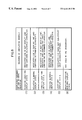
- FIG. 7 is an explanatory view showing how the display state of the line number indicator changes.
- the tape printing apparatus of the present embodiment roughly includes an input unit 10 , a control unit 20 , and an output unit 30 .
- the control unit 20 is adapted to execute processing in accordance with information supplied via input unit 10 , a processing stage at that time, and so on, and the result of the processing is outputted from the output unit 30 by way of display or print.
- the input unit 10 while not detailed, includes a key input unit 11 , which has a depressing key, a dial key and the like, and a tape width detection sensor 12 .
- the key input unit 11 is adapted to generate character code data and various types of control data to be supplied to the control unit 20 .
- the tape width detection sensor 12 is adapted to detect the width of the loaded tape and to supply tape width information to the control unit 20 . In actual, detecting the tape width by the sensor 12 is conducted by reading a physical identification element (e.g., a hole) provided on a tape cartridge and representing the width of the tape accommodated in the tape cartridge.
- a physical identification element e.g., a hole
- the output unit 30 includes members serving as a print mechanism and members serving as a display mechanism.
- the print mechanism includes a tape/ribbon feeding motor 31 and a thermal head 32 .
- the tape/ribbon feeding motor 31 is adapted to feed a tape or an ink ribbon loaded in the tape printing apparatus (both not shown) to a predetermined printing position or to the outside of the tape printing apparatus.
- the tape/ribbon feeding motor 31 is constituted by a stepping motor, a DC motor, or the like.
- the thermal head 32 is, for example, fixed, and adapted to perform printing on the running tape by the thermal transferring method.
- the tape/ribbon feeding motor 31 is driven by a motor driving circuit 33 , and the thermal head is driven by the head driving circuit 34 , both driven under the control of the control unit 20 .
- the tape on which printing is completed is cut, for example, by a cutter (not shown) which is operated by the user or driven by a motor.
- the display mechanism includes, for example, a liquid crystal display 35 which can display characters of a predetermined size arranged in a plurality of lines each having a plurality of characters.
- the number of lines is one, and the number of characters in each line is six.
- the liquid crystal display 35 is driven by a display driving circuit 36 under the control of the control unit 20 .
- the number of lines of the input character string is four or smaller as shown in FIG. 2 .
- the display surface 1 of the liquid display unit 35 has substantially the same constitution as that of the liquid crystal display unit of the above-mentioned conventional tape printing apparatus.
- the display surface 1 of the liquid crystal display 35 includes a character display area 2 , and line number indicators 3 - 1 to 3 - 4 .
- the display surface also includes attribute indicators 4 - 1 to 4 -n, which were not mentioned in the Discussion of the Related Art, each of which is adapted to indicate an attribute of the input character string.
- Each of the indicators 4 - 1 to 4 -n when it is in an on state, shows that an attribute associated with the indicator is adopted.
- the attribute of each indicator is denoted by the characters printed at a place lying in an area around the display surface 1 and beside the indicator.
- Examples of the attributes denoted by the indicators 4 - 1 to 4 -n include those on character size, those on input mode (e.g., kana input mode, romaji input mode), those on a unit of a plurality of character strings (e.g., vertical writing, and centering) , those on a unit of a character (special effect character, alphabetical style) , and those on whether or each of the other formats is adopted or not.
- input mode e.g., kana input mode, romaji input mode
- those on a unit of a plurality of character strings e.g., vertical writing, and centering
- those on a unit of a character special effect character, alphabetical style
- the number of lines of the character string displayed in the character display area 2 is one, the number of lines of the character string may be two or more.
- the liquid crystal display 35 is constituted by the character display area 2 , the line number indicator unit 3 ( 3 - 1 to 3 - 4 ), and the attribute indicator unit 4 ( 4 - 1 to 4 -n).
- the display driving circuit 36 is also constituted by a driving unit 36 a connected to the character display area 2 , a driving unit 36 b connected to the line number indicator unit 3 ( 3 - 1 to 3 - 4 ), and the driving unit 36 c connected to the attribute indicator unit 4 ( 4 - 1 to 4 -n)
- the constitution of the segments in each of the line number indicators 3 - 1 to 3 - 4 , and the driving unit 36 b connected thereto are different from conventional ones. In view of this, the constitution of the line number indicators 3 - 1 to 3 - 4 is first described.
- FIGS. 1A to 1 D shows the constitution of each of the line number indicators 3 - 1 to 3 - 4 according to this embodiment.
- the line number indicator 3 - 1 is constituted by: a numeral segment 40 - 1 , formed by one segment element, in the shape of a numeral; a background segment 41 - 1 , formed by two segment elements, which is provided in such a manner as to surround the numeral segment 40 - 1 and forms a background of an outline numeral; and a frame segment 42 - 1 , formed by four segment elements, which are provided in such a manner as to surround the background segments 41 - 1 and forms a substantially square frame surrounding the background of an outline numeral.
- the other line number indicators 3 - 2 , 3 - 3 and 3 - 4 have the same constitution as that of the line number indicator 3 - 1 , that is, are constituted by numeral segments 40 - 2 , 40 - 3 and 40 - 4 , background segments 41 - 2 , 41 - 3 and 41 - 4 , and frame segments 42 - 2 , 42 - 3 and 42 - 4 , respectively, as shown in FIGS. 1B, 1 C and 1 D.
- the line number indicators 3 - 1 to 3 - 4 of the present embodiment which have an increased number of types of segments, are different from conventional line indicators which have about one or two segments forming an outline numeral.
- the background segments 41 - 1 to 41 - 4 and the frame segments 42 - 1 to 42 - 4 are each formed by a plurality of segment elements for facilitating the wire arrangement of segment driving wires.
- the numbers of the segment element are not limited thereto. Specifically, while each of the background segments 41 - 1 to 41 - 4 is formed by two segment element in the present embodiment, the number of segment element may be one, or three or more. Also, while each of the frame segment elements 42 - 1 to 42 - 4 is formed by four segment elements in the present embodiment, the number of segment elements may be one, or two or more.
- Each of the numeral segments 40 -i and the frame segments 42 -i (i denotes any one of 1 to 4 , and i's in 40 -i and 42 -i are the same) are connected to the same segment driving line (not shown) extending from the driving unit 36 b connected to the line number indicator unit 3 . Accordingly, the numeral segment 40 -i and the frame segment 42 -i assume the same on-off state.
- the background segment 41 -i is connected to another segment driving line (not shown) extending from the driving unit 3 Gb connected to the line number indicator unit 3 .
- FIGS. 4 A 1 to 4 D 1 shows a display state of each of the line number indicators 3 - 1 to 3 - 4 in which the background segment 41 -i is controlled to an on-state while both of the numeral segment 40 -i and the frame segment 42 -i are controlled to an off-state.
- FIGS. 4 A 2 to 4 D 2 shows a display state of each of the line number indicators 3 - 1 to 3 - 4 in which the background segment 41 -i is controlled to an off-state while both of the numeral segment 40 -i and the frame segment 42 -i are controlled to an on-state.
- each of the line number indicators is brought into a state in which the indicator cannot be seen (that is, in the state in which the indicator is not displayed).
- the numeral written on the indictor is not distinctively displayed, so that this display state is not used in this embodiment.
- each of the line number indicators 3 - 1 to 3 - 4 assumes any one of six display states: a negative light-on display state in which the manner shown in each of FIGS. 4 A 1 to 4 D 1 continues; a negative blinking display state in which the manner shown in each of FIGS. 4 A 1 to 4 D 1 and a light-off manner is cyclically repeated; a positive light-on display state in which the manner shown in each of FIGS. 4 A 2 to 4 D 2 continues; a positive blinking display state in which the manner shown in each of FIGS.
- the cyclic repetition of the displaying manners performed in the negative blinking display state, the positive blinking display state and the negative-positive blinking display state is controlled by, for example, a built-in hardware timer incorporated in the driving unit 36 b in the present embodiment.
- the cyclic repetition may be controlled by software.
- the control unit 20 includes a CPU 21 , a ROM 22 , a RAM 23 , a character generator ROM (CG-ROM) 24 , an input interface 25 and an output interface 26 , which are connected to one another via a system bus 27 .
- the control unit is constituted by, for example, a microcomputer.
- the ROM 22 stores fixed data, including various kinds of processing programs, a kana-kanji conversion dictionary, and the like.
- the RAM 23 is used as a working memory which stores data or the like input by the user, and the like.
- the constituting member denoted as the RAM 23 in FIG. 3 is not limited to random access memories so long as the member serves as a working memory. Therefore, the member may be electrically erasable and programmable ROM (EEPROM) or other memory elements.
- EEPROM electrically erasable and programmable ROM
- the RAM 23 contains: a printing buffer 23 a, in which the character string to be printed is developed in the form of dots and the data thus developed is stored; a display buffer 23 b for storing displayed image associated with the character string and so on; a text buffer 23 c for storing character data associated with printing or input, and so on; a line-number-indicator state holding buffer 23 d for storing display states of the line number indicators 3 - 1 to 3 - 4 ; and an attribute indicator state holding buffer 23 e for storing the display states of the attribute indicators 4 - 1 to 4 -n.
- the input character is developed into dot patterns, and the dot pattern thus obtained is supplied to the driving unit 36 a connected to the character display area 2 , so that the dot pattern is displayed in the character display area 2 .
- the contents stored in the line-number-indicator state holding buffer 23 d is supplied to the driving unit 36 b connected to the line number indicator unit 3 ( 3 - 1 to 3 - 4 ), so that each of the line number indicators 3 - 1 to 3 - 4 is displayed in a display state determined in accordance with the contents thus supplied.
- the contents stored in the attribute indicator state holding buffer 23 e is supplied to the driving unit 36 c connected to the attribute indicator unit 4 ( 4 - 1 to 4 -n) so that each of the attribute number indicators 4 - 1 to 4 -n are displayed in the display state determined in accordance with the contents thus supplied.
- the CG-ROM 24 stores dot patterns of the characters or symbols provided within the tape printing apparatus, and outputs, when code data which specifies a letter or symbol are supplied, a dot pattern corresponding thereto.
- the CG-ROM 24 may be in the form of separate two types of CG-ROMs each dedicated to a display purpose and to a printing purpose.
- the dot pattern stored in the CG-ROM 24 may be either of outline font and bitmap font.
- the input interface 25 is adapted to interface between the input unit 10 and the control unit 20 .
- the output interface 26 is adapted to interface between the output unit 30 and the control unit 20 .
- the CPU 21 is adapted to execute a processing program stored in the ROM 22 that is determined in accordance with an input signal sent from the input unit 10 and a processing stage at that time while utilizing the RAM 23 as a working area or, if necessary, by appropriately using fixed data stored in the ROM 22 or RAM 23 . Also, the CPU 21 is adapted to cause the liquid crystal display 35 to display the state or result of the processing and so on, or to cause the state or result of the processing to be printed on a tape (not shown)
- FIG. 5 shows the processing performed when a piece of key information (that is, information produced by operating a key) is supplied, that is, when information is supplied by operating one key.
- the CPU 21 judges whether a key associated with input or editing of character string (step 100 ). If it is judged at step 100 that the operated key is not associated with input or editing of character string, processing in accordance with the key information is performed (step 101 ). For example, if the operated key is a print key or layout display key, which is not associated with input of character string, print processing or layout display processing is executed, respectively.
- the change of the contents displayed in the character display area 2 (steps 102 to 103 ) is executed.
- character string input operations are performed, in many cases, it becomes necessary to change the contents displayed in the character display area.
- the displayed contents need to be changed, not to mention.
- the cursor moving key, the deletion key or the slewing key is operated, the displayed contents also need to be changed.
- the case where a key for changing input modes is operated for example, the case where a key for changing kana input mode to a romaji input mode is operated
- the like cases can be mentioned.
- Changing the contents displayed in the character display area 2 is performed by developing the picture image of the character string or the like associated with the key operation into a dot pattern in the display buffer 23 b, and supplying the dot pattern thus obtained to the driving unit 36 a connected to the character display area 2 so as to drive the driving unit 36 a.
- step 104 After the processing of changing the contents displayed in the character display area 2 is completed, or after it is judged that it is not necessary to change the contents in the character display area 2 , judgment is made as to whether or not it is necessary to change the displaying manner of the line number indicators 3 - 1 to 3 - 4 (step 104 ). When it is judged that it is necessary to change the displaying manner of the line number indicators 3 - 1 to 3 - 4 , the displaying manner of the line number indicators 3 - 1 to 3 - 4 is changed (step 105 ).
- Such a change is needed: in a case where the line displayed at the character display area 2 is changed by operating the slewing key or a cursor moving key; in a case where the state in which no determined character exists in the character display area 2 is changed to the state in which determined character exists, the latter state being brought, for example, by changing an undetermined hiragana or kanji is to its determined hiragana or kanji; or in the like cases.
- all of the line number indicators 3 - 1 to 3 - 4 are made in the light-off display state in the case where the contents displayed in the character display area 2 is not the input character string, while processing steps therefor are not shown in the flowchart in FIG. 5, in the case where eligible kanjis are displayed in kana-kanji conversion processing, in the case where a message (character string) inquiring the user of which character he wishes to choose is displayed, or in the like cases. Accordingly, also in such cases, changing the displaying manners of the line number indicators 3 - 1 to 3 - 4 may be performed.
- Changing the contents displayed in the line number indicators 3 - 1 to 3 - 4 are conducted by: changing the contents stored in the line-number-indicator state holding buffer 23 d; supplying the contents thus changed stored in the line-number-indicator state holding buffer 23 d to the driving unit 36 b connected to the line number indicator unit 3 ( 3 - 1 to 3 - 4 ); and controlling an associated segment or segments (the pair of the numeral segment and the frame segment, or the background segment) in each of the line number indicators 3 - 1 to 3 - 4 in accordance with the contents thus supplied in such manner that the segment is turned into an on state (on control), into a blinking state (control of repeating switching between on-state and off-state, or repeated switching on-state segments), or into an off-state (off control) .
- step 106 After the processing of changing the displaying manners of the line indicators 3 - 1 to 3 - 4 , or after it is judged that it is not necessary to change the contents in the character display area 2 , judgment is made as to whether or not it is necessary to change the displaying manners of the attribute indicators 4 - 1 to 4 -n (step 106 ) When it is judged at step 106 that it is necessary to change the displaying manners of the attribute indicators 4 - 1 to 4 -n, processing of changing the displaying manners of the attribute indicators 4 - 1 to 4 -n is performed (step 107 ). Such a change is needed in the case where the input mode is changed from kana input mode to romaji input mode, or in the case where the character size of the character indicated by the cursor is changed by operating a cursor moving key.
- Changing the displaying manners of the attribute indicators 4 - 1 to 4 -n is performed by: changing the contents stored in the attribute-indicator state holding buffer 23 e; supplying the stored contents thus changed to the driving unit 36 c connected to the attribute indicator unit 4 ( 4 - 1 to 4 -n); and causing the attribute indictors 4 - 1 to 4 -n to be turned on or off in accordance with the contents thus supplied.
- FIG. 6 is a table containing the displaying manners of the line number indicators 3 -i and their meanings in the present embodiment.
- the CPU controls the displaying manners of each line number indicator 3 -i so that the displaying manner may properly indicate the current state of each line.
- FIGS. 7A to 7 F how the displaying manners of the line number indicators 3 - 1 to 3 - 4 change in accompaniment with the change in the input state and/or display state by employing a specific input character string as an example.
- the attribute indicators 4 - 1 to 4 -n are not shown.
- FIGS. 7A to 7 F show a case where the fixed cursor displaying method is employed in which the cursor (vertical cursor) is displayed basically at the sixth display position in the character display area 2 in a fixed manner.
- the numeral appearing in the character display area 2 is a line head mark.
- FIG. 7A shows the initial display state, that is, the state assumed before character is inputted.
- the line displayed at the character display area 2 will become, when an input character string is determined, the first line of the input character string. Also, there is no determined character, not to mention.
- the line number indicator 3 - 1 associated with the first line assumes the positive blinking display state, which represents that the line is the display line having no determined character (see item (4) in FIG. 6 ), and each of the other line number indicators 3 - 2 to 3 - 4 assumes the light-off display state (that is, in the invisible state), which represents that the line is not included in the input character string (see item (5) in FIG. 6)
- the display state 7 B is brought about.
- the display line is the first line in the input character string, as in the state shown in FIG. 7 A.
- the line number indicator 3 - 1 associated with the first line of the character string assumes the negative blinking display state, which represents a display line having a determined character (see item (2) in FIG. 6 ).
- the other line number indicators 3 - 2 to 3 - 4 assume the light-off display state (see item (5) in FIG. 6) as shown in FIG. 7 B.
- the display line is changed from the first line to the second line.
- the second line contains no determined character.
- the line number indicator 3 - 2 associated with the second line comes to assume the positive blinking display state, which represents a display line containing no determined character (see item (4) in FIG. 6 ).
- the first line of the input character string is no longer the display line while the first line contains the determined character.
- the line number indicator 3 - 1 associated with the first line of the input character string comes to assume the negative light-on display state, which represents that the indicated line is not a display line and contains a determined character (see item (1) in FIG. 6 ).
- Each of the other line number indicators 3 - 3 and 3 - 4 remains to be in the light-off display state (see item (5) in FIG. 6 ).
- the display line is changed from the second line to the third line as shown in FIG. 7 D.
- the third line contains no determined character.
- the line number indicator 3 - 3 associated with the third line of the character string comes to assume the positive blinking display state, which represents the display line containing no determined character (see item (4) in FIG. 6 ). Since the slewing operation of this time does not affect the first line, the line number indicator 3 - 1 remains to be in the negative light-on display state (see item (1) in FIG. 6) as shown FIG. 7 D.
- the slewing operation is performed under the state that no determined character exists, the second line becomes a null line, that is, the second and subsequent lines contain no determined character. Accordingly, the displaying manner of the line number indicator 3 - 2 associated with the second line is changed to the positive light-on display state, which represents that the indicated line is not the display line and the indicated and subsequent lines contain no determined characters (see item (3) in FIG. 6 ), as shown in FIG. 7 D. The remaining line number indicator 3 - 4 remains to be in the light-off display state (see item (5) in FIG. 6 ).
- the alphabetic character determining operation In the alphabetic character determining operation, no character is input to the second line, but a determined character is generated in the second or subsequent lines, that is, the second line is changed from a null line to a substantial line, and the display state of the line number indicator 3 - 2 associated with the second line is changed to the negative light-on display state (see item (1) in FIG. 6 ). Further, the alphabetic character determining operation does not affect the first line, the line number indicator 3 - 1 associated with the first line remains in the negative light-on display state (see item (1) in FIG. 6 ). The other line number indicator 3 - 4 remains in the light-off display state (see item (5) in FIG. 6 ).
- the characters “CDEFG” are inputted at the positions after the character “B”, the state shown in FIG. 7F is brought about.
- the characters “CDEFG” are displayed in the character display area as shown in FIG. 7F, and accordingly the line head mark and the character “B” comes not to be displayed.
- the characters shown in the character display area 2 is changed, but the line attribute itself of the third line is not changed. Accordingly, the display states of the line number indicators 3 - 1 to 3 - 4 in FIG. 7F are not changed from FIG. 7 E.
- the line attribute can be denoted only by the displaying manner of the line number indicators 3 - 1 to 3 - 4 , that is, without providing display area in the character display area 2 .
- the character display area 2 it becomes possible to cause the character display area 2 to display as many characters as the maximum allowable number of the character display area 2 .
- the segments in each of the line number indicators is constituted as shown in FIGS. 1A to 1 D, the number of displaying manners of each line number indicator is increased. Accordingly, various kinds of information as to line attributes can be notified to the user only by means of the line number indicator having the above-described constitution (that is, without providing a line number indicator having a segment configuration employing a dot display method). Consequently, the usability of the tape printing apparatus is greatly enhanced compared with the conventional apparatus while preventing the apparatus from becoming complicated or large-sized.
- the line number indicator has a frame segment, but the frame segment may be omitted.
- the constitution including the character segment (including numeral segment) and the background segment is applied to the line number indicator.
- this constitution may be applied to the other types of indicators, for example, to an indicator for indicating a character size (e.g. medium size, reduced size, and enlarged size).
- an indicator for indicating a character size e.g. medium size, reduced size, and enlarged size.
- the character segment is constituted by a character “M” representing a medium size character
- the background segment is provided in such a manner as to surround the character segment.
- the negative light-on display state represents a medium size, which is the inherent meaning of the character “M”
- the positive blinking display state represents a reduced size
- the negative blinking state represents an enlarged size
- the light-off display state represents no character size.
- the character sizes are represented by the indicator of this constitution, it becomes unnecessary to provide the character size indicators, each specially provided for indicating a medium size, a reduced size or an enlarged size, as shown in FIG. 2, becomes unnecessary.
- the present invention is applied to the tape printing apparatus, but it can be applied to other apparatuses which has limitation on the number of lines of the input character string, such as a seal making apparatus or the like.
- the constitution of the above-mentioned embodiment in which at least a character segment and a background segment are provided and adapted to display characters can be applied to a character display apparatus, as well as to an indicator.
- the constitution can be applied to an advertisement lamp or the like.
- the character segment and the background segment are each constituted by a liquid crystal.
- the segments may be constituted, not to mention, by the other display materials.
- the characters represented by the segments are not restricted to the alphabets and numerals.
- character display means having at least a character segment formed in the shape of a character, and a background segment which is provided in such a manner as to surround the character segment and constitutes a background of an outline character; and (2) display control means for performing on-off control of the character segment and the background segment, various displaying manner of a specific character can be realized by a simple constitution without employing the dot display method constitution.
- each of the line number indicators comprises a numeral segment in the shape of a numeral indicative of a line number, and a background segment which is provided in such a manner as to surround the numeral segment and constitutes a background of an outline numeral; and (2) the display control means performs on-off control of each of the numeral segment and the background segment in accordance with an input state or a display state of each line.
- various types of displaying manner can be taken without employing the segment configuration in accordance with the dot display method, so that the apparatus can inform the user of various types of information through the line number indicator. Accordingly, the usability of the apparatus is greatly enhanced without making the apparatus complicated or large-sized.
Abstract
Description
Claims (9)
Applications Claiming Priority (2)
| Application Number | Priority Date | Filing Date | Title |
|---|---|---|---|
| JP6969098A JP3560467B2 (en) | 1998-03-19 | 1998-03-19 | Character input device |
| JP10-069690 | 1998-03-19 |
Publications (1)
| Publication Number | Publication Date |
|---|---|
| US6441912B1 true US6441912B1 (en) | 2002-08-27 |
Family
ID=13410128
Family Applications (1)
| Application Number | Title | Priority Date | Filing Date |
|---|---|---|---|
| US09/253,066 Expired - Fee Related US6441912B1 (en) | 1998-03-19 | 1999-02-19 | Character display apparatus and character input apparatus |
Country Status (7)
| Country | Link |
|---|---|
| US (1) | US6441912B1 (en) |
| EP (1) | EP0944006A1 (en) |
| JP (1) | JP3560467B2 (en) |
| KR (1) | KR100555431B1 (en) |
| CN (1) | CN1154064C (en) |
| HK (1) | HK1022669A1 (en) |
| TW (1) | TW415374U (en) |
Cited By (2)
| Publication number | Priority date | Publication date | Assignee | Title |
|---|---|---|---|---|
| US20030084407A1 (en) * | 2001-08-27 | 2003-05-01 | Seiji Tanaka | Document display method and apparatus |
| CN105448231A (en) * | 2014-08-14 | 2016-03-30 | 北京维信诺科技有限公司 | OLED display icon |
Families Citing this family (7)
| Publication number | Priority date | Publication date | Assignee | Title |
|---|---|---|---|---|
| NZ514565A (en) * | 1999-05-12 | 2006-10-27 | Lcd Sign Co | Signboard using liquid crystal display panel with multiple segment electrodes |
| KR20010083680A (en) * | 2000-02-18 | 2001-09-01 | 림 최 | LCD panel having variety of expression |
| JP4079268B2 (en) | 2003-07-03 | 2008-04-23 | シャープ株式会社 | Character display device, character display method, character display program, and readable recording medium |
| JP3933636B2 (en) * | 2004-03-16 | 2007-06-20 | エーシック株式会社 | Display device |
| CN100357965C (en) * | 2005-02-06 | 2007-12-26 | 陈锦昌 | Anticounterfeit seal, and its manufacturing method and complete detecting film |
| JP2007322514A (en) * | 2006-05-30 | 2007-12-13 | Toyota Motor Corp | Display device |
| CN103874459B (en) * | 2011-10-11 | 2016-07-13 | 诺沃—诺迪斯克有限公司 | Dual purpose advisory facility |
Citations (3)
| Publication number | Priority date | Publication date | Assignee | Title |
|---|---|---|---|---|
| US4212011A (en) | 1978-08-30 | 1980-07-08 | General Electric Company | Multimode liquid crystal display |
| EP0600593A2 (en) | 1992-10-06 | 1994-06-08 | Seiko Epson Corporation | Tape printing device |
| JPH07195790A (en) | 1993-12-30 | 1995-08-01 | Seiko Epson Corp | Printer |
Family Cites Families (1)
| Publication number | Priority date | Publication date | Assignee | Title |
|---|---|---|---|---|
| EP1271292A3 (en) * | 1995-12-28 | 2003-11-05 | King Jim Co., Ltd. | Character input apparatus |
-
1998
- 1998-03-19 JP JP6969098A patent/JP3560467B2/en not_active Expired - Fee Related
-
1999
- 1999-02-13 CN CNB991023250A patent/CN1154064C/en not_active Expired - Lifetime
- 1999-02-19 US US09/253,066 patent/US6441912B1/en not_active Expired - Fee Related
- 1999-02-25 EP EP99103715A patent/EP0944006A1/en not_active Withdrawn
- 1999-03-11 TW TW088222054U patent/TW415374U/en not_active IP Right Cessation
- 1999-03-16 KR KR1019990008818A patent/KR100555431B1/en not_active IP Right Cessation
-
2000
- 2000-03-09 HK HK00101472A patent/HK1022669A1/en not_active IP Right Cessation
Patent Citations (4)
| Publication number | Priority date | Publication date | Assignee | Title |
|---|---|---|---|---|
| US4212011A (en) | 1978-08-30 | 1980-07-08 | General Electric Company | Multimode liquid crystal display |
| EP0600593A2 (en) | 1992-10-06 | 1994-06-08 | Seiko Epson Corporation | Tape printing device |
| JPH07195790A (en) | 1993-12-30 | 1995-08-01 | Seiko Epson Corp | Printer |
| US5813021A (en) | 1993-12-30 | 1998-09-22 | Seiko Epson Corporation | Tape printing and editing assembly |
Cited By (2)
| Publication number | Priority date | Publication date | Assignee | Title |
|---|---|---|---|---|
| US20030084407A1 (en) * | 2001-08-27 | 2003-05-01 | Seiji Tanaka | Document display method and apparatus |
| CN105448231A (en) * | 2014-08-14 | 2016-03-30 | 北京维信诺科技有限公司 | OLED display icon |
Also Published As
| Publication number | Publication date |
|---|---|
| EP0944006A1 (en) | 1999-09-22 |
| HK1022669A1 (en) | 2000-08-18 |
| CN1154064C (en) | 2004-06-16 |
| JP3560467B2 (en) | 2004-09-02 |
| TW415374U (en) | 2000-12-11 |
| JPH11272211A (en) | 1999-10-08 |
| KR19990077929A (en) | 1999-10-25 |
| KR100555431B1 (en) | 2006-02-24 |
| CN1229731A (en) | 1999-09-29 |
Similar Documents
| Publication | Publication Date | Title |
|---|---|---|
| KR0179221B1 (en) | Character information processor with layout display function | |
| US5314256A (en) | Printing device | |
| EP1271292A2 (en) | Character input apparatus | |
| JPH07125374A (en) | Layout indication device | |
| US5395173A (en) | Bar code and text printer capable of displaying bar code location | |
| US6441912B1 (en) | Character display apparatus and character input apparatus | |
| JP2629516B2 (en) | Tape printer | |
| KR910006031A (en) | Character pattern forming device | |
| KR100516613B1 (en) | Character printer | |
| US6593948B1 (en) | Character information processor | |
| US7033092B2 (en) | Apparatus, method and program for producing small prints | |
| JPH0778140A (en) | Document processor | |
| JP2591043B2 (en) | Printing device | |
| JP3714827B2 (en) | Character input device | |
| US5413420A (en) | Wordprocessing device | |
| JP3050469B2 (en) | Tape printer | |
| JP3064810B2 (en) | Label making device | |
| JP3095046B2 (en) | Dot pattern data creation device for registration of tape printer | |
| JPH07125373A (en) | Printing device | |
| JPS5953567B2 (en) | Printing control method for homophones in kana-kanji conversion | |
| JPH11102359A (en) | Data generating device | |
| JPH0752475A (en) | Printing device | |
| JPH02273267A (en) | Printer device | |
| JPH07178969A (en) | Tape printing device | |
| JPS62266654A (en) | Word processor |
Legal Events
| Date | Code | Title | Description |
|---|---|---|---|
| AS | Assignment |
Owner name: KING JIM CO., LTD., JAPAN Free format text: ASSIGNMENT OF ASSIGNORS INTEREST;ASSIGNORS:UNNO, TERUHIKO;KOBAYASHI, HIROSHI;TSUKUDA, HIDEYUKI;AND OTHERS;REEL/FRAME:009792/0448;SIGNING DATES FROM 19990126 TO 19990128 Owner name: SEIKO EPSON CORPORATION, JAPAN Free format text: ASSIGNMENT OF ASSIGNORS INTEREST;ASSIGNORS:WATANABE, KENJI;SUETANI, TAKUYA;OGAWA, KIYOSHI;AND OTHERS;REEL/FRAME:009792/0433;SIGNING DATES FROM 19990114 TO 19990119 Owner name: SEIKO EPSON CORPORATION, JAPAN Free format text: ASSIGNMENT OF ASSIGNORS INTEREST;ASSIGNORS:UNNO, TERUHIKO;KOBAYASHI, HIROSHI;TSUKUDA, HIDEYUKI;AND OTHERS;REEL/FRAME:009792/0448;SIGNING DATES FROM 19990126 TO 19990128 Owner name: KING JIM CO., LTD., JAPAN Free format text: ASSIGNMENT OF ASSIGNORS INTEREST;ASSIGNORS:WATANABE, KENJI;SUETANI, TAKUYA;OGAWA, KIYOSHI;AND OTHERS;REEL/FRAME:009792/0433;SIGNING DATES FROM 19990114 TO 19990119 |
|
| FEPP | Fee payment procedure |
Free format text: PAYER NUMBER DE-ASSIGNED (ORIGINAL EVENT CODE: RMPN); ENTITY STATUS OF PATENT OWNER: LARGE ENTITY Free format text: PAYOR NUMBER ASSIGNED (ORIGINAL EVENT CODE: ASPN); ENTITY STATUS OF PATENT OWNER: LARGE ENTITY |
|
| FPAY | Fee payment |
Year of fee payment: 4 |
|
| REMI | Maintenance fee reminder mailed | ||
| LAPS | Lapse for failure to pay maintenance fees | ||
| STCH | Information on status: patent discontinuation |
Free format text: PATENT EXPIRED DUE TO NONPAYMENT OF MAINTENANCE FEES UNDER 37 CFR 1.362 |
|
| FP | Lapsed due to failure to pay maintenance fee |
Effective date: 20100827 |