US6433654B1 - Laminated piezoelectric component - Google Patents
Laminated piezoelectric component Download PDFInfo
- Publication number
- US6433654B1 US6433654B1 US09/574,884 US57488400A US6433654B1 US 6433654 B1 US6433654 B1 US 6433654B1 US 57488400 A US57488400 A US 57488400A US 6433654 B1 US6433654 B1 US 6433654B1
- Authority
- US
- United States
- Prior art keywords
- piezoelectric
- substrates
- adhesives
- component according
- laminated
- Prior art date
- Legal status (The legal status is an assumption and is not a legal conclusion. Google has not performed a legal analysis and makes no representation as to the accuracy of the status listed.)
- Expired - Lifetime
Links
Images


Classifications
-
- H—ELECTRICITY
- H03—ELECTRONIC CIRCUITRY
- H03H—IMPEDANCE NETWORKS, e.g. RESONANT CIRCUITS; RESONATORS
- H03H9/00—Networks comprising electromechanical or electro-acoustic devices; Electromechanical resonators
- H03H9/02—Details
- H03H9/05—Holders; Supports
- H03H9/0538—Constructional combinations of supports or holders with electromechanical or other electronic elements
- H03H9/0547—Constructional combinations of supports or holders with electromechanical or other electronic elements consisting of a vertical arrangement
- H03H9/0561—Constructional combinations of supports or holders with electromechanical or other electronic elements consisting of a vertical arrangement consisting of a multilayered structure
-
- H—ELECTRICITY
- H03—ELECTRONIC CIRCUITRY
- H03H—IMPEDANCE NETWORKS, e.g. RESONANT CIRCUITS; RESONATORS
- H03H9/00—Networks comprising electromechanical or electro-acoustic devices; Electromechanical resonators
- H03H9/02—Details
- H03H9/05—Holders; Supports
- H03H9/10—Mounting in enclosures
- H03H9/1007—Mounting in enclosures for bulk acoustic wave [BAW] devices
- H03H9/1035—Mounting in enclosures for bulk acoustic wave [BAW] devices the enclosure being defined by two sealing substrates sandwiching the piezoelectric layer of the BAW device
-
- H—ELECTRICITY
- H03—ELECTRONIC CIRCUITRY
- H03H—IMPEDANCE NETWORKS, e.g. RESONANT CIRCUITS; RESONATORS
- H03H9/00—Networks comprising electromechanical or electro-acoustic devices; Electromechanical resonators
- H03H9/46—Filters
- H03H9/54—Filters comprising resonators of piezo-electric or electrostrictive material
- H03H9/58—Multiple crystal filters
Definitions
- the present invention relates to a laminated piezoelectric component, particularly to a laminated piezoelectric component for use with oscillators and filters.
- Conventional piezoelectric components include piezoelectric ceramic substrates having vibrating electrodes provided on a surface thereof.
- the vibrating electrodes are sealed by sandwiching them between two cover substrates via adhesives.
- Various adhesives have been used depending upon the structure and characteristics of the piezoelectric component and the bonding strength of the adhesive.
- the thickness of the adhesive is relatively small and the specific thickness is determined based upon the sealing property of the vibration space and prevention of breakage of external electrodes.
- the piezoelectric component When the piezoelectric component is subjected to a high temperature heat treatment, such as reflowing, the crystalline structure of a portion of the piezoelectric ceramic substrate is altered by the heat of reflowing, thereby a resonance frequency Fo (the center frequency of a piezoelectric filter, or the oscillation frequency of an oscillator) differ before and after reflowing. Accordingly, a correction should be provided to account for the change of the resonance frequency Fo due to the heat of reflowing, otherwise the resonance frequency Fo of the piezoelectric component after reflowing varies greatly.
- a resonance frequency Fo the center frequency of a piezoelectric filter, or the oscillation frequency of an oscillator
- preferred embodiments of the present invention provide a laminated piezoelectric component which minimizes the degree of change of the resonance frequency before and after being subjected to a high temperature heat treatment, such as reflowing, and further minimizes the distribution of the resonance frequency.
- Preferred embodiments of the present invention provide a laminated piezoelectric component having piezoelectric substrates on the surface of which vibration electrodes are provided, cover substrates defining a laminated body together with the piezoelectric substrates, and adhesives located between the piezoelectric substrates and the cover substrates to bond the piezoelectric substrates to the cover substrates, wherein the elasticity modulus and thickness of the adhesive are determined so that a change in the resonance frequency due to the heat applied to the piezoelectric substrate is canceled by the change in the resonance frequency caused by a synthesized stress that is imparted on the piezoelectric substrate from the cover substrate and adhesive.
- the resonance frequency described herein refers to a center frequency in the case of a piezoelectric filter and the oscillation frequency in the case of an oscillator.
- the synthesized stress imparted on the piezoelectric substrate from the cover substrate and adhesive is controlled by the modulus of elasticity and thickness of the adhesive. Practically, the modulus of elasticity c and the thickness b 2 of the adhesive are determined such that the calculated value using the following equation is approximately zero:
- a 1 (/°C.) and b 1 ( ⁇ m) denote the thermal expansion coefficient and thickness of the cover substrate, respectively
- a 2 (/°C.), b 2 ( ⁇ m) and c (MPa) denote the thermal expansion coefficient, thickness and modulus of elasticity of the adhesive, respectively
- a 3 (/°C.) and b 3 ( ⁇ m) denote the thermal expansion coefficient and thickness of the piezoelectric substrate.
- the stress imparted on the piezoelectric substrate from the cover substrate is absorbed by the adhesive in the laminated piezoelectric component according to preferred embodiments of the present invention.
- the modulus of elasticity c and the thickness b 2 of the adhesive are determined such that the synthesized stress imparted on the piezoelectric substrate includes only the stress component imparted on the piezoelectric substrate from the adhesive.
- the value of (b 2 /c 2 ), which is a coefficient of exp[ ⁇ (b 2 /c 2 ) ⁇ 10 7 ], is determined to be 5.0 ⁇ 10 ⁇ 7 or more in the equation of a 2 ⁇ b 2 ⁇ a 3 ⁇ b 3 ⁇ a 1 ⁇ b 1 ⁇ exp[ ⁇ (b 2 /c 2 ) ⁇ 10 7 ].
- This unique arrangement eliminates the influence of the cover substrate, thus allowing only a synthesized stress having a given amount of stress from the adhesive to be imparted on the piezoelectric substrate. Accordingly, the degree of change of the resonance frequency before and after a high temperature heat treatment, such as reflowing, is greatly reduced and minimized. Further, the distribution of the resonance frequency is greatly reduced and minimized.
- FIG. 1 is an exploded perspective view showing one preferred embodiment of the laminated piezoelectric substrate according to the present invention.
- FIG. 2 is a perspective view showing the structure of the electrodes used for the laminated piezoelectric component shown in FIG. 1 .
- FIG. 3A shows a plane view of the laminated piezoelectric component shown in FIG. 1 .
- FIG. 3B shows a left-side view of the laminated piezoelectric component shown in FIG. 1 .
- FIG. 3C shows a bottom view of the laminated piezoelectric component shown in FIG. 1 .
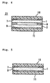
- FIG. 4 shows a cross-section of the laminated piezoelectric component shown in FIG. 1 .
- FIG. 5 is a cross-section showing another preferred embodiment of the present invention.
- FIG. 6 is a graph showing the change quantity of the center frequency when an adhesive having an elasticity modulus of 3000 MPa.
- FIG. 7 is a graph showing the change quantity of the center frequency when an adhesive having an elasticity modulus of 6000 MPa.
- FIG. 8 is a graph showing the relation between the change quantity of the center frequency and the mean thickness of the adhesive when an adhesive with an elastic modulus of 6000 MPa is used.
- FIG. 9 is a graph showing a time dependent change when an adhesive with an elastic modulus of 6000 MPa and a mean thickness of about 5 ⁇ m to about 15 ⁇ m is used.
- FIG. 10 is a graph showing a time dependent change when an adhesive with an elastic modulus of about 6000 MPa and a mean thickness of about 40 ⁇ m to about 45 ⁇ m is used.
- a laminated piezoelectric filter 21 preferably includes a piezoelectric substrates 1 and 2 , and cover substrates 10 and 11 defining vibration spaces by sandwiching the piezoelectric substrates 1 and 2 therebetween.
- the piezoelectric substrates 1 and 2 are preferably made of a lead titanate zirconate (PZT) based ceramic.
- PZT lead titanate zirconate
- quartz, LiTaO 3 other than PZT, and other suitable substrates may be used for the piezoelectric substrates 1 and 2 .
- the configuration of electrodes in the piezoelectric substrate will be described with reference to FIG. 2 .
- the electrode on the lower surface is illustrated by a downward projection.
- Vibration electrodes 3 a and 3 b, and a vibration electrode 3 c are provided on the upper and lower surfaces of the piezoelectric substrate 1 , respectively.
- a vibration of an energy trap-type longitudinal acoustic mode along the direction of thickness is generated at the portion where the vibration electrodes 3 a and 3 b are opposed to the vibration electrode 3 c, defining a first filter member 3 .
- the vibration electrodes 3 a and 3 b are electrically connected to lead electrodes 5 a and 5 b, while the vibration electrode 3 c is electrically connected to lead electrodes 5 c to 5 f.
- the lead electrode 5 b is opposed to the lead electrode 5 f through the piezoelectric substrate 1 defining a capacitor as a relay capacitance.
- Electrodes 6 a, 6 b and 6 c are provided on the upper surface of the piezoelectric substrate 1 such that electrodes 6 a, 6 b and 6 c overlap the lead electrodes 5 c, 5 d and 5 e, respectively, in the direction of thickness, and are electrically connected with the lead electrodes 5 c to 5 e.
- the electrodes 3 a to 3 c, 5 a to 5 f, and 6 a to 6 c are applied by sputtering, vacuum deposition of Ag or Cu, or other suitable methods.
- the areas surrounded by the dotted lines B and C on the piezoelectric substrate 1 are not polarized, while the remaining area is polarized in the direction of thickness of the substrate.
- the piezoelectric substrate 2 is preferably configured substantially similar to the piezoelectric substrate 1 and is oriented upside-down with respect to the orientation of the piezoelectric substrate 1 . Accordingly, an energy trap-type second filter having the longitudinal acoustic mode vibration along the direction of thickness, and a capacitor as a relay capacitance are also defined by the piezoelectric substrate 2 .
- the cover substrates 10 and 11 preferably include a ceramic material such as alumina, and a laminated body is defined by bonding the piezoelectric substrates 1 and 2 between the cover substrates 10 and 11 .
- the piezoelectric substrates 1 and 2 are laminated and bonded with an adhesive 8 along the direction of thickness.
- the cover substrate 10 is laminated and bonded on the top surface of the piezoelectric substrate 1 via an adhesive 7
- the cover substrate 11 is laminated and bonded on the bottom surface of the piezoelectric substrate 2 via an adhesive 9 .
- Cavities 7 a, 8 a and 9 a for defining vibration spaces of the first and second filters disposed on the piezoelectric substrates 1 and 2 are provided in these adhesives 7 to 9 .
- the adhesives 7 and 9 will be described in detail hereinafter.
- external electrodes are provided on the surface of the piezoelectric filter 21 and are preferably formed by sputtering, by coating and drying, or by other suitable methods.
- the lead electrode 5 a of the piezoelectric substrate 1 is connected to the external electrode 22 d, which defines an output terminal.
- the lead electrode 5 a from the piezoelectric substrate 2 is connected to the external electrode 22 a and defines an input terminal.
- the external electrode 22 b is connected to the electrode 6 b of the piezoelectric substrate 1 , and to the lead electrode 5 c and the electrode 6 a of the piezoelectric substrate 2 .
- the external electrode 22 c is connected to the lead electrode 5 b of the piezoelectric substrate 1 .
- the external electrode 22 e is connected to the electrode 6 a of the piezoelectric substrate 1 , and to the lead electrode 5 d and the electrode 6 b of the piezoelectric substrate 2 .
- the external electrode 22 f is connected to the lead electrode 5 b of the piezoelectric substrate 2 .
- the external electrodes 22 c and 22 f are connected with each other via an electrical continuity member 23 c
- the external electrodes 22 b and 22 e are connected with each other via an electrical continuity member 23 a.
- the electrical continuity member 23 c includes an extension electrode 23 b, and isolation between the input and output terminals is enhanced by disposing this extension electrode 23 b between the input-output external electrodes 22 a and 22 d.
- FIG. 4 shows a cross-section of the piezoelectric filter 21 obtained, wherein the vibration electrode and external electrodes are not illustrated.
- the adhesives 7 and 9 will be described in detail hereinafter.
- the center frequency Fo changes before and after reflowing because of the heat applied to the piezoelectric substrates 1 and 2 , when the piezoelectric filter 21 is subjected to a high temperature heat treatment such as reflowing.
- the piezoelectric substrates 1 and 2 also experience a stress from the cover substrates 10 and 11 , and from the adhesives 7 and 9 , due to differences of thermal expansion coefficients.
- the piezoelectric substrates 1 and 2 are made of a ceramic substrate, the thermal expansion coefficient increased in the order of the piezoelectric substrates 1 and 2 , the cover substrates 10 and 11 , and the adhesives 7 and 9 .
- the stress imparted from the cover substrates 10 and 11 become dominant among the stresses applied to the piezoelectric substrates 1 and 2 , when the adhesives 7 and 9 have a large elasticity modulus, or when the adhesives 7 and 9 are thin. Since expansion of the cover substrates 10 and 11 turns out to be larger than expansion of the piezoelectric substrates 1 and 2 by the heat of reflowing, the piezoelectric substrates 1 and 2 experience a compression stress from the cover substrates 10 and 11 , thereby the center frequency Fo shifts to the low frequency side.
- the adhesives 7 and 9 have a small elasticity modulus, or when the adhesives 7 and 9 are thick, on the other hand, the stress imparted from the cover substrates 10 and 11 is absorbed by the adhesives 7 and 9 . As a result, the stress imparted from the adhesives 7 and 9 becomes dominant among the stresses applied to the piezoelectric substrates 1 and 2 . Since the adhesives 7 and 9 are disposed around the vibration electrodes 3 a and 3 b of the piezoelectric substrates 1 and 2 as shown in FIG.
- vibration portions of the piezoelectric substrates 1 and 2 on which the vibration electrodes 3 a and 3 b are disposed experience a tensile stress from the adhesives 7 and 9 , when the adhesives 7 and 9 having a larger thermal expansion coefficient start contracting after being subjected to reflowing. Consequently, the center frequency shifts to the higher frequency side.
- the change of the center frequency Fo can be controlled by controlling the stress imparted to the piezoelectric substrates 1 and 2 by changing the elasticity modulus and thickness of the adhesives 7 and 9 .
- the change of the center frequency Fo by the heat imparted to the piezoelectric substrates 1 and 2 during reflowing is effectively canceled by the change of the center frequency Fo caused by the synthesized stress imparted to the piezoelectric substrates 1 and 2 from the cover substrates 10 and 11 , and from the adhesives 7 and 9 , by appropriately selecting the elasticity modulus and thickness of the adhesives 7 and 9 . Consequently, a laminated piezoelectric filter 21 that is able to minimize the change quantity of the center frequency Fo before and after the high temperature heat treatment such as reflowing can be obtained.
- adhesives 7 and 9 having an elasticity modulus c and thickness b 2 are selected so that the calculated value by the following equation is approximately zero:
- a 1 (/°C.) and b 1 ( ⁇ m) denote the thermal expansion coefficient and thickness of the cover substrates 10 and 11 , respectively
- a 2 (/°C.), b 2 ( ⁇ m) and c (MPa) denote the thermal expansion coefficient, thickness and elasticity modulus of the adhesives 7 and 9 , respectively
- a 3 (/°C.) and b 3 ( ⁇ m) denote the thermal expansion coefficient and thickness of the piezoelectric substrates 1 and 2 . It is preferable that the values that makes the calculated value by the equation (1) to fall within a range of about 0 ⁇ 1.0 ⁇ 10 ⁇ 4 are selected.
- the stress imparted to the piezoelectric substrates 1 and 2 from the cover substrates 10 and 11 is absorbed by the adhesives 7 and 9 , the stress only contains a stress component that is imparted to the piezoelectric substrates 1 and 2 from the adhesives 7 and 9 . Accordingly, the piezoelectric substrates 1 and 2 always experience an approximately constant stress, thereby reducing the change quantity of the center frequency Fo before and after reflowing as well as distribution thereof. More practically, the terms containing the parameters a 1 and b 1 related to the cover substrates 10 and 11 is diminished, in order to minimize the influence of the cover substrates 10 and 11 in the equation (1).
- an adhesive 7 and 9 having an elasticity modulus c and thickness b 2 in which the value of b 2 /c 2 as a coefficient of the equation exp[ ⁇ (b 2 /c 2 ) ⁇ 10 ⁇ 7 ] satisfies the following equation (2), is selected:
- the laminated piezoelectric component according to the present invention is not restricted to preferred embodiments as set forth above, but is variable within a range that does not alter the spirit of the present invention.
- the number of the piezoelectric substrates is not necessarily restricted to two substrates, but one piezoelectric substrate 1 may be sandwiched and sealed by two cover substrates 10 and 11 . While recesses for defining vibration spaces are provided on the cover substrates in the piezoelectric component in preferred embodiments as set forth above, such recesses may be omitted and the vibration space may be provided by taking advantage of the thickness of the adhesive.
- Examples of the piezoelectric filter 21 as shown in FIGS. 1 to 3 was manufactured using the cover substrates 10 and 11 having a thickness of about 500 ⁇ m and the piezoelectric substrate 1 and 2 having a thickness of about 200 ⁇ m, while using two kinds of adhesives having elasticity moduli of about 3000 MPa and about 6000 MPa as the adhesives 7 and 9 .
- the thermal expansion coefficients of the cover substrates 10 and 11 , and of the piezoelectric substrate 1 and 2 were about 7.8 ⁇ 10 ⁇ 6 /°C. and 2.0 ⁇ 10 ⁇ 6 /°C., respectively.
- the thermal expansion coefficients of the adhesives 7 and 9 were about 6.3 ⁇ 10 ⁇ 5 /°C. and 4.8 ⁇ 10 ⁇ 5 /°C. for those having an elasticity modulus of about 3000 MPa and about 6000 MPa, respectively.
- the value of the equation (1) should be close to zero for reducing the change quantity of the center frequency Fo before and after reflowing. Accordingly, the target value of the thickness b 2 of the adhesives 7 and 9 may be adjusted to about 6 ⁇ m for limiting the value of the equation (1) within a range of about 0 ⁇ 1.0 ⁇ 10 ⁇ 4 , when the adhesives 7 and 9 have an elasticity modulus c of about 3000 MPa. Likewise, the target value of the thickness b 2 of the adhesives 7 and 9 may be adjusted to 12 ⁇ m when the adhesives 7 and 9 have an elasticity modulus c of about 6000 MPa.
- FIGS. 6 and 7 are the graphs showing the relation between the change quantities of the center frequency Fo before and after reflowing (the change quantity after 24 hours' reflowing) and the thickness b 2 of the adhesives 7 and 9 when the thickness b 2 of the adhesives 7 and 9 is in the range of about 5 ⁇ m to 15 ⁇ m, wherein the elasticity moduli are about 3000 MPa and about 6000 MPa in FIG. 6 and FIG. 7, respectively.
- the graphs show that the change quantity of the center frequency is approximately zero at the target thicknesses b 2 of about 6 ⁇ m and about 12 ⁇ m for the adhesives 7 and 9 having an elasticity moduli c of about 3000 MPa and about 6000 MPa, respectively.
- the equation (2) should be satisfied in order to minimize the change quantity of center frequency Fo before and after reflowing. Accordingly, the thickness b 2 of the adhesives 7 and 9 should be adjusted to about 4.5 ⁇ m or more in the equation (2), when the adhesives 7 and 9 have an elasticity modulus c of about 3000 MPa. The thickness b 2 should be adjusted, on the other hand, to about 18 ⁇ m or more when the elasticity modulus c is about 6000 MPa. FIG.
- FIGS. 8 is a graph showing the change quantity of the center frequency Fo before and after reflowing (the change quantity after 24 hours' reflowing) of the sample groups A and B prepared using the adhesives with a thickness b 2 of about 40 ⁇ m to about 45 ⁇ m and with a thickness b 2 of about 5 ⁇ m to about 15 ⁇ m, respectively, wherein the adhesives 7 and 9 having an elasticity modulus c of about 6000 MPa were used.
- Ten samples were randomly selected from the sample group B having a thickness b 2 of about 5 ⁇ m to about 15 ⁇ m, and ten samples were randomly selected from the sample group A having a thickness b 2 of about 40 ⁇ m to 45 ⁇ m.
- FIG. 9 and 10 are the graphs showing the experimental results when the maximum values, minimum values and averaged values of the time-dependent change quantities of the center frequency Fo were measured with respect to the sample groups B and A, respectively. It can be understood from the comparison between FIG. 9 and FIG. 10 that distribution of the change quantity of the center frequency Fo is suppressed by increasing the thickness b 2 .
- the piezoelectric substrate only experiences the component of the synthesized stress imparted to the piezoelectric substrate form the adhesives, when the stress imparted to the piezoelectric substrate from the cover substrates is absorbed by the adhesives. Therefore, the piezoelectric substrate always experiences an approximately constant stress, thereby allowing the change quantity of the resonance before and after reflowing to be minimized and the distribution thereof to be minimized.
Abstract
A laminated piezoelectric component or filter is arranged such that a change in the resonance frequency before and after a high temperature heat treatment such as reflowing is minimized and the distribution of the resonance frequency is also minimized. The laminated filter includes a piezoelectric substrate having a vibrating electrode provided on the back surface of the substrate, cover substrates, and adhesives located between the piezoelectric substrate and cover substrate. The change in the center frequency Fo due to the heat applied to the piezoelectric substrate during reflowing is canceled by the change of the center frequency Fo caused by the synthesized stress imparted to the piezoelectric substrates from the cover substrates and adhesives.
Description
1. Field of the Invention
The present invention relates to a laminated piezoelectric component, particularly to a laminated piezoelectric component for use with oscillators and filters.
2. Description of the Related Art
Conventional piezoelectric components include piezoelectric ceramic substrates having vibrating electrodes provided on a surface thereof. The vibrating electrodes are sealed by sandwiching them between two cover substrates via adhesives. Various adhesives have been used depending upon the structure and characteristics of the piezoelectric component and the bonding strength of the adhesive. The thickness of the adhesive is relatively small and the specific thickness is determined based upon the sealing property of the vibration space and prevention of breakage of external electrodes.
When the piezoelectric component is subjected to a high temperature heat treatment, such as reflowing, the crystalline structure of a portion of the piezoelectric ceramic substrate is altered by the heat of reflowing, thereby a resonance frequency Fo (the center frequency of a piezoelectric filter, or the oscillation frequency of an oscillator) differ before and after reflowing. Accordingly, a correction should be provided to account for the change of the resonance frequency Fo due to the heat of reflowing, otherwise the resonance frequency Fo of the piezoelectric component after reflowing varies greatly.
In order to overcome the problems described above, preferred embodiments of the present invention provide a laminated piezoelectric component which minimizes the degree of change of the resonance frequency before and after being subjected to a high temperature heat treatment, such as reflowing, and further minimizes the distribution of the resonance frequency.
Preferred embodiments of the present invention provide a laminated piezoelectric component having piezoelectric substrates on the surface of which vibration electrodes are provided, cover substrates defining a laminated body together with the piezoelectric substrates, and adhesives located between the piezoelectric substrates and the cover substrates to bond the piezoelectric substrates to the cover substrates, wherein the elasticity modulus and thickness of the adhesive are determined so that a change in the resonance frequency due to the heat applied to the piezoelectric substrate is canceled by the change in the resonance frequency caused by a synthesized stress that is imparted on the piezoelectric substrate from the cover substrate and adhesive.
The resonance frequency described herein refers to a center frequency in the case of a piezoelectric filter and the oscillation frequency in the case of an oscillator.
The synthesized stress imparted on the piezoelectric substrate from the cover substrate and adhesive is controlled by the modulus of elasticity and thickness of the adhesive. Practically, the modulus of elasticity c and the thickness b2 of the adhesive are determined such that the calculated value using the following equation is approximately zero:
where a1 (/°C.) and b1 (μm) denote the thermal expansion coefficient and thickness of the cover substrate, respectively, a2 (/°C.), b2 (μm) and c (MPa) denote the thermal expansion coefficient, thickness and modulus of elasticity of the adhesive, respectively, and a3 (/°C.) and b3 (μm) denote the thermal expansion coefficient and thickness of the piezoelectric substrate.
Consequently, the change of the resonance frequency due to the synthesized stress imparted on the piezoelectric substrate from the cover substrate and adhesive cancels the change of the resonance frequency due to the:heat imparted on the piezoelectric substrate. As a result, the degree of change of the resonance frequency before and after a :high temperature heat treatment, such as reflowing, is minimized.
The stress imparted on the piezoelectric substrate from the cover substrate is absorbed by the adhesive in the laminated piezoelectric component according to preferred embodiments of the present invention. In other words, the modulus of elasticity c and the thickness b2 of the adhesive are determined such that the synthesized stress imparted on the piezoelectric substrate includes only the stress component imparted on the piezoelectric substrate from the adhesive. Actually, the value of (b2/c2), which is a coefficient of exp[−(b2/c2)×107], is determined to be 5.0×10⁻⁷ or more in the equation of a2×b2−a3×b3−a1×b1×exp[−(b2/c2)×107]. This unique arrangement eliminates the influence of the cover substrate, thus allowing only a synthesized stress having a given amount of stress from the adhesive to be imparted on the piezoelectric substrate. Accordingly, the degree of change of the resonance frequency before and after a high temperature heat treatment, such as reflowing, is greatly reduced and minimized. Further, the distribution of the resonance frequency is greatly reduced and minimized.
Other features, elements, characteristics and advantages of the present invention will become apparent from the detailed description of preferred embodiments thereof with reference to the drawings attached hereto.
FIG. 1 is an exploded perspective view showing one preferred embodiment of the laminated piezoelectric substrate according to the present invention.
FIG. 2 is a perspective view showing the structure of the electrodes used for the laminated piezoelectric component shown in FIG. 1.
FIG. 3A shows a plane view of the laminated piezoelectric component shown in FIG. 1.
FIG. 3B shows a left-side view of the laminated piezoelectric component shown in FIG. 1.
FIG. 3C shows a bottom view of the laminated piezoelectric component shown in FIG. 1.
FIG. 4 shows a cross-section of the laminated piezoelectric component shown in FIG. 1.
FIG. 5 is a cross-section showing another preferred embodiment of the present invention.
FIG. 6 is a graph showing the change quantity of the center frequency when an adhesive having an elasticity modulus of 3000 MPa.
FIG. 7 is a graph showing the change quantity of the center frequency when an adhesive having an elasticity modulus of 6000 MPa.
FIG. 8 is a graph showing the relation between the change quantity of the center frequency and the mean thickness of the adhesive when an adhesive with an elastic modulus of 6000 MPa is used.
FIG. 9 is a graph showing a time dependent change when an adhesive with an elastic modulus of 6000 MPa and a mean thickness of about 5 μm to about 15 μm is used.
FIG. 10 is a graph showing a time dependent change when an adhesive with an elastic modulus of about 6000 MPa and a mean thickness of about 40 μm to about 45 μm is used.
In the following, preferred embodiments of the laminated piezoelectric component according to the present invention will be described with reference to the accompanying drawings. Each preferred embodiment is described below with reference to a filter as an example of a suitable component. However, preferred embodiments of the present invention may also be an oscillator, or other suitable electronic components.
As shown in FIG. 1, a laminated piezoelectric filter 21 preferably includes a piezoelectric substrates 1 and 2, and cover substrates 10 and 11 defining vibration spaces by sandwiching the piezoelectric substrates 1 and 2 therebetween. The piezoelectric substrates 1 and 2 are preferably made of a lead titanate zirconate (PZT) based ceramic. However, quartz, LiTaO3 other than PZT, and other suitable substrates may be used for the piezoelectric substrates 1 and 2.
The configuration of electrodes in the piezoelectric substrate will be described with reference to FIG. 2. The electrode on the lower surface is illustrated by a downward projection. Vibration electrodes 3 a and 3 b, and a vibration electrode 3 c are provided on the upper and lower surfaces of the piezoelectric substrate 1, respectively. A vibration of an energy trap-type longitudinal acoustic mode along the direction of thickness is generated at the portion where the vibration electrodes 3 a and 3 b are opposed to the vibration electrode 3 c, defining a first filter member 3.
The vibration electrodes 3 a and 3 b are electrically connected to lead electrodes 5 a and 5 b, while the vibration electrode 3 c is electrically connected to lead electrodes 5 c to 5 f. The lead electrode 5 b is opposed to the lead electrode 5 f through the piezoelectric substrate 1 defining a capacitor as a relay capacitance. Electrodes 6 a, 6 b and 6 c are provided on the upper surface of the piezoelectric substrate 1 such that electrodes 6 a, 6 b and 6 c overlap the lead electrodes 5 c, 5 d and 5 e, respectively, in the direction of thickness, and are electrically connected with the lead electrodes 5 c to 5 e. The electrodes 3 a to 3 c, 5 a to 5 f, and 6 a to 6 c are applied by sputtering, vacuum deposition of Ag or Cu, or other suitable methods. The areas surrounded by the dotted lines B and C on the piezoelectric substrate 1 are not polarized, while the remaining area is polarized in the direction of thickness of the substrate.
Returning to FIG. 1, the piezoelectric substrate 2 is preferably configured substantially similar to the piezoelectric substrate 1 and is oriented upside-down with respect to the orientation of the piezoelectric substrate 1. Accordingly, an energy trap-type second filter having the longitudinal acoustic mode vibration along the direction of thickness, and a capacitor as a relay capacitance are also defined by the piezoelectric substrate 2.
The cover substrates 10 and 11 preferably include a ceramic material such as alumina, and a laminated body is defined by bonding the piezoelectric substrates 1 and 2 between the cover substrates 10 and 11. The piezoelectric substrates 1 and 2 are laminated and bonded with an adhesive 8 along the direction of thickness. The cover substrate 10 is laminated and bonded on the top surface of the piezoelectric substrate 1 via an adhesive 7, while the cover substrate 11 is laminated and bonded on the bottom surface of the piezoelectric substrate 2 via an adhesive 9. Cavities 7 a, 8 a and 9 a for defining vibration spaces of the first and second filters disposed on the piezoelectric substrates 1 and 2 are provided in these adhesives 7 to 9. The adhesives 7 and 9 will be described in detail hereinafter.
As shown in FIGS. 3A, 3B and 3C, external electrodes are provided on the surface of the piezoelectric filter 21 and are preferably formed by sputtering, by coating and drying, or by other suitable methods. The lead electrode 5 a of the piezoelectric substrate 1 is connected to the external electrode 22 d, which defines an output terminal. Likewise, the lead electrode 5 a from the piezoelectric substrate 2 is connected to the external electrode 22 a and defines an input terminal. The external electrode 22 b is connected to the electrode 6 b of the piezoelectric substrate 1, and to the lead electrode 5 c and the electrode 6 a of the piezoelectric substrate 2. The external electrode 22 c is connected to the lead electrode 5 b of the piezoelectric substrate 1. The external electrode 22 e is connected to the electrode 6 a of the piezoelectric substrate 1, and to the lead electrode 5 d and the electrode 6 b of the piezoelectric substrate 2. The external electrode 22 f is connected to the lead electrode 5 b of the piezoelectric substrate 2. As shown in FIG. 3C, the external electrodes 22 c and 22 f are connected with each other via an electrical continuity member 23 c, and the external electrodes 22 b and 22 e are connected with each other via an electrical continuity member 23 a. The electrical continuity member 23 c includes an extension electrode 23 b, and isolation between the input and output terminals is enhanced by disposing this extension electrode 23 b between the input-output external electrodes 22 a and 22 d.
A two-step piezoelectric filter 21 having two filter members is obtained as described above. FIG. 4 shows a cross-section of the piezoelectric filter 21 obtained, wherein the vibration electrode and external electrodes are not illustrated.
The adhesives 7 and 9 will be described in detail hereinafter. The center frequency Fo changes before and after reflowing because of the heat applied to the piezoelectric substrates 1 and 2, when the piezoelectric filter 21 is subjected to a high temperature heat treatment such as reflowing. The piezoelectric substrates 1 and 2 also experience a stress from the cover substrates 10 and 11, and from the adhesives 7 and 9, due to differences of thermal expansion coefficients. When the piezoelectric substrates 1 and 2 are made of a ceramic substrate, the thermal expansion coefficient increased in the order of the piezoelectric substrates 1 and 2, the cover substrates 10 and 11, and the adhesives 7 and 9. Accordingly, the stress imparted from the cover substrates 10 and 11 become dominant among the stresses applied to the piezoelectric substrates 1 and 2, when the adhesives 7 and 9 have a large elasticity modulus, or when the adhesives 7 and 9 are thin. Since expansion of the cover substrates 10 and 11 turns out to be larger than expansion of the piezoelectric substrates 1 and 2 by the heat of reflowing, the piezoelectric substrates 1 and 2 experience a compression stress from the cover substrates 10 and 11, thereby the center frequency Fo shifts to the low frequency side.
When the adhesives 7 and 9 have a small elasticity modulus, or when the adhesives 7 and 9 are thick, on the other hand, the stress imparted from the cover substrates 10 and 11 is absorbed by the adhesives 7 and 9. As a result, the stress imparted from the adhesives 7 and 9 becomes dominant among the stresses applied to the piezoelectric substrates 1 and 2. Since the adhesives 7 and 9 are disposed around the vibration electrodes 3 a and 3 b of the piezoelectric substrates 1 and 2 as shown in FIG. 1, vibration portions of the piezoelectric substrates 1 and 2 on which the vibration electrodes 3 a and 3 b are disposed experience a tensile stress from the adhesives 7 and 9, when the adhesives 7 and 9 having a larger thermal expansion coefficient start contracting after being subjected to reflowing. Consequently, the center frequency shifts to the higher frequency side. In other words, the change of the center frequency Fo can be controlled by controlling the stress imparted to the piezoelectric substrates 1 and 2 by changing the elasticity modulus and thickness of the adhesives 7 and 9.
Accordingly, the change of the center frequency Fo by the heat imparted to the piezoelectric substrates 1 and 2 during reflowing is effectively canceled by the change of the center frequency Fo caused by the synthesized stress imparted to the piezoelectric substrates 1 and 2 from the cover substrates 10 and 11, and from the adhesives 7 and 9, by appropriately selecting the elasticity modulus and thickness of the adhesives 7 and 9. Consequently, a laminated piezoelectric filter 21 that is able to minimize the change quantity of the center frequency Fo before and after the high temperature heat treatment such as reflowing can be obtained.
Actually, adhesives 7 and 9 having an elasticity modulus c and thickness b2 are selected so that the calculated value by the following equation is approximately zero:
where a1 (/°C.) and b1 (μm) denote the thermal expansion coefficient and thickness of the cover substrates 10 and 11, respectively, a2 (/°C.), b2 (μm) and c (MPa) denote the thermal expansion coefficient, thickness and elasticity modulus of the adhesives 7 and 9, respectively, and a3 (/°C.) and b3 (μm) denote the thermal expansion coefficient and thickness of the piezoelectric substrates 1 and 2. It is preferable that the values that makes the calculated value by the equation (1) to fall within a range of about 0±1.0×10⁻⁴ are selected.
When the stress imparted to the piezoelectric substrates 1 and 2 from the cover substrates 10 and 11 is absorbed by the adhesives 7 and 9, the stress only contains a stress component that is imparted to the piezoelectric substrates 1 and 2 from the adhesives 7 and 9. Accordingly, the piezoelectric substrates 1 and 2 always experience an approximately constant stress, thereby reducing the change quantity of the center frequency Fo before and after reflowing as well as distribution thereof. More practically, the terms containing the parameters a1 and b1 related to the cover substrates 10 and 11 is diminished, in order to minimize the influence of the cover substrates 10 and 11 in the equation (1). That is, an adhesive 7 and 9 having an elasticity modulus c and thickness b2, in which the value of b2/c2 as a coefficient of the equation exp[−(b2/c2)×10−7] satisfies the following equation (2), is selected:
The laminated piezoelectric component according to the present invention is not restricted to preferred embodiments as set forth above, but is variable within a range that does not alter the spirit of the present invention. The number of the piezoelectric substrates is not necessarily restricted to two substrates, but one piezoelectric substrate 1 may be sandwiched and sealed by two cover substrates 10 and 11. While recesses for defining vibration spaces are provided on the cover substrates in the piezoelectric component in preferred embodiments as set forth above, such recesses may be omitted and the vibration space may be provided by taking advantage of the thickness of the adhesive.
Examples of the piezoelectric filter 21 as shown in FIGS. 1 to 3 was manufactured using the cover substrates 10 and 11 having a thickness of about 500 μm and the piezoelectric substrate 1 and 2 having a thickness of about 200 μm, while using two kinds of adhesives having elasticity moduli of about 3000 MPa and about 6000 MPa as the adhesives 7 and 9. The thermal expansion coefficients of the cover substrates 10 and 11, and of the piezoelectric substrate 1 and 2 were about 7.8×10⁻⁶/°C. and 2.0×10⁻⁶/°C., respectively. The thermal expansion coefficients of the adhesives 7 and 9 were about 6.3×10⁻⁵/°C. and 4.8×10⁻⁵/°C. for those having an elasticity modulus of about 3000 MPa and about 6000 MPa, respectively.
The value of the equation (1) should be close to zero for reducing the change quantity of the center frequency Fo before and after reflowing. Accordingly, the target value of the thickness b2 of the adhesives 7 and 9 may be adjusted to about 6 μm for limiting the value of the equation (1) within a range of about 0±1.0×10⁻⁴, when the adhesives 7 and 9 have an elasticity modulus c of about 3000 MPa. Likewise, the target value of the thickness b2 of the adhesives 7 and 9 may be adjusted to 12 μm when the adhesives 7 and 9 have an elasticity modulus c of about 6000 MPa.
FIGS. 6 and 7 are the graphs showing the relation between the change quantities of the center frequency Fo before and after reflowing (the change quantity after 24 hours' reflowing) and the thickness b2 of the adhesives 7 and 9 when the thickness b2 of the adhesives 7 and 9 is in the range of about 5 μm to 15 μm, wherein the elasticity moduli are about 3000 MPa and about 6000 MPa in FIG. 6 and FIG. 7, respectively. The graphs show that the change quantity of the center frequency is approximately zero at the target thicknesses b2 of about 6 μm and about 12 μm for the adhesives 7 and 9 having an elasticity moduli c of about 3000 MPa and about 6000 MPa, respectively.
The equation (2) should be satisfied in order to minimize the change quantity of center frequency Fo before and after reflowing. Accordingly, the thickness b2 of the adhesives 7 and 9 should be adjusted to about 4.5 μm or more in the equation (2), when the adhesives 7 and 9 have an elasticity modulus c of about 3000 MPa. The thickness b2 should be adjusted, on the other hand, to about 18 μm or more when the elasticity modulus c is about 6000 MPa. FIG. 8 is a graph showing the change quantity of the center frequency Fo before and after reflowing (the change quantity after 24 hours' reflowing) of the sample groups A and B prepared using the adhesives with a thickness b2 of about 40 μm to about 45 μm and with a thickness b2 of about 5 μm to about 15 μm, respectively, wherein the adhesives 7 and 9 having an elasticity modulus c of about 6000 MPa were used. Ten samples were randomly selected from the sample group B having a thickness b2 of about 5 μm to about 15 μm, and ten samples were randomly selected from the sample group A having a thickness b2 of about 40 μm to 45 μm. FIGS. 9 and 10 are the graphs showing the experimental results when the maximum values, minimum values and averaged values of the time-dependent change quantities of the center frequency Fo were measured with respect to the sample groups B and A, respectively. It can be understood from the comparison between FIG. 9 and FIG. 10 that distribution of the change quantity of the center frequency Fo is suppressed by increasing the thickness b2.
As is evident from the foregoing descriptions, change of the resonance frequency caused by the heat imparted to the piezoelectric substrate during reflowing is effectively canceled by preferred embodiments of the present invention by the change of the resonance frequency caused by the synthesized stress imparted to the piezoelectric substrate from the cover substrates and adhesives, by adjusting the elasticity modulus and thickness of the adhesives. Consequently, a laminated piezoelectric component, in which the change quantity of the center frequency before and after a high temperature heat treatment such as reflowing is minimized, can be obtained. In addition, the piezoelectric substrate only experiences the component of the synthesized stress imparted to the piezoelectric substrate form the adhesives, when the stress imparted to the piezoelectric substrate from the cover substrates is absorbed by the adhesives. Therefore, the piezoelectric substrate always experiences an approximately constant stress, thereby allowing the change quantity of the resonance before and after reflowing to be minimized and the distribution thereof to be minimized.
While preferred embodiments of the invention have been disclosed, various modes of carrying out the principles disclosed herein are contemplated as being within the scope of the following claims. Therefore, it is understood that the scope of the invention is not to be limited except as otherwise set forth in the claims.
Claims (17)
1. A laminated piezoelectric component comprising:
a plurality of piezoelectric substrates having vibration electrodes disposed on a surface thereof;
a plurality of cover substrates arranged in a stack with the plurality of piezoelectric substrates so as to define a laminated body together with the piezoelectric substrates; and
adhesives located between the piezoelectric substrates and the cover substrates so as to bond the piezoelectric substrates to the cover substrates;
wherein an elasticity modulus and thickness of the adhesives are determined so that a change of the resonance frequency, caused by heat applied to the piezoelectric substrate is canceled by a change of the resonance frequency caused by a synthesized stress that is imparted to the piezoelectric substrate from the cover substrates and adhesives; and
the value calculated by the following equation is approximately zero:
where a1 (/°C.) and be (μm) denote the thermal expansion coefficient and thickness of the cover substrates, respectively, a2 (/°C.), b2 (μm) and c (MPa) denote the thermal expansion coefficient, thickness and elasticity modulus of the adhesives, respectively, and a3 (/°C.) and b3 (μm) denote the thermal expansion coefficient and thickness of the piezoelectric substrates.
2. A laminated piezoelectric component according to claim 1 , wherein the adhesives are arranged such that the stress imparted to the piezoelectric substrate from the cover substrate is absorbed by the adhesive so that the synthesized stress imparted to the piezoelectric substrate only contains a stress component imparted from the adhesive to the piezoelectric substrate.
3. A laminated piezoelectric component according to claim 1 , wherein the adhesives are arranged to have an elasticity modulus c and thickness b2, in which the value of b2/c2 as a coefficient of the equation exp[−(b2/c2)×10−7] satisfies the equation (b2/c2)×5.0×10−7 is selected.
4. A laminated piezoelectric component according to claim 1 , wherein the value of b2/c2 is 5.0×10⁻⁷ or more.
5. A laminated piezoelectric component according to claim 1 , wherein the plurality of piezoelectric substrates includes at least two piezoelectric substrates.
6. A laminated piezoelectric component according to claim 1 , wherein the cover substrates includes at least two piezoelectric substrates.
7. A laminated piezoelectric component according to claim 1 , wherein the plurality of piezoelectric substrates are arranged to be sandwiched by the plurality of cover substrates.
8. A laminated piezoelectric component according to claim 1 , wherein the plurality of piezoelectric substrates are made of at least one of lead titanate zirconate ceramic, quartz and LiTaO3.
9. A laminated piezoelectric component according to claim 1 , wherein the plurality of piezoelectric substrates, the plurality of cover members and the plurality of vibration electrodes are arranged to define a plurality of filters.
10. A laminated piezoelectric component according to claim 9 , wherein the plurality of filters are energy-trap longitudinal acoustic mode filters.
11. A laminated piezoelectric component according to claim 9 , wherein cavities defining vibration spaces of the plurality of filters are provided in the adhesives.
12. A laminated piezoelectric component according to claim 1 , wherein portions of the piezoelectric substrates are polarized in a thickness direction thereof.
13. A laminated piezoelectric component according to claim 1 , wherein the stress imparted from the adhesives is greater than other stresses applied to the piezoelectric substrate.
14. A laminated piezoelectric component according to claim 1 , wherein the adhesives are arranged around the vibration electrodes on the piezoelectric substrates such that vibration portions of the piezoelectric substrates on which the vibration electrodes are disposed experience a tensile stress imparted from the adhesives.
15. A laminated piezoelectric component according to claim 1 , wherein the adhesives have a larger thermal expansion coefficient than the piezoelectric substrates.
16. A laminated piezoelectric component according to claim 1 , wherein the adhesives are arranged to impart stress to the piezoelectric substrates such that the center frequency shifts to the higher frequency side.
17. A laminated piezoelectric component according to claim 1 , wherein the adhesives are arranged to cause the piezoelectric substrates to experience a substantially constant stress.
Applications Claiming Priority (2)
| Application Number | Priority Date | Filing Date | Title |
|---|---|---|---|
| JP14554499A JP3402256B2 (en) | 1999-05-25 | 1999-05-25 | Laminated piezoelectric components |
| JP11-145544 | 1999-05-25 |
Publications (1)
| Publication Number | Publication Date |
|---|---|
| US6433654B1 true US6433654B1 (en) | 2002-08-13 |
Family
ID=15387646
Family Applications (1)
| Application Number | Title | Priority Date | Filing Date |
|---|---|---|---|
| US09/574,884 Expired - Lifetime US6433654B1 (en) | 1999-05-25 | 2000-05-19 | Laminated piezoelectric component |
Country Status (4)
| Country | Link |
|---|---|
| US (1) | US6433654B1 (en) |
| JP (1) | JP3402256B2 (en) |
| CN (1) | CN1156967C (en) |
| DE (1) | DE10025337B4 (en) |
Cited By (5)
| Publication number | Priority date | Publication date | Assignee | Title |
|---|---|---|---|---|
| US20080137270A1 (en) * | 2006-12-12 | 2008-06-12 | Matsushita Electric Industrial Co., Ltd. | Electronic element package and method of manufacturing the same |
| US20090128375A1 (en) * | 2007-11-16 | 2009-05-21 | Diehl Ako Stiftung & Co. Kg | Control Apparatus Having at Least One Pushbutton Switch and Domestic Appliance Having a Control Apparatus |
| CN103210585A (en) * | 2010-11-16 | 2013-07-17 | 株式会社村田制作所 | Layered bandpass filter |
| US20130334933A1 (en) * | 2011-03-01 | 2013-12-19 | Murata Manufacturing Co., Ltd. | Piezoelectric element and piezoelectric device using the same |
| CN104756403B (en) * | 2013-03-28 | 2018-04-24 | 株式会社村田制作所 | LC filter cells body and LC wave filters |
Families Citing this family (3)
| Publication number | Priority date | Publication date | Assignee | Title |
|---|---|---|---|---|
| JP3538710B2 (en) * | 2000-06-27 | 2004-06-14 | 株式会社村田製作所 | Piezoelectric filter and method of manufacturing the same |
| JP4983881B2 (en) * | 2009-09-28 | 2012-07-25 | 株式会社村田製作所 | Multilayer bandpass filter |
| JP6547707B2 (en) * | 2016-07-29 | 2019-07-24 | 株式会社村田製作所 | Layered filter |
Citations (7)
| Publication number | Priority date | Publication date | Assignee | Title |
|---|---|---|---|---|
| US3665225A (en) * | 1970-08-28 | 1972-05-23 | Iit Res Inst | Hybrid surface-wave transducer |
| US5406230A (en) * | 1992-02-25 | 1995-04-11 | Murata Manufacturing Co., Ltd. | Chip type oscillator and oscillation circuit using this oscillator |
| US5543106A (en) * | 1993-12-29 | 1996-08-06 | Murata Manufacturing Co., Ltd. | Method of polarizing piezoelectric ceramic substrate |
| JPH10284985A (en) * | 1997-04-01 | 1998-10-23 | Murata Mfg Co Ltd | Piezoelectric filter |
| US5844348A (en) * | 1995-06-06 | 1998-12-01 | Murata Manufacturing Co., Ltd. | Piezoelectric resonant part and method of manufacturing the same |
| US6011451A (en) * | 1997-04-01 | 2000-01-04 | Murata Manufacturing Co., Ltd. | Chip type piezoelectric filter having internal common electrodes or a shield electrode |
| US6160462A (en) * | 1997-08-12 | 2000-12-12 | Ngk Spark Plug Co., Ltd. | Energy trapping type piezoelectric filter with identical piezoelectric substrates |
Family Cites Families (1)
| Publication number | Priority date | Publication date | Assignee | Title |
|---|---|---|---|---|
| US5473216A (en) * | 1994-06-29 | 1995-12-05 | Motorola, Inc. | Piezoelectric device for controlling the frequency-temperature shift of piezoelectric crystals and method of making same |
-
1999
- 1999-05-25 JP JP14554499A patent/JP3402256B2/en not_active Expired - Lifetime
-
2000
- 2000-05-19 US US09/574,884 patent/US6433654B1/en not_active Expired - Lifetime
- 2000-05-23 DE DE10025337A patent/DE10025337B4/en not_active Expired - Lifetime
- 2000-05-25 CN CNB00117682XA patent/CN1156967C/en not_active Expired - Lifetime
Patent Citations (8)
| Publication number | Priority date | Publication date | Assignee | Title |
|---|---|---|---|---|
| US3665225A (en) * | 1970-08-28 | 1972-05-23 | Iit Res Inst | Hybrid surface-wave transducer |
| US5406230A (en) * | 1992-02-25 | 1995-04-11 | Murata Manufacturing Co., Ltd. | Chip type oscillator and oscillation circuit using this oscillator |
| US5543106A (en) * | 1993-12-29 | 1996-08-06 | Murata Manufacturing Co., Ltd. | Method of polarizing piezoelectric ceramic substrate |
| US5844348A (en) * | 1995-06-06 | 1998-12-01 | Murata Manufacturing Co., Ltd. | Piezoelectric resonant part and method of manufacturing the same |
| JPH10284985A (en) * | 1997-04-01 | 1998-10-23 | Murata Mfg Co Ltd | Piezoelectric filter |
| US6002308A (en) * | 1997-04-01 | 1999-12-14 | Murata Manufacturing Co., Ltd. | Piezoelectric filter with a capacitor on a substrate having an unpolarized portion |
| US6011451A (en) * | 1997-04-01 | 2000-01-04 | Murata Manufacturing Co., Ltd. | Chip type piezoelectric filter having internal common electrodes or a shield electrode |
| US6160462A (en) * | 1997-08-12 | 2000-12-12 | Ngk Spark Plug Co., Ltd. | Energy trapping type piezoelectric filter with identical piezoelectric substrates |
Cited By (8)
| Publication number | Priority date | Publication date | Assignee | Title |
|---|---|---|---|---|
| US20080137270A1 (en) * | 2006-12-12 | 2008-06-12 | Matsushita Electric Industrial Co., Ltd. | Electronic element package and method of manufacturing the same |
| US8077447B2 (en) * | 2006-12-12 | 2011-12-13 | Panasonic Corporation | Electronic element package and method of manufacturing the same |
| US20090128375A1 (en) * | 2007-11-16 | 2009-05-21 | Diehl Ako Stiftung & Co. Kg | Control Apparatus Having at Least One Pushbutton Switch and Domestic Appliance Having a Control Apparatus |
| CN103210585A (en) * | 2010-11-16 | 2013-07-17 | 株式会社村田制作所 | Layered bandpass filter |
| CN103210585B (en) * | 2010-11-16 | 2015-09-02 | 株式会社村田制作所 | Laminated band pass filter |
| US20130334933A1 (en) * | 2011-03-01 | 2013-12-19 | Murata Manufacturing Co., Ltd. | Piezoelectric element and piezoelectric device using the same |
| US9406861B2 (en) * | 2011-03-01 | 2016-08-02 | Murata Manufacturing Co., Ltd. | Piezoelectric element and piezoelectric device using the same |
| CN104756403B (en) * | 2013-03-28 | 2018-04-24 | 株式会社村田制作所 | LC filter cells body and LC wave filters |
Also Published As
| Publication number | Publication date |
|---|---|
| JP2000341075A (en) | 2000-12-08 |
| CN1156967C (en) | 2004-07-07 |
| DE10025337A1 (en) | 2001-01-04 |
| CN1274993A (en) | 2000-11-29 |
| JP3402256B2 (en) | 2003-05-06 |
| DE10025337B4 (en) | 2004-08-12 |
Similar Documents
| Publication | Publication Date | Title |
|---|---|---|
| EP1557945B1 (en) | Piezoelectric vibrator, filter using same, and method for adjusting piezoelectric vibrator | |
| US8011074B2 (en) | Method for manufacture of piezoelectric substrate for a saw device | |
| GB2281158A (en) | Ladder type filter | |
| US5548180A (en) | Vibrator resonator and resonance component utilizing width expansion mode | |
| US6433654B1 (en) | Laminated piezoelectric component | |
| CN101253684A (en) | Piezoelectricity resonator | |
| EP0620640B1 (en) | Piezoelectric filter | |
| JP2000138554A (en) | Energy confinement piezoelectric resonator | |
| JPH07226644A (en) | Energy confinement type piezoelectric resonator | |
| US6604267B2 (en) | Method for manufacturing a piezoelectric device | |
| JPH10200364A (en) | Confined energy thickness-shearing resonator and electronic component using the same | |
| US20110234054A1 (en) | Piezoelectric devices including electrode-less vibrating portions | |
| US6028390A (en) | Piezoelectric resonator and electronic component including same | |
| WO2007026397A1 (en) | Piezoelectric resonant element and piezoelectric resonator employing it | |
| US6621193B1 (en) | Thickness extensional vibration mode piezoelectric resonator, ladder-type filter, and piezoelectric resonator component | |
| JPH027613A (en) | Multiplex mode resonator type surface acoustic wave filter and its band pass characteristic adjusting method | |
| JP2000269772A (en) | Electronic component | |
| US6351055B1 (en) | Composite piezoelectric component and chip-type composite piezoelectric component | |
| JPH088677A (en) | Piezoelectric parts | |
| WO2021131121A1 (en) | Piezoelectric vibration element, piezoelectric vibrator, and electronic device | |
| WO2020202962A1 (en) | Tuning fork type piezoelectric vibrator and manufacturing method for same | |
| WO2021220544A1 (en) | Piezoelectric vibrator and piezoelectric oscillator including same | |
| JPH07147526A (en) | Vibrator utilizing width spread mode, resonator and resonator component | |
| JP3337086B2 (en) | Method of manufacturing energy trapping type piezoelectric vibration component | |
| JP3454196B2 (en) | Edge mode ceramic resonator |
Legal Events
| Date | Code | Title | Description |
|---|---|---|---|
| AS | Assignment |
Owner name: MURATA MANUFACTURING CO., LTD., JAPAN Free format text: ASSIGNMENT OF ASSIGNORS INTEREST;ASSIGNORS:KANAI, SHUNGO;GAMO, MASAO;REEL/FRAME:011114/0149 Effective date: 20000605 |
|
| STCF | Information on status: patent grant |
Free format text: PATENTED CASE |
|
| FPAY | Fee payment |
Year of fee payment: 4 |
|
| FEPP | Fee payment procedure |
Free format text: PAYOR NUMBER ASSIGNED (ORIGINAL EVENT CODE: ASPN); ENTITY STATUS OF PATENT OWNER: LARGE ENTITY |
|
| FPAY | Fee payment |
Year of fee payment: 8 |
|
| FPAY | Fee payment |
Year of fee payment: 12 |