US6421444B1 - Embedded higher order microphone - Google Patents
Embedded higher order microphone Download PDFInfo
- Publication number
- US6421444B1 US6421444B1 US08/535,404 US53540495A US6421444B1 US 6421444 B1 US6421444 B1 US 6421444B1 US 53540495 A US53540495 A US 53540495A US 6421444 B1 US6421444 B1 US 6421444B1
- Authority
- US
- United States
- Prior art keywords
- cavity
- capsule
- side wall
- microphone
- ports
- Prior art date
- Legal status (The legal status is an assumption and is not a legal conclusion. Google has not performed a legal analysis and makes no representation as to the accuracy of the status listed.)
- Expired - Lifetime, expires
Links
Images


Classifications
-
- H—ELECTRICITY
- H04—ELECTRIC COMMUNICATION TECHNIQUE
- H04R—LOUDSPEAKERS, MICROPHONES, GRAMOPHONE PICK-UPS OR LIKE ACOUSTIC ELECTROMECHANICAL TRANSDUCERS; DEAF-AID SETS; PUBLIC ADDRESS SYSTEMS
- H04R1/00—Details of transducers, loudspeakers or microphones
- H04R1/20—Arrangements for obtaining desired frequency or directional characteristics
- H04R1/32—Arrangements for obtaining desired frequency or directional characteristics for obtaining desired directional characteristic only
- H04R1/34—Arrangements for obtaining desired frequency or directional characteristics for obtaining desired directional characteristic only by using a single transducer with sound reflecting, diffracting, directing or guiding means
- H04R1/38—Arrangements for obtaining desired frequency or directional characteristics for obtaining desired directional characteristic only by using a single transducer with sound reflecting, diffracting, directing or guiding means in which sound waves act upon both sides of a diaphragm and incorporating acoustic phase-shifting means, e.g. pressure-gradient microphone
-
- H—ELECTRICITY
- H04—ELECTRIC COMMUNICATION TECHNIQUE
- H04M—TELEPHONIC COMMUNICATION
- H04M1/00—Substation equipment, e.g. for use by subscribers
- H04M1/02—Constructional features of telephone sets
- H04M1/19—Arrangements of transmitters, receivers, or complete sets to prevent eavesdropping, to attenuate local noise or to prevent undesired transmission; Mouthpieces or receivers specially adapted therefor
Definitions
- This invention relates to a mounting arrangement for a noise canceling microphone, and more particularly to a mounting arrangement for a higher order microphone within a small terminal such as a handset, portable terminal, or a neckset.
- Modern microphones for use in speech terminals are required to provide improved transmission characteristics.
- Microphones higher than zeroth order are used to provide some immunity to acoustic noise. These microphones can discriminate sounds both by source direction and source proximity.
- Pressure microphones have an omnidirectional directivity pattern, while pressure gradient microphones can have directivity patterns such as cardioid, which are most sensitive to sounds impinging from in front of the microphone, decreasing as the direction approaches the back, or “FIG. 8 ”, which are most sensitive to sounds impinging from the front and back, and least sensitive to sounds impinging from sides.
- These types of noise canceling microphones need to have access to the sound field in more than one place, requiring two or more ports.
- a first order microphone is made to be sensitive to a combination of the sum of, and difference between the pressure at two ports.
- Second and higher order microphones require three or more ports, and the sensitivity is proportional to a combination of the sum of, and the difference between the pressure at these ports.
- such microphone assemblies should operate in a substantially free-field environment in order to have the best noise-canceling effect. This presents a problem in mounting the capsule in a telephone housing due to the increased acoustic impedance presented to the ports, and to diffraction. These effects generally degrade the noise canceling performance of the microphone and alter the frequency response. The following requirements should be taken into consideration to circumvent these effects:
- diffraction around and reflection from the terminal should not substantially alter the acoustic characteristics of the noise (i.e. planar nature of the wavefronts, and the effective impinging direction);
- the acoustic impedance of the ports in the housing should be much less than the acoustic input impedance of the microphone
- the ports in the housing need to have a high degree of acoustic symmetry.
- the microphone ports are often at the front and back, which usually violates requirements 1 and 4.
- Some known architectures use a flap for accommodating the microphone. When port locations are the front and back of the flap, as is usually the case, requirements 1 and 4 are again violated.
- Another object of the present invention is to provide a mounting arrangement for a noise canceling apparatus that is compact in structure and simple in construction so that it can readily be implemented in a standard telephone handset, a wireless terminal, a neckset or the like.
- the invention comprises a mounting arrangement for a telephone handset and the like, the handset having a transmit end for housing a capsule with an electroacoustic transducer and two ports, the arrangement comprising walls defining a regular-shaped cavity at the transmit end, and means for fixing the capsule into the cavity with the geometrical center of the capsule substantially corresponding with the geometrical center of the cavity and leaving substantially equal free space around each of the ports.
- the invention comprises a method for mounting a capsule with an electroacoustic transducer into a housing of a telephone handset and the like, comprising the steps of selecting a capsule with two ports, a longitudinal size and a transversal size, providing a regular-shaped cavity at the transmit end of the telephone handset with a depth equal or higher than the transversal size of said capsule, and fixing the capsule into the cavity with the geometrical center of the capsule substantially corresponding with the geometrical center of the cavity and leaving substantially equal free space around each of the ports.
- the embedded microphone of the present invention has demonstrable, effective noise reduction characteristics.
- Another advantage of the present invention is that it presents a solution for placement of the microphone that is simple, inexpensive and can be implemented in most types of voice terminals.
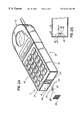
- FIG. 1 illustrates a prior art implementation of a microphone placed in a handset terminal
- FIG. 2 a shows an exploded perspective view of a handset with the embedded microphone according to the present invention
- FIG. 2 b is a sectional view of the transmitting end of a handset with the embedded microphone
- FIG. 3 a is an exploded view of a neckset with the embedded microphone
- FIG. 3 b is a sectional view of the transmitting end of a neckset with the embedded microphone.
- FIG. 4 illustrates the frequency response of the arrangement illustrated in FIGS. 3 a and 3 b for a number of source directions.
- a telephone handset comprises a housing 10 having a transmit end 11 and a receive end 12 .
- a microphone is placed at the transmit end 11 and a receiver is placed at the receive end 12 .
- the transmit end 11 has openings 17 and 18 , each arranged respectively on face 15 and 16 . It is apparent that mounting the microphone as illustrated in FIG. 1, so that one port is on the face plate, and the other is on the end of the terminal, can meet requirement 2 , but does not comply with requirements 1 and 4.
- FIGS. 2 a and 2 b illustrate an implementation for a handset according to this invention, where the microphone 22 is embedded with zero profile into a cavity 23 provided in the end face 16 of housing 10 .
- Cavity 23 should be deep enough so that the microphone capsule 22 is fully received therein, while leaving free space in the cavity around the poles of the microphone. While the depth of the cavity is determined mostly by the diameter of the capsule 22 , the distance between each port and the facing cavity wall is determined by the design restrains of the housing and the acoustic impedance of the microphone assembly, as will be discussed later in further detail. In this way, the microphone is practically in an open space. It is not necessary for any of the microphone ports 24 and 25 to actually be visible from the direction of the sound source.
- the invention is particularly effective with microphones which have a front to back symmetry such as the “FIG. 8 ” pattern, or dipole microphone. Diffraction and reflection of noise impinging on the side of the microphone (the direction of minimum sensitivity) is symmetric and therefore does not hinder the intrinsic noise canceling ability of the microphone. This meets requirement 1 above.
- the large openings to the spaces above and below the microphone serve to meet requirement 3 above.
- Cavity 23 is selected to have a substantially regular shape, for enabling symmetrical positioning of the microphone inside it.
- the walls facing the microphone ports are inclined outwardly, as illustrated in FIGS. 2 a and 2 b .
- the microphone 22 is fixed in the center of the cavity. It is important that the geometrical center of the cavity substantially coincides with the geometrical center of the microphone, for obtaining a high degree of acoustic symmetry (requirement 4) between the front and the back of the microphone.
- Cavity 23 must also allow enough free space around the ports so that the acoustic impedance of the ports is much less than the acoustic impedance of the microphone. If the ports impedance is low, it will only negligibly alter the pressure received at microphone ports 24 and 25 .
- the capsule with microphone 22 is fixed within the cavity 23 with any suitable fixing means.
- the port axis (P) of the capsule 22 should be parallel with the bottom wall of the cavity.
- the geometrical center of the capsule should coincide with the geometrical center of the cavity.
- the capsule may be fixed with a suitable type of glue along dotted line 27 .
- capsule 22 may be fixed into the cavity 23 using tabs positioned along dotted line 28 .
- the electrical signals obtained with the microphone 22 are carried to the electronics of the receiver through wires 20 which are inserted into the housing through holes 21 .
- Cavity 23 is covered with an acoustically transparent screen 26 , which protects the microphone while allowing the sound waves to enter the cavity and arrive at ports 24 and 25 unobstructed.
- the set illustrated in FIG. 1 When the set illustrated in FIG. 1 is used handsfree, it is generally positioned at some 30 cm so that face 15 faces the user. This implementation of the microphone would not only have the most sensitive direction pointed at the user, but can simultaneously point a null of the set's loudspeaker if a dipole microphone is used.
- selection of the acoustic design and the place of the cavity should take into account the type and size of the microphone assembly and the architecture of the housing.
- FIG. 3 a illustrates the implementation for a neckset.
- Such neckset is disclosed and claimed in U.S. application Ser. No. 08/611,961, filed Mar. 7, 1996, which is a Continuation-In-Part of U.S. application Ser. No. 08/257,254, filed Jun. 8, 1994, now abandoned.
- the microphone is sufficiently far from the user that some noise cancellation is appropriate.
- the microphone is embedded into the front face 15 of the housing 30 , with zero profile, and is covered with a screen 32 .
- the capsule with microphone 22 is fixed within the cavity 31 with any suitable fixing means.
- the capsule median transversal plane should coincide with the median plane of cavity 31 .
- the capsule may be fixed with a suitable glue along dotted line 33 .
- capsule 22 may be fixed into the cavity 31 using tabs positioned along dotted line 33 .
- the capsule may be fixed inside the cavity using a narrow wall extending as a bridge across the opening, for additionally supporting the capsule between the bridge and the bottom wall of the cavity.
- cavity 31 is larger than in the case of the handset, and a lower acoustic impedance is obtained.
- the quality of the sound is advantageously enhanced by the fact that the body of the wearer obstructs the noise coming from the side opposed to the opening of the cavity.
- FIG. 4 shows that the sensitivity in the direction of the user is significantly better than at 45 degrees away, and markedly better still than at 90 degrees away (in the direction of computers, keyboards, other talkers, etc.).
Abstract
Description
Claims (15)
Priority Applications (7)
| Application Number | Priority Date | Filing Date | Title |
|---|---|---|---|
| US08/535,404 US6421444B1 (en) | 1995-09-28 | 1995-09-28 | Embedded higher order microphone |
| JP9513018A JPH10512419A (en) | 1995-09-28 | 1996-01-10 | Embedded high-order microphone |
| AU43257/96A AU701640B2 (en) | 1995-09-28 | 1996-01-10 | Embedded higher order microphone |
| DE69613706T DE69613706T2 (en) | 1995-09-28 | 1996-01-10 | MOUNTING ARRANGEMENT OF A NOISE-CANCELING MICROPHONE |
| CA002228657A CA2228657C (en) | 1995-09-28 | 1996-01-10 | Mounting arrangement for a noise cancelling microphone |
| PCT/CA1996/000011 WO1997012495A1 (en) | 1995-09-28 | 1996-01-10 | Mounting arrangement for a noise cancelling microphone |
| EP96900070A EP0852891B1 (en) | 1995-09-28 | 1996-01-10 | Mounting arrangement for a noise cancelling microphone |
Applications Claiming Priority (1)
| Application Number | Priority Date | Filing Date | Title |
|---|---|---|---|
| US08/535,404 US6421444B1 (en) | 1995-09-28 | 1995-09-28 | Embedded higher order microphone |
Publications (1)
| Publication Number | Publication Date |
|---|---|
| US6421444B1 true US6421444B1 (en) | 2002-07-16 |
Family
ID=24134036
Family Applications (1)
| Application Number | Title | Priority Date | Filing Date |
|---|---|---|---|
| US08/535,404 Expired - Lifetime US6421444B1 (en) | 1995-09-28 | 1995-09-28 | Embedded higher order microphone |
Country Status (7)
| Country | Link |
|---|---|
| US (1) | US6421444B1 (en) |
| EP (1) | EP0852891B1 (en) |
| JP (1) | JPH10512419A (en) |
| AU (1) | AU701640B2 (en) |
| CA (1) | CA2228657C (en) |
| DE (1) | DE69613706T2 (en) |
| WO (1) | WO1997012495A1 (en) |
Cited By (7)
| Publication number | Priority date | Publication date | Assignee | Title |
|---|---|---|---|---|
| US20030083116A1 (en) * | 2001-10-30 | 2003-05-01 | Temco Japan Co., Ltd. | Handset for a communication unit |
| US20040114753A1 (en) * | 2002-12-13 | 2004-06-17 | Xiaozhou Wang | Cover assembly of mobile phone |
| US20050069164A1 (en) * | 2003-09-30 | 2005-03-31 | Sivakumar Muthuswamy | Microphone system for a communication device |
| US20100100209A1 (en) * | 2008-10-17 | 2010-04-22 | Sanyo Electric Co., Ltd. | Sound-recording apparatus |
| US20100128914A1 (en) * | 2008-11-26 | 2010-05-27 | Analog Devices, Inc. | Side-ported MEMS microphone assembly |
| US9226052B2 (en) | 2013-01-22 | 2015-12-29 | Invensense, Inc. | Microphone system with non-orthogonally mounted microphone die |
| US9628596B1 (en) | 2016-09-09 | 2017-04-18 | Sorenson Ip Holdings, Llc | Electronic device including a directional microphone |
Families Citing this family (2)
| Publication number | Priority date | Publication date | Assignee | Title |
|---|---|---|---|---|
| WO1999002010A1 (en) * | 1997-07-04 | 1999-01-14 | Maxon Systems Inc. (London) Ltd. | Enclosure for a microphone |
| DE19953203A1 (en) | 1999-11-05 | 2007-12-06 | Basf Coatings Ag | Process for the preparation of multicoat color and / or effect paint systems using self-crosslinking graft copolymers of polyurethanes and novel self-crosslinking polyurethanes and their graft copolymers |
Citations (12)
| Publication number | Priority date | Publication date | Assignee | Title |
|---|---|---|---|---|
| US4420657A (en) * | 1981-10-29 | 1983-12-13 | Acs Communications, Inc. | Adjustable headset |
| US4528426A (en) * | 1983-11-23 | 1985-07-09 | Northern Telecom Limited | Directional microphone assembly |
| CA1199138A (en) | 1983-11-29 | 1986-01-07 | Peter Fatovic | Telephone handset having close-talking microphone |
| US4742548A (en) | 1984-12-20 | 1988-05-03 | American Telephone And Telegraph Company | Unidirectional second order gradient microphone |
| EP0330364A2 (en) | 1988-02-26 | 1989-08-30 | Nortel Networks Corporation | Modular microphone assembly |
| DE3907895A1 (en) | 1988-04-20 | 1989-11-02 | Primo Co Ltd | Directional microphone |
| US5121426A (en) | 1989-12-22 | 1992-06-09 | At&T Bell Laboratories | Loudspeaking telephone station including directional microphone |
| EP0493361A2 (en) | 1990-12-27 | 1992-07-01 | AKG Akustische u. Kino-Geräte Gesellschaft m.b.H. | Telephone-handset fitted with a directional microphone |
| US5168525A (en) * | 1989-08-16 | 1992-12-01 | Georg Neumann Gmbh | Boundary-layer microphone |
| WO1992022176A1 (en) | 1991-05-28 | 1992-12-10 | Motorola, Inc. | Noise cancelling microphone and boot mounting arrangement |
| US5226076A (en) * | 1993-02-28 | 1993-07-06 | At&T Bell Laboratories | Directional microphone assembly |
| US5239578A (en) | 1990-05-15 | 1993-08-24 | Plantronics, Inc. | Noise cancelling apparatus for a telephone handset |
-
1995
- 1995-09-28 US US08/535,404 patent/US6421444B1/en not_active Expired - Lifetime
-
1996
- 1996-01-10 CA CA002228657A patent/CA2228657C/en not_active Expired - Fee Related
- 1996-01-10 JP JP9513018A patent/JPH10512419A/en active Pending
- 1996-01-10 DE DE69613706T patent/DE69613706T2/en not_active Expired - Lifetime
- 1996-01-10 AU AU43257/96A patent/AU701640B2/en not_active Ceased
- 1996-01-10 EP EP96900070A patent/EP0852891B1/en not_active Expired - Lifetime
- 1996-01-10 WO PCT/CA1996/000011 patent/WO1997012495A1/en active IP Right Grant
Patent Citations (13)
| Publication number | Priority date | Publication date | Assignee | Title |
|---|---|---|---|---|
| US4420657A (en) * | 1981-10-29 | 1983-12-13 | Acs Communications, Inc. | Adjustable headset |
| US4420657B1 (en) * | 1981-10-29 | 1988-04-26 | ||
| US4528426A (en) * | 1983-11-23 | 1985-07-09 | Northern Telecom Limited | Directional microphone assembly |
| CA1199138A (en) | 1983-11-29 | 1986-01-07 | Peter Fatovic | Telephone handset having close-talking microphone |
| US4742548A (en) | 1984-12-20 | 1988-05-03 | American Telephone And Telegraph Company | Unidirectional second order gradient microphone |
| EP0330364A2 (en) | 1988-02-26 | 1989-08-30 | Nortel Networks Corporation | Modular microphone assembly |
| DE3907895A1 (en) | 1988-04-20 | 1989-11-02 | Primo Co Ltd | Directional microphone |
| US5168525A (en) * | 1989-08-16 | 1992-12-01 | Georg Neumann Gmbh | Boundary-layer microphone |
| US5121426A (en) | 1989-12-22 | 1992-06-09 | At&T Bell Laboratories | Loudspeaking telephone station including directional microphone |
| US5239578A (en) | 1990-05-15 | 1993-08-24 | Plantronics, Inc. | Noise cancelling apparatus for a telephone handset |
| EP0493361A2 (en) | 1990-12-27 | 1992-07-01 | AKG Akustische u. Kino-Geräte Gesellschaft m.b.H. | Telephone-handset fitted with a directional microphone |
| WO1992022176A1 (en) | 1991-05-28 | 1992-12-10 | Motorola, Inc. | Noise cancelling microphone and boot mounting arrangement |
| US5226076A (en) * | 1993-02-28 | 1993-07-06 | At&T Bell Laboratories | Directional microphone assembly |
Cited By (12)
| Publication number | Priority date | Publication date | Assignee | Title |
|---|---|---|---|---|
| US20030083116A1 (en) * | 2001-10-30 | 2003-05-01 | Temco Japan Co., Ltd. | Handset for a communication unit |
| US7162280B2 (en) * | 2001-10-30 | 2007-01-09 | Temco Japan Co., Ltd. | Handset for a communication unit |
| US20040114753A1 (en) * | 2002-12-13 | 2004-06-17 | Xiaozhou Wang | Cover assembly of mobile phone |
| US20050069164A1 (en) * | 2003-09-30 | 2005-03-31 | Sivakumar Muthuswamy | Microphone system for a communication device |
| US7233679B2 (en) | 2003-09-30 | 2007-06-19 | Motorola, Inc. | Microphone system for a communication device |
| US20100100209A1 (en) * | 2008-10-17 | 2010-04-22 | Sanyo Electric Co., Ltd. | Sound-recording apparatus |
| US8295959B2 (en) * | 2008-10-17 | 2012-10-23 | Sanyo Electric Co., Ltd. | Sound-recording apparatus |
| US20100128914A1 (en) * | 2008-11-26 | 2010-05-27 | Analog Devices, Inc. | Side-ported MEMS microphone assembly |
| US8351634B2 (en) * | 2008-11-26 | 2013-01-08 | Analog Devices, Inc. | Side-ported MEMS microphone assembly |
| US9226052B2 (en) | 2013-01-22 | 2015-12-29 | Invensense, Inc. | Microphone system with non-orthogonally mounted microphone die |
| US9628596B1 (en) | 2016-09-09 | 2017-04-18 | Sorenson Ip Holdings, Llc | Electronic device including a directional microphone |
| US10623544B1 (en) | 2016-09-09 | 2020-04-14 | Sorenson Ip Holdings, Llc | Electronic device including a directional microphone |
Also Published As
| Publication number | Publication date |
|---|---|
| AU701640B2 (en) | 1999-02-04 |
| EP0852891B1 (en) | 2001-07-04 |
| AU4325796A (en) | 1997-04-17 |
| DE69613706T2 (en) | 2002-05-08 |
| EP0852891A1 (en) | 1998-07-15 |
| DE69613706D1 (en) | 2001-08-09 |
| CA2228657C (en) | 2004-01-06 |
| JPH10512419A (en) | 1998-11-24 |
| CA2228657A1 (en) | 1997-04-03 |
| WO1997012495A1 (en) | 1997-04-03 |
Similar Documents
| Publication | Publication Date | Title |
|---|---|---|
| US6633647B1 (en) | Method of custom designing directional responses for a microphone of a portable computer | |
| US8428285B2 (en) | Microphone screen with common mode interference reduction | |
| US7162041B2 (en) | Noise canceling microphone with acoustically tuned ports | |
| EP0985327B1 (en) | Flush mounted uni-directional microphone | |
| JP2609822B2 (en) | Transmitter | |
| US4528426A (en) | Directional microphone assembly | |
| US20110176698A1 (en) | Differential Microphone | |
| MXPA05004307A (en) | Electronic device having a multi-mode acoustic system and method for radiating sound waves. | |
| US4885773A (en) | Apparatus for mounting a unidirectional microphone in a hands-free telephone subset | |
| JP2000032584A (en) | Unidirectional microphone | |
| US5651074A (en) | Noise canceling gradient microphone assembly | |
| JP2009135777A (en) | Microphone unit and voice input device | |
| US6421444B1 (en) | Embedded higher order microphone | |
| US8135144B2 (en) | Microphone system, sound input apparatus and method for manufacturing the same | |
| EP0637187B1 (en) | Two-way communications earset | |
| US6275580B1 (en) | Teleconferencing device having acoustic transducers positioned to improve acoustic echo return loss | |
| JPS62110349A (en) | Transmitter | |
| CN110868669A (en) | Directional microphone | |
| US10448135B2 (en) | Directional microphone integrated into device case | |
| CN112019984A (en) | Electronic device | |
| JP3567703B2 (en) | Earset handset | |
| CN216356802U (en) | Mobile terminal equipment | |
| JPH03117148A (en) | Loudspeaker telephone set | |
| JPS62203453A (en) | Noise preventing type transmitter | |
| JPH04281649A (en) | Talking device |
Legal Events
| Date | Code | Title | Description |
|---|---|---|---|
| AS | Assignment |
Owner name: BELL-NORTHERN RESEARCH, LTD., CANADA Free format text: ASSIGNMENT OF ASSIGNORS INTEREST;ASSIGNOR:VAN SCHYNDEL, ANDRE JOHN;REEL/FRAME:007957/0816 Effective date: 19950920 |
|
| AS | Assignment |
Owner name: NORTHERN TELECOM LIMITED, CANADA Free format text: ASSIGNMENT OF ASSIGNORS INTEREST;ASSIGNOR:BELL-NORTHERN RESEARCH LTD.;REEL/FRAME:007907/0012 Effective date: 19951214 |
|
| AS | Assignment |
Owner name: NORTEL NETWORKS CORPORATION, CANADA Free format text: CHANGE OF NAME;ASSIGNOR:NORTHERN TELECOM LIMITED;REEL/FRAME:010567/0001 Effective date: 19990429 |
|
| AS | Assignment |
Owner name: NORTEL NETWORKS LIMITED, CANADA Free format text: CHANGE OF NAME;ASSIGNOR:NORTEL NETWORKS CORPORATION;REEL/FRAME:011195/0706 Effective date: 20000830 Owner name: NORTEL NETWORKS LIMITED,CANADA Free format text: CHANGE OF NAME;ASSIGNOR:NORTEL NETWORKS CORPORATION;REEL/FRAME:011195/0706 Effective date: 20000830 |
|
| STCF | Information on status: patent grant |
Free format text: PATENTED CASE |
|
| FPAY | Fee payment |
Year of fee payment: 4 |
|
| FPAY | Fee payment |
Year of fee payment: 8 |
|
| AS | Assignment |
Owner name: ROCKSTAR BIDCO, LP, NEW YORK Free format text: ASSIGNMENT OF ASSIGNORS INTEREST;ASSIGNOR:NORTEL NETWORKS LIMITED;REEL/FRAME:027164/0356 Effective date: 20110729 |
|
| FPAY | Fee payment |
Year of fee payment: 12 |
|
| AS | Assignment |
Owner name: ROCKSTAR CONSORTIUM US LP, TEXAS Free format text: ASSIGNMENT OF ASSIGNORS INTEREST;ASSIGNOR:ROCKSTAR BIDCO, LP;REEL/FRAME:032388/0467 Effective date: 20120509 |
|
| AS | Assignment |
Owner name: RPX CLEARINGHOUSE LLC, CALIFORNIA Free format text: ASSIGNMENT OF ASSIGNORS INTEREST;ASSIGNORS:ROCKSTAR CONSORTIUM US LP;ROCKSTAR CONSORTIUM LLC;BOCKSTAR TECHNOLOGIES LLC;AND OTHERS;REEL/FRAME:034924/0779 Effective date: 20150128 |