US6416144B1 - Sterilizer horizontal motorized sliding door closure - Google Patents
Sterilizer horizontal motorized sliding door closure Download PDFInfo
- Publication number
- US6416144B1 US6416144B1 US09/540,662 US54066200A US6416144B1 US 6416144 B1 US6416144 B1 US 6416144B1 US 54066200 A US54066200 A US 54066200A US 6416144 B1 US6416144 B1 US 6416144B1
- Authority
- US
- United States
- Prior art keywords
- door
- opening
- chamber
- support member
- housing
- Prior art date
- Legal status (The legal status is an assumption and is not a legal conclusion. Google has not performed a legal analysis and makes no representation as to the accuracy of the status listed.)
- Expired - Fee Related
Links
Images


Classifications
-
- A—HUMAN NECESSITIES
- A61—MEDICAL OR VETERINARY SCIENCE; HYGIENE
- A61L—METHODS OR APPARATUS FOR STERILISING MATERIALS OR OBJECTS IN GENERAL; DISINFECTION, STERILISATION OR DEODORISATION OF AIR; CHEMICAL ASPECTS OF BANDAGES, DRESSINGS, ABSORBENT PADS OR SURGICAL ARTICLES; MATERIALS FOR BANDAGES, DRESSINGS, ABSORBENT PADS OR SURGICAL ARTICLES
- A61L2/00—Disinfection or sterilisation of materials or objects, in general; Accessories therefor
- A61L2/26—Accessories
-
- A—HUMAN NECESSITIES
- A61—MEDICAL OR VETERINARY SCIENCE; HYGIENE
- A61L—METHODS OR APPARATUS FOR STERILISING MATERIALS OR OBJECTS IN GENERAL; DISINFECTION, STERILISATION OR DEODORISATION OF AIR; CHEMICAL ASPECTS OF BANDAGES, DRESSINGS, ABSORBENT PADS OR SURGICAL ARTICLES; MATERIALS FOR BANDAGES, DRESSINGS, ABSORBENT PADS OR SURGICAL ARTICLES
- A61L2202/00—Aspects relating to methods or apparatus for disinfecting or sterilising materials or objects
- A61L2202/10—Apparatus features
- A61L2202/12—Apparatus for isolating biocidal substances from the environment
- A61L2202/121—Sealings, e.g. doors, covers, valves, sluices
-
- E—FIXED CONSTRUCTIONS
- E05—LOCKS; KEYS; WINDOW OR DOOR FITTINGS; SAFES
- E05F—DEVICES FOR MOVING WINGS INTO OPEN OR CLOSED POSITION; CHECKS FOR WINGS; WING FITTINGS NOT OTHERWISE PROVIDED FOR, CONCERNED WITH THE FUNCTIONING OF THE WING
- E05F15/00—Power-operated mechanisms for wings
- E05F15/60—Power-operated mechanisms for wings using electrical actuators
- E05F15/603—Power-operated mechanisms for wings using electrical actuators using rotary electromotors
- E05F15/632—Power-operated mechanisms for wings using electrical actuators using rotary electromotors for horizontally-sliding wings
- E05F15/643—Power-operated mechanisms for wings using electrical actuators using rotary electromotors for horizontally-sliding wings operated by flexible elongated pulling elements, e.g. belts, chains or cables
- E05F15/646—Power-operated mechanisms for wings using electrical actuators using rotary electromotors for horizontally-sliding wings operated by flexible elongated pulling elements, e.g. belts, chains or cables allowing or involving a secondary movement of the wing, e.g. rotational or transversal
-
- E—FIXED CONSTRUCTIONS
- E05—LOCKS; KEYS; WINDOW OR DOOR FITTINGS; SAFES
- E05Y—INDEXING SCHEME ASSOCIATED WITH SUBCLASSES E05D AND E05F, RELATING TO CONSTRUCTION ELEMENTS, ELECTRIC CONTROL, POWER SUPPLY, POWER SIGNAL OR TRANSMISSION, USER INTERFACES, MOUNTING OR COUPLING, DETAILS, ACCESSORIES, AUXILIARY OPERATIONS NOT OTHERWISE PROVIDED FOR, APPLICATION THEREOF
- E05Y2201/00—Constructional elements; Accessories therefor
- E05Y2201/20—Brakes; Disengaging means; Holders; Stops; Valves; Accessories therefor
- E05Y2201/218—Holders
- E05Y2201/22—Locks
-
- E—FIXED CONSTRUCTIONS
- E05—LOCKS; KEYS; WINDOW OR DOOR FITTINGS; SAFES
- E05Y—INDEXING SCHEME ASSOCIATED WITH SUBCLASSES E05D AND E05F, RELATING TO CONSTRUCTION ELEMENTS, ELECTRIC CONTROL, POWER SUPPLY, POWER SIGNAL OR TRANSMISSION, USER INTERFACES, MOUNTING OR COUPLING, DETAILS, ACCESSORIES, AUXILIARY OPERATIONS NOT OTHERWISE PROVIDED FOR, APPLICATION THEREOF
- E05Y2201/00—Constructional elements; Accessories therefor
- E05Y2201/20—Brakes; Disengaging means; Holders; Stops; Valves; Accessories therefor
- E05Y2201/23—Actuation thereof
- E05Y2201/232—Actuation thereof by automatically acting means
- E05Y2201/236—Actuation thereof by automatically acting means using force or torque
-
- E—FIXED CONSTRUCTIONS
- E05—LOCKS; KEYS; WINDOW OR DOOR FITTINGS; SAFES
- E05Y—INDEXING SCHEME ASSOCIATED WITH SUBCLASSES E05D AND E05F, RELATING TO CONSTRUCTION ELEMENTS, ELECTRIC CONTROL, POWER SUPPLY, POWER SIGNAL OR TRANSMISSION, USER INTERFACES, MOUNTING OR COUPLING, DETAILS, ACCESSORIES, AUXILIARY OPERATIONS NOT OTHERWISE PROVIDED FOR, APPLICATION THEREOF
- E05Y2999/00—Subject-matter not otherwise provided for in this subclass
Definitions
- the present invention relates to the door closure arts. It finds particular application in conjunction with a horizontal sliding door for sealing the opening to a sterilization chamber and will be described with particular reference thereto. It should be appreciated, however, that the invention is also applicable to a wide variety of other closure systems.
- the guidance system commonly includes a combination of rollers and recessed tracks.
- Unique bracketing is often needed to mount the rollers and unique tracks are generally provided which have the sole purpose of guidance. Additionally, because of the recesses, the guidance system does not provide guidance, and thus seal protection, for the entire door translation.
- U.S. pat. No. 6,017,105 to Goughnour, et al. provides a sliding door guidance method for a walk-in sterilizer in which recesses in guidance tracks above and below the door receive guidance rollers at the top and bottom of the door when the door is in the closed position.
- the rollers must properly engage the recesses, otherwise pressure on the rollers when the door translates could cause damage to the rollers and associated hardware.
- the present invention provides for a new and improved guidance method for a horizontal sliding door which overcomes the above-referenced problems and others.
- a sterilization or disinfection apparatus in accordance with one aspect of the present invention, includes a housing which defines an interior chamber and an opening.
- a door has an interior face sized to seal the opening and an outer face.
- a horizontal support rail is mounted to the housing.
- a guidance assembly guides the door between an open position, in which items to be sterilized or disinfected are capable of being loaded into the chamber, and a closed position, in which the door covers the opening.
- the guidance assembly includes a pivotable support member, pivotally connected with the door. The pivotable support member is carried by the rail during opening and closing of the door.
- a method of guiding a sliding door between an open position, in which access is provided to the interior of a steam cabinet through an opening defined in the cabinet, and a closed position, in which the opening is covered by the door includes suspending the door from a pivotable support member which is pivotally connected with the door and rolling a roller which is rotatably connected to the pivotable support member along a horizontal track mounted adjacent the opening.
- Another advantage of the present invention is that the guidance system provides axial translation for pressure load reversals within the sterilizer.
- Another advantage of the present invention is that the door locks automatically, in response to pressure changes within the chamber.
- Another advantage of the present invention is that the motor drive cable and pulley door actuation system eliminates the need for a door obstruction sensor, thereby simplifying the design and providing an inherently safe system.
- the invention may take form in various components and arrangement of components and in various steps and arrangements of steps.
- the drawings are only for purposes of illustrating a preferred embodiment and are not to be construed as limiting the invention.
- FIG. 1 is a front perspective view of a steam sterilizer with a horizontal sliding door, in accordance with the present invention
- FIG. 2 is a perspective view of the sterilizer of FIG. 1, with the door in an open position;
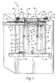
- FIG. 4 is a side view of the sterilizer of FIG. 1;
- FIG. 5 is a side view of the door of FIG. 1;
- FIG. 6 is a perspective view of the door of FIG. 1;
- FIG. 8 is an enlarged perspective view of the lower spring roller of FIG. 1;
- FIG. 9 is a side view of the forward end of the sterilize of FIG. 1;
- a steam decontamination apparatus for sterilizing or disinfecting items includes a cabinet 10 which defines an interior chamber 12 .
- the term “decontamination” and similar terms encompass sterilization, disinfection, and other forms of antimicrobial treatment.
- a horizontal sliding door assembly 20 includes a horizontal sliding door 22 , a support system 24 mounted to the front wall of the cabinet for supporting the weight of the door during translation and limiting outward movement of the door, and a guidance assembly 28 , carried by the door, which allows in and out movement of the door 22 in a direction perpendicular to the end frame 18 of the sterilizer.
- the door includes two vertically extending structural channels 42 and 44 , which are mounted to a front face 46 of the pressure plate 40 , adjacent left and right vertical sides 47 , 48 of the plate, respectively.
- the channels are welded or otherwise rigidly attached to the pressure plate.
- the structural channels buttress the left and right vertical sides 47 , 48 of the pressure plate (i.e., the trailing edge and leading edge of the door, respectively) against flexing outward or inward under the pressures experienced during sterilization, and thus preferably extend close to the full length of the pressure plate.
- the structural channels 42 , 44 are box-shaped and define an internal cavity 50 , 52 , respectively.
- a cosmetic cover covers the front of the door, screening the pressure plate 40 and structural channels 42 , 44 from view.
- the support system 24 includes upper and lower horizontally extending L-shaped restraining members 60 , 62 which are mounted to the end frame of the sterilizer above and below the opening 16 , respectively, and receive upper and lower horizontal sides 66 , 68 of the pressure plate, respectively.
- a seal 70 extends around the periphery of the opening 16 in the end frame 18 of the cabinet for sealingly engaging an interior face 72 of the pressure plate when the door is in the closed position.
- the seal 70 is an active seal, such as a gasket which is mounted in a groove 74 on the end frame or other exterior surface of the cabinet, best shown in FIG. 4 .
- the seal 70 When the seal 70 is activated, such as by pressurizing the gasket with steam, the gasket extends outwardly and the door plate 40 is pushed outwardly toward vertically extending forward portions 76 , 78 of the L-shaped restraining members 60 , 62 , respectively.
- the restraining members 60 , 62 thus limit outward movement of the door during a sterilization cycle and buttress the top 66 and bottom 68 of the door against flexing.
- the door is thus buttressed adjacent all four sides 47 , 48 , 66 , 68 of the pressure plate during the pressure phases of a sterilization cycle.
- the door moves outward slightly, until met by the resistance provided by the forward portions 76 , 78 of the restraining members.
- the seal 70 is configured for maintaining sealing contact with the pressure plate 40 during this outward movement.
- the pressure within the chamber 12 is reduced below atmospheric pressure, the door moves inward, toward the end frame 18 .
- the guidance assembly 28 includes two pivotable supports 90 , 92 , which mount the door to the support rail 80 .
- a left pivotable support 90 is pivotally connected to the left structural channel 42 and the right pivotable support 92 is pivotally connected to the right structural channel.
- three or more structural channels and corresponding pivotable supports may be used for large sized doors, or that only a single pivotable support be used. However, for conventional sterilizer sizes, two pivotable supports are sufficient to carry the weight of the door 22 .
- Each pivotable support 90 , 92 includes a vertically extending rod or bar 94 , 96 , respectively.
- a lower end 97 , 98 of each bar, respectively, is received within the cavity 50 , 52 of the corresponding structural channel.
- Each lower end 97 , 98 has a suitably positioned bore 100 formed therein which receives a horizontal pivot pin 102 , 104 therethrough.
- the pivot pins are supported at either end by side portions 106 , 108 of each of the structural channels 42 , 44 , respectively. In this way, the pivotable supports 90 , 92 are pivotally connected via the lower end of each bar to the corresponding bracket.
- the door 22 is able to pivot about the pivot pins 102 , 104 .
- the pivotable supports 90 , 92 independently pivot on their respective structural channels 42 , 44 , thereby removing stresses which would otherwise develop in a rigidly connected support.
- the pivotable support pivots about the pivot point in the direction P (see FIG. 5 ).
- the pivotable support pivots in the direction P′.
- a door positioning system 130 such as a system of spring-biased rollers, or other door positioners, provide the reacting forces represented by arrows A and B in FIG. 5, which maintain the door 22 in a generally vertical position.
- the door positioning system allows the door to move between open and closed positions without contacting the end frame 18 and seal 70 or the restraining bars 60 , 62 .
- the door positioning system also permits the door to move in and out under the influence of changing pressure within the chamber and contact the end frame 18 or restraining bars 60 , 62 .
- the forces applied by the spring rollers are relatively small.
- the upper door positioners 132 , 134 each include a resiliently flexible U-shaped plate 142 or other biasing element, such as a spring.
- the biasing element is preferably preloaded. By preloaded, it is meant that the positioner is already under tension, so that a small additional deflection results in the generation of a significant resistive force.
- the right hand door positioner 134 is shown. It will be appreciated that the left hand door positioner 132 is a mirror image of the right hand door positioner.
- a flange 144 on an outer arm 146 of the U-shaped plate is mounted to the respective structural channel flange 138 , 140 , with screws, bolts, or other convenient attachment members.
- An inner arm 148 of the U-shaped plate 142 carries a vertically extending pin 150 at an outer end thereof on which a roller 152 is rotatably mounted.
- the roller 152 rollingly engages an upper guide surface, such as a forward outer surface 154 of forward portion 76 of the upper restraining member 60 , as the door translates.
- the U-shaped plate 142 is resiliently flexible so that the door 22 is able to move in and out by a small amount under the changing pressure within the sterilizer.
- the U-shaped plates of the upper door positioners are placed under stress (i.e., the width w between the inner and outer arms 148 , 146 of the plate is reduced, creating tension in the plate).
- the stress assists in returning the door to its original position when the pressure in the chamber is returned to atmospheric pressure and the stress is relieved.
- the door positioners 132 , 134 function independently, such that one U-shaped plate may be placed under greater or lesser stress at any one time. While three or more upper door positioners may be used in place of two, this is not necessarily advantageous, since it is likely that only two of the rollers may make contact with the restraining member at any one time.
- the lower door positioner 136 is centrally mounted to the front face 46 of the pressure plate 40 adjacent the lower end 68 of the door.
- the lower door positioner includes a U-shaped plate 160 , which functions similarly to the U-shaped plate of the upper door positioners. In this case, however, the U-shaped plate is vertically, rather than horizontally aligned, with a mounting flange 162 extending from an inner arm 164 of the U-shaped plate.
- An outer arm 166 of the U-shaped plate has an inwardly extending flange 168 at its lower end.
- a vertically extending pin 170 hangs from the flange 168 and carries a roller 172 thereon.
- the roller 172 rollingly engages a lower guide surface, such as a vertical inner surface 174 of an L-shaped roller guide 176 which is mounted forwardly of the lower restraining member 62 (see FIG. 4 ).
- a lower guide surface such as a vertical inner surface 174 of an L-shaped roller guide 176 which is mounted forwardly of the lower restraining member 62 (see FIG. 4 ).
- the door moves outwardly until it engages the restraining members 60 , 62 .
- the U-shaped plate 160 of the lower door positioner is placed under stress during this movement, which helps to return the door to its original position when the pressure excess is removed.
- the upper door positioners 132 , 134 thus bias the top of the door outward in the direction of arrow A, while the lower door positioner 136 biases the door inward in the direction of arrow B, thereby positioning the door vertically, while also allowing in and out movement of the door under the effects of pressure changes within the sterilizer. It should be understood that the term bias is used herein to indicate that the door is being moved to a vertical position, rather than to a skewed position.
- the door positioners 132 , 134 , 136 are positioned such that the rollers make contact with the guide surfaces 154 , 174 , respectively. It is preferable to have only a single door positioner 136 at the bottom center of the door, rather than an additional fourth door positioner. This ensures that each of the door positioners 132 , 134 , 136 is making contact with its respective contact surface 154 , 174 at all times. Spacing members 180 , 182 connect the inner and outer arms of the U-shaped plate to provide the preload.
- Adjustment of the preload (initial tension) on the door positioners is achieved through adjustment of screws 183 which are received through suitably positioned elongated mounting slots 184 , 186 in the mounting flange 182 .
- the screws 183 are adjusted in the slots, as necessary, after the door 22 has been hung in position, to align the door vertically. The adjustment changes the position of the rollers and the force they apply.
- a drive system 190 moves the door 22 between open and closed positions.
- the drive system includes a motor 192 , which drives a cable 194 between two pulleys 196 , 198 .
- the cable 194 is connected to the upper end 118 of each of the pivotable supports 90 , 92 .
- the two pulleys 196 , 198 are mounted to brackets attached to the end frame adjacent an upper wall 202 of the cabinet (or to the top of the motor 192 , in the case of pulley 198 ) to support the cable 194 at either end of the cabinet opening 16 .
- the motor 192 When the motor 192 is actuated, the cable 194 pulls the pivotable supports 90 , 92 , and the support rollers 110 , 112 roll along the rail 80 carrying the door 22 between the open and closed positions.
- the cable tension is preferably such that slippage of the cable or stalling of the motor occurs at a preselected driving force, preferably around 10 to 15 kilograms force, more preferably, no greater than 13.6 kilograms force. If an obstruction is positioned in the path of the door, the motor 192 will stall and/or the cable will slip when the predetermined driving force is achieved. This prevents injury or damage from occurring to the obstruction, and avoids the need for a complex system of sensors to detect the absence of obstructions.
- a door locking mechanism 210 prevents the door from opening during the pressure phase of the sterilizing cycle (i.e., when the pressure within the chamber 12 is above-atmospheric).
- the door locking mechanism is actuated by the pressure within the chamber.
- the locking mechanism includes a bracket or support 212 , which is mounted to the top of the lower restraining bar 62 , adjacent the trailing edge 47 of the door, when the door is in the closed position.
- a lever 216 is pivotally connected to the support 212 at a pivot point 218 .
- a first portion 220 of the lever 216 extends in one direction, from the pivot point, towards the trailing vertical edge 47 , and has a hook 222 at a distal end thereof for engaging the trailing edge of the door when the mechanism is in a locked position.
- a second portion 223 of the lever extends from the pivot point, in the opposite direction and has a projection 224 at a distal end thereof, which faces the outer surface 46 of the pressure plate.
- a set screw 226 mounted on the support, adjacent the first portion 220 of the lever, limits outward movement of the first portion of the lever to avoid hindrance by the protrusion.
- the sterilizing or disinfecting apparatus is operated by first loading items to be decontaminated through the opening 16 into the chamber 12 while the door is in the open position illustrated in FIG. 2 .
- the door is then moved into the closed position by operating the motor-driven cable and pulley door actuation system 190 .
- the support rollers 110 , 112 run along the rail 80 and carry the weight of the door.
- the door is guided at the bottom by the lower door positioner 136 and by the upper door positioners 132 , 134 at the top.
- the door 22 thus slides across the opening, centered between the end frame 18 and the restraining bars, thereby avoiding scraping the front of the end frame or damaging the seal.
- the positioning of the slots of the slotted door positioners are adjusted, as needed during the lifetime of the sterilizer, to maintain this small gap at both top and bottom of the door.
- the cycle may include one or more pressure phases, in which steam is introduced to the chamber through an inlet pipe 240 from a boiler 242 , or other source of steam.
- the steam from the boiler may also be used to heat an insulating jacket 246 , via the same or a separate inlet pipe 243 , and to pressurize the gasket 70 , via a gasket inlet line 248 .
- the decontamination cycle may also include one or more vacuum phases, in which a vacuum is applied to the chamber 12 , such as by operating a vacuum pump 250 , connected with the chamber by a vacuum line 252 .
- the pivotable support rollers 110 , 112 rotate slightly on the rail during the in and out movement of the door in the direction of arrows R and R′ (see FIG. 5 ).
- the U-shaped plates 142 , 160 flex to allow the door 22 to move in and out.
- the lever 216 of the lock mechanism is pivoted into engagement with the trailing edge 47 of the door during the pressure portion of the cycle.
- the drive motor 192 is actuated to drive the cable 194 in an opposite direction to the closing direction, to open the door 22 once more.
- the decontaminated items are then removed from the chamber 12 .
- the sterilizer door 22 can be opened or closed by hand, simply by pushing the door. There is no need for a crank or other mechanical emergency opening system, as with conventional door systems.
- FIGS. 1 and 2 While the door 22 is shown in FIGS. 1 and 2 as closing from left to right, it will be appreciated that the door may be converted to a right-to-left closing door by adjusting the position of the support rail 80 so that it extends to the right of the opening 16 , rather than to the left.
- the locking mechanism 210 is replaced with an analogous (essentially a mirror image) locking mechanism adjacent the right side of the door.
- the door has been described with respect to an overhead pivotable support system, it is also contemplated that the door may be supported from below, by similar pivotable supports to those described above, but which support the weight of the door from below.
- the pivotable support rollers preferably run on a rail positioned below the opening.
- a similar door positioning system to that described above is preferably used to maintain the door in vertical alignment.
Landscapes
- Health & Medical Sciences (AREA)
- Epidemiology (AREA)
- Life Sciences & Earth Sciences (AREA)
- Animal Behavior & Ethology (AREA)
- General Health & Medical Sciences (AREA)
- Public Health (AREA)
- Veterinary Medicine (AREA)
- Apparatus For Disinfection Or Sterilisation (AREA)
- Lubricants (AREA)
Abstract
Description
Claims (22)
Priority Applications (6)
| Application Number | Priority Date | Filing Date | Title |
|---|---|---|---|
| US09/540,662 US6416144B1 (en) | 2000-03-31 | 2000-03-31 | Sterilizer horizontal motorized sliding door closure |
| ES01935756T ES2233639T3 (en) | 2000-03-31 | 2001-03-30 | SLIDING DOOR FOR STERILIZER. |
| AT01935756T ATE283072T1 (en) | 2000-03-31 | 2001-03-30 | SLIDING DOOR FOR STERILIZER |
| DE60107400T DE60107400T2 (en) | 2000-03-31 | 2001-03-30 | SLIDING DOOR FOR STERILIZER |
| PCT/US2001/040410 WO2001074409A1 (en) | 2000-03-31 | 2001-03-30 | Sliding door for sterilizer |
| EP01935756A EP1267951B1 (en) | 2000-03-31 | 2001-03-30 | Sliding door for sterilizer |
Applications Claiming Priority (1)
| Application Number | Priority Date | Filing Date | Title |
|---|---|---|---|
| US09/540,662 US6416144B1 (en) | 2000-03-31 | 2000-03-31 | Sterilizer horizontal motorized sliding door closure |
Publications (1)
| Publication Number | Publication Date |
|---|---|
| US6416144B1 true US6416144B1 (en) | 2002-07-09 |
Family
ID=24156419
Family Applications (1)
| Application Number | Title | Priority Date | Filing Date |
|---|---|---|---|
| US09/540,662 Expired - Fee Related US6416144B1 (en) | 2000-03-31 | 2000-03-31 | Sterilizer horizontal motorized sliding door closure |
Country Status (6)
| Country | Link |
|---|---|
| US (1) | US6416144B1 (en) |
| EP (1) | EP1267951B1 (en) |
| AT (1) | ATE283072T1 (en) |
| DE (1) | DE60107400T2 (en) |
| ES (1) | ES2233639T3 (en) |
| WO (1) | WO2001074409A1 (en) |
Cited By (21)
| Publication number | Priority date | Publication date | Assignee | Title |
|---|---|---|---|---|
| US20030193272A1 (en) * | 2001-11-09 | 2003-10-16 | Bryan John I. | Mail handling safety system |
| US20040093801A1 (en) * | 2002-11-15 | 2004-05-20 | Steris Inc. | Door assembly for sealing a chamber |
| US20050045609A1 (en) * | 2003-08-28 | 2005-03-03 | Lincoln Global, Inc., A Corporation Of The State Of Delaware | Side door assembly |
| WO2005102400A1 (en) * | 2004-04-27 | 2005-11-03 | Getinge Disinfection Ab | Door device for disinfection chamber and the like |
| US20060261715A1 (en) * | 2005-05-19 | 2006-11-23 | Lincoln Global, Inc. | Engine welder cabinet |
| USD598564S1 (en) | 2008-04-30 | 2009-08-18 | Midmark Corporation | Handle for portable sterilizing apparatus |
| USD598565S1 (en) | 2008-04-30 | 2009-08-18 | Midmark Corporation | External condensation tank for a sterilizer |
| USD603053S1 (en) | 2008-04-30 | 2009-10-27 | Midmark Corporation | Portable sterilizing apparatus |
| US20120048657A1 (en) * | 2010-08-27 | 2012-03-01 | Jules Christen | Self-centering elevator cage door suspension |
| US8236253B2 (en) | 2007-04-30 | 2012-08-07 | Midmark Corporation | Portable sterilizing apparatus for surgical and dental instruments |
| US20140137476A1 (en) * | 2011-07-25 | 2014-05-22 | Soon Seok Kim | Apparatus for automatic/semiautomatic door |
| US20180369433A1 (en) * | 2017-06-27 | 2018-12-27 | American Sterilizer Company | Self-adjusting damper based linear alignment system |
| KR102135233B1 (en) * | 2019-08-09 | 2020-07-17 | 메디파트너 주식회사 | Sterilizer and controlling method threof |
| CN113144237A (en) * | 2021-04-30 | 2021-07-23 | 杭州若奇技术有限公司 | Disinfection cabinet |
| US11352236B2 (en) * | 2016-12-21 | 2022-06-07 | Inventio Ag | Elevator car having a movable car door |
| US20220331463A1 (en) * | 2021-04-16 | 2022-10-20 | Oxti Corporation | Expandable disinfecting device |
| CN115243559A (en) * | 2020-03-02 | 2022-10-25 | Cj第一制糖株式会社 | Disinfection module and opening/closing module |
| DE102021119387A1 (en) | 2021-07-27 | 2023-02-02 | Thomas Reinhart | incubator |
| US12168902B1 (en) | 2022-06-07 | 2024-12-17 | Apple Inc. | Window |
| US12168901B1 (en) | 2021-09-23 | 2024-12-17 | Apple Inc. | Panel with pivoting and translational motion |
| US12366101B2 (en) | 2019-06-24 | 2025-07-22 | De Lama S.P.A. | Magnetically operated closing device for controlled contamination equipment |
Families Citing this family (4)
| Publication number | Priority date | Publication date | Assignee | Title |
|---|---|---|---|---|
| FR3118762B1 (en) * | 2021-01-13 | 2023-05-12 | Groupe H Labbe | DEVICE FOR OPENING/CLOSING AN AUTOCLAVE |
| DE202021102136U1 (en) * | 2021-04-21 | 2021-05-05 | Ermis Medizintechnik E.K. | Handle for a sterilization container |
| CN115045592B (en) * | 2022-06-07 | 2024-05-14 | 成都蓝峰科技有限公司 | Cabin door for hydrogen peroxide low-temperature plasma sterilizer |
| TWM644838U (en) * | 2023-03-02 | 2023-08-11 | 億泰興業有限公司 | Electric door drive mechanism for mechanical equipment |
Citations (11)
| Publication number | Priority date | Publication date | Assignee | Title |
|---|---|---|---|---|
| US1920855A (en) * | 1932-05-20 | 1933-08-01 | Gloekler John Edward | Sliding door cabinet |
| CH604728A5 (en) | 1974-12-16 | 1978-09-15 | Schaerer Ag M | Locking arrangement for sliding door of steriliser |
| WO1983001740A1 (en) | 1981-11-19 | 1983-05-26 | Electrolux Ab | Autoclave door |
| US4651469A (en) * | 1984-07-18 | 1987-03-24 | Genaplast Pte. Ltd. | Sliding door mechanism |
| US5076018A (en) * | 1989-03-23 | 1991-12-31 | Cinetto F.Lli S.R.L. | Device for easily assembling and disassembling slidable doors to and from pieces of furniture |
| US5195790A (en) | 1992-04-15 | 1993-03-23 | American Sterilizer Company | Apparatus for blocking the movement of a chamber door |
| US5237777A (en) | 1992-03-10 | 1993-08-24 | American Sterilizer Company | Apparatus for eliminating slack in motorized cables |
| US5239781A (en) | 1992-04-01 | 1993-08-31 | American Sterilizer Company | Reinforced closure for a pressure vessel |
| US5249392A (en) | 1992-04-01 | 1993-10-05 | American Sterilizer Company | Apparatus for opening and closing a chamber door |
| US5461829A (en) * | 1994-08-29 | 1995-10-31 | Kason Industries, Inc. | Trolley rail system for sliding door |
| US6017105A (en) | 1998-11-03 | 2000-01-25 | Steris Corporation | Horizontal sliding door guidance method |
-
2000
- 2000-03-31 US US09/540,662 patent/US6416144B1/en not_active Expired - Fee Related
-
2001
- 2001-03-30 DE DE60107400T patent/DE60107400T2/en not_active Expired - Lifetime
- 2001-03-30 AT AT01935756T patent/ATE283072T1/en not_active IP Right Cessation
- 2001-03-30 EP EP01935756A patent/EP1267951B1/en not_active Expired - Lifetime
- 2001-03-30 WO PCT/US2001/040410 patent/WO2001074409A1/en not_active Ceased
- 2001-03-30 ES ES01935756T patent/ES2233639T3/en not_active Expired - Lifetime
Patent Citations (11)
| Publication number | Priority date | Publication date | Assignee | Title |
|---|---|---|---|---|
| US1920855A (en) * | 1932-05-20 | 1933-08-01 | Gloekler John Edward | Sliding door cabinet |
| CH604728A5 (en) | 1974-12-16 | 1978-09-15 | Schaerer Ag M | Locking arrangement for sliding door of steriliser |
| WO1983001740A1 (en) | 1981-11-19 | 1983-05-26 | Electrolux Ab | Autoclave door |
| US4651469A (en) * | 1984-07-18 | 1987-03-24 | Genaplast Pte. Ltd. | Sliding door mechanism |
| US5076018A (en) * | 1989-03-23 | 1991-12-31 | Cinetto F.Lli S.R.L. | Device for easily assembling and disassembling slidable doors to and from pieces of furniture |
| US5237777A (en) | 1992-03-10 | 1993-08-24 | American Sterilizer Company | Apparatus for eliminating slack in motorized cables |
| US5239781A (en) | 1992-04-01 | 1993-08-31 | American Sterilizer Company | Reinforced closure for a pressure vessel |
| US5249392A (en) | 1992-04-01 | 1993-10-05 | American Sterilizer Company | Apparatus for opening and closing a chamber door |
| US5195790A (en) | 1992-04-15 | 1993-03-23 | American Sterilizer Company | Apparatus for blocking the movement of a chamber door |
| US5461829A (en) * | 1994-08-29 | 1995-10-31 | Kason Industries, Inc. | Trolley rail system for sliding door |
| US6017105A (en) | 1998-11-03 | 2000-01-25 | Steris Corporation | Horizontal sliding door guidance method |
Cited By (32)
| Publication number | Priority date | Publication date | Assignee | Title |
|---|---|---|---|---|
| US20030193272A1 (en) * | 2001-11-09 | 2003-10-16 | Bryan John I. | Mail handling safety system |
| US20040093801A1 (en) * | 2002-11-15 | 2004-05-20 | Steris Inc. | Door assembly for sealing a chamber |
| US7121042B2 (en) | 2002-11-15 | 2006-10-17 | Steris Inc. | Door assembly for sealing a chamber |
| US20050045609A1 (en) * | 2003-08-28 | 2005-03-03 | Lincoln Global, Inc., A Corporation Of The State Of Delaware | Side door assembly |
| US6969825B2 (en) * | 2003-08-28 | 2005-11-29 | Lincoln Global, Inc. | Side door assembly |
| CN100479864C (en) * | 2004-04-27 | 2009-04-22 | 盖廷格消毒股份公司 | Door device for disinfection chambers and the like |
| WO2005102400A1 (en) * | 2004-04-27 | 2005-11-03 | Getinge Disinfection Ab | Door device for disinfection chamber and the like |
| US20070292324A1 (en) * | 2004-04-27 | 2007-12-20 | Christer Jonsson | Door Device for Disinfection Chamber and the Like |
| US7455373B2 (en) | 2005-05-19 | 2008-11-25 | Lincoln Global, Inc. | Engine welder cabinet |
| US20060261715A1 (en) * | 2005-05-19 | 2006-11-23 | Lincoln Global, Inc. | Engine welder cabinet |
| US8236253B2 (en) | 2007-04-30 | 2012-08-07 | Midmark Corporation | Portable sterilizing apparatus for surgical and dental instruments |
| US8252246B2 (en) | 2007-04-30 | 2012-08-28 | Midmark Corporation | Water management system for sterilizer |
| USD598564S1 (en) | 2008-04-30 | 2009-08-18 | Midmark Corporation | Handle for portable sterilizing apparatus |
| USD598565S1 (en) | 2008-04-30 | 2009-08-18 | Midmark Corporation | External condensation tank for a sterilizer |
| USD603053S1 (en) | 2008-04-30 | 2009-10-27 | Midmark Corporation | Portable sterilizing apparatus |
| US9938116B2 (en) | 2010-08-27 | 2018-04-10 | Inventio Ag | Self-centering elevator cage door suspension |
| US20120048657A1 (en) * | 2010-08-27 | 2012-03-01 | Jules Christen | Self-centering elevator cage door suspension |
| US20140137476A1 (en) * | 2011-07-25 | 2014-05-22 | Soon Seok Kim | Apparatus for automatic/semiautomatic door |
| US9103159B2 (en) * | 2011-07-25 | 2015-08-11 | Soon Seok Kim | Apparatus for an automatic door with an airtight frame |
| US11352236B2 (en) * | 2016-12-21 | 2022-06-07 | Inventio Ag | Elevator car having a movable car door |
| US11986564B2 (en) | 2017-06-27 | 2024-05-21 | American Sterilizer Company | Self-adjusting damper based linear alignment system |
| US20180369433A1 (en) * | 2017-06-27 | 2018-12-27 | American Sterilizer Company | Self-adjusting damper based linear alignment system |
| US11351277B2 (en) * | 2017-06-27 | 2022-06-07 | American Sterilizer Company | Self-adjusting damper based linear alignment system |
| US12366101B2 (en) | 2019-06-24 | 2025-07-22 | De Lama S.P.A. | Magnetically operated closing device for controlled contamination equipment |
| KR102135233B1 (en) * | 2019-08-09 | 2020-07-17 | 메디파트너 주식회사 | Sterilizer and controlling method threof |
| CN115243559A (en) * | 2020-03-02 | 2022-10-25 | Cj第一制糖株式会社 | Disinfection module and opening/closing module |
| US20220331463A1 (en) * | 2021-04-16 | 2022-10-20 | Oxti Corporation | Expandable disinfecting device |
| CN113144237A (en) * | 2021-04-30 | 2021-07-23 | 杭州若奇技术有限公司 | Disinfection cabinet |
| CN113144237B (en) * | 2021-04-30 | 2024-01-12 | 杭州若奇技术有限公司 | Disinfection cabinet |
| DE102021119387A1 (en) | 2021-07-27 | 2023-02-02 | Thomas Reinhart | incubator |
| US12168901B1 (en) | 2021-09-23 | 2024-12-17 | Apple Inc. | Panel with pivoting and translational motion |
| US12168902B1 (en) | 2022-06-07 | 2024-12-17 | Apple Inc. | Window |
Also Published As
| Publication number | Publication date |
|---|---|
| DE60107400D1 (en) | 2004-12-30 |
| DE60107400T2 (en) | 2005-11-24 |
| WO2001074409A1 (en) | 2001-10-11 |
| EP1267951A1 (en) | 2003-01-02 |
| EP1267951B1 (en) | 2004-11-24 |
| ES2233639T3 (en) | 2005-06-16 |
| ATE283072T1 (en) | 2004-12-15 |
Similar Documents
| Publication | Publication Date | Title |
|---|---|---|
| US6416144B1 (en) | Sterilizer horizontal motorized sliding door closure | |
| US6017105A (en) | Horizontal sliding door guidance method | |
| US5249392A (en) | Apparatus for opening and closing a chamber door | |
| US4932160A (en) | Closure apparatus and method | |
| US4783048A (en) | Slide gate damper system | |
| US7121042B2 (en) | Door assembly for sealing a chamber | |
| US3339785A (en) | Closure apparatus for pressure chamber | |
| US6942224B2 (en) | Inflatable seal | |
| US6319479B1 (en) | Closure for a hinged sterilizer door | |
| US20020124972A1 (en) | Guidance device for a flexible curtain door | |
| US20030041852A1 (en) | Oven door latch assembly having side mounted motor | |
| JP2951618B2 (en) | Discharge port opening / closing device for air conditioner | |
| JP2005536303A (en) | Compact sterilization or disinfection device | |
| US4543748A (en) | Sterilizer door assembly | |
| JP2003515422A (en) | Medical support with wide range of movement | |
| CA2071487C (en) | Shutter device for pressure containers | |
| CN108699883B (en) | Closure device for access openings in industrial machines | |
| EP3620180B1 (en) | Disinfecting/sterilizing machine for medicals apparatus such as endoscopes | |
| JPH0379635B2 (en) | ||
| EP3415168B1 (en) | Treatment machine for objects, in particular for washing, thermally disinfecting and/or sterilizing objects | |
| US11986564B2 (en) | Self-adjusting damper based linear alignment system | |
| US20040187858A1 (en) | Oven door latch assembly including fixer | |
| WO2004105932A2 (en) | An autoclave | |
| US6264901B1 (en) | Space frame sterilizer door | |
| KR20090003469U (en) | Door device of steam sterilizer |
Legal Events
| Date | Code | Title | Description |
|---|---|---|---|
| AS | Assignment |
Owner name: STERIS INC., CALIFORNIA Free format text: ASSIGNMENT OF ASSIGNORS INTEREST;ASSIGNORS:HOUSTON, JOHN C.;CHIFFON, MARK E.;NAGARE, ARTHUR T.;AND OTHERS;REEL/FRAME:010660/0773 Effective date: 20000331 |
|
| FPAY | Fee payment |
Year of fee payment: 4 |
|
| AS | Assignment |
Owner name: AMERICAN STERILIZER COMPANY, OHIO Free format text: ASSIGNMENT OF ASSIGNORS INTEREST;ASSIGNOR:STERIS INC.;REEL/FRAME:020234/0745 Effective date: 20071127 Owner name: AMERICAN STERILIZER COMPANY,OHIO Free format text: ASSIGNMENT OF ASSIGNORS INTEREST;ASSIGNOR:STERIS INC.;REEL/FRAME:020234/0745 Effective date: 20071127 |
|
| FPAY | Fee payment |
Year of fee payment: 8 |
|
| REMI | Maintenance fee reminder mailed | ||
| LAPS | Lapse for failure to pay maintenance fees | ||
| STCH | Information on status: patent discontinuation |
Free format text: PATENT EXPIRED DUE TO NONPAYMENT OF MAINTENANCE FEES UNDER 37 CFR 1.362 |
|
| FP | Lapsed due to failure to pay maintenance fee |
Effective date: 20140709 |