US6395017B1 - Endoprosthesis delivery catheter with sequential stage control - Google Patents
Endoprosthesis delivery catheter with sequential stage control Download PDFInfo
- Publication number
- US6395017B1 US6395017B1 US08/751,087 US75108796A US6395017B1 US 6395017 B1 US6395017 B1 US 6395017B1 US 75108796 A US75108796 A US 75108796A US 6395017 B1 US6395017 B1 US 6395017B1
- Authority
- US
- United States
- Prior art keywords
- implant
- handle
- sheath
- slide
- positioning tube
- Prior art date
- Legal status (The legal status is an assumption and is not a legal conclusion. Google has not performed a legal analysis and makes no representation as to the accuracy of the status listed.)
- Expired - Lifetime, expires
Links
- 239000007943 implant Substances 0.000 claims abstract description 198
- 230000007246 mechanism Effects 0.000 claims abstract description 13
- 238000000034 method Methods 0.000 claims description 17
- 239000012530 fluid Substances 0.000 claims description 7
- 230000000694 effects Effects 0.000 claims 6
- 210000004204 blood vessel Anatomy 0.000 abstract description 22
- 230000002792 vascular Effects 0.000 abstract description 6
- 239000007788 liquid Substances 0.000 description 13
- 230000014759 maintenance of location Effects 0.000 description 10
- 206010002329 Aneurysm Diseases 0.000 description 9
- 239000000463 material Substances 0.000 description 7
- 210000005166 vasculature Anatomy 0.000 description 5
- 210000001367 artery Anatomy 0.000 description 4
- 230000006835 compression Effects 0.000 description 4
- 238000007906 compression Methods 0.000 description 4
- 238000010276 construction Methods 0.000 description 4
- 230000002028 premature Effects 0.000 description 4
- 230000008569 process Effects 0.000 description 4
- 239000013047 polymeric layer Substances 0.000 description 3
- 230000000750 progressive effect Effects 0.000 description 3
- 238000001356 surgical procedure Methods 0.000 description 3
- 230000007704 transition Effects 0.000 description 3
- 238000011144 upstream manufacturing Methods 0.000 description 3
- 229910001199 N alloy Inorganic materials 0.000 description 2
- 239000004743 Polypropylene Substances 0.000 description 2
- 208000002223 abdominal aortic aneurysm Diseases 0.000 description 2
- 208000007474 aortic aneurysm Diseases 0.000 description 2
- -1 polypropylene Polymers 0.000 description 2
- 229920001155 polypropylene Polymers 0.000 description 2
- 238000012800 visualization Methods 0.000 description 2
- 210000000702 aorta abdominal Anatomy 0.000 description 1
- 238000013459 approach Methods 0.000 description 1
- 230000004872 arterial blood pressure Effects 0.000 description 1
- 230000000712 assembly Effects 0.000 description 1
- 238000000429 assembly Methods 0.000 description 1
- 238000011161 development Methods 0.000 description 1
- 239000004744 fabric Substances 0.000 description 1
- 210000001105 femoral artery Anatomy 0.000 description 1
- 239000000945 filler Substances 0.000 description 1
- 208000014674 injury Diseases 0.000 description 1
- 238000003780 insertion Methods 0.000 description 1
- 230000037431 insertion Effects 0.000 description 1
- 239000003550 marker Substances 0.000 description 1
- 230000005012 migration Effects 0.000 description 1
- 238000013508 migration Methods 0.000 description 1
- 238000012986 modification Methods 0.000 description 1
- 230000004048 modification Effects 0.000 description 1
- 230000003014 reinforcing effect Effects 0.000 description 1
- 229920001169 thermoplastic Polymers 0.000 description 1
- 239000004416 thermosoftening plastic Substances 0.000 description 1
- 230000008733 trauma Effects 0.000 description 1
- 208000019553 vascular disease Diseases 0.000 description 1
- 230000000007 visual effect Effects 0.000 description 1
- 238000007794 visualization technique Methods 0.000 description 1
- 238000003466 welding Methods 0.000 description 1
Images


Classifications
-
- A—HUMAN NECESSITIES
- A61—MEDICAL OR VETERINARY SCIENCE; HYGIENE
- A61F—FILTERS IMPLANTABLE INTO BLOOD VESSELS; PROSTHESES; DEVICES PROVIDING PATENCY TO, OR PREVENTING COLLAPSING OF, TUBULAR STRUCTURES OF THE BODY, e.g. STENTS; ORTHOPAEDIC, NURSING OR CONTRACEPTIVE DEVICES; FOMENTATION; TREATMENT OR PROTECTION OF EYES OR EARS; BANDAGES, DRESSINGS OR ABSORBENT PADS; FIRST-AID KITS
- A61F2/00—Filters implantable into blood vessels; Prostheses, i.e. artificial substitutes or replacements for parts of the body; Appliances for connecting them with the body; Devices providing patency to, or preventing collapsing of, tubular structures of the body, e.g. stents
- A61F2/95—Instruments specially adapted for placement or removal of stents or stent-grafts
- A61F2/962—Instruments specially adapted for placement or removal of stents or stent-grafts having an outer sleeve
- A61F2/966—Instruments specially adapted for placement or removal of stents or stent-grafts having an outer sleeve with relative longitudinal movement between outer sleeve and prosthesis, e.g. using a push rod
-
- A—HUMAN NECESSITIES
- A61—MEDICAL OR VETERINARY SCIENCE; HYGIENE
- A61F—FILTERS IMPLANTABLE INTO BLOOD VESSELS; PROSTHESES; DEVICES PROVIDING PATENCY TO, OR PREVENTING COLLAPSING OF, TUBULAR STRUCTURES OF THE BODY, e.g. STENTS; ORTHOPAEDIC, NURSING OR CONTRACEPTIVE DEVICES; FOMENTATION; TREATMENT OR PROTECTION OF EYES OR EARS; BANDAGES, DRESSINGS OR ABSORBENT PADS; FIRST-AID KITS
- A61F2/00—Filters implantable into blood vessels; Prostheses, i.e. artificial substitutes or replacements for parts of the body; Appliances for connecting them with the body; Devices providing patency to, or preventing collapsing of, tubular structures of the body, e.g. stents
- A61F2/95—Instruments specially adapted for placement or removal of stents or stent-grafts
- A61F2/9517—Instruments specially adapted for placement or removal of stents or stent-grafts handle assemblies therefor
-
- A—HUMAN NECESSITIES
- A61—MEDICAL OR VETERINARY SCIENCE; HYGIENE
- A61F—FILTERS IMPLANTABLE INTO BLOOD VESSELS; PROSTHESES; DEVICES PROVIDING PATENCY TO, OR PREVENTING COLLAPSING OF, TUBULAR STRUCTURES OF THE BODY, e.g. STENTS; ORTHOPAEDIC, NURSING OR CONTRACEPTIVE DEVICES; FOMENTATION; TREATMENT OR PROTECTION OF EYES OR EARS; BANDAGES, DRESSINGS OR ABSORBENT PADS; FIRST-AID KITS
- A61F2/00—Filters implantable into blood vessels; Prostheses, i.e. artificial substitutes or replacements for parts of the body; Appliances for connecting them with the body; Devices providing patency to, or preventing collapsing of, tubular structures of the body, e.g. stents
- A61F2/95—Instruments specially adapted for placement or removal of stents or stent-grafts
- A61F2/962—Instruments specially adapted for placement or removal of stents or stent-grafts having an outer sleeve
- A61F2/966—Instruments specially adapted for placement or removal of stents or stent-grafts having an outer sleeve with relative longitudinal movement between outer sleeve and prosthesis, e.g. using a push rod
- A61F2002/9665—Instruments specially adapted for placement or removal of stents or stent-grafts having an outer sleeve with relative longitudinal movement between outer sleeve and prosthesis, e.g. using a push rod with additional retaining means
Definitions
- the invention relates to delivery catheters for delivering and deploying an endoluminal implant to a remote site within a body lumen.
- Radiopaque elements may be provided on one or both of the implant and delivery catheter. Additionally, radiopaque contrast liquid may be injected into the blood vessel.
- further manipulation of the delivery catheter in order to deploy the implant may result in shifting of the graft and misplacement either as to its location, orientation or both.
- European patent applications Ser. No. 94116805.6 filed Nov. 10, 1994 (Publication No. 0657147) and Ser. No. 95114543.2 filed Sep. 15, 1995 (Publication No. 0701800A1) describe a recapturable prosthetic implant system that includes an implant and a delivery device in which a substantial portion of the implant may be ejected from the delivery device sufficiently to enable determination whether the implant is in its proper location, orientation and of the correct size.
- the implant and delivery system are configured to enable the implant to be retracted into the delivery device in the event that the location or orientation is improper.
- the delivery device With the implant recaptured, the delivery device can be manipulated into the proper position.
- the implant then can be partially deployed and its position and orientation again determined.
- the delivery device is operated to fully release the implant.
- the construction of the implant is such that it will remain in the deployed position within the blood vessel.
- the delivery device is in the form of a catheter having an elongate tubular sheath arranged to contain the implant in its low profile within the distal end of the sheath.
- the device also includes an elongate positioning member that extends through the sheath and implant and engages with the trailing end of the implant.
- the positioning member has a hollow lumen adapted to receive a guidewire so that the delivery device can be advanced into and navigated through the patient's vascular system in an over-the-wire technique.
- An end of the implant remains attached to the positioning member and remains so until the sheath has been withdrawn past the connection of the implant, at which point the implant is released. At any time before the point of release, the sheath can be readvanced over the implant to recapture the implant.
- the implant may include a tubular synthetic graft having leading and trailing ends and a resilient, self-expanding anchor assembly, connected to the graft, that is compressible to a low profile and can expand resiliently to an enlarged diameter.
- the anchor assembly may include an anchor at each end.
- Each anchor may be formed generally in the configuration of a continuous zigzag wire arranged in a tubular configuration. Portions of the anchors at the opposite ends of the implant are connected to two or more longitudinal struts.
- the anchors may be provided with one or more radially outward protruding hooks adapted to engage the blood vessel wall under the influence of the resilient anchor to enhance the resistance of the anchor to migration once the graft has been released from the delivery device.
- the delivery catheter is provided with a control handle at its proximal end.
- the handle has movable components connected respectively to the sheath and the positioning member to control their relative longitudinal movement and position.
- the handle components are arranged to define at least three relative positions of the sheath and positioning member including (1) an implant capture position in which the sheath fully encloses and contains the implant, (2) a further stage of the implant capture state in which the implant is partially deployed from the sheath but in which the trailing end of the implant remains attached to the delivery device, and (3) a release configuration in which the implant has been ejected from the sheath sufficiently to enable it to be freed from the sheath and fully released within the blood vessel.
- the movable parts of the handle include a shifting mechanism that must be operated deliberately by the physician to enable the handle to be manipulated from one position to the other.
- the physician can be confident that the implant will not be deployed prematurely and that it will be released only when the physician is satisfied with its placement and position.
- the device is ergonomic and can be operated entirely by feel. Thus, the physician is relieved of continuous visual checking of the relative positions of the sheath and the positioning member.
- Another object of the invention is to provide an improved delivery device for an endoluminal implant in which inadvertent release of the implant is avoided.
- a further object of the invention is to provide an improved delivery device for an endoluminal implant that facilitates recapture of the implant.
- a further object of the invention is to provide a device of the type described that can be operated substantially by feel and without requiring that the physician divert attention from the other aspects of the procedure.
- FIG. 1 is a diagrammatic illustration of a blood vessel having an aneurysm with an endoluminal tubular implant disposed within the aneurysm to reinforce the blood vessel;
- FIG. 2 is an illustration of an embodiment of a single tubular implant that can be placed with the delivery device
- FIG. 2A is a greatly enlarged longitudinal section of a portion of a strut of the implant assembly
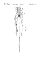
- FIG. 3 is a side illustration of the delivery device for the implant assembly
- FIG. 4 is a fragmented illustration of the distal region of the delivery device
- FIG. 5 is an enlarged sectional illustration of the distal region of the delivery device loaded with the implant assembly and in readiness for insertion into a patient;
- FIG. 6 is a diagrammatic illustration of the manner in which the implant may be loaded into the distal end of the delivery device
- FIG. 7 is an enlarged illustration of an embodiment of a stay and implant retention device adapted to securely engage the trailing end of the implant assembly
- FIG. 8 is a sectional illustration of the trailing end of an implant assembly contained within the delivery device and in engagement with the stay and retention device;
- FIG. 9 is an illustration of the retention device as seen along the line 9 — 9 of FIG. 8;
- FIGS. 10A-10C are diagrammatic illustrations of the process by which an implant may be deployed without releasing the implant and in a manner that enables the implant to be recaptured for repositioning or removal;
- FIG. 11 is an illustration of the control handle of the deployment device
- FIG. 11A is a sectional illustration through the control handle as seen along the line 11 A— 11 A of FIG. 11;
- FIG. 12 is an illustration of the internal shift tube of the handle
- FIG. 13 is an exploded illustration of the handle and its internal components
- FIG. 14 is a longitudinal sectional illustration of the handle with several components omitted for clarity of illustration.
- FIG. 15 is an enlarged sectional view of the connection between the distal end of the slide and its connection to the sheath of the delivery device.
- FIG. 1 illustrates, diagrammatically, a blood vessel, such as an artery 2 , in which a tubular implant assembly 4 has been placed to serve as a reinforcing liner in the region of an aneurysm 6 .
- the aneurysm 6 defines a weakened region of the wall of the artery and may be susceptible to rupture and consequent hemorrhaging under the influence of arterial blood pressure.
- the implant assembly 4 is adapted to be placed endoluminally, as by radially contracting it within the sheath of a delivery catheter, inserting the catheter into a blood vessel to access the aneurysm, positioning the device within the aneurysm and then releasing the implant assembly 4 into engagement with healthy arterial tissue beyond each end of the aneurysm.
- the implant assembly 4 may be considered as having a leading end 3 and a trailing end 5 .
- the leading end of the implant assembly 4 also may be considered as being “upstream” and the trailing end as “downstream”.
- FIG. 2 illustrates, generally, an exemplary implant assembly 4 that may be used in the practice of the present invention.
- the assembly includes an elongate flexible tubular graft 8 that may be of woven or other conventional vascular graft construction.
- the implant includes an anchor assembly that is connected to the graft 8 to maintain the ends of the graft 8 open as well as to facilitate recapture of the implant assembly 4 within the delivery device to enable repositioning or withdrawal of the graft.
- the anchor assembly may include a variety of configurations including that illustrated in FIG. 2 having a pair of resiliently expandable anchors including a leading anchor 10 and a trailing anchor 12 .
- Each of the anchors 10 , 12 may be formed from a suitable wire such as MP 35 N alloy in a zigzag configuration that defines a circumferential configuration.
- the anchors 10 , 12 may be attached to the graft 8 by a combination of sutures 14 and by passing portions of the wire from which the anchors 10 , 12 are made through openings or interstices in the fabric graft.
- FIG. 2 illustrates a tubular implant in a relaxed configuration in which the anchors 10 , 12 have expanded to the extent permitted by the dimensions of the graft 8 .
- the anchor and graft are selected with respect to the diameter of the body lumen in which they are to be placed so as they are expanded they will firmly and securely engage the lumen of the vessel.
- the implant 4 can be contracted radially to a compact, low profile configuration insertable into the distal end of the delivery device, as described below.
- the implant assembly 4 also includes a connection between the leading and trailing anchors 10 , 12 in the form of elongate struts 16 .
- the struts may be attached to the outer surface of the graft 8 by the sutures 14 that also secure the struts at their junctions with the anchors 10 , 12 and the graft 8 .
- the struts 16 also may be attached above their lengths to the exterior surface of the graft 8 by heat bonding.
- FIG. 2A shows, in greatly enlarged detail, the construction for the struts 16 .
- the struts preferably include an inner core wire 17 surrounded by a helical coil 19 wrapped tightly about the core wire 17 . The coil is wrapped in a thin tube of thermoplastic polymeric material 21 .
- the polymeric layer may comprise polypropylene, applied as a tube about the coil 19 and then heated sufficiently to enable the polypropylene to begin to melt and flow into close intimacy with the turns of the coil 19 .
- the polymeric layer may be applied, for example, in the form of tubing.
- the polymeric layer 21 may be formed from the same or a different polymeric material from which the graft 8 is formed.
- the strut may be attached firmly to the graft by heat bonding the polymeric covering directly to the graft material, as suggested in FIG. 2 A. With this arrangement, the struts may be attached securely along their full lengths to the graft 8 to provide full support for the graft 8 .
- the core wire 17 and wire from which the coil 19 is formed may be formed from MP 35 N alloy.
- the construction of the struts provides enhanced rigidity after the device is assembled while at the same time allowing the device to collapse to a low profile.
- a strut so constructed is considered to have sufficient radiopacity to permit adequate X-ray or fluoroscopic visualization of the struts when implanted in the abdominal aorta. Should it be desired to add a radiopaque filler material to the polymeric material 21 , that may enhance the radiopacity.
- the leading anchor 10 preferably is provided with hooks 15 arranged to project radially outwardly to engage the healthy tissue of the vessel into which the implant is placed.
- hooks 15 arranged to project radially outwardly to engage the healthy tissue of the vessel into which the implant is placed.
- a variety of hook configurations may be employed, including those described in the above-referenced patent applications.
- the delivery device is shown in FIG. 3 and includes an elongate flexible shaft 18 and a control handle 20 .
- the shaft includes an elongate flexible sheath 22 (FIGS. 4, 6 ) formed from a suitable polymeric material.
- the leading end of the sheath 22 may be formed to include an enlarged diameter pod 23 adapted to receive the compacted, low profile implant assembly 4 .
- the distal end of the pod 23 may be provided with a radiopaque marker band 25 (FIG. 6 ).
- the shaft also includes a positioning tube 24 that extends through the sheath 22 and has, at its leading end, a flexible tapered dilator 26 .
- the rear portion of the dilator 26 is dimensioned to be engaged with the distal end of the pod (FIG.
- a stay 28 is secured to the positioning tube 24 rearward of the dilator 26 .
- the trailing end of the dilator 26 is dimensioned to be received within the lumen at the leading end of the sheath 22 .
- the positioning tube 24 is longer than the combined length of the sheath 22 and the control handle 20 so that, when assembled, the trailing end of the positioning tube 24 can protrude rearwardly from the control handle 20 while the dilator 26 is forward of the end of the sheath.
- the positioning tube 24 is open at its leading and trailing ends and is adapted to receive a guidewire 32 through the lumen of the tube 24 .
- the trailing end of the positioning tube 24 preferably is provided with a luer fitting 34 .
- the stay 28 has openings to enable fluid to pass beyond the stay.
- FIG. 5 illustrates, in longitudinal cross-section, the leading end of the device with the compacted implant assembly 4 contained within the pod 23 of the sheath 22 .
- the implant 4 will be disposed about a portion of the positioning tube 24 .
- the trailing anchor 12 will be in abutting engagement with the stay 28 when the device is so loaded.
- the stay 28 engages the trailing anchor 12 to maintain the position of the implant assembly 4 as the sheath 22 is withdrawn.
- the stay 28 functions in conjunction with an anchor retainer 36 disposed just forwardly of the stay 28 (FIGS. 7 and 8 ).
- the stay 28 and anchor retainer 36 may be considered to comprise an implant retainer.
- the anchor retainer 36 may take the form of one or more radially extending spokes 38 attached to a central hub 40 .
- the anchor retainer 36 may be mounted on the positioning tube 24 or may be formed as an integral part of the stay 28 . As can be seen most clearly in FIG. 8, when the implant assembly 4 is engaged with the delivery device, the spokes 38 of the anchor retainer 36 engages the trailing ends of the anchor 12 within the region defined by the bends 42 (FIGS. 8 and 9 ). Cooperation of the trailing anchor 12 with the stay 28 and anchor retainer 36 effectively secure the implant assembly 4 to the positioning tube 24 to prevent longitudinal movement between the two. The implant assembly, therefore, can be maintained in position by maintaining the position of the positioning tube 24 while permitting the sheath to be withdrawn or advanced as desired.
- FIG. 6 illustrates, diagrammatically, the configuration of the system when the implant assembly 4 is loaded into the delivery device.
- the positioning tube 24 is extended through the sheath 22 with its leading end extending beyond the distal end of the pod 23 so that the stay 28 and retention device 36 extend slightly beyond the leading end of the pod 23 .
- a loading funnel 44 is placed about the positioning tube 24 with the trailing end of the funnel communicating with the leading end of the pod 23 .
- the implant assembly 4 is placed over the leading end of the positioning tube 24 such that the trailing bends 42 of the trailing anchor 12 are disposed against the stay 28 .
- the implant assembly is pushed into the funnel 44 to compress the trailing end of the anchor 12 and to move the anchor 12 , stay 28 and retention device 36 into the leading end of the pod.
- the implant assembly passes through the funnel 44 it is progressively constricted to a low profile about the positioning tube 24 and is withdrawn into the pod 23 in a compressed, low profile configuration.
- the loading continues until the trailing end of the dilator 26 has been brought into engagement with the leading end of the pod 23 (FIG. 5 ).
- the dilator 26 and pod 23 are configured to present a relatively smooth transition to minimize trauma as the device is advanced into and through the patient's vasculature. So loaded, the implant and its delivery device are in readiness to be inserted and advanced into the patient's vasculature to deploy and release the device.
- the device can be inserted into the patient's vasculature with the aid of a guidewire 32 .
- the guidewire may be placed in the blood vessel separately in a preliminary procedure.
- the delivery device then is advanced into the patient's blood vessel, for example, as through the femoral artery, when placing an implant to treat an abdominal aortic aneurysm.
- the guidewire may be advanced independently toward and through the region to be treated.
- the delivery catheter then may be advanced over the guidewire until the implant assembly is in its intended location in the blood vessel.
- the device In the case of an abdominal aortic aneurysm, the device would be located so that the leading anchor 10 is located upstream of the region of the aneurysm such that the implant, when deployed, can pass through the aneurysm thereby lining the artery.
- the position of the positioning tube 24 With the delivery device so placed, the position of the positioning tube 24 is maintained while the sheath 22 is withdrawn.
- the stationary stay 28 maintains engagement with the trailing end of the anchor 12 in the manner described above, thereby preventing rearward movement of the implant assembly while the sheath is withdrawn.
- the anchor expands into engagement with the inner luminal surface of the blood vessel while simultaneously expanding the distal end of the graft.
- the implants are characterized in their ability to be removed from or repositioned within the patient prior to completion of the deployment process.
- the deployment process can be reversed to recapture the implant and reposition or remove it.
- progressive withdrawal of the sheath 22 and pod 23 exposes progressive lengths of the implant to enable the implant to expand into contact with the blood vessel wall.
- fluoroscopic visualization methods can be used to determine if the implant is being positioned as desired.
- the sheath is withdrawn along the entire length of the implant, thereby releasing the implant and allowing it to expand into contact with the blood vessel along the entire length of the implant.
- the sheath can be advanced to recapture the implant. Since, in each embodiment, the implant includes a connected anchor assembly along the entire length of the graft, compression of the trailing end of the graft, such as be advancing the sheath, allows the radial compression force to be communicated distally. As a result, the sheath may be advanced over the entire implant assembly, progressively collapsing and recapturing the implant.
- FIGS. 10A-10C depict the implant deployment process described above.
- FIG. 10A illustrates an implant 4 having anchors 10 , 12 contained within the pod and disposed in an artery in readiness for deployment.
- FIG. 10B illustrates the device with the sheath withdrawn and with the leading anchor in engagement with the blood vessel.
- FIG. 10C illustrates a further stage of the deployment but with the trailing end of the implant maintained in engagement with the stay and retention device within the distal end of the pod. In the latter configuration, the leading end of the implant 4 has been deployed and has seated against the wall of the blood vessel. If at this point it is determined, such as by fluoroscopic visualization, that repositioning or removal of the implant is required, the sheath can be advanced distally to progressively recapture the implant.
- the sheath 22 can be advanced relative to the positioning tube 24 causing compression and recapture of a portion of the implant 4 .
- the compression forces on the proximal end of the implant are transferred progressively to its distal end by the struts 16 causing the leading end of the implant 4 to begin contracting as well.
- the sheath has been advanced over the entire length of the implant. In so doing, the implant has been removed from contact with the vessel wall and can be removed from the patient or positioned at a different location.
- the control handle is associated with the sheath 22 and positioning tube 24 to perform several functions including (1) the advancement or withdrawal of the sheath 22 relative to the positioning tube 24 and implant assembly 4 , (2) providing a means by which liquid can be delivered into and through the sheath 22 and (3) to limit the relative ranges of movement between the sheath and the positioning tube to prevent inadvertent, premature release of the implant assembly 4 .
- the control handle is securely, but adjustably connectible to the positioning tube 24 to fix the positioning tube 24 relative to the handle.
- the trailing end of the sheath is contained within the control handle and is connected to a slide mechanism by which the sheath can be withdrawn or advanced relative to the handle and the positioning tube.
- the slide mechanism in the handle includes a gated slide arrangement by which the rearward movement of the slide is limited by a gating arrangement so that the sheath cannot be withdrawn sufficiently to completely release the implant assembly.
- the control handle In order to release the implant, the control handle must be operated in a manner that releases the slide to permit further rearward movement sufficient to uncover and completely release the trailing end of the anchor.
- the arrangement prevents continuous direct movement of the slide from the captured position to the release position and assures that the physician will have opportunity to evaluate the position and orientation of the partially deployed graft while avoiding inadvertent premature release.
- the control handle 20 includes an elongate, generally tubular outer housing 50 that may be formed from a pair of molded components, including an upper housing portion 50 a and a lower housing portion 50 b .
- the housing portions 50 a , 50 b may be molded from any of a variety of suitable polymeric materials.
- Each of the upper and lower housing portions may be considered to include a central, longitudinally extending cylindrical portion 56 a , 56 b that, when the housing portions 50 a , 50 b are mated, define a generally circular cross-section.
- Each of the upper and lower housing portions 50 a , 50 b also includes a pair of opposed laterally projecting, longitudinally extending ribs that, when the portions 50 a , 50 b are assembled, will define side ribs 52 to facilitate gripping of the control handle 50 (FIG. 9 A).
- the control handle thus has a greater widthwise dimension than heightwise, in cross-section. That configuration facilitates gripping of the device and also enables the physician to place the device against a supporting surface to help stabilize the device for operation with one hand.
- each of the housing portions 50 a , 50 b include end walls 66 a , 66 b .
- Each end wall 66 a , 66 b has a rearward extension that defines a collett finger 68 A, 68 B.
- the facing surfaces of each collett finger include grooves that, when the parts are mated, define a passage receptive to the rear portion of the positioning tube 24 .
- the collett fingers 68 a , 68 b may be tightened about the positioning tube 24 by a nut 70 engageable with threads formed on the outer surface of the collett fingers 68 a , 68 b.
- the upper housing portion includes an elongate slot 72 that provides access to the interior of the housing for a slide button by which a portion of the internal control mechanism is operated.
- the outer housing 50 of the control handle contains a gating tube, indicated generally at 76 (FIG. 11 ).
- the gating tube 76 is rotatably contained within the cylindrical portions 56 of the outer housing 50 .
- the gating tube 76 also may be formed from a pair of molded halves, 76 a , 76 b (FIG. 11 ).
- the halves 76 a , 76 b are formed so that when assembled, the leading end of the gating tube will include an integral knob 78 having an end wall 80 and an aperture 82 formed centrally in the end wall 80 .
- the rear end of the gating tube 76 is open.
- the gating tube halves 76 a , 76 b also are formed to include circumferential ribs 84 , 86 that are receivable within arcuate slots 88 , 90 formed in the upper and lower housing portions 50 A, 50 B (FIG. 11 B).
- the gating tube 76 can be rotated within the housing 50 by manipulation of a knob 78 .
- the halves 76 a , 76 b of the gating tube 76 also are formed so that when combined they will define a gating channel including two longitudinal, sequential slots 92 , 94 .
- the more forward slot 92 may have, at its forwardmost end, a circumferentially enlarged portion 96 .
- a similarly circumferentially enlarged region 98 is formed at the transition between the forward slot 92 and the immediately adjacent rearward slot 94 .
- the circumferentially enlarged slot portions 96 , 98 define circumferential detent surfaces 100 , 102 , 104 , 106 .
- a slide 108 is slidably contained within the gating tube 76 .
- the slide 108 includes an upwardly projecting boss 110 that is connectible to a downwardly extending tongue 112 of the slide button 74 .
- the boss 110 protrudes radially through one of the slots 92 , 94 in the gating tube and into the slot 72 in the outer housing 50 .
- the boss 110 and mated portion of the slide button 74 cooperatively extends through the slot 72 of the housing 50 and an aligned portion of the gating channel.
- the transition region 98 and detent surface 106 are disposed to limit rearward movement of the slide 108 to a position in which the retention device 36 remains within the pod.
- the slide is permitted to move only within one of the slots 92 , 94 . Consequently, when the slide 108 has been retracted fully to the rear end of slot 92 and its boss 110 is engagement with the detent surface 106 , further rearward movement of the slide 108 cannot occur until the gating tube 76 has been rotated to align the boss 110 with the slot 94 .
- the circumferential extent of the transitional opening 98 is dimensioned to receive the boss 110 and permit such rotation.
- the slide 108 is connected to the rear end of the sheath as illustrated in FIGS. 14 and 15.
- the device is constructed so that in addition to providing control over the extent to which the sheath is extended or withdrawn, means also is provided to enable liquid to be communicated to and through the sheath, for emission at the end of the pod.
- FIG. 13 shows the slide in its most forward position in which the boss 110 is disposed in the circumferentially enlarged portion 96 between detent surfaces 100 , 102 .
- the knob 78 having been rotated counterclockwise (as viewed from a rearward position and suggested by the arrow 79 )
- the slide 108 is locked in that position, the boss 110 being captured between the detent surfaces 100 , 102 .
- the gating tube 76 In order to permit the slide 108 to be withdrawn rearwardly, the gating tube 76 must be rotated clockwise to align the boss 110 with the slot 92 in the gating tube 76 .
- the slide 108 includes an inner wall 114 with a central aperture 116 through which the positioning tube 24 extends.
- a liquid seal between the inner wall 114 and the positioning tube 24 is effected by an O-ring 118 contained in a recess in the front of the inner wall 114 .
- the O-ring 118 is secured with respect to the inner wall 114 by a cap 120 secured to the front side of the inner wall 114 to capture the O-ring 118 .
- the O-ring and positioning tube 24 are configured to enable the positioning tube 24 to slide freely within the O-ring 118 yet to maintain an effective liquid seal about the tube 24 .
- the portion of the slide 108 forward of the inner wall 114 defines a chamber 122 that may be enclosed by a front cap 124 attached, as by ultrasonic welding, to the front end of the slide 108 .
- the cap has a central aperture.
- the sheath 22 extends through the aperture and is attached, at its rearward end, to the front cap 124 as by a circumferential flange 126 to assure a secure connection to the end cap 124 .
- the positioning tube 24 extends through the central aperture of the end cap 124 and through the sheath 22 .
- the outer diameter of the positioning tube 24 is less than the inner diameter of the sheath 22 to define an annular lumen 128 that extends all the way to the opening at the leading end of the pod.
- liquids can be injected through the lumen 128 .
- the liquid is communicated to the chamber 122 and then to the lumen 128 by a flexible tube having a leading end connected to a port 132 in the inner wall 114 of the slide 108 .
- the tube 130 may be helically coiled about the positioning tube 24 and emerges from the rear portion of the control handle.
- the tube 130 may be connected to a three-way stopcock 134 , as described below. Liquid injected through the tube 130 thus will flow into the chamber 122 and then into the lumen 128 for delivery at the leading end of the device.
- the stay 28 is provided with holes through which the liquid may flow.
- the device is loaded with the implant assembly by manipulating the controls to withdraw the sheath sufficiently rearwardly so that the stay 28 and anchor retainer 36 are exposed beyond the leading end of the pod 23 .
- the longitudinal position of the support rod 24 is preliminarily set and secured relative to the control handle by tightening the nut about the collett at the rear end of the handle.
- the trailing end of the implant assembly then is engaged with the stay and retention device and the sheath is advanced to draw the implant assembly 4 into the pod 23 . It may be desirable for the physician to assure that the control knob 78 has been rotated fully counterclockwise, indicated at arrow 79 to lock the slide button 74 within the region 96 of the gating tube 76 .
- the device then may be advanced over a previously placed guidewire that serves to guide the device into the patient's vasculature. Should it be desired to replace the initial guidewire with a different guidewire (for example, a steerable guidewire) such a guidewire exchange can be performed through the positioning tube 24 . With the guidewire having been advanced and manipulated to the intended deployment site, the delivery catheter than can be advanced over the guidewire. Should the physician desire to inject radiopaque contrast liquid at any time, a syringe with contrast liquid can be fitted to the stopcock 134 and injected into and through the annular lumen between the sheath 22 and the positioning rod 24 . The sheath may be withdrawn slightly to facilitate flow of contrast liquid into the blood vessel.
- a syringe with contrast liquid can be fitted to the stopcock 134 and injected into and through the annular lumen between the sheath 22 and the positioning rod 24 . The sheath may be withdrawn slightly to facilitate flow of contrast liquid into the blood vessel.
- the control knob 78 When it has been determined that the implant is in the desired position and orientation for release, the control knob 78 is rotated to align the gating tube 76 to permit the slide to be withdrawn. The physician withdraws the sheath by operation of the slide button 74 . At any time during the procedure additional contrast liquid may be injected. The slide 108 can only be withdrawn until it engages the detent surface 106 .
- the support tube 24 When setting up the device, the support tube 24 is secured in a position such that when the slide 108 has been brought to its pre-release position, in engagement with the detent surface 106 , the stay 28 and retention device 36 will remain within the pod in engagement with the trailing end of the implant assembly.
- the gating tube 76 rotated to permit further rearward advancement of the slide 108 .
- the stay 28 and retention device will be disposed outside of the pod 23 and the implant will have been released. If the physician determines, before release, that the position of the implant assembly is not as desired, the implant assembly can be recaptured as described above either to be repositioned or withdrawn.
- the control handle may be provided with a detent 136 formed integrally with the slide (FIG. 15 ).
- the detent may be disposed so that when the slide has been brought fully rearwardly, it snaps into engagement with the free rear edge of the gating tube 76 .
- the leading surface of the detent 136 may be formed at somewhat of an angle so that, if desired, the slide can be readvanced forwardly, but only under a substantial force that necessarily will be noticed by the physician.
- the invention provides an arrangement by which a tubular implant assembly may be advanced into a body lumen in a manner that reduces significantly the risk of the device being released prematurely before the position and orientation of the device has been verified.
- the device and method that it practices requires a deliberate manipulation on the part of the physician in order to release the device into the body lumen.
- the implant assembly can be easily recaptured for repositioning or withdrawal.
Landscapes
- Health & Medical Sciences (AREA)
- Engineering & Computer Science (AREA)
- Biomedical Technology (AREA)
- Cardiology (AREA)
- Oral & Maxillofacial Surgery (AREA)
- Transplantation (AREA)
- Heart & Thoracic Surgery (AREA)
- Vascular Medicine (AREA)
- Life Sciences & Earth Sciences (AREA)
- Animal Behavior & Ethology (AREA)
- General Health & Medical Sciences (AREA)
- Public Health (AREA)
- Veterinary Medicine (AREA)
- Prostheses (AREA)
- Media Introduction/Drainage Providing Device (AREA)
Abstract
A delivery device for intraluminally positioning and controllably releasing a vascular prosthesis includes an elongate delivery sheath and a control handle at the proximal end of the device. The handle has components movable and arranged to define at least three relative positions including (1) an implant capture position in which the sheath fully encloses and contains the implant, (2) an intermediate position in which the implant is partially deployed but in which the trailing end of the implant remains attached to the delivery device, and (3) a release position in which the implant has been freed from the delivery device and fully released within the blood vessel. The movable parts of the handle include a shifting mechanism that must be operated deliberately through a detent by the physician to enable the handle to be manipulated from one position to the other.
Description
The invention relates to delivery catheters for delivering and deploying an endoluminal implant to a remote site within a body lumen.
It has long been accepted medical practice to treat a variety of vascular disorders in a surgical procedure that involves surgical exposure of the portion of the patient's vascular system to be treated and placement of a vascular graft at that site. In order to reduce the risks inherent in such surgery, various devices and techniques for advancing and deploying a vascular graft without requiring a full surgical procedure have been under development. Among those techniques is to provide a tubular implant assembly that can be radially contracted to a low profile (small effective cross-sectional diameter) and loaded into a delivery catheter to enable the catheter to be advanced through the patient's vasculature to deliver and deploy the implant at its intended site of placement. When located at the intended deployment site, the catheter is operated to eject the implant so that it can deploy to its radially expanded configuration in engagement with the inner surface of the blood vessel.
Among the difficulties presented in such endoluminal placement of an implant is that the implant and catheter are not directly visible to the physician. Therefore, in order for the physician to determine the location of the catheter and the implant, as well as its position within the blood vessel, fluoroscopic techniques are used. Radiopaque elements may be provided on one or both of the implant and delivery catheter. Additionally, radiopaque contrast liquid may be injected into the blood vessel. However, even if the predeployment position of the implant appears to be satisfactory, further manipulation of the delivery catheter in order to deploy the implant, may result in shifting of the graft and misplacement either as to its location, orientation or both.
European patent applications Ser. No. 94116805.6 filed Nov. 10, 1994 (Publication No. 0657147) and Ser. No. 95114543.2 filed Sep. 15, 1995 (Publication No. 0701800A1) describe a recapturable prosthetic implant system that includes an implant and a delivery device in which a substantial portion of the implant may be ejected from the delivery device sufficiently to enable determination whether the implant is in its proper location, orientation and of the correct size. The implant and delivery system are configured to enable the implant to be retracted into the delivery device in the event that the location or orientation is improper. With the implant recaptured, the delivery device can be manipulated into the proper position. The implant then can be partially deployed and its position and orientation again determined. When the implant is located as desired, the delivery device is operated to fully release the implant. The construction of the implant is such that it will remain in the deployed position within the blood vessel.
The delivery device is in the form of a catheter having an elongate tubular sheath arranged to contain the implant in its low profile within the distal end of the sheath. The device also includes an elongate positioning member that extends through the sheath and implant and engages with the trailing end of the implant. The positioning member has a hollow lumen adapted to receive a guidewire so that the delivery device can be advanced into and navigated through the patient's vascular system in an over-the-wire technique. When the delivery system and implant have been advanced to the intended site of deployment, the positioning member is held stationary while the sheath is withdrawn. As the sheath is withdrawn, the implant is progressively exposed and expands radially toward engagement with the wall of the blood vessel.
An end of the implant remains attached to the positioning member and remains so until the sheath has been withdrawn past the connection of the implant, at which point the implant is released. At any time before the point of release, the sheath can be readvanced over the implant to recapture the implant.
The implant, for example, may include a tubular synthetic graft having leading and trailing ends and a resilient, self-expanding anchor assembly, connected to the graft, that is compressible to a low profile and can expand resiliently to an enlarged diameter. The anchor assembly may include an anchor at each end. Each anchor may be formed generally in the configuration of a continuous zigzag wire arranged in a tubular configuration. Portions of the anchors at the opposite ends of the implant are connected to two or more longitudinal struts. The anchors may be provided with one or more radially outward protruding hooks adapted to engage the blood vessel wall under the influence of the resilient anchor to enhance the resistance of the anchor to migration once the graft has been released from the delivery device.
There is some risk that as the deployment of the device approaches its completion, there may be premature accidental release of the implant. It would be desirable, therefore, to provide a means and method by which such accidental premature release could be prevented.
The delivery catheter is provided with a control handle at its proximal end. The handle has movable components connected respectively to the sheath and the positioning member to control their relative longitudinal movement and position. The handle components are arranged to define at least three relative positions of the sheath and positioning member including (1) an implant capture position in which the sheath fully encloses and contains the implant, (2) a further stage of the implant capture state in which the implant is partially deployed from the sheath but in which the trailing end of the implant remains attached to the delivery device, and (3) a release configuration in which the implant has been ejected from the sheath sufficiently to enable it to be freed from the sheath and fully released within the blood vessel. In the illustrative embodiment, the movable parts of the handle include a shifting mechanism that must be operated deliberately by the physician to enable the handle to be manipulated from one position to the other. Thus, the physician can be confident that the implant will not be deployed prematurely and that it will be released only when the physician is satisfied with its placement and position. The device is ergonomic and can be operated entirely by feel. Thus, the physician is relieved of continuous visual checking of the relative positions of the sheath and the positioning member.
It is among the general objects of the invention to provide an improved delivery device and method for an endoluminal implant that enables the implant to be deployed in partial progressive stages.
Another object of the invention is to provide an improved delivery device for an endoluminal implant in which inadvertent release of the implant is avoided.
A further object of the invention is to provide an improved delivery device for an endoluminal implant that facilitates recapture of the implant.
A further object of the invention is to provide a device of the type described that can be operated substantially by feel and without requiring that the physician divert attention from the other aspects of the procedure.
The foregoing and other objects and advantages of the invention will be appreciated more fully from the following further description, with reference to the accompanying drawings wherein:
FIG. 1 is a diagrammatic illustration of a blood vessel having an aneurysm with an endoluminal tubular implant disposed within the aneurysm to reinforce the blood vessel;
FIG. 2 is an illustration of an embodiment of a single tubular implant that can be placed with the delivery device;
FIG. 2A is a greatly enlarged longitudinal section of a portion of a strut of the implant assembly;
FIG. 3 is a side illustration of the delivery device for the implant assembly;
FIG. 4 is a fragmented illustration of the distal region of the delivery device;
FIG. 5 is an enlarged sectional illustration of the distal region of the delivery device loaded with the implant assembly and in readiness for insertion into a patient;
FIG. 6 is a diagrammatic illustration of the manner in which the implant may be loaded into the distal end of the delivery device;
FIG. 7 is an enlarged illustration of an embodiment of a stay and implant retention device adapted to securely engage the trailing end of the implant assembly;
FIG. 8 is a sectional illustration of the trailing end of an implant assembly contained within the delivery device and in engagement with the stay and retention device;
FIG. 9 is an illustration of the retention device as seen along the line 9—9 of FIG. 8;
FIGS. 10A-10C are diagrammatic illustrations of the process by which an implant may be deployed without releasing the implant and in a manner that enables the implant to be recaptured for repositioning or removal;
FIG. 11 is an illustration of the control handle of the deployment device;
FIG. 11A is a sectional illustration through the control handle as seen along the line 11A—11A of FIG. 11;
FIG. 12 is an illustration of the internal shift tube of the handle;
FIG. 13 is an exploded illustration of the handle and its internal components;
FIG. 14 is a longitudinal sectional illustration of the handle with several components omitted for clarity of illustration; and
FIG. 15 is an enlarged sectional view of the connection between the distal end of the slide and its connection to the sheath of the delivery device.
FIG. 1 illustrates, diagrammatically, a blood vessel, such as an artery 2, in which a tubular implant assembly 4 has been placed to serve as a reinforcing liner in the region of an aneurysm 6. The aneurysm 6 defines a weakened region of the wall of the artery and may be susceptible to rupture and consequent hemorrhaging under the influence of arterial blood pressure. The implant assembly 4 is adapted to be placed endoluminally, as by radially contracting it within the sheath of a delivery catheter, inserting the catheter into a blood vessel to access the aneurysm, positioning the device within the aneurysm and then releasing the implant assembly 4 into engagement with healthy arterial tissue beyond each end of the aneurysm.
In the following description, a direction along which the delivery device is advanced will be referred to as “leading” or “forward” and the opposite direction will be referred to as “trailing” or “rearward”. Thus, the implant assembly 4 may be considered as having a leading end 3 and a trailing end 5. When the implant assembly 4 has been advanced into and through the blood vessel from a downstream location to an upstream deployment location, the leading end of the implant assembly 4 also may be considered as being “upstream” and the trailing end as “downstream”.
FIG. 2 illustrates, generally, an exemplary implant assembly 4 that may be used in the practice of the present invention. The assembly includes an elongate flexible tubular graft 8 that may be of woven or other conventional vascular graft construction. The implant includes an anchor assembly that is connected to the graft 8 to maintain the ends of the graft 8 open as well as to facilitate recapture of the implant assembly 4 within the delivery device to enable repositioning or withdrawal of the graft. The anchor assembly may include a variety of configurations including that illustrated in FIG. 2 having a pair of resiliently expandable anchors including a leading anchor 10 and a trailing anchor 12. Each of the anchors 10, 12 may be formed from a suitable wire such as MP35N alloy in a zigzag configuration that defines a circumferential configuration. The anchors 10, 12 may be attached to the graft 8 by a combination of sutures 14 and by passing portions of the wire from which the anchors 10, 12 are made through openings or interstices in the fabric graft.
FIG. 2 illustrates a tubular implant in a relaxed configuration in which the anchors 10, 12 have expanded to the extent permitted by the dimensions of the graft 8. Preferably the anchor and graft are selected with respect to the diameter of the body lumen in which they are to be placed so as they are expanded they will firmly and securely engage the lumen of the vessel. The implant 4 can be contracted radially to a compact, low profile configuration insertable into the distal end of the delivery device, as described below.
The implant assembly 4 also includes a connection between the leading and trailing anchors 10, 12 in the form of elongate struts 16. The struts may be attached to the outer surface of the graft 8 by the sutures 14 that also secure the struts at their junctions with the anchors 10, 12 and the graft 8. The struts 16 also may be attached above their lengths to the exterior surface of the graft 8 by heat bonding. FIG. 2A shows, in greatly enlarged detail, the construction for the struts 16. The struts preferably include an inner core wire 17 surrounded by a helical coil 19 wrapped tightly about the core wire 17. The coil is wrapped in a thin tube of thermoplastic polymeric material 21. The polymeric layer may comprise polypropylene, applied as a tube about the coil 19 and then heated sufficiently to enable the polypropylene to begin to melt and flow into close intimacy with the turns of the coil 19. The polymeric layer may be applied, for example, in the form of tubing. The polymeric layer 21 may be formed from the same or a different polymeric material from which the graft 8 is formed. The strut may be attached firmly to the graft by heat bonding the polymeric covering directly to the graft material, as suggested in FIG. 2A. With this arrangement, the struts may be attached securely along their full lengths to the graft 8 to provide full support for the graft 8. The core wire 17 and wire from which the coil 19 is formed may be formed from MP35N alloy. The construction of the struts provides enhanced rigidity after the device is assembled while at the same time allowing the device to collapse to a low profile. A strut so constructed is considered to have sufficient radiopacity to permit adequate X-ray or fluoroscopic visualization of the struts when implanted in the abdominal aorta. Should it be desired to add a radiopaque filler material to the polymeric material 21, that may enhance the radiopacity.
As shown in FIG. 2 the leading anchor 10 preferably is provided with hooks 15 arranged to project radially outwardly to engage the healthy tissue of the vessel into which the implant is placed. A variety of hook configurations may be employed, including those described in the above-referenced patent applications. Reference is made to the disclosures in the above-referenced European patent applications, the disclosures of which are incorporated herein in their entireties, for additional details and embodiments of such implant assemblies.
The delivery device is shown in FIG. 3 and includes an elongate flexible shaft 18 and a control handle 20. The shaft includes an elongate flexible sheath 22 (FIGS. 4, 6) formed from a suitable polymeric material. The leading end of the sheath 22 may be formed to include an enlarged diameter pod 23 adapted to receive the compacted, low profile implant assembly 4. The distal end of the pod 23 may be provided with a radiopaque marker band 25 (FIG. 6). The shaft also includes a positioning tube 24 that extends through the sheath 22 and has, at its leading end, a flexible tapered dilator 26. The rear portion of the dilator 26 is dimensioned to be engaged with the distal end of the pod (FIG. 5) to close the open end of the pod during advancement of the delivery device as well as after the implant has been deployed to maintain the pod closed during withdrawal of the delivery device. A stay 28 is secured to the positioning tube 24 rearward of the dilator 26. The trailing end of the dilator 26 is dimensioned to be received within the lumen at the leading end of the sheath 22. The positioning tube 24 is longer than the combined length of the sheath 22 and the control handle 20 so that, when assembled, the trailing end of the positioning tube 24 can protrude rearwardly from the control handle 20 while the dilator 26 is forward of the end of the sheath. The positioning tube 24 is open at its leading and trailing ends and is adapted to receive a guidewire 32 through the lumen of the tube 24. The trailing end of the positioning tube 24 preferably is provided with a luer fitting 34. The stay 28 has openings to enable fluid to pass beyond the stay.
FIG. 5 illustrates, in longitudinal cross-section, the leading end of the device with the compacted implant assembly 4 contained within the pod 23 of the sheath 22. The implant 4 will be disposed about a portion of the positioning tube 24. The trailing anchor 12 will be in abutting engagement with the stay 28 when the device is so loaded. The stay 28 engages the trailing anchor 12 to maintain the position of the implant assembly 4 as the sheath 22 is withdrawn. The stay 28 functions in conjunction with an anchor retainer 36 disposed just forwardly of the stay 28 (FIGS. 7 and 8). The stay 28 and anchor retainer 36 may be considered to comprise an implant retainer. The anchor retainer 36 may take the form of one or more radially extending spokes 38 attached to a central hub 40. The anchor retainer 36 may be mounted on the positioning tube 24 or may be formed as an integral part of the stay 28. As can be seen most clearly in FIG. 8, when the implant assembly 4 is engaged with the delivery device, the spokes 38 of the anchor retainer 36 engages the trailing ends of the anchor 12 within the region defined by the bends 42 (FIGS. 8 and 9). Cooperation of the trailing anchor 12 with the stay 28 and anchor retainer 36 effectively secure the implant assembly 4 to the positioning tube 24 to prevent longitudinal movement between the two. The implant assembly, therefore, can be maintained in position by maintaining the position of the positioning tube 24 while permitting the sheath to be withdrawn or advanced as desired.
FIG. 6 illustrates, diagrammatically, the configuration of the system when the implant assembly 4 is loaded into the delivery device. The positioning tube 24 is extended through the sheath 22 with its leading end extending beyond the distal end of the pod 23 so that the stay 28 and retention device 36 extend slightly beyond the leading end of the pod 23. A loading funnel 44 is placed about the positioning tube 24 with the trailing end of the funnel communicating with the leading end of the pod 23. The implant assembly 4 is placed over the leading end of the positioning tube 24 such that the trailing bends 42 of the trailing anchor 12 are disposed against the stay 28. The implant assembly is pushed into the funnel 44 to compress the trailing end of the anchor 12 and to move the anchor 12, stay 28 and retention device 36 into the leading end of the pod. As the implant assembly passes through the funnel 44 it is progressively constricted to a low profile about the positioning tube 24 and is withdrawn into the pod 23 in a compressed, low profile configuration. The loading continues until the trailing end of the dilator 26 has been brought into engagement with the leading end of the pod 23 (FIG. 5). Preferably, the dilator 26 and pod 23 are configured to present a relatively smooth transition to minimize trauma as the device is advanced into and through the patient's vasculature. So loaded, the implant and its delivery device are in readiness to be inserted and advanced into the patient's vasculature to deploy and release the device.
The device can be inserted into the patient's vasculature with the aid of a guidewire 32. The guidewire may be placed in the blood vessel separately in a preliminary procedure. The delivery device then is advanced into the patient's blood vessel, for example, as through the femoral artery, when placing an implant to treat an abdominal aortic aneurysm. The guidewire may be advanced independently toward and through the region to be treated. The delivery catheter then may be advanced over the guidewire until the implant assembly is in its intended location in the blood vessel. In the case of an abdominal aortic aneurysm, the device would be located so that the leading anchor 10 is located upstream of the region of the aneurysm such that the implant, when deployed, can pass through the aneurysm thereby lining the artery. With the delivery device so placed, the position of the positioning tube 24 is maintained while the sheath 22 is withdrawn. The stationary stay 28 maintains engagement with the trailing end of the anchor 12 in the manner described above, thereby preventing rearward movement of the implant assembly while the sheath is withdrawn. As the sheath is progressively withdrawn and the trailing anchor 12 emerges from the distal end of the pod 23, the anchor expands into engagement with the inner luminal surface of the blood vessel while simultaneously expanding the distal end of the graft.
The implants are characterized in their ability to be removed from or repositioned within the patient prior to completion of the deployment process. In particular, as long as a trailing portion of the implant is maintained within the pod 23, the deployment process can be reversed to recapture the implant and reposition or remove it. As discussed above, progressive withdrawal of the sheath 22 and pod 23 exposes progressive lengths of the implant to enable the implant to expand into contact with the blood vessel wall. During this procedure, fluoroscopic visualization methods can be used to determine if the implant is being positioned as desired.
If the positioning is as desired, the sheath is withdrawn along the entire length of the implant, thereby releasing the implant and allowing it to expand into contact with the blood vessel along the entire length of the implant. However, if it is determined prior to complete withdrawal of the sheath (and concurrent release of the implant) that the implant is not positioned exactly as desired, the sheath can be advanced to recapture the implant. Since, in each embodiment, the implant includes a connected anchor assembly along the entire length of the graft, compression of the trailing end of the graft, such as be advancing the sheath, allows the radial compression force to be communicated distally. As a result, the sheath may be advanced over the entire implant assembly, progressively collapsing and recapturing the implant.
FIGS. 10A-10C depict the implant deployment process described above. FIG. 10A illustrates an implant 4 having anchors 10, 12 contained within the pod and disposed in an artery in readiness for deployment. FIG. 10B illustrates the device with the sheath withdrawn and with the leading anchor in engagement with the blood vessel. FIG. 10C illustrates a further stage of the deployment but with the trailing end of the implant maintained in engagement with the stay and retention device within the distal end of the pod. In the latter configuration, the leading end of the implant 4 has been deployed and has seated against the wall of the blood vessel. If at this point it is determined, such as by fluoroscopic visualization, that repositioning or removal of the implant is required, the sheath can be advanced distally to progressively recapture the implant. As shown in FIG. 10B, the sheath 22 can be advanced relative to the positioning tube 24 causing compression and recapture of a portion of the implant 4. The compression forces on the proximal end of the implant are transferred progressively to its distal end by the struts 16 causing the leading end of the implant 4 to begin contracting as well. In FIG. 10A, the sheath has been advanced over the entire length of the implant. In so doing, the implant has been removed from contact with the vessel wall and can be removed from the patient or positioned at a different location.
The control handle is associated with the sheath 22 and positioning tube 24 to perform several functions including (1) the advancement or withdrawal of the sheath 22 relative to the positioning tube 24 and implant assembly 4, (2) providing a means by which liquid can be delivered into and through the sheath 22 and (3) to limit the relative ranges of movement between the sheath and the positioning tube to prevent inadvertent, premature release of the implant assembly 4. The control handle is securely, but adjustably connectible to the positioning tube 24 to fix the positioning tube 24 relative to the handle. The trailing end of the sheath is contained within the control handle and is connected to a slide mechanism by which the sheath can be withdrawn or advanced relative to the handle and the positioning tube. The slide mechanism in the handle includes a gated slide arrangement by which the rearward movement of the slide is limited by a gating arrangement so that the sheath cannot be withdrawn sufficiently to completely release the implant assembly. In order to release the implant, the control handle must be operated in a manner that releases the slide to permit further rearward movement sufficient to uncover and completely release the trailing end of the anchor. The arrangement prevents continuous direct movement of the slide from the captured position to the release position and assures that the physician will have opportunity to evaluate the position and orientation of the partially deployed graft while avoiding inadvertent premature release.
The control handle 20 includes an elongate, generally tubular outer housing 50 that may be formed from a pair of molded components, including an upper housing portion 50 a and a lower housing portion 50 b. The housing portions 50 a, 50 b may be molded from any of a variety of suitable polymeric materials. Each of the upper and lower housing portions may be considered to include a central, longitudinally extending cylindrical portion 56 a, 56 b that, when the housing portions 50 a, 50 b are mated, define a generally circular cross-section. Each of the upper and lower housing portions 50 a, 50 b also includes a pair of opposed laterally projecting, longitudinally extending ribs that, when the portions 50 a, 50 b are assembled, will define side ribs 52 to facilitate gripping of the control handle 50 (FIG. 9A). The control handle thus has a greater widthwise dimension than heightwise, in cross-section. That configuration facilitates gripping of the device and also enables the physician to place the device against a supporting surface to help stabilize the device for operation with one hand.
The rear end of each of the housing portions 50 a, 50 b include end walls 66 a, 66 b. Each end wall 66 a, 66 b has a rearward extension that defines a collett finger 68A, 68B. The facing surfaces of each collett finger include grooves that, when the parts are mated, define a passage receptive to the rear portion of the positioning tube 24. The collett fingers 68 a, 68 b may be tightened about the positioning tube 24 by a nut 70 engageable with threads formed on the outer surface of the collett fingers 68 a, 68 b.
The upper housing portion includes an elongate slot 72 that provides access to the interior of the housing for a slide button by which a portion of the internal control mechanism is operated.
The outer housing 50 of the control handle contains a gating tube, indicated generally at 76 (FIG. 11). The gating tube 76 is rotatably contained within the cylindrical portions 56 of the outer housing 50. The gating tube 76 also may be formed from a pair of molded halves, 76 a, 76 b (FIG. 11). The halves 76 a, 76 b are formed so that when assembled, the leading end of the gating tube will include an integral knob 78 having an end wall 80 and an aperture 82 formed centrally in the end wall 80. The rear end of the gating tube 76 is open. The gating tube halves 76 a, 76 b, also are formed to include circumferential ribs 84, 86 that are receivable within arcuate slots 88, 90 formed in the upper and lower housing portions 50A, 50B (FIG. 11B). When the housing 50 and gating tube 76 are assembled, the gating tube 76 can be rotated within the housing 50 by manipulation of a knob 78. The halves 76 a, 76 b of the gating tube 76 also are formed so that when combined they will define a gating channel including two longitudinal, sequential slots 92, 94. The more forward slot 92 may have, at its forwardmost end, a circumferentially enlarged portion 96. A similarly circumferentially enlarged region 98 is formed at the transition between the forward slot 92 and the immediately adjacent rearward slot 94. The circumferentially enlarged slot portions 96, 98 define circumferential detent surfaces 100, 102, 104, 106.
A slide 108 is slidably contained within the gating tube 76. The slide 108 includes an upwardly projecting boss 110 that is connectible to a downwardly extending tongue 112 of the slide button 74. The boss 110 protrudes radially through one of the slots 92, 94 in the gating tube and into the slot 72 in the outer housing 50. The boss 110 and mated portion of the slide button 74 cooperatively extends through the slot 72 of the housing 50 and an aligned portion of the gating channel. The transition region 98 and detent surface 106 are disposed to limit rearward movement of the slide 108 to a position in which the retention device 36 remains within the pod. It will be appreciated, therefore, that the slide is permitted to move only within one of the slots 92, 94. Consequently, when the slide 108 has been retracted fully to the rear end of slot 92 and its boss 110 is engagement with the detent surface 106, further rearward movement of the slide 108 cannot occur until the gating tube 76 has been rotated to align the boss 110 with the slot 94. The circumferential extent of the transitional opening 98 is dimensioned to receive the boss 110 and permit such rotation.
The slide 108 is connected to the rear end of the sheath as illustrated in FIGS. 14 and 15. The device is constructed so that in addition to providing control over the extent to which the sheath is extended or withdrawn, means also is provided to enable liquid to be communicated to and through the sheath, for emission at the end of the pod. FIG. 13 shows the slide in its most forward position in which the boss 110 is disposed in the circumferentially enlarged portion 96 between detent surfaces 100, 102. In that configuration with the knob 78 having been rotated counterclockwise (as viewed from a rearward position and suggested by the arrow 79), the slide 108 is locked in that position, the boss 110 being captured between the detent surfaces 100, 102. In order to permit the slide 108 to be withdrawn rearwardly, the gating tube 76 must be rotated clockwise to align the boss 110 with the slot 92 in the gating tube 76.
As shown in detail in FIG. 15, the slide 108 includes an inner wall 114 with a central aperture 116 through which the positioning tube 24 extends. A liquid seal between the inner wall 114 and the positioning tube 24 is effected by an O-ring 118 contained in a recess in the front of the inner wall 114. The O-ring 118 is secured with respect to the inner wall 114 by a cap 120 secured to the front side of the inner wall 114 to capture the O-ring 118. The O-ring and positioning tube 24 are configured to enable the positioning tube 24 to slide freely within the O-ring 118 yet to maintain an effective liquid seal about the tube 24.
The portion of the slide 108 forward of the inner wall 114 defines a chamber 122 that may be enclosed by a front cap 124 attached, as by ultrasonic welding, to the front end of the slide 108. The cap has a central aperture. The sheath 22 extends through the aperture and is attached, at its rearward end, to the front cap 124 as by a circumferential flange 126 to assure a secure connection to the end cap 124. As shown, the positioning tube 24 extends through the central aperture of the end cap 124 and through the sheath 22. The outer diameter of the positioning tube 24 is less than the inner diameter of the sheath 22 to define an annular lumen 128 that extends all the way to the opening at the leading end of the pod. Thus, liquids can be injected through the lumen 128. The liquid is communicated to the chamber 122 and then to the lumen 128 by a flexible tube having a leading end connected to a port 132 in the inner wall 114 of the slide 108. The tube 130 may be helically coiled about the positioning tube 24 and emerges from the rear portion of the control handle. The tube 130 may be connected to a three-way stopcock 134, as described below. Liquid injected through the tube 130 thus will flow into the chamber 122 and then into the lumen 128 for delivery at the leading end of the device. The stay 28 is provided with holes through which the liquid may flow.
In operation, the device is loaded with the implant assembly by manipulating the controls to withdraw the sheath sufficiently rearwardly so that the stay 28 and anchor retainer 36 are exposed beyond the leading end of the pod 23. The longitudinal position of the support rod 24 is preliminarily set and secured relative to the control handle by tightening the nut about the collett at the rear end of the handle. The trailing end of the implant assembly then is engaged with the stay and retention device and the sheath is advanced to draw the implant assembly 4 into the pod 23. It may be desirable for the physician to assure that the control knob 78 has been rotated fully counterclockwise, indicated at arrow 79 to lock the slide button 74 within the region 96 of the gating tube 76. The device then may be advanced over a previously placed guidewire that serves to guide the device into the patient's vasculature. Should it be desired to replace the initial guidewire with a different guidewire (for example, a steerable guidewire) such a guidewire exchange can be performed through the positioning tube 24. With the guidewire having been advanced and manipulated to the intended deployment site, the delivery catheter than can be advanced over the guidewire. Should the physician desire to inject radiopaque contrast liquid at any time, a syringe with contrast liquid can be fitted to the stopcock 134 and injected into and through the annular lumen between the sheath 22 and the positioning rod 24. The sheath may be withdrawn slightly to facilitate flow of contrast liquid into the blood vessel.
When it has been determined that the implant is in the desired position and orientation for release, the control knob 78 is rotated to align the gating tube 76 to permit the slide to be withdrawn. The physician withdraws the sheath by operation of the slide button 74. At any time during the procedure additional contrast liquid may be injected. The slide 108 can only be withdrawn until it engages the detent surface 106. When setting up the device, the support tube 24 is secured in a position such that when the slide 108 has been brought to its pre-release position, in engagement with the detent surface 106, the stay 28 and retention device 36 will remain within the pod in engagement with the trailing end of the implant assembly. Only after the physician has determined that the device has been placed as desired, is the gating tube 76 rotated to permit further rearward advancement of the slide 108. When the slide has been drawn fully rearwardly, the stay 28 and retention device will be disposed outside of the pod 23 and the implant will have been released. If the physician determines, before release, that the position of the implant assembly is not as desired, the implant assembly can be recaptured as described above either to be repositioned or withdrawn.
The control handle may be provided with a detent 136 formed integrally with the slide (FIG. 15). The detent may be disposed so that when the slide has been brought fully rearwardly, it snaps into engagement with the free rear edge of the gating tube 76. The leading surface of the detent 136 may be formed at somewhat of an angle so that, if desired, the slide can be readvanced forwardly, but only under a substantial force that necessarily will be noticed by the physician.
From the foregoing, it will be appreciated that the invention provides an arrangement by which a tubular implant assembly may be advanced into a body lumen in a manner that reduces significantly the risk of the device being released prematurely before the position and orientation of the device has been verified. The device and method that it practices requires a deliberate manipulation on the part of the physician in order to release the device into the body lumen. In the event that the position is not as desired, the implant assembly can be easily recaptured for repositioning or withdrawal.
It should be understood that the foregoing description of the invention is intended merely to be illustrative thereof and that other embodiments, modifications and equivalents will be apparent to those skilled in the art without departing from its spirit.
Claims (31)
1. A device for delivering, positioning and releasing, within a body lumen, a self-expandable implant comprising:
an elongate tubular sheath for maintaining the implant in a low profile configuration, the sheath having a leading end and a trailing end and being open at its leading end;
a control handle having a body and a movable portion, the movable portion being connected to a trailing portion of the sheath, the movable portion being movable along the body of the handle to effect forward and rearward motion of the sheath with respect to the body of the handle;
an implant retainer engageable with the trailing end of the implant and being disposed to maintain the implant in a fixed position with respect to the body of the handle, the implant retainer being receivable within the sheath whereby the sheath may be moved between a forward, implant-capturing position in which the implant retainer is contained within the sheath and a rearward, implant-release position in which the implant retainer is disposed forwardly beyond the leading end of the sheath;
the movable portion of the handle being movable between a forward implant-capturing position and a rearward implant release position, the implant retainer being constructed to engage the implant to enable the leading end of the implant to self-expand as the sheath is moved toward the implant-release position and;
a detent carried by the handle to prevent continuous forward-rearward movement of the movable portion of the handle from the implant capture position to the implant release position.
2. A device as defined in claim 1 wherein the detent is manually releasable to free the movable portion of the handle for movement to a release position.
3. A device as defined in claim 2 wherein the detent is constructed so that it is movable to the release position only when the movable portion of the handle is disposed at the detent.
4. A device as defined in claim 1 further comprising a positioning tube extending through the sheath and the handle, the implant retainer being attached to the positioning tube.
5. A device as defined in claim 1 further comprising:
the handle being elongate and hollow and having forward and rearward ends;
the movable portion of the handle comprising a slide connected to the sheath, the slide being movable along the handle;
the handle further having a gating mechanism engageable with the slide to confine movement of the slide to defined segments along the length of the handle, the gating mechanism having a position in which rearward movement of the slide is limited to a position between the capture and release positions;
the gating mechanism being movably mounted to the handle to enable further rearward movement of the slide to the release position.
6. A device as defined in claim 5 further comprising:
the slide being contained within the handle;
the rear end of the sheath extending through the forward end of the handle and being connected to the slide within the handle.
7. A device as defined in claim 5 further comprising:
the gating mechanism including a gate rotatable within the handle and including at least two elongate longitudinally extending sequential, circumferentially spaced slots;
a control member disposed outside of the handle connected to the gate for effecting rotation of the gate.
8. A device as defined in claim 7 further comprising:
the rotatable gate comprising a tubular member rotatable within the handle, the tubular member having a circumferential slot disposed at a juncture of the elongate slots, the slide having a portion thereof extendable through the elongate slots and the circumferential slot.
9. A device as defined in claim 8 further comprising:
the forward-most end of the forward-most elongate slot having a circumferential slot engageable with the slide to enable locking the slide in a fully forward position.
10. A device as defined in claim 1 further comprising:
the movable portion of the control handle having a fluid chamber in communication with the lumen of the sheath and an inlet port; and
a conduit connected at one end to the inlet port and connectible at its other end to a fluid source.
11. A device as defined in claim 10 further comprising a positioning tube extending through the sheath and the handle, the positioning tube extending through the fluid chamber;
a seal carried by the movable member and engageable with the positioning tube to effect a seal about the positioning tube.
12. A device as defined in claim 11 further comprising:
a portion of the conduit being coiled about the positioning tube.
13. A device as defined in claim 1 further comprising:
means for automatically locking the movable portion of the handle to a fixed portion of the handle when the handle has been withdrawn to the implant release position.
14. A device for delivering, positioning and releasing, within a body lumen, an expandable implant comprising:
an elongate tubular sheath for maintaining the implant in a low profile configuration, the sheath having a leading end and a trailing end and being open at its leading end;
a control handle having a movable portion thereof connected to a trailing portion of the sheath, the movable portion being movable along the handle to effect forward and rearward motion of the sheath with respect to the handle;
an implant retainer engageable with the trailing end of the implant and being operatively associated with the handle to maintain the implant retainer in a fixed position with respect to the handle, the implant retainer being receivable within the sheath whereby the sheath may be moved between a forward implant capturing position in which the implant retainer is contained within the sheath and a rearward implant release position in which the implant retainer is disposed forwardly beyond the leading end of the sheath;
the movable portion of the handle being movable between a forward implant-capturing configuration and a rearward implant release configuration;
a positioning tube extending through the sheath and the handle, the implant retainer being attached to the positioning tube;
the positioning tube being movable along the longitudinal axis of the device; and
a locking element carried by the handle for locking the positioning tube in a selected position with respect to the handle.
15. A device as defined in claim 14 wherein the locking element comprises a collett disposed at the rear end of the handle, the collett receiving the rearward portion of the positioning tube and a locking nut to releasably tighten the collett about the positioning tube.
16. A method for selectively delivering, positioning and releasing, within a body lumen, a self-expandable implant having leading and trailing ends comprising:
providing an elongate tubular sheath for maintaining the implant in a low profile configuration, the sheath having a leading end and a trailing end and being open at its leading end to receive the implant, an implant retainer engageable with the trailing end of the implant to retain the trailing end of the implant in a fixed position while enabling the sheath to be withdrawn rearwardly relative to the implant retainer and implant, the method further comprising:
inserting the sheath and implant retainer together with the implant contained within the sheath, into the body lumen and advancing them as a unit to a location in the body lumen;
providing a detent to prevent direct continuous movement of the sheath from a capture position to a release position;
withdrawing the sheath to the detent between the captured and release positions while exposing the leading end of the implant to enable the leading end of the implant to self-expand;
while in the detent configuration, determining whether the implant is in a desired position and orientation; and
thereafter selectively (1) moving the detent to permit the sheath to be withdrawn to a release position or (2) without shifting the detent, returning the sheath to the capture position.
17. A device for delivering, positioning and releasing, within a body lumen, a self-expandable implant comprising:
an elongate tubular sheath for maintaining the implant in a low profile configuration, the sheath having a leading end and a trailing end and being open at its leading end;
a control handle having a body and a movable portion, the movable portion being connected to a trailing portion of the sheath, the movable portion being movable along the body of the handle to effect forward and rearward motion of the sheath with respect to the body of the handle;
means, engageable with the trailing end of the implant, for maintaining the implant in a fixed position with respect to the body of the handle, said means being receivable within the sheath whereby the sheath may be moved between a forward, implant-capturing position in which said means is contained within the sheath and a rearward, implant-release position in which said means is disposed forwardly beyond the leading end of the sheath;
the movable portion of the handle being movable between a forward implant-capturing position and a rearward implant release position, said means being constructed to engage the implant to enable the leading end of the implant to self-expand as the sheath is moved toward the implant-release position and;
a detent carded by the handle to prevent continuous forward-rearward movement of the movable portion of the handle from the implant capture position to the implant release position.
18. A device as defined in claim 17 wherein the detent is manually releasable to free the movable portion of the handle for movement to the release position.
19. A device as defined in claim 17 wherein the detent is constructed so that it is movable to the release position only when the movable portion of the handle is disposed at the detent.
20. A device as defined in claim 17 further comprising a positioning tube extending through the sheath and the handle, said means being attached to the positioning tube.
21. A device as defined in claim 17 further comprising:
the movable portion of the control handle having a fluid chamber in communication with the lumen of the sheath and an inlet port; and
a conduit connected at one end to the inlet port and connectable at its other end to a fluid source.
22. A device as defined in claim 21 further comprising a positioning tube extending through the sheath and the handle, the positioning tube extending through the fluid chamber;
a seal carried by the movable member and engageable with the positioning tube to effect a seal about the positioning tube.
23. A device as defined in claim 17 further comprising:
means for automatically locking the movable portion of the handle to a fixed portion of the handle when the handle has been withdrawn to the implant release position.
24. A device for delivering, positioning and releasing, within a body lumen, an expandable implant comprising:
an elongate tubular sheath for maintaining the implant in a low profile configuration, the sheath having a leading end and a trailing end and being open at its leading end;
a control handle having a movable portion thereof connected to a trailing portion of the sheath, the movable portion being movable along the handle to effect forward and rearward motion of the sheath with respect to the handle;
means, engageable with the trailing end of the implant and being operatively associated with the handle, for maintaining the implant in a fixed position with respect to the handle, said means being receivable within the sheath whereby the sheath may be moved between a forward implant capturing position in which said means is contained within the sheath and a rearward implant release position in which said means is disposed forwardly beyond the leading end of the sheath;
the movable portion of the handle being movable between a forward implant-capturing position and a rearward implant release position;
a positioning tube extending through the sheath and the handle, said means being attached to the positioning tube;
the positioning tube being movable along the longitudinal axis of the device; and
a locking element carried by the handle for locking the positioning tube in a selected position with respect to the handle.
25. A device as defined in claim 24 further comprising:
a slide being contained within the handle;
the trailing end of the sheath extending through the forward end of the handle and being connected to the slide within the handle.
26. A device as defined in claim 25 further comprising:
a gating mechanism including a gate rotatable within the handle and including at least two elongate longitudinally extending sequential, circumferentially spaced slots;
a control member disposed outside of the handle connected to the gate for effecting rotation of the gate.
27. A device as defined in claim 26 further comprising:
the rotatable gate comprising a tubular member rotatable within the handle, the tubular member having a circumferential slot disposed at a juncture of the elongate slots, the slide having a portion thereof extendable through the elongate slots and the circumferential slot.
28. A device as defined in claim 27 further comprising:
the forward-most end of the forward-most elongate slot having a circumferential slot engageable with the slide to enable locking the slide in a fully forward position.
29. A device as defined in claim 24 further comprising:
a portion of a conduit being coiled about the positioning tube.
30. A device as defined in claim 24 wherein the locking element comprises a collett disposed at the rear end of the handle, the collett receiving a rearward portion of the positioning tube and a locking nut to releasably tighten the collett about the positioning tube.
31. A device as defined in claim 1 further comprising:
the handle being elongate and hollow and having forward and rearward ends;
the movable portion of the handle comprising a slide connected to the sheath, the slide being movable along the handle;
the handle further having a gating mechanism engageable with the slide to confine movement of the slide to defined segments along the length of the handle, the gating mechanism having a position in which rearward movement of the slide is limited to a position between the capture and release positions;
the gating mechanism being movably mounted to the handle to enable further rearward movement of the slide to the release position.
Priority Applications (8)
| Application Number | Priority Date | Filing Date | Title |
|---|---|---|---|
| US08/751,087 US6395017B1 (en) | 1996-11-15 | 1996-11-15 | Endoprosthesis delivery catheter with sequential stage control |
| AU51779/98A AU738703B2 (en) | 1996-11-15 | 1997-11-13 | Endoprosthesis delivery catheter with sequential stage control |
| JP52278298A JP4090509B2 (en) | 1996-11-15 | 1997-11-13 | Sequential stepwise controllable endoprosthesis delivery catheter |
| EP97946653A EP0957824B1 (en) | 1996-11-15 | 1997-11-13 | Endoprosthesis delivery catheter with sequential stage control |
| DE69724150T DE69724150T2 (en) | 1996-11-15 | 1997-11-13 | INTRODUCTION CATHETER FOR A FINAL PROSTHESIS WITH STEP-BY-STEP CONTROL |
| ES97946653T ES2202646T3 (en) | 1996-11-15 | 1997-11-13 | ENDOPROTESIS TRANSPORTATION CATHETER WITH SEQUENTIAL STAGE CONTROL. |
| PCT/US1997/020642 WO1998020811A1 (en) | 1996-11-15 | 1997-11-13 | Endoprosthesis delivery catheter with sequential stage control |
| CA002271864A CA2271864A1 (en) | 1996-11-15 | 1997-11-13 | Endoprosthesis delivery catheter with sequential stage control |
Applications Claiming Priority (1)
| Application Number | Priority Date | Filing Date | Title |
|---|---|---|---|
| US08/751,087 US6395017B1 (en) | 1996-11-15 | 1996-11-15 | Endoprosthesis delivery catheter with sequential stage control |
Publications (1)
| Publication Number | Publication Date |
|---|---|
| US6395017B1 true US6395017B1 (en) | 2002-05-28 |
Family
ID=25020426
Family Applications (1)
| Application Number | Title | Priority Date | Filing Date |
|---|---|---|---|
| US08/751,087 Expired - Lifetime US6395017B1 (en) | 1996-11-15 | 1996-11-15 | Endoprosthesis delivery catheter with sequential stage control |
Country Status (8)
| Country | Link |
|---|---|
| US (1) | US6395017B1 (en) |
| EP (1) | EP0957824B1 (en) |
| JP (1) | JP4090509B2 (en) |
| AU (1) | AU738703B2 (en) |
| CA (1) | CA2271864A1 (en) |
| DE (1) | DE69724150T2 (en) |
| ES (1) | ES2202646T3 (en) |
| WO (1) | WO1998020811A1 (en) |
Cited By (272)
| Publication number | Priority date | Publication date | Assignee | Title |
|---|---|---|---|---|
| US20030083538A1 (en) * | 2001-11-01 | 2003-05-01 | Cardiac Dimensions, Inc. | Focused compression mitral valve device and method |
| US20030139796A1 (en) * | 1996-06-06 | 2003-07-24 | Jacques Sequin | Endoprosthesis deployment system for treating vascular bifurcations |
| US20030171776A1 (en) * | 2002-03-06 | 2003-09-11 | Cardiac Dimensions, Inc. | Transvenous staples, assembly and method for mitral valve repair |
| US20030212453A1 (en) * | 2002-05-08 | 2003-11-13 | Cardiac Dimensions, Inc. | Body lumen device anchor, device and assembly |
| US20030225454A1 (en) * | 2002-01-30 | 2003-12-04 | Cardiac Dimensions, Inc. | Device and method for modifying the shape of a body organ |
| EP1369098A1 (en) * | 2002-06-07 | 2003-12-10 | Medtronic AVE Inc. | Controlled deployment delivery system |
| US20040010305A1 (en) * | 2001-12-05 | 2004-01-15 | Cardiac Dimensions, Inc. | Device and method for modifying the shape of a body organ |
| US20040059407A1 (en) * | 2002-09-23 | 2004-03-25 | Angeli Escamilla | Expandable stent and delivery system |
| US20040087900A1 (en) * | 2002-11-01 | 2004-05-06 | Thompson Paul J. | Implant delivery system with marker interlock |
| US20040097959A1 (en) * | 2001-01-18 | 2004-05-20 | Ev3 Peripheral, Inc | Stent delivery system with spacer member |
| US20040111095A1 (en) * | 2002-12-05 | 2004-06-10 | Cardiac Dimensions, Inc. | Medical device delivery system |
| US6752819B1 (en) * | 1998-04-02 | 2004-06-22 | Salviac Limited | Delivery catheter |
| US20040148008A1 (en) * | 2003-01-24 | 2004-07-29 | Goodson Harry B. | Stent-graft delivery system |
| US20040153052A1 (en) * | 2001-05-14 | 2004-08-05 | Cardiac Dimensions, Inc. | Mitral valve therapy assembly and method |
| US20040153147A1 (en) * | 2003-02-03 | 2004-08-05 | Cardiac Dimensions, Inc. | Mitral valve device using conditioned shape memory alloy |
| US20040158307A1 (en) * | 2002-06-24 | 2004-08-12 | Jones Donald K. | Expandable stent and delivery system |
| US20040158321A1 (en) * | 2003-02-12 | 2004-08-12 | Cardiac Dimensions, Inc. | Method of implanting a mitral valve therapy device |
| US6786918B1 (en) * | 2000-10-17 | 2004-09-07 | Medtronic Vascular, Inc. | Stent delivery system |
| US6793673B2 (en) | 2002-12-26 | 2004-09-21 | Cardiac Dimensions, Inc. | System and method to effect mitral valve annulus of a heart |
| US6797001B2 (en) | 2002-03-11 | 2004-09-28 | Cardiac Dimensions, Inc. | Device, assembly and method for mitral valve repair |
| US20040193260A1 (en) * | 2001-12-05 | 2004-09-30 | Alferness Clifton A. | Anchor and pull mitral valve device and method |
| US6800090B2 (en) | 2001-05-14 | 2004-10-05 | Cardiac Dimensions, Inc. | Mitral valve therapy device, system and method |
| US20040204749A1 (en) * | 2003-04-11 | 2004-10-14 | Richard Gunderson | Stent delivery system with securement and deployment accuracy |
| US20040239028A1 (en) * | 2003-05-27 | 2004-12-02 | Marissa Schnitman | Dice game |
| US20040267348A1 (en) * | 2003-04-11 | 2004-12-30 | Gunderson Richard C. | Medical device delivery systems |
| US20040267346A1 (en) * | 2003-06-30 | 2004-12-30 | Shelso Susan I. | Stent grip and system for use therewith |
| US20050004667A1 (en) * | 2003-06-05 | 2005-01-06 | Cardiac Dimensions, Inc. A Delaware Corporation | Device, system and method to affect the mitral valve annulus of a heart |
| US20050010240A1 (en) * | 2003-06-05 | 2005-01-13 | Cardiac Dimensions Inc., A Washington Corporation | Device and method for modifying the shape of a body organ |
| US20050021121A1 (en) * | 2001-11-01 | 2005-01-27 | Cardiac Dimensions, Inc., A Delaware Corporation | Adjustable height focal tissue deflector |
| US20050049668A1 (en) * | 2003-08-29 | 2005-03-03 | Jones Donald K. | Self-expanding stent and stent delivery system for treatment of vascular stenosis |
| US20050049674A1 (en) * | 2003-09-03 | 2005-03-03 | Berra Humberto A. | Stent graft |
| US20050049669A1 (en) * | 2003-08-29 | 2005-03-03 | Jones Donald K. | Self-expanding stent and stent delivery system with distal protection |
| US20050049670A1 (en) * | 2003-08-29 | 2005-03-03 | Jones Donald K. | Self-expanding stent and stent delivery system for treatment of vascular disease |
| US20050065591A1 (en) * | 2004-10-08 | 2005-03-24 | Scimed Life Systems, Inc. | Endoprosthesis delivery system |
| US20050080476A1 (en) * | 2003-10-09 | 2005-04-14 | Gunderson Richard C. | Medical device delivery system |
| US6887256B2 (en) | 1997-11-07 | 2005-05-03 | Salviac Limited | Embolic protection system |
| US20050096726A1 (en) * | 2000-05-30 | 2005-05-05 | Jacques Sequin | Noncylindrical stent deployment system for treating vascular bifurcations |
| US20050096666A1 (en) * | 2002-12-05 | 2005-05-05 | Gordon Lucas S. | Percutaneous mitral valve annuloplasty delivery system |
| US20050125050A1 (en) * | 2003-12-04 | 2005-06-09 | Wilson Cook Medical Incorporated | Biliary stent introducer system |
| US20050131514A1 (en) * | 1999-05-20 | 2005-06-16 | Hijlkema Lukas J. | Delivery system for endoluminal implant |
| US20050137450A1 (en) * | 2003-12-19 | 2005-06-23 | Cardiac Dimensions, Inc., A Washington Corporation | Tapered connector for tissue shaping device |
| US20050137451A1 (en) * | 2003-12-19 | 2005-06-23 | Cardiac Dimensions, Inc. A Washington Corporation | Tissue shaping device with integral connector and crimp |
| US20050137449A1 (en) * | 2003-12-19 | 2005-06-23 | Cardiac Dimensions, Inc. | Tissue shaping device with self-expanding anchors |
| US20050137685A1 (en) * | 2003-12-19 | 2005-06-23 | Cardiac Dimensions, Inc., A Washington Corporation | Reduced length tissue shaping device |
| US6918921B2 (en) | 1999-05-07 | 2005-07-19 | Salviac Limited | Support frame for an embolic protection device |
| US20050209671A1 (en) * | 2004-03-02 | 2005-09-22 | Cardiomind, Inc. | Corewire actuated delivery system with fixed distal stent-carrying extension |
| US20050209690A1 (en) * | 2002-01-30 | 2005-09-22 | Mathis Mark L | Body lumen shaping device with cardiac leads |
| US20050209670A1 (en) * | 2004-03-02 | 2005-09-22 | Cardiomind, Inc. | Stent delivery system with diameter adaptive restraint |
| US20050209635A1 (en) * | 1997-11-07 | 2005-09-22 | Salviac Limited | Embolic protection device |
| US20050216077A1 (en) * | 2002-01-30 | 2005-09-29 | Mathis Mark L | Fixed length anchor and pull mitral valve device and method |
| US20050234541A1 (en) * | 2004-03-29 | 2005-10-20 | Hunt James B | Modifying fluid flow in a body vessel lumen to promote intraluminal flow-sensitive processes |
| US20050244455A1 (en) * | 2004-04-20 | 2005-11-03 | Greenawalt Keith E | Surgical prosthesis |
| US6964672B2 (en) | 1999-05-07 | 2005-11-15 | Salviac Limited | Support frame for an embolic protection device |
| US20050273150A1 (en) * | 2004-03-31 | 2005-12-08 | Howell Douglas D | Stent introducer system |
| US20060020321A1 (en) * | 2004-07-26 | 2006-01-26 | Cook Incorporated | Stent delivery system allowing controlled release of a stent |
| US7014647B2 (en) | 1999-05-07 | 2006-03-21 | Salviac Limited | Support frame for an embolic protection device |
| US20060085057A1 (en) * | 2004-10-14 | 2006-04-20 | Cardiomind | Delivery guide member based stent anti-jumping technologies |
| US20060083769A1 (en) * | 2004-10-14 | 2006-04-20 | Mukesh Kumar | Method and apparatus for preparing bone |
| US7037320B2 (en) | 2001-12-21 | 2006-05-02 | Salviac Limited | Support frame for an embolic protection device |
| US20060100685A1 (en) * | 2002-11-08 | 2006-05-11 | Jacques Seguin | Endoprosthesis for vascular bifurcation |
| US20060136037A1 (en) * | 2004-10-14 | 2006-06-22 | Debeer Nicholas C | Small vessel stent designs |
| US20060142854A1 (en) * | 2001-12-05 | 2006-06-29 | Cardiac Dimensions, Inc. | Device and method for modifying the shape of a body organ |
| US20060161169A1 (en) * | 2003-05-02 | 2006-07-20 | Cardiac Dimensions, Inc., A Delaware Corporation | Device and method for modifying the shape of a body organ |
| US20060167544A1 (en) * | 2005-01-20 | 2006-07-27 | Cardiac Dimensions, Inc. | Tissue Shaping Device |
| US20060235501A1 (en) * | 2003-05-23 | 2006-10-19 | Keiji Igaki | Stent supplying device |
| US7144408B2 (en) | 2002-03-05 | 2006-12-05 | Salviac Limited | Embolic protection system |
| US20060276886A1 (en) * | 2005-06-07 | 2006-12-07 | Cardiomind, Inc. | Ten-thousandths scale metal reinforced stent delivery guide sheath or restraint |
| US20060276891A1 (en) * | 2003-12-19 | 2006-12-07 | Gregory Nieminen | Mitral Valve Annuloplasty Device with Twisted Anchor |
| US20060280803A1 (en) * | 2004-10-14 | 2006-12-14 | Mukesh Kumar | Method and apparatus for repairing bone |
| US20070027522A1 (en) * | 2005-06-14 | 2007-02-01 | Chang Jean C | Stent delivery and guidewire systems |
| US20070043420A1 (en) * | 2005-08-17 | 2007-02-22 | Medtronic Vascular, Inc. | Apparatus and method for stent-graft release using a cap |
| US20070055339A1 (en) * | 2005-08-23 | 2007-03-08 | George William R | Staged stent delivery systems |
| US20070158576A1 (en) * | 2006-01-11 | 2007-07-12 | Nuflare Technology, Inc. | Method of calculating deflection aberration correcting voltage and charged particle beam writing method |
| US20070225789A1 (en) * | 2006-03-22 | 2007-09-27 | Kavanagh Joseph T | Method of stenting with minimal diameter guided delivery systems |
| US20070239270A1 (en) * | 2006-04-11 | 2007-10-11 | Mathis Mark L | Mitral Valve Annuloplasty Device with Vena Cava Anchor |
| US7311729B2 (en) | 2002-01-30 | 2007-12-25 | Cardiac Dimensions, Inc. | Device and method for modifying the shape of a body organ |
| US20080015407A1 (en) * | 2003-05-02 | 2008-01-17 | Mathis Mark L | Device and Method for Modifying the Shape of a Body Organ |
| US20080039922A1 (en) * | 2006-08-09 | 2008-02-14 | Coherex Medical, Inc. | Systems and devices for reducing the size of an internal tissue opening |
| US20080087608A1 (en) * | 2006-10-10 | 2008-04-17 | Multiphase Systems Integration | Compact multiphase inline bulk water separation method and system for hydrocarbon production |
| US20080114443A1 (en) * | 2006-11-14 | 2008-05-15 | Medtronic Vascular, Inc. | Stent-Graft With Anchoring Pins |
| USD578216S1 (en) | 2006-06-12 | 2008-10-07 | Angiomed Gmby & Co. Medizintechnik Kg | Handle for a medical delivery device |
| US20080262590A1 (en) * | 2007-04-19 | 2008-10-23 | Medtronic Vascular, Inc. | Delivery System for Stent-Graft |
| US20080264102A1 (en) * | 2004-02-23 | 2008-10-30 | Bolton Medical, Inc. | Sheath Capture Device for Stent Graft Delivery System and Method for Operating Same |
| US20080275401A1 (en) * | 2007-05-01 | 2008-11-06 | Sage Shahn S | Catheter anchor and system/method regarding same |
| US7491215B2 (en) | 1999-05-07 | 2009-02-17 | Salviac Limited | Filter element for embolic protection device |
| US7491216B2 (en) | 1997-11-07 | 2009-02-17 | Salviac Limited | Filter element with retractable guidewire tip |
| US20090187208A1 (en) * | 2008-01-18 | 2009-07-23 | William Cook Europe Aps | Introduction catheter set for a self-expandable implant |
| US20090192601A1 (en) * | 2008-01-24 | 2009-07-30 | Medtronic Vascular, Inc. | Infundibular Reducer Device Delivery System and Related Methods |
| US20090198197A1 (en) * | 2007-04-17 | 2009-08-06 | Medtronic, Inc. | Therapeutic sleeve for implantable medical device |
| USD598543S1 (en) | 2006-06-13 | 2009-08-18 | Angiomed Gmbh & Co. Medizintechnik Kg | Handle for a medical delivery device |
| US20090248054A1 (en) * | 2008-03-27 | 2009-10-01 | Medtronic, Inc. | Anchor and anchor deployment apparatus |
| US20090259298A1 (en) * | 2008-04-11 | 2009-10-15 | Kevin Mayberry | Bifurcated graft deployment systems and methods |
| US20090319021A1 (en) * | 2003-05-01 | 2009-12-24 | Merit Medical Systems, Inc. | Bifurcated medical appliance delivery apparatus and method |
| US7651521B2 (en) | 2004-03-02 | 2010-01-26 | Cardiomind, Inc. | Corewire actuated delivery system with fixed distal stent-carrying extension |
| US20100031793A1 (en) * | 2008-08-11 | 2010-02-11 | Hayner Louis R | Catheter Cutting Tool |
| US7763063B2 (en) * | 2003-09-03 | 2010-07-27 | Bolton Medical, Inc. | Self-aligning stent graft delivery system, kit, and method |
| US7771463B2 (en) | 2003-03-26 | 2010-08-10 | Ton Dai T | Twist-down implant delivery technologies |
| US7785361B2 (en) | 2003-03-26 | 2010-08-31 | Julian Nikolchev | Implant delivery technologies |
| US7815674B1 (en) * | 2005-07-27 | 2010-10-19 | Ragazzo John R | Self-expanding stent system |
| US20100298755A1 (en) * | 2006-11-07 | 2010-11-25 | Mcnamara Edward | Devices, systems, and methods to treat heart failure having an improved flow-control mechanism |
| US20100331962A1 (en) * | 2009-05-28 | 2010-12-30 | Anna Maria Perna | Endoprothesis stent delivery system and method of using the same |
| US7862602B2 (en) | 2005-11-02 | 2011-01-04 | Biosensors International Group, Ltd | Indirect-release electrolytic implant delivery systems |
| US20110040257A1 (en) * | 2008-03-27 | 2011-02-17 | Medtronic, Inc. | Anchor deployment apparatus |
| US20110071623A1 (en) * | 2006-11-07 | 2011-03-24 | Dc Devices, Inc. | Methods for deploying a prosthesis |
| US20110144421A1 (en) * | 2008-05-12 | 2011-06-16 | Gillis Edward M | Partially erodable systems for treatment of obstructive sleep apnea |
| US20110190874A1 (en) * | 2010-01-29 | 2011-08-04 | Dc Devices, Inc. | Devices and methods for reducing venous pressure |
| US8016869B2 (en) | 2003-03-26 | 2011-09-13 | Biosensors International Group, Ltd. | Guidewire-less stent delivery methods |
| US20110226262A1 (en) * | 2010-03-19 | 2011-09-22 | Gillis Edward M | Systems and methods for treatment of sleep apnea |
| US20110226263A1 (en) * | 2010-03-19 | 2011-09-22 | Gillis Edward M | Systems and methods for treatment of sleep apnea |
| US8034100B2 (en) | 1999-03-11 | 2011-10-11 | Endologix, Inc. | Graft deployment system |
| US8062345B2 (en) | 2003-09-03 | 2011-11-22 | Bolton Medical, Inc. | Delivery systems for delivering and deploying stent grafts |
| US8118856B2 (en) | 2009-07-27 | 2012-02-21 | Endologix, Inc. | Stent graft |
| US8147534B2 (en) | 2005-05-25 | 2012-04-03 | Tyco Healthcare Group Lp | System and method for delivering and deploying an occluding device within a vessel |
| US8167925B2 (en) | 1999-03-11 | 2012-05-01 | Endologix, Inc. | Single puncture bifurcation graft deployment system |
| US20120211545A1 (en) * | 2007-05-02 | 2012-08-23 | Endogene Pty Ltd | Device and method for delivering shape-memory staples |
| US8267987B2 (en) | 2002-10-26 | 2012-09-18 | Merit Medical Systems, Inc. | Medical appliance delivery apparatus and method of use |
| US8267985B2 (en) | 2005-05-25 | 2012-09-18 | Tyco Healthcare Group Lp | System and method for delivering and deploying an occluding device within a vessel |
| US8273101B2 (en) | 2005-05-25 | 2012-09-25 | Tyco Healthcare Group Lp | System and method for delivering and deploying an occluding device within a vessel |
| US8298277B2 (en) | 2003-03-31 | 2012-10-30 | Merit Medical Systems, Inc. | Medical appliance optical delivery and deployment apparatus and method |
| US20120283816A1 (en) * | 2004-11-05 | 2012-11-08 | Boston Scientific Scimed, Inc. | Prosthesis anchoring and deploying device |
| US8382825B2 (en) | 2004-05-25 | 2013-02-26 | Covidien Lp | Flexible vascular occluding device |
| US8394119B2 (en) | 2006-02-22 | 2013-03-12 | Covidien Lp | Stents having radiopaque mesh |
| US8398701B2 (en) | 2004-05-25 | 2013-03-19 | Covidien Lp | Flexible vascular occluding device |
| US8454682B2 (en) | 2010-04-13 | 2013-06-04 | Medtronic Vascular, Inc. | Anchor pin stent-graft delivery system |
| US8491646B2 (en) | 2009-07-15 | 2013-07-23 | Endologix, Inc. | Stent graft |
| US8500792B2 (en) | 2003-09-03 | 2013-08-06 | Bolton Medical, Inc. | Dual capture device for stent graft delivery system and method for capturing a stent graft |
| US8523931B2 (en) | 2007-01-12 | 2013-09-03 | Endologix, Inc. | Dual concentric guidewire and methods of bifurcated graft deployment |
| US20130253344A1 (en) * | 2012-03-26 | 2013-09-26 | Medtronic, Inc. | Intravascular implantable medical device introduction |
| US20130253345A1 (en) * | 2012-03-26 | 2013-09-26 | Medtronic, Inc. | Implantable medical device delivery catheter with tether |
| US20130253347A1 (en) * | 2012-03-26 | 2013-09-26 | Medtronic, Inc. | Tethered implantable medical device deployment |
| US8579958B2 (en) | 2002-03-12 | 2013-11-12 | Covidien Lp | Everting stent and stent delivery system |
| US20130304185A1 (en) * | 2012-02-23 | 2013-11-14 | Covidien Lp | Methods and apparatus for luminal stenting |
| US20130338754A1 (en) * | 2012-06-18 | 2013-12-19 | Biotronik Ag | Release device for releasing a medical implant from a catheter and catheter having a release device and implant for connection thereto and method for retaining the implant therein |
| US8617234B2 (en) | 2004-05-25 | 2013-12-31 | Covidien Lp | Flexible vascular occluding device |
| US8623064B2 (en) | 2010-04-30 | 2014-01-07 | Medtronic Vascular, Inc. | Stent graft delivery system and method of use |
| US8623067B2 (en) | 2004-05-25 | 2014-01-07 | Covidien Lp | Methods and apparatus for luminal stenting |
| US8657870B2 (en) | 2009-06-26 | 2014-02-25 | Biosensors International Group, Ltd. | Implant delivery apparatus and methods with electrolytic release |
| US8663305B2 (en) | 2010-04-20 | 2014-03-04 | Medtronic Vascular, Inc. | Retraction mechanism and method for graft cover retraction |
| US8747448B2 (en) | 2010-04-30 | 2014-06-10 | Medtronic Vascular, Inc. | Stent graft delivery system |
| US8747296B2 (en) | 2008-01-03 | 2014-06-10 | Revent Medical, Inc. | Partially erodable systems for treatment of obstructive sleep apnea |
| WO2014111911A1 (en) * | 2013-01-18 | 2014-07-24 | Javelin Medical Ltd. | Monofilament implants and systems for delivery thereof |
| US8808350B2 (en) | 2011-03-01 | 2014-08-19 | Endologix, Inc. | Catheter system and methods of using same |
| USD715930S1 (en) | 2012-08-15 | 2014-10-21 | Cook Medical Technologies Llc | Medical device delivery handle |
| US8882697B2 (en) | 2006-11-07 | 2014-11-11 | Dc Devices, Inc. | Apparatus and methods to create and maintain an intra-atrial pressure relief opening |
| US8945202B2 (en) | 2009-04-28 | 2015-02-03 | Endologix, Inc. | Fenestrated prosthesis |
| US8951223B2 (en) | 2011-12-22 | 2015-02-10 | Dc Devices, Inc. | Methods and devices for intra-atrial shunts having adjustable sizes |
| US8968380B2 (en) | 2009-10-07 | 2015-03-03 | Cook Medical Technologies Llc | Deployment handle for an introducer |
| US8998970B2 (en) | 2012-04-12 | 2015-04-07 | Bolton Medical, Inc. | Vascular prosthetic delivery device and method of use |
| US9005155B2 (en) | 2012-02-03 | 2015-04-14 | Dc Devices, Inc. | Devices and methods for treating heart failure |
| US9056008B2 (en) | 2006-12-19 | 2015-06-16 | Sorin Group Italia S.R.L. | Instrument and method for in situ development of cardiac valve prostheses |
| US9072624B2 (en) | 2012-02-23 | 2015-07-07 | Covidien Lp | Luminal stenting |
| US9078659B2 (en) | 2012-04-23 | 2015-07-14 | Covidien Lp | Delivery system with hooks for resheathability |
| US9101501B2 (en) | 1996-06-06 | 2015-08-11 | Biosensors International Group, Ltd. | Bifurcation stent and method of positioning in a body lumen |
| US9101506B2 (en) | 2009-03-13 | 2015-08-11 | Bolton Medical, Inc. | System and method for deploying an endoluminal prosthesis at a surgical site |
| US9114001B2 (en) | 2012-10-30 | 2015-08-25 | Covidien Lp | Systems for attaining a predetermined porosity of a vascular device |
| US9125765B2 (en) | 2010-12-13 | 2015-09-08 | Cook Medical Technologies Llc | Implant deployment restraint device |
| US9157174B2 (en) | 2013-02-05 | 2015-10-13 | Covidien Lp | Vascular device for aneurysm treatment and providing blood flow into a perforator vessel |
| US9155647B2 (en) | 2012-07-18 | 2015-10-13 | Covidien Lp | Methods and apparatus for luminal stenting |
| US9168105B2 (en) | 2009-05-13 | 2015-10-27 | Sorin Group Italia S.R.L. | Device for surgical interventions |
| US9220588B2 (en) | 2012-05-31 | 2015-12-29 | Javelin Medical Ltd. | Systems, methods and devices for embolic protection |
| US9232997B2 (en) | 2006-11-07 | 2016-01-12 | Corvia Medical, Inc. | Devices and methods for retrievable intra-atrial implants |
| US20160074184A1 (en) * | 2014-09-15 | 2016-03-17 | Cook Medical Technologies Llc | Ratchet operated vascular intervention device delivery system |
| US9364314B2 (en) | 2008-06-30 | 2016-06-14 | Bolton Medical, Inc. | Abdominal aortic aneurysms: systems and methods of use |
| US9393100B2 (en) | 2010-11-17 | 2016-07-19 | Endologix, Inc. | Devices and methods to treat vascular dissections |
| US9439801B2 (en) | 2012-06-29 | 2016-09-13 | Revent Medical, Inc. | Systems and methods for treatment of sleep apnea |
| US9439751B2 (en) | 2013-03-15 | 2016-09-13 | Bolton Medical, Inc. | Hemostasis valve and delivery systems |
| US20160270914A1 (en) * | 2015-03-20 | 2016-09-22 | St. Jude Medical, Cardiology Division, Inc. | Mitral valve loading tool |
| US9452070B2 (en) | 2012-10-31 | 2016-09-27 | Covidien Lp | Methods and systems for increasing a density of a region of a vascular device |
| US9474639B2 (en) | 2013-08-27 | 2016-10-25 | Covidien Lp | Delivery of medical devices |
| US9510922B2 (en) | 2010-05-21 | 2016-12-06 | Revent Medical, Inc. | Systems and methods for treatment of sleep apnea |
| US9579103B2 (en) | 2009-05-01 | 2017-02-28 | Endologix, Inc. | Percutaneous method and device to treat dissections |
| US9592110B1 (en) | 2013-12-06 | 2017-03-14 | Javelin Medical, Ltd. | Systems and methods for implant delivery |
| US9649480B2 (en) | 2012-07-06 | 2017-05-16 | Corvia Medical, Inc. | Devices and methods of treating or ameliorating diastolic heart failure through pulmonary valve intervention |
| US9675482B2 (en) | 2008-05-13 | 2017-06-13 | Covidien Lp | Braid implant delivery systems |
| US9700701B2 (en) | 2008-07-01 | 2017-07-11 | Endologix, Inc. | Catheter system and methods of using same |
| US9707122B2 (en) | 2010-07-26 | 2017-07-18 | Revent Medical, Inc. | Systems and methods for treatment of sleep apnea |
| US9717614B2 (en) | 2014-02-16 | 2017-08-01 | Cook Medical Technologies Llc | Deployment handle for a prosthesis delivery device |
| US9724222B2 (en) | 2012-07-20 | 2017-08-08 | Covidien Lp | Resheathable stent delivery system |
| US9757107B2 (en) | 2009-09-04 | 2017-09-12 | Corvia Medical, Inc. | Methods and devices for intra-atrial shunts having adjustable sizes |
| US9775982B2 (en) | 2010-12-29 | 2017-10-03 | Medtronic, Inc. | Implantable medical device fixation |
| US9775636B2 (en) | 2013-03-12 | 2017-10-03 | Corvia Medical, Inc. | Devices, systems, and methods for treating heart failure |
| US9782186B2 (en) | 2013-08-27 | 2017-10-10 | Covidien Lp | Vascular intervention system |
| US9833625B2 (en) | 2012-03-26 | 2017-12-05 | Medtronic, Inc. | Implantable medical device delivery with inner and outer sheaths |
| US9854982B2 (en) | 2012-03-26 | 2018-01-02 | Medtronic, Inc. | Implantable medical device deployment within a vessel |
| US9877854B2 (en) | 2014-05-21 | 2018-01-30 | Boston Scientific Scimed, Inc. | Stent delivery system |
| US9913741B2 (en) | 2011-07-05 | 2018-03-13 | Cook Medical Technologies Llc | Control handle for self-expandable medical devices |
| US9943427B2 (en) | 2012-11-06 | 2018-04-17 | Covidien Lp | Shaped occluding devices and methods of using the same |
| US9949816B2 (en) | 2013-06-14 | 2018-04-24 | Avantec Vascular Corporation | IVC filter retrieval systems with multiple capture modes |
| US9956400B2 (en) | 2014-10-22 | 2018-05-01 | Cardiac Pacemakers, Inc. | Delivery devices and methods for leadless cardiac devices |
| US9974677B2 (en) | 2013-08-20 | 2018-05-22 | Cook Medical Technologies Llc | Wire collection device for stent delivery system |
| US9974676B2 (en) | 2013-08-09 | 2018-05-22 | Cook Medical Technologies Llc | Wire collection device with geared advantage |
| US10004618B2 (en) | 2004-05-25 | 2018-06-26 | Covidien Lp | Methods and apparatus for luminal stenting |
| US10016292B2 (en) | 2014-04-18 | 2018-07-10 | Covidien Lp | Stent delivery system |
| US10058313B2 (en) | 2011-05-24 | 2018-08-28 | Sorin Group Italia S.R.L. | Transapical valve replacement |
| US10112045B2 (en) | 2010-12-29 | 2018-10-30 | Medtronic, Inc. | Implantable medical device fixation |
| US10130500B2 (en) | 2013-07-25 | 2018-11-20 | Covidien Lp | Methods and apparatus for luminal stenting |
| US10245166B2 (en) | 2008-02-22 | 2019-04-02 | Endologix, Inc. | Apparatus and method of placement of a graft or graft system |
| US10258802B2 (en) | 2015-11-20 | 2019-04-16 | Cardiac Pacemakers, Inc. | Delivery devices and methods for leadless cardiac devices |
| US10278804B2 (en) | 2014-12-12 | 2019-05-07 | Avantec Vascular Corporation | IVC filter retrieval systems with releasable capture feature |
| US10314634B2 (en) | 2014-11-04 | 2019-06-11 | Avantec Vascular Corporation | Catheter device with longitudinally expanding interior components for compressing cancellous bone |
| US10376396B2 (en) | 2017-01-19 | 2019-08-13 | Covidien Lp | Coupling units for medical device delivery systems |
| US10390953B2 (en) | 2017-03-08 | 2019-08-27 | Cardiac Dimensions Pty. Ltd. | Methods and devices for reducing paravalvular leakage |
| US10413284B2 (en) | 2006-11-07 | 2019-09-17 | Corvia Medical, Inc. | Atrial pressure regulation with control, sensing, monitoring and therapy delivery |
| US10426613B2 (en) * | 2016-03-03 | 2019-10-01 | Biotronik Ag | Delivery catheter and catheter arrangement |
| US10485981B2 (en) | 2016-12-27 | 2019-11-26 | Cardiac Pacemakers, Inc. | Fixation methods for leadless cardiac devices |
| US10485435B2 (en) | 2012-03-26 | 2019-11-26 | Medtronic, Inc. | Pass-through implantable medical device delivery catheter with removeable distal tip |
| US10500395B2 (en) | 2015-11-20 | 2019-12-10 | Cardiac Pacemakers, Inc. | Delivery devices and methods for leadless cardiac devices |
| US10568751B2 (en) | 2006-11-07 | 2020-02-25 | Corvia Medical, Inc. | Devices and methods for coronary sinus pressure relief |
| US10588611B2 (en) | 2012-04-19 | 2020-03-17 | Corvia Medical Inc. | Implant retention attachment and method of use |
| US10624740B2 (en) | 2016-05-13 | 2020-04-21 | St. Jude Medical, Cardiology Division, Inc. | Mitral valve delivery device |
| US10632292B2 (en) | 2014-07-23 | 2020-04-28 | Corvia Medical, Inc. | Devices and methods for treating heart failure |
| US10646365B2 (en) | 2003-09-03 | 2020-05-12 | Bolton Medical, Inc. | Delivery system and method for self-centering a proximal end of a stent graft |
| US10675450B2 (en) | 2014-03-12 | 2020-06-09 | Corvia Medical, Inc. | Devices and methods for treating heart failure |
| US10722684B2 (en) | 2016-12-27 | 2020-07-28 | Cardiac Pacemakers, Inc. | Leadless delivery catheter with conductive pathway |
| US10729412B2 (en) | 2012-02-16 | 2020-08-04 | Biotronik Ag | Release device for releasing a medical implant from a catheter and catheter having a release device and method for clamping an implant therein |
| US10737092B2 (en) | 2017-03-30 | 2020-08-11 | Cardiac Pacemakers, Inc. | Delivery devices and methods for leadless cardiac devices |
| US10772717B2 (en) | 2009-05-01 | 2020-09-15 | Endologix, Inc. | Percutaneous method and device to treat dissections |
| US10773089B2 (en) | 2017-01-26 | 2020-09-15 | Cardiac Pacemakers, Inc. | Delivery devices and methods for leadless cardiac devices |
| US10786377B2 (en) | 2018-04-12 | 2020-09-29 | Covidien Lp | Medical device delivery |
| US10806931B2 (en) | 2016-12-27 | 2020-10-20 | Cardiac Pacemakers, Inc. | Delivery devices and methods for leadless cardiac devices |
| US10856982B2 (en) | 2017-09-19 | 2020-12-08 | St. Jude Medical, Cardiology Division, Inc. | Transapical mitral valve delivery system |
| US10856962B2 (en) | 2014-12-12 | 2020-12-08 | Avantec Vascular Corporation | IVC filter retrieval systems with interposed support members |
| US10874499B2 (en) | 2016-12-22 | 2020-12-29 | Avantec Vascular Corporation | Systems, devices, and methods for retrieval systems having a tether |
| US10874850B2 (en) | 2018-09-28 | 2020-12-29 | Medtronic, Inc. | Impedance-based verification for delivery of implantable medical devices |
| US10894162B2 (en) | 2016-12-27 | 2021-01-19 | Cardiac Pacemakers, Inc. | Delivery devices and methods for leadless cardiac devices |
| US10905465B2 (en) | 2016-11-21 | 2021-02-02 | Cardiac Pacemakers, Inc. | Delivery devices and wall apposition sensing |
| CN112399834A (en) * | 2018-04-26 | 2021-02-23 | 波士顿科学国际有限公司 | Medical device with coupling member |
| US10959868B2 (en) | 2014-09-15 | 2021-03-30 | Cook Medical Technologies, LLC | Ratchet operated vascular intervention device delivery system |
| US20210100666A1 (en) * | 2015-11-12 | 2021-04-08 | The Provost, Fellows, Foundation Scholars, & the Other Members of Board, of The College of the Holy | Implantable Biocompatible Expander Suitable For Treatment Of Constrictions Of Body Lumen |
| US11071637B2 (en) | 2018-04-12 | 2021-07-27 | Covidien Lp | Medical device delivery |
| US11123209B2 (en) | 2018-04-12 | 2021-09-21 | Covidien Lp | Medical device delivery |
| US11129737B2 (en) | 2015-06-30 | 2021-09-28 | Endologix Llc | Locking assembly for coupling guidewire to delivery system |
| CN113766890A (en) * | 2019-04-18 | 2021-12-07 | M.I.泰克株式会社 | stent delivery device |
| US11198013B2 (en) | 2016-11-21 | 2021-12-14 | Cardiac Pacemakers, Inc. | Catheter and leadless cardiac devices including electrical pathway barrier |
| US11202699B2 (en) | 2016-10-21 | 2021-12-21 | Javelin Medical Ltd. | Systems, methods and devices for embolic protection |
| US11229798B2 (en) | 2017-03-10 | 2022-01-25 | Cardiac Pacemakers, Inc. | Fixation for leadless cardiac devices |
| US11259945B2 (en) | 2003-09-03 | 2022-03-01 | Bolton Medical, Inc. | Dual capture device for stent graft delivery system and method for capturing a stent graft |
| US11278720B2 (en) | 2014-10-22 | 2022-03-22 | Cardiac Pacemakers, Inc. | Delivery devices and methods for leadless cardiac devices |
| US11285005B2 (en) | 2006-07-17 | 2022-03-29 | Cardiac Dimensions Pty. Ltd. | Mitral valve annuloplasty device with twisted anchor |
| US11331475B2 (en) | 2019-05-07 | 2022-05-17 | Medtronic, Inc. | Tether assemblies for medical device delivery systems |
| US11406518B2 (en) | 2010-11-02 | 2022-08-09 | Endologix Llc | Apparatus and method of placement of a graft or graft system |
| US11413176B2 (en) | 2018-04-12 | 2022-08-16 | Covidien Lp | Medical device delivery |
| US11413174B2 (en) | 2019-06-26 | 2022-08-16 | Covidien Lp | Core assembly for medical device delivery systems |
| US20220273918A1 (en) * | 2019-11-22 | 2022-09-01 | ProVerum Limited | Device for controllably deploying expandable implants |
| US11446510B2 (en) | 2019-03-29 | 2022-09-20 | Cardiac Pacemakers, Inc. | Systems and methods for treating cardiac arrhythmias |
| CN115243602A (en) * | 2019-11-22 | 2022-10-25 | 普罗凡仑姆有限公司 | Apparatus and method for deploying expandable implants |
| US11504231B2 (en) | 2018-05-23 | 2022-11-22 | Corcym S.R.L. | Cardiac valve prosthesis |
| US11510697B2 (en) | 2019-09-11 | 2022-11-29 | Cardiac Pacemakers, Inc. | Tools and systems for implanting and/or retrieving a leadless cardiac pacing device with helix fixation |
| US20230012858A1 (en) * | 2020-01-16 | 2023-01-19 | Biotronik Ag | Catheter and assembly with a positional identifier for a medical implant |
| US20230025085A1 (en) * | 2019-11-22 | 2023-01-26 | ProVerum Limited | Implant delivery methods |
| US11571582B2 (en) | 2019-09-11 | 2023-02-07 | Cardiac Pacemakers, Inc. | Tools and systems for implanting and/or retrieving a leadless cardiac pacing device with helix fixation |
| US11577085B2 (en) | 2017-08-03 | 2023-02-14 | Cardiac Pacemakers, Inc. | Delivery devices and methods for leadless cardiac devices |
| US11596537B2 (en) | 2003-09-03 | 2023-03-07 | Bolton Medical, Inc. | Delivery system and method for self-centering a proximal end of a stent graft |
| US11596771B2 (en) | 2020-12-14 | 2023-03-07 | Cardiac Dimensions Pty. Ltd. | Modular pre-loaded medical implants and delivery systems |
| US20230089956A1 (en) * | 2018-04-05 | 2023-03-23 | Microvention, Inc. | Implant delivery system |
| US11690651B2 (en) | 2015-09-04 | 2023-07-04 | The Trustees Of The University Of Pennsylvania | Systems and methods for percutaneous removal of objects from an internal body space |
| WO2023183464A1 (en) * | 2022-03-23 | 2023-09-28 | Thubrikar Aortic Valve, Inc. | Prosthetic valve, catheter apparatus, and related methods |
| US11833025B2 (en) | 2018-06-29 | 2023-12-05 | Avantec Vascular Corporation | Systems and methods for implants and deployment devices |
| US11833349B2 (en) | 2019-03-29 | 2023-12-05 | Cardiac Pacemakers, Inc. | Systems and methods for treating cardiac arrhythmias |
| US11944558B2 (en) | 2021-08-05 | 2024-04-02 | Covidien Lp | Medical device delivery devices, systems, and methods |
| US12016774B2 (en) | 2020-05-08 | 2024-06-25 | Medtronic Vascular, Inc. | Delivery system for prosthetic valve device having controlled release of inflow and outflow ends |
| US12042413B2 (en) | 2021-04-07 | 2024-07-23 | Covidien Lp | Delivery of medical devices |
| US12082845B2 (en) | 2015-09-04 | 2024-09-10 | The Trustees Of The University Of Pennsylvania | Systems and methods for percutaneous removal of objects from an internal body space |
| US12109137B2 (en) | 2021-07-30 | 2024-10-08 | Covidien Lp | Medical device delivery |
| US12151100B2 (en) | 2019-05-07 | 2024-11-26 | Medtronic, Inc. | Tether assemblies for medical device delivery systems |
| US12201542B2 (en) | 2023-04-27 | 2025-01-21 | ProVerum Limited | Device and method for deploying expandable implants |
| US12303119B2 (en) | 2011-02-10 | 2025-05-20 | Corvia Medical, Inc. | Apparatus and methods to create and maintain an intra-atrial pressure relief opening |
| US12318289B2 (en) | 2018-05-23 | 2025-06-03 | Corcym S.R.L. | Device for the in-situ delivery of heart valve prosthesis |
| US12409055B2 (en) | 2020-06-24 | 2025-09-09 | Bolton Medical, Inc. | Anti-backspin component for vascular prosthesis delivery device |
| US12458518B2 (en) | 2021-02-17 | 2025-11-04 | Covidien Lp | Medical device delivery devices, systems, and methods |
| US12514704B2 (en) | 2010-02-17 | 2026-01-06 | Medtronic, Inc. | Heart valve delivery catheter with safety button |
| WO2026049761A1 (en) * | 2024-08-27 | 2026-03-05 | Medtronic, Inc. | Delivery and retrieval system for a medical device |
Families Citing this family (32)
| Publication number | Priority date | Publication date | Assignee | Title |
|---|---|---|---|---|
| US6773446B1 (en) * | 2000-08-02 | 2004-08-10 | Cordis Corporation | Delivery apparatus for a self-expanding stent |
| US7208002B2 (en) | 2001-01-04 | 2007-04-24 | Boston Scientific Scimed, Inc. | Expansion-assisting delivery system for self-expanding stent |
| US6761733B2 (en) * | 2001-04-11 | 2004-07-13 | Trivascular, Inc. | Delivery system and method for bifurcated endovascular graft |
| AU2005232510B2 (en) * | 2004-04-16 | 2010-02-18 | Kawasumi Laboratories, Inc. | Stent graft indwelling device and fixed chip |
| DE102005003632A1 (en) | 2005-01-20 | 2006-08-17 | Fraunhofer-Gesellschaft zur Förderung der angewandten Forschung e.V. | Catheter for the transvascular implantation of heart valve prostheses |
| US7918880B2 (en) * | 2005-02-16 | 2011-04-05 | Boston Scientific Scimed, Inc. | Self-expanding stent and delivery system |
| US11026822B2 (en) | 2006-01-13 | 2021-06-08 | C. R. Bard, Inc. | Stent delivery system |
| JP5345856B2 (en) | 2006-01-13 | 2013-11-20 | シー・アール・バード・インコーポレーテッド | Stent delivery system |
| US20070239271A1 (en) * | 2006-04-10 | 2007-10-11 | Than Nguyen | Systems and methods for loading a prosthesis onto a minimally invasive delivery system |
| GB0615658D0 (en) | 2006-08-07 | 2006-09-13 | Angiomed Ag | Hand-held actuator device |
| US20080082158A1 (en) * | 2006-09-28 | 2008-04-03 | Cook Incorporated | Method for Deployment of a Stent Graft |
| AU2007309081B2 (en) * | 2006-10-22 | 2012-08-30 | Idev Technologies, Inc. | Methods for securing strand ends and the resulting devices |
| US7896915B2 (en) | 2007-04-13 | 2011-03-01 | Jenavalve Technology, Inc. | Medical device for treating a heart valve insufficiency |
| GB0713497D0 (en) | 2007-07-11 | 2007-08-22 | Angiomed Ag | Device for catheter sheath retraction |
| US9044318B2 (en) | 2008-02-26 | 2015-06-02 | Jenavalve Technology Gmbh | Stent for the positioning and anchoring of a valvular prosthesis |
| BR112012021347A2 (en) | 2008-02-26 | 2019-09-24 | Jenavalve Tecnology Inc | stent for positioning and anchoring a valve prosthesis at an implantation site in a patient's heart |
| US10856978B2 (en) | 2010-05-20 | 2020-12-08 | Jenavalve Technology, Inc. | Catheter system |
| JP2013526388A (en) | 2010-05-25 | 2013-06-24 | イエナバルブ テクノロジー インク | Artificial heart valve, and transcatheter delivery prosthesis comprising an artificial heart valve and a stent |
| GB201017834D0 (en) | 2010-10-21 | 2010-12-01 | Angiomed Ag | System to deliver a bodily implant |
| DE202012002563U1 (en) * | 2012-03-12 | 2012-04-12 | Variomed Ag | Release device for actuating a delivery catheter |
| US8992595B2 (en) | 2012-04-04 | 2015-03-31 | Trivascular, Inc. | Durable stent graft with tapered struts and stable delivery methods and devices |
| US9498363B2 (en) | 2012-04-06 | 2016-11-22 | Trivascular, Inc. | Delivery catheter for endovascular device |
| EP4098226A1 (en) | 2013-08-30 | 2022-12-07 | JenaValve Technology, Inc. | Endoprosthesis comprising a radially collapsible frame and a prosthetic valve |
| WO2016150806A1 (en) | 2015-03-20 | 2016-09-29 | Jenavalve Technology, Inc. | Heart valve prosthesis delivery system and method for delivery of heart valve prosthesis with introducer sheath |
| JP6767388B2 (en) | 2015-05-01 | 2020-10-14 | イェーナヴァルヴ テクノロジー インコーポレイテッド | Devices and methods to reduce the proportion of pacemakers in heart valve replacement |
| EP4183371A1 (en) | 2016-05-13 | 2023-05-24 | JenaValve Technology, Inc. | Heart valve prosthesis delivery system and method for delivery of heart valve prosthesis with introducer sheath and loading system |
| CN110392557A (en) | 2017-01-27 | 2019-10-29 | 耶拿阀门科技股份有限公司 | Heart valve simulation |
| CN110025415B (en) * | 2018-01-12 | 2024-07-19 | 上海微创心脉医疗科技股份有限公司 | Handle of medical implant release system |
| US12396852B2 (en) | 2021-01-26 | 2025-08-26 | Boston Scientific Scimed, Inc. | Medical device including attachable components |
| US12521242B2 (en) | 2021-01-26 | 2026-01-13 | Boston Scientific Scimed, Inc. | Motorized medical device delivery system with manual bailout |
| US12016777B2 (en) | 2021-01-26 | 2024-06-25 | Boston Scientific Scimed, Inc. | Medical device including attachable components |
| US12171658B2 (en) | 2022-11-09 | 2024-12-24 | Jenavalve Technology, Inc. | Catheter system for sequential deployment of an expandable implant |
Citations (9)
| Publication number | Priority date | Publication date | Assignee | Title |
|---|---|---|---|---|
| US5250071A (en) * | 1992-09-22 | 1993-10-05 | Target Therapeutics, Inc. | Detachable embolic coil assembly using interlocking clasps and method of use |
| US5391172A (en) * | 1993-05-24 | 1995-02-21 | Advanced Cardiovascular Systems, Inc. | Stent delivery system with coaxial catheter handle |
| US5474563A (en) * | 1993-03-25 | 1995-12-12 | Myler; Richard | Cardiovascular stent and retrieval apparatus |
| US5484444A (en) * | 1992-10-31 | 1996-01-16 | Schneider (Europe) A.G. | Device for the implantation of self-expanding endoprostheses |
| US5562698A (en) * | 1994-03-09 | 1996-10-08 | Cook Incorporated | Intravascular treatment system |
| US5601600A (en) * | 1995-09-08 | 1997-02-11 | Conceptus, Inc. | Endoluminal coil delivery system having a mechanical release mechanism |
| US5702419A (en) * | 1994-09-21 | 1997-12-30 | Wake Forest University | Expandable, intraluminal stents |
| US5709703A (en) * | 1995-11-14 | 1998-01-20 | Schneider (Europe) A.G. | Stent delivery device and method for manufacturing same |
| US5733325A (en) * | 1993-11-04 | 1998-03-31 | C. R. Bard, Inc. | Non-migrating vascular prosthesis and minimally invasive placement system |
Family Cites Families (2)
| Publication number | Priority date | Publication date | Assignee | Title |
|---|---|---|---|---|
| US5683451A (en) * | 1994-06-08 | 1997-11-04 | Cardiovascular Concepts, Inc. | Apparatus and methods for deployment release of intraluminal prostheses |
| AU708360B2 (en) | 1994-09-15 | 1999-08-05 | C.R. Bard Inc. | Hooked endoprosthesis |
-
1996
- 1996-11-15 US US08/751,087 patent/US6395017B1/en not_active Expired - Lifetime
-
1997
- 1997-11-13 AU AU51779/98A patent/AU738703B2/en not_active Ceased
- 1997-11-13 JP JP52278298A patent/JP4090509B2/en not_active Expired - Fee Related
- 1997-11-13 EP EP97946653A patent/EP0957824B1/en not_active Expired - Lifetime
- 1997-11-13 CA CA002271864A patent/CA2271864A1/en not_active Abandoned
- 1997-11-13 ES ES97946653T patent/ES2202646T3/en not_active Expired - Lifetime
- 1997-11-13 DE DE69724150T patent/DE69724150T2/en not_active Expired - Lifetime
- 1997-11-13 WO PCT/US1997/020642 patent/WO1998020811A1/en not_active Ceased
Patent Citations (9)
| Publication number | Priority date | Publication date | Assignee | Title |
|---|---|---|---|---|
| US5250071A (en) * | 1992-09-22 | 1993-10-05 | Target Therapeutics, Inc. | Detachable embolic coil assembly using interlocking clasps and method of use |
| US5484444A (en) * | 1992-10-31 | 1996-01-16 | Schneider (Europe) A.G. | Device for the implantation of self-expanding endoprostheses |
| US5474563A (en) * | 1993-03-25 | 1995-12-12 | Myler; Richard | Cardiovascular stent and retrieval apparatus |
| US5391172A (en) * | 1993-05-24 | 1995-02-21 | Advanced Cardiovascular Systems, Inc. | Stent delivery system with coaxial catheter handle |
| US5733325A (en) * | 1993-11-04 | 1998-03-31 | C. R. Bard, Inc. | Non-migrating vascular prosthesis and minimally invasive placement system |
| US5562698A (en) * | 1994-03-09 | 1996-10-08 | Cook Incorporated | Intravascular treatment system |
| US5702419A (en) * | 1994-09-21 | 1997-12-30 | Wake Forest University | Expandable, intraluminal stents |
| US5601600A (en) * | 1995-09-08 | 1997-02-11 | Conceptus, Inc. | Endoluminal coil delivery system having a mechanical release mechanism |
| US5709703A (en) * | 1995-11-14 | 1998-01-20 | Schneider (Europe) A.G. | Stent delivery device and method for manufacturing same |
Cited By (666)
| Publication number | Priority date | Publication date | Assignee | Title |
|---|---|---|---|---|
| US8728143B2 (en) | 1996-06-06 | 2014-05-20 | Biosensors International Group, Ltd. | Endoprosthesis deployment system for treating vascular bifurcations |
| US20030139796A1 (en) * | 1996-06-06 | 2003-07-24 | Jacques Sequin | Endoprosthesis deployment system for treating vascular bifurcations |
| US20080046064A1 (en) * | 1996-06-06 | 2008-02-21 | Jacques Sequin | Endoprosthesis deployment methods for treating vascular bifurcations |
| US8603157B2 (en) | 1996-06-06 | 2013-12-10 | Biosensors International Group, Ltd. | Endoprosthesis deployment methods for treating vascular bifurcations |
| US9101501B2 (en) | 1996-06-06 | 2015-08-11 | Biosensors International Group, Ltd. | Bifurcation stent and method of positioning in a body lumen |
| US7780697B2 (en) | 1997-11-07 | 2010-08-24 | Salviac Limited | Embolic protection system |
| US7901426B2 (en) | 1997-11-07 | 2011-03-08 | Salviac Limited | Embolic protection device |
| US7901427B2 (en) | 1997-11-07 | 2011-03-08 | Salviac Limited | Filter element with retractable guidewire tip |
| US8430901B2 (en) | 1997-11-07 | 2013-04-30 | Salviac Limited | Embolic protection device |
| US7846176B2 (en) | 1997-11-07 | 2010-12-07 | Salviac Limited | Embolic protection system |
| US8241319B2 (en) | 1997-11-07 | 2012-08-14 | Salviac Limited | Embolic protection system |
| US8852226B2 (en) | 1997-11-07 | 2014-10-07 | Salviac Limited | Vascular device for use during an interventional procedure |
| US7842066B2 (en) | 1997-11-07 | 2010-11-30 | Salviac Limited | Embolic protection system |
| US20060095070A1 (en) * | 1997-11-07 | 2006-05-04 | Paul Gilson | Embolic portection device |
| US7842063B2 (en) | 1997-11-07 | 2010-11-30 | Salviac Limited | Embolic protection device |
| US7972352B2 (en) | 1997-11-07 | 2011-07-05 | Salviac Limited | Embolic protection system |
| US20050209635A1 (en) * | 1997-11-07 | 2005-09-22 | Salviac Limited | Embolic protection device |
| US7837701B2 (en) | 1997-11-07 | 2010-11-23 | Salviac Limited | Embolic protection device |
| US8216270B2 (en) | 1997-11-07 | 2012-07-10 | Salviac Limited | Embolic protection device |
| US7662165B2 (en) | 1997-11-07 | 2010-02-16 | Salviac Limited | Embolic protection device |
| US7785342B2 (en) | 1997-11-07 | 2010-08-31 | Salviac Limited | Embolic protection device |
| US7510565B2 (en) | 1997-11-07 | 2009-03-31 | Salviac Limited | Embolic protection device |
| US7833242B2 (en) | 1997-11-07 | 2010-11-16 | Salviac Limited | Embolic protection device |
| US8226678B2 (en) | 1997-11-07 | 2012-07-24 | Salviac Limited | Embolic protection device |
| US8057504B2 (en) | 1997-11-07 | 2011-11-15 | Salviac Limited | Embolic protection device |
| US8328842B2 (en) | 1997-11-07 | 2012-12-11 | Salviac Limited | Filter element with retractable guidewire tip |
| US7491216B2 (en) | 1997-11-07 | 2009-02-17 | Salviac Limited | Filter element with retractable guidewire tip |
| US8221448B2 (en) | 1997-11-07 | 2012-07-17 | Salviac Limited | Embolic protection device |
| US6887256B2 (en) | 1997-11-07 | 2005-05-03 | Salviac Limited | Embolic protection system |
| US8052716B2 (en) | 1997-11-07 | 2011-11-08 | Salviac Limited | Embolic protection system |
| US8603131B2 (en) | 1997-11-07 | 2013-12-10 | Salviac Limited | Embolic protection device |
| US8123776B2 (en) | 1997-11-07 | 2012-02-28 | Salviac Limited | Embolic protection system |
| US6752819B1 (en) * | 1998-04-02 | 2004-06-22 | Salviac Limited | Delivery catheter |
| US20040260308A1 (en) * | 1998-04-02 | 2004-12-23 | Salviac Limited | Delivery catheter |
| US8167925B2 (en) | 1999-03-11 | 2012-05-01 | Endologix, Inc. | Single puncture bifurcation graft deployment system |
| US8034100B2 (en) | 1999-03-11 | 2011-10-11 | Endologix, Inc. | Graft deployment system |
| US6964672B2 (en) | 1999-05-07 | 2005-11-15 | Salviac Limited | Support frame for an embolic protection device |
| US7014647B2 (en) | 1999-05-07 | 2006-03-21 | Salviac Limited | Support frame for an embolic protection device |
| US6918921B2 (en) | 1999-05-07 | 2005-07-19 | Salviac Limited | Support frame for an embolic protection device |
| US8002790B2 (en) | 1999-05-07 | 2011-08-23 | Salviac Limited | Support frame for an embolic protection device |
| US7491215B2 (en) | 1999-05-07 | 2009-02-17 | Salviac Limited | Filter element for embolic protection device |
| US7799051B2 (en) | 1999-05-07 | 2010-09-21 | Salviac Limited | Support frame for an embolic protection device |
| US7959661B2 (en) | 1999-05-20 | 2011-06-14 | Boston Scientific Scimed, Inc. | Delivery system for endoluminal implant |
| US7632298B2 (en) | 1999-05-20 | 2009-12-15 | Boston Scientific Scimed, Inc. | Delivery system for endoluminal implant |
| US20100063573A1 (en) * | 1999-05-20 | 2010-03-11 | Boston Scientific Scimed, Inc. | Delivery system for endoluminal implant |
| US20050131514A1 (en) * | 1999-05-20 | 2005-06-16 | Hijlkema Lukas J. | Delivery system for endoluminal implant |
| US20050096726A1 (en) * | 2000-05-30 | 2005-05-05 | Jacques Sequin | Noncylindrical stent deployment system for treating vascular bifurcations |
| US8236041B2 (en) * | 2000-05-30 | 2012-08-07 | Biosensors International Group, Ltd. | Noncylindrical stent deployment system for treating vascular bifurcations |
| US20050027306A1 (en) * | 2000-10-17 | 2005-02-03 | Medtronic Ave, Inc. | Stent delivery system |
| US7356903B2 (en) | 2000-10-17 | 2008-04-15 | Medtronic Vascular, Inc. | Stent delivery system |
| US6786918B1 (en) * | 2000-10-17 | 2004-09-07 | Medtronic Vascular, Inc. | Stent delivery system |
| US20040097959A1 (en) * | 2001-01-18 | 2004-05-20 | Ev3 Peripheral, Inc | Stent delivery system with spacer member |
| US20050261704A1 (en) * | 2001-05-14 | 2005-11-24 | Mathis Mark L | Mitral valve therapy assembly and method |
| US20050033419A1 (en) * | 2001-05-14 | 2005-02-10 | Alferness Clifton A. | Mitral valve therapy device, system and method |
| US20040153052A1 (en) * | 2001-05-14 | 2004-08-05 | Cardiac Dimensions, Inc. | Mitral valve therapy assembly and method |
| US7270676B2 (en) | 2001-05-14 | 2007-09-18 | Cardiac Dimensions, Inc. | Mitral valve therapy device, system and method |
| US6966926B2 (en) | 2001-05-14 | 2005-11-22 | Cardiac Dimensions, Inc. | Mitral valve therapy assembly and method |
| US6800090B2 (en) | 2001-05-14 | 2004-10-05 | Cardiac Dimensions, Inc. | Mitral valve therapy device, system and method |
| US7828843B2 (en) | 2001-05-14 | 2010-11-09 | Cardiac Dimensions, Inc. | Mitral valve therapy device, system and method |
| US20050038507A1 (en) * | 2001-05-14 | 2005-02-17 | Alferness Clifton A. | Mitral valve therapy device, system and method |
| US20050027353A1 (en) * | 2001-05-14 | 2005-02-03 | Alferness Clifton A. | Mitral valve therapy device, system and method |
| US20050027351A1 (en) * | 2001-05-14 | 2005-02-03 | Cardiac Dimensions, Inc. A Washington Corporation | Mitral valve regurgitation treatment device and method |
| US6949122B2 (en) | 2001-11-01 | 2005-09-27 | Cardiac Dimensions, Inc. | Focused compression mitral valve device and method |
| US7608102B2 (en) | 2001-11-01 | 2009-10-27 | Cardiac Dimensions, Inc. | Focused compression mitral valve device and method |
| US20050021121A1 (en) * | 2001-11-01 | 2005-01-27 | Cardiac Dimensions, Inc., A Delaware Corporation | Adjustable height focal tissue deflector |
| US20100100175A1 (en) * | 2001-11-01 | 2010-04-22 | David Reuter | Adjustable Height Focal Tissue Deflector |
| US20030083538A1 (en) * | 2001-11-01 | 2003-05-01 | Cardiac Dimensions, Inc. | Focused compression mitral valve device and method |
| US20040249452A1 (en) * | 2001-11-01 | 2004-12-09 | Adams John M. | Focused compression mitral valve device and method |
| US7635387B2 (en) | 2001-11-01 | 2009-12-22 | Cardiac Dimensions, Inc. | Adjustable height focal tissue deflector |
| US8439971B2 (en) | 2001-11-01 | 2013-05-14 | Cardiac Dimensions, Inc. | Adjustable height focal tissue deflector |
| US7857846B2 (en) | 2001-12-05 | 2010-12-28 | Cardiac Dimensions, Inc. | Device and method for modifying the shape of a body organ |
| US20060142854A1 (en) * | 2001-12-05 | 2006-06-29 | Cardiac Dimensions, Inc. | Device and method for modifying the shape of a body organ |
| US8172898B2 (en) | 2001-12-05 | 2012-05-08 | Cardiac Dimensions, Inc. | Device and method for modifying the shape of a body organ |
| US20040193260A1 (en) * | 2001-12-05 | 2004-09-30 | Alferness Clifton A. | Anchor and pull mitral valve device and method |
| US6908478B2 (en) | 2001-12-05 | 2005-06-21 | Cardiac Dimensions, Inc. | Anchor and pull mitral valve device and method |
| US20040010305A1 (en) * | 2001-12-05 | 2004-01-15 | Cardiac Dimensions, Inc. | Device and method for modifying the shape of a body organ |
| US7179282B2 (en) | 2001-12-05 | 2007-02-20 | Cardiac Dimensions, Inc. | Device and method for modifying the shape of a body organ |
| US7674287B2 (en) | 2001-12-05 | 2010-03-09 | Cardiac Dimensions, Inc. | Device and method for modifying the shape of a body organ |
| US20050149182A1 (en) * | 2001-12-05 | 2005-07-07 | Alferness Clifton A. | Anchor and pull mitral valve device and method |
| US20070055293A1 (en) * | 2001-12-05 | 2007-03-08 | Alferness Clifton A | Device and method for modifying the shape of a body organ |
| US7927349B2 (en) | 2001-12-21 | 2011-04-19 | Salviac Limited | Support frame for an embolic protection device |
| US7037320B2 (en) | 2001-12-21 | 2006-05-02 | Salviac Limited | Support frame for an embolic protection device |
| US8114115B2 (en) | 2001-12-21 | 2012-02-14 | Salviac Limited | Support frame for an embolic protection device |
| US7311729B2 (en) | 2002-01-30 | 2007-12-25 | Cardiac Dimensions, Inc. | Device and method for modifying the shape of a body organ |
| US7828842B2 (en) | 2002-01-30 | 2010-11-09 | Cardiac Dimensions, Inc. | Tissue shaping device |
| US10327900B2 (en) | 2002-01-30 | 2019-06-25 | Cardiac Dimensions Pty. Ltd. | Tissue shaping device |
| US9827099B2 (en) | 2002-01-30 | 2017-11-28 | Cardiac Dimensions Pty. Ltd. | Tissue shaping device |
| US20070066879A1 (en) * | 2002-01-30 | 2007-03-22 | Mathis Mark L | Body lumen shaping device with cardiac leads |
| US20080140191A1 (en) * | 2002-01-30 | 2008-06-12 | Cardiac Dimensions, Inc. | Fixed Anchor and Pull Mitral Valve Device and Method |
| US10206778B2 (en) | 2002-01-30 | 2019-02-19 | Cardiac Dimensions Pty. Ltd. | Tissue shaping device |
| US9956076B2 (en) | 2002-01-30 | 2018-05-01 | Cardiac Dimensions Pty. Ltd. | Tissue shaping device |
| US9827100B2 (en) | 2002-01-30 | 2017-11-28 | Cardiac Dimensions Pty. Ltd. | Tissue shaping device |
| US20080319542A1 (en) * | 2002-01-30 | 2008-12-25 | Gregory Nieminen | Tissue Shaping Device |
| US20110035000A1 (en) * | 2002-01-30 | 2011-02-10 | Cardiac Dimensions, Inc. | Tissue Shaping Device |
| US6976995B2 (en) | 2002-01-30 | 2005-12-20 | Cardiac Dimensions, Inc. | Fixed length anchor and pull mitral valve device and method |
| US6960229B2 (en) | 2002-01-30 | 2005-11-01 | Cardiac Dimensions, Inc. | Device and method for modifying the shape of a body organ |
| US10052205B2 (en) | 2002-01-30 | 2018-08-21 | Cardiac Dimensions Pty. Ltd. | Fixed anchor and pull mitral valve device and method |
| US9408695B2 (en) | 2002-01-30 | 2016-08-09 | Cardiac Dimensions Pty. Ltd. | Fixed anchor and pull mitral valve device and method |
| US9827098B2 (en) | 2002-01-30 | 2017-11-28 | Cardiac Dimensions Pty. Ltd. | Fixed anchor and pull mitral valve device and method |
| US20050216077A1 (en) * | 2002-01-30 | 2005-09-29 | Mathis Mark L | Fixed length anchor and pull mitral valve device and method |
| US20030225454A1 (en) * | 2002-01-30 | 2003-12-04 | Cardiac Dimensions, Inc. | Device and method for modifying the shape of a body organ |
| US9320600B2 (en) | 2002-01-30 | 2016-04-26 | Cardiac Dimensions Pty. Ltd. | Tissue shaping device |
| US9597186B2 (en) | 2002-01-30 | 2017-03-21 | Cardiac Dimensions Pty. Ltd. | Tissue shaping device |
| US20050209690A1 (en) * | 2002-01-30 | 2005-09-22 | Mathis Mark L | Body lumen shaping device with cardiac leads |
| US8974525B2 (en) | 2002-01-30 | 2015-03-10 | Cardiac Dimensions Pty. Ltd. | Tissue shaping device |
| US7144408B2 (en) | 2002-03-05 | 2006-12-05 | Salviac Limited | Embolic protection system |
| US7004958B2 (en) | 2002-03-06 | 2006-02-28 | Cardiac Dimensions, Inc. | Transvenous staples, assembly and method for mitral valve repair |
| US20060030882A1 (en) * | 2002-03-06 | 2006-02-09 | Adams John M | Transvenous staples, assembly and method for mitral valve repair |
| US20030171776A1 (en) * | 2002-03-06 | 2003-09-11 | Cardiac Dimensions, Inc. | Transvenous staples, assembly and method for mitral valve repair |
| US7364588B2 (en) | 2002-03-11 | 2008-04-29 | Cardiac Dimensions, Inc. | Device, assembly and method for mitral valve repair |
| US20050065598A1 (en) * | 2002-03-11 | 2005-03-24 | Mathis Mark L. | Device, assembly and method for mitral valve repair |
| US6797001B2 (en) | 2002-03-11 | 2004-09-28 | Cardiac Dimensions, Inc. | Device, assembly and method for mitral valve repair |
| US8579958B2 (en) | 2002-03-12 | 2013-11-12 | Covidien Lp | Everting stent and stent delivery system |
| US9849014B2 (en) | 2002-03-12 | 2017-12-26 | Covidien Lp | Medical device delivery |
| US7309354B2 (en) | 2002-05-08 | 2007-12-18 | Cardiac Dimensions, Inc. | Body lumen device anchor, device and assembly |
| US20030212453A1 (en) * | 2002-05-08 | 2003-11-13 | Cardiac Dimensions, Inc. | Body lumen device anchor, device and assembly |
| US20050149179A1 (en) * | 2002-05-08 | 2005-07-07 | Mathis Mark L. | Body lumen device anchor, device and assembly |
| US10456258B2 (en) | 2002-05-08 | 2019-10-29 | Cardiac Dimensions Pty. Ltd. | Tissue shaping device |
| US7452375B2 (en) | 2002-05-08 | 2008-11-18 | Cardiac Dimensions, Inc. | Body lumen device anchor, device and assembly |
| US20050149180A1 (en) * | 2002-05-08 | 2005-07-07 | Mathis Mark L. | Body lumen device anchor, device and assembly |
| US7828841B2 (en) | 2002-05-08 | 2010-11-09 | Cardiac Dimensions, Inc. | Device and method for modifying the shape of a body organ |
| US20080097594A1 (en) * | 2002-05-08 | 2008-04-24 | Cardiac Dimensions, Inc. | Device and Method for Modifying the Shape of a Body Organ |
| US9474608B2 (en) | 2002-05-08 | 2016-10-25 | Cardiac Dimensions Pty. Ltd. | Body lumen device anchor, device and assembly |
| US10456257B2 (en) | 2002-05-08 | 2019-10-29 | Cardiac Dimensions Pty. Ltd. | Tissue shaping device |
| US8062358B2 (en) * | 2002-05-08 | 2011-11-22 | Cardiac Dimensions, Inc. | Body lumen device anchor, device and assembly |
| US20050187619A1 (en) * | 2002-05-08 | 2005-08-25 | Mathis Mark L. | Body lumen device anchor, device and assembly |
| US6824562B2 (en) | 2002-05-08 | 2004-11-30 | Cardiac Dimensions, Inc. | Body lumen device anchor, device and assembly |
| EP1369098A1 (en) * | 2002-06-07 | 2003-12-10 | Medtronic AVE Inc. | Controlled deployment delivery system |
| US20040093063A1 (en) * | 2002-06-07 | 2004-05-13 | Wright Michael T. | Controlled deployment delivery system |
| US7264632B2 (en) | 2002-06-07 | 2007-09-04 | Medtronic Vascular, Inc. | Controlled deployment delivery system |
| US7815671B2 (en) * | 2002-06-07 | 2010-10-19 | Medtronic Vascular, Inc. | Controlled deployment delivery system |
| US20080021538A1 (en) * | 2002-06-07 | 2008-01-24 | Medtronic Vascular, Inc. | Controlled Deployment Delivery System |
| US6960227B2 (en) | 2002-06-24 | 2005-11-01 | Cordis Neurovascular, Inc. | Expandable stent and delivery system |
| US20050038496A1 (en) * | 2002-06-24 | 2005-02-17 | Jones Donald K. | Expandable stent and delivery system |
| US6833003B2 (en) | 2002-06-24 | 2004-12-21 | Cordis Neurovascular | Expandable stent and delivery system |
| US20040260385A1 (en) * | 2002-06-24 | 2004-12-23 | Jones Donald K. | Expandable stent and delivery system |
| US7201769B2 (en) | 2002-06-24 | 2007-04-10 | Cordis Neurovascular, Inc. | Expandable stent and delivery system |
| US20040158307A1 (en) * | 2002-06-24 | 2004-08-12 | Jones Donald K. | Expandable stent and delivery system |
| US7001422B2 (en) | 2002-09-23 | 2006-02-21 | Cordis Neurovascular, Inc | Expandable stent and delivery system |
| US20040078071A1 (en) * | 2002-09-23 | 2004-04-22 | Angeli Escamilla | Expandable stent with radiopaque markers and stent delivery system |
| US20060025845A1 (en) * | 2002-09-23 | 2006-02-02 | Angeli Escamilla | Expandable stent with markers and stent delivery system |
| US7309351B2 (en) | 2002-09-23 | 2007-12-18 | Cordis Neurovascular, Inc. | Expandable stent with markers and stent delivery system |
| US6955685B2 (en) | 2002-09-23 | 2005-10-18 | Cordis Neurovascular, Inc. | Expandable stent with radiopaque markers and stent delivery system |
| US20060095213A1 (en) * | 2002-09-23 | 2006-05-04 | Angeli Escamilla | Expandable stent and delivery system |
| US20040059407A1 (en) * | 2002-09-23 | 2004-03-25 | Angeli Escamilla | Expandable stent and delivery system |
| US8267987B2 (en) | 2002-10-26 | 2012-09-18 | Merit Medical Systems, Inc. | Medical appliance delivery apparatus and method of use |
| US8696729B2 (en) | 2002-11-01 | 2014-04-15 | Covidien Lp | Implant delivery system with marker interlock |
| US9597212B2 (en) | 2002-11-01 | 2017-03-21 | Covidien Lp | Implant delivery system with marker interlock |
| US6814746B2 (en) | 2002-11-01 | 2004-11-09 | Ev3 Peripheral, Inc. | Implant delivery system with marker interlock |
| US20040087900A1 (en) * | 2002-11-01 | 2004-05-06 | Thompson Paul J. | Implant delivery system with marker interlock |
| US20090069879A1 (en) * | 2002-11-01 | 2009-03-12 | Ev3 Peripheral, Inc. | Implant delivery system with marker interlock |
| US8864817B2 (en) | 2002-11-08 | 2014-10-21 | Jacques Séguin | Endoprosthesis for vascular bifurcation |
| US8231667B2 (en) | 2002-11-08 | 2012-07-31 | Jacques Séguin | Endoprosthesis for vascular bifurcation |
| US20060100685A1 (en) * | 2002-11-08 | 2006-05-11 | Jacques Seguin | Endoprosthesis for vascular bifurcation |
| US8075608B2 (en) | 2002-12-05 | 2011-12-13 | Cardiac Dimensions, Inc. | Medical device delivery system |
| US20040111095A1 (en) * | 2002-12-05 | 2004-06-10 | Cardiac Dimensions, Inc. | Medical device delivery system |
| US20110066234A1 (en) * | 2002-12-05 | 2011-03-17 | Gordon Lucas S | Percutaneous Mitral Valve Annuloplasty Delivery System |
| US7316708B2 (en) | 2002-12-05 | 2008-01-08 | Cardiac Dimensions, Inc. | Medical device delivery system |
| US8182529B2 (en) | 2002-12-05 | 2012-05-22 | Cardiac Dimensions, Inc. | Percutaneous mitral valve annuloplasty device delivery method |
| US20050119673A1 (en) * | 2002-12-05 | 2005-06-02 | Gordon Lucas S. | Percutaneous mitral valve annuloplasty device delivery method |
| US20080109059A1 (en) * | 2002-12-05 | 2008-05-08 | Cardiac Dimensions, Inc. | Medical Device Delivery System |
| US20050096666A1 (en) * | 2002-12-05 | 2005-05-05 | Gordon Lucas S. | Percutaneous mitral valve annuloplasty delivery system |
| US7837729B2 (en) | 2002-12-05 | 2010-11-23 | Cardiac Dimensions, Inc. | Percutaneous mitral valve annuloplasty delivery system |
| US7503931B2 (en) | 2002-12-26 | 2009-03-17 | Cardiac Dimensions, Inc. | System and method to effect the mitral valve annulus of a heart |
| US20060020335A1 (en) * | 2002-12-26 | 2006-01-26 | Leonard Kowalsky | System and method to effect the mitral valve annulus of a heart |
| US6793673B2 (en) | 2002-12-26 | 2004-09-21 | Cardiac Dimensions, Inc. | System and method to effect mitral valve annulus of a heart |
| US6964683B2 (en) | 2002-12-26 | 2005-11-15 | Cardiac Dimensions, Inc. | System and method to effect the mitral valve annulus of a heart |
| US8333797B2 (en) | 2003-01-24 | 2012-12-18 | Medtronic Vascular, Inc. | Stent-graft delivery system |
| US7611528B2 (en) * | 2003-01-24 | 2009-11-03 | Medtronic Vascular, Inc. | Stent-graft delivery system |
| US20040148008A1 (en) * | 2003-01-24 | 2004-07-29 | Goodson Harry B. | Stent-graft delivery system |
| US20100010617A1 (en) * | 2003-01-24 | 2010-01-14 | Medtronic Vascular, Inc. | Stent-Graft Delivery System |
| US20040153147A1 (en) * | 2003-02-03 | 2004-08-05 | Cardiac Dimensions, Inc. | Mitral valve device using conditioned shape memory alloy |
| US7314485B2 (en) | 2003-02-03 | 2008-01-01 | Cardiac Dimensions, Inc. | Mitral valve device using conditioned shape memory alloy |
| US20070135912A1 (en) * | 2003-02-03 | 2007-06-14 | Mathis Mark L | Mitral valve device using conditioned shape memory alloy |
| US7758639B2 (en) | 2003-02-03 | 2010-07-20 | Cardiac Dimensions, Inc. | Mitral valve device using conditioned shape memory alloy |
| US20100280602A1 (en) * | 2003-02-03 | 2010-11-04 | Cardiac Dimensions, Inc. | Mitral Valve Device Using Conditioned Shape Memory Alloy |
| US20040158321A1 (en) * | 2003-02-12 | 2004-08-12 | Cardiac Dimensions, Inc. | Method of implanting a mitral valve therapy device |
| US7771463B2 (en) | 2003-03-26 | 2010-08-10 | Ton Dai T | Twist-down implant delivery technologies |
| US7785361B2 (en) | 2003-03-26 | 2010-08-31 | Julian Nikolchev | Implant delivery technologies |
| US8016869B2 (en) | 2003-03-26 | 2011-09-13 | Biosensors International Group, Ltd. | Guidewire-less stent delivery methods |
| US8298277B2 (en) | 2003-03-31 | 2012-10-30 | Merit Medical Systems, Inc. | Medical appliance optical delivery and deployment apparatus and method |
| US20040267348A1 (en) * | 2003-04-11 | 2004-12-30 | Gunderson Richard C. | Medical device delivery systems |
| US20040204749A1 (en) * | 2003-04-11 | 2004-10-14 | Richard Gunderson | Stent delivery system with securement and deployment accuracy |
| US7473271B2 (en) | 2003-04-11 | 2009-01-06 | Boston Scientific Scimed, Inc. | Stent delivery system with securement and deployment accuracy |
| US20090319021A1 (en) * | 2003-05-01 | 2009-12-24 | Merit Medical Systems, Inc. | Bifurcated medical appliance delivery apparatus and method |
| US8353946B2 (en) * | 2003-05-01 | 2013-01-15 | Merit Medical Systems, Inc. | Bifurcated medical appliance delivery apparatus and method |
| US11311380B2 (en) | 2003-05-02 | 2022-04-26 | Cardiac Dimensions Pty. Ltd. | Device and method for modifying the shape of a body organ |
| US20060161169A1 (en) * | 2003-05-02 | 2006-07-20 | Cardiac Dimensions, Inc., A Delaware Corporation | Device and method for modifying the shape of a body organ |
| US20080015407A1 (en) * | 2003-05-02 | 2008-01-17 | Mathis Mark L | Device and Method for Modifying the Shape of a Body Organ |
| US11452603B2 (en) | 2003-05-02 | 2022-09-27 | Cardiac Dimensions Pty. Ltd. | Device and method for modifying the shape of a body organ |
| US8784466B2 (en) * | 2003-05-23 | 2014-07-22 | Kabushikikaisha Igaki Iryo Sekkei | Stent delivery system |
| US20060235501A1 (en) * | 2003-05-23 | 2006-10-19 | Keiji Igaki | Stent supplying device |
| US20040239028A1 (en) * | 2003-05-27 | 2004-12-02 | Marissa Schnitman | Dice game |
| US7300462B2 (en) | 2003-06-05 | 2007-11-27 | Cardiac Dimensions, Inc. | Device, system and method to affect the mitral valve annulus of a heart |
| US7887582B2 (en) | 2003-06-05 | 2011-02-15 | Cardiac Dimensions, Inc. | Device and method for modifying the shape of a body organ |
| US20050010240A1 (en) * | 2003-06-05 | 2005-01-13 | Cardiac Dimensions Inc., A Washington Corporation | Device and method for modifying the shape of a body organ |
| US20050004667A1 (en) * | 2003-06-05 | 2005-01-06 | Cardiac Dimensions, Inc. A Delaware Corporation | Device, system and method to affect the mitral valve annulus of a heart |
| US20060116758A1 (en) * | 2003-06-05 | 2006-06-01 | Gary Swinford | Device, System and Method to Affect the Mitral Valve Annulus of a Heart |
| US7351259B2 (en) | 2003-06-05 | 2008-04-01 | Cardiac Dimensions, Inc. | Device, system and method to affect the mitral valve annulus of a heart |
| US20090105803A1 (en) * | 2003-06-30 | 2009-04-23 | Boston Scientific Scimed, Inc. | Stent grip and systems for use therewith |
| US8172891B2 (en) | 2003-06-30 | 2012-05-08 | Boston Scientific Scimed, Inc. | Stent grip and systems for use therewith |
| US7470282B2 (en) | 2003-06-30 | 2008-12-30 | Boston Scientific Scimed, Inc. | Stent grip and system for use therewith |
| US20040267346A1 (en) * | 2003-06-30 | 2004-12-30 | Shelso Susan I. | Stent grip and system for use therewith |
| US20050049670A1 (en) * | 2003-08-29 | 2005-03-03 | Jones Donald K. | Self-expanding stent and stent delivery system for treatment of vascular disease |
| US20050049669A1 (en) * | 2003-08-29 | 2005-03-03 | Jones Donald K. | Self-expanding stent and stent delivery system with distal protection |
| US20050049668A1 (en) * | 2003-08-29 | 2005-03-03 | Jones Donald K. | Self-expanding stent and stent delivery system for treatment of vascular stenosis |
| US10105250B2 (en) | 2003-09-03 | 2018-10-23 | Bolton Medical, Inc. | Dual capture device for stent graft delivery system and method for capturing a stent graft |
| US9320631B2 (en) | 2003-09-03 | 2016-04-26 | Bolton Medical, Inc. | Aligning device for stent graft delivery system |
| US11259945B2 (en) | 2003-09-03 | 2022-03-01 | Bolton Medical, Inc. | Dual capture device for stent graft delivery system and method for capturing a stent graft |
| US10390929B2 (en) | 2003-09-03 | 2019-08-27 | Bolton Medical, Inc. | Methods of self-aligning stent grafts |
| US8740963B2 (en) | 2003-09-03 | 2014-06-03 | Bolton Medical, Inc. | Methods of implanting a prosthesis and treating an aneurysm |
| US20070203566A1 (en) * | 2003-09-03 | 2007-08-30 | Bolton Medical, Inc. | Non-circular stent |
| US9655712B2 (en) | 2003-09-03 | 2017-05-23 | Bolton Medical, Inc. | Vascular repair devices |
| US8636788B2 (en) | 2003-09-03 | 2014-01-28 | Bolton Medical, Inc. | Methods of implanting a prosthesis |
| US9877857B2 (en) | 2003-09-03 | 2018-01-30 | Bolton Medical, Inc. | Sheath capture device for stent graft delivery system and method for operating same |
| US9561124B2 (en) | 2003-09-03 | 2017-02-07 | Bolton Medical, Inc. | Methods of self-aligning stent grafts |
| US11103341B2 (en) | 2003-09-03 | 2021-08-31 | Bolton Medical, Inc. | Stent graft delivery device |
| US8292943B2 (en) | 2003-09-03 | 2012-10-23 | Bolton Medical, Inc. | Stent graft with longitudinal support member |
| US9907686B2 (en) | 2003-09-03 | 2018-03-06 | Bolton Medical, Inc. | System for implanting a prosthesis |
| US9408735B2 (en) | 2003-09-03 | 2016-08-09 | Bolton Medical, Inc. | Methods of implanting a prosthesis and treating an aneurysm |
| US10213291B2 (en) | 2003-09-03 | 2019-02-26 | Bolto Medical, Inc. | Vascular repair devices |
| US9408734B2 (en) | 2003-09-03 | 2016-08-09 | Bolton Medical, Inc. | Methods of implanting a prosthesis |
| US10945827B2 (en) | 2003-09-03 | 2021-03-16 | Bolton Medical, Inc. | Vascular repair devices |
| US9333104B2 (en) | 2003-09-03 | 2016-05-10 | Bolton Medical, Inc. | Delivery systems for delivering and deploying stent grafts |
| US8007605B2 (en) | 2003-09-03 | 2011-08-30 | Bolton Medical, Inc. | Method of forming a non-circular stent |
| US10918509B2 (en) | 2003-09-03 | 2021-02-16 | Bolton Medical, Inc. | Aligning device for stent graft delivery system |
| US9913743B2 (en) | 2003-09-03 | 2018-03-13 | Bolton Medical, Inc. | Methods of implanting a prosthesis and treating an aneurysm |
| US20060276872A1 (en) * | 2003-09-03 | 2006-12-07 | Bolton Medical, Inc. | Method for implanting a prosthesis with a two-part expanding delivery system |
| US9220617B2 (en) | 2003-09-03 | 2015-12-29 | Bolton Medical, Inc. | Dual capture device for stent graft delivery system and method for capturing a stent graft |
| US9198786B2 (en) | 2003-09-03 | 2015-12-01 | Bolton Medical, Inc. | Lumen repair device with capture structure |
| US11413173B2 (en) | 2003-09-03 | 2022-08-16 | Bolton Medical, Inc. | Stent graft with a longitudinal support member |
| US8449595B2 (en) | 2003-09-03 | 2013-05-28 | Bolton Medical, Inc. | Delivery systems for delivering and deploying stent grafts |
| US10646365B2 (en) | 2003-09-03 | 2020-05-12 | Bolton Medical, Inc. | Delivery system and method for self-centering a proximal end of a stent graft |
| US9173755B2 (en) | 2003-09-03 | 2015-11-03 | Bolton Medical, Inc. | Vascular repair devices |
| US8062349B2 (en) | 2003-09-03 | 2011-11-22 | Bolton Medical, Inc. | Method for aligning a stent graft delivery system |
| US9925080B2 (en) | 2003-09-03 | 2018-03-27 | Bolton Medical, Inc. | Methods of implanting a prosthesis |
| US8062345B2 (en) | 2003-09-03 | 2011-11-22 | Bolton Medical, Inc. | Delivery systems for delivering and deploying stent grafts |
| US11813158B2 (en) | 2003-09-03 | 2023-11-14 | Bolton Medical, Inc. | Stent graft delivery device |
| US8070790B2 (en) | 2003-09-03 | 2011-12-06 | Bolton Medical, Inc. | Capture device for stent graft delivery |
| US20050049674A1 (en) * | 2003-09-03 | 2005-03-03 | Berra Humberto A. | Stent graft |
| US8308790B2 (en) | 2003-09-03 | 2012-11-13 | Bolton Medical, Inc. | Two-part expanding stent graft delivery system |
| US8500792B2 (en) | 2003-09-03 | 2013-08-06 | Bolton Medical, Inc. | Dual capture device for stent graft delivery system and method for capturing a stent graft |
| US10182930B2 (en) | 2003-09-03 | 2019-01-22 | Bolton Medical, Inc. | Aligning device for stent graft delivery system |
| US11596537B2 (en) | 2003-09-03 | 2023-03-07 | Bolton Medical, Inc. | Delivery system and method for self-centering a proximal end of a stent graft |
| US7763063B2 (en) * | 2003-09-03 | 2010-07-27 | Bolton Medical, Inc. | Self-aligning stent graft delivery system, kit, and method |
| US20050080476A1 (en) * | 2003-10-09 | 2005-04-14 | Gunderson Richard C. | Medical device delivery system |
| US7967829B2 (en) | 2003-10-09 | 2011-06-28 | Boston Scientific Scimed, Inc. | Medical device delivery system |
| US20050125050A1 (en) * | 2003-12-04 | 2005-06-09 | Wilson Cook Medical Incorporated | Biliary stent introducer system |
| US11318016B2 (en) | 2003-12-19 | 2022-05-03 | Cardiac Dimensions Pty. Ltd. | Mitral valve annuloplasty device with twisted anchor |
| US7837728B2 (en) | 2003-12-19 | 2010-11-23 | Cardiac Dimensions, Inc. | Reduced length tissue shaping device |
| US10449048B2 (en) | 2003-12-19 | 2019-10-22 | Cardiac Dimensions Pty. Ltd. | Mitral valve annuloplasty device with twisted anchor |
| US10166102B2 (en) | 2003-12-19 | 2019-01-01 | Cardiac Dimensions Pty. Ltd. | Mitral valve annuloplasty device with twisted anchor |
| US20060276891A1 (en) * | 2003-12-19 | 2006-12-07 | Gregory Nieminen | Mitral Valve Annuloplasty Device with Twisted Anchor |
| US20050137450A1 (en) * | 2003-12-19 | 2005-06-23 | Cardiac Dimensions, Inc., A Washington Corporation | Tapered connector for tissue shaping device |
| US20050137451A1 (en) * | 2003-12-19 | 2005-06-23 | Cardiac Dimensions, Inc. A Washington Corporation | Tissue shaping device with integral connector and crimp |
| US20050137449A1 (en) * | 2003-12-19 | 2005-06-23 | Cardiac Dimensions, Inc. | Tissue shaping device with self-expanding anchors |
| US20050137685A1 (en) * | 2003-12-19 | 2005-06-23 | Cardiac Dimensions, Inc., A Washington Corporation | Reduced length tissue shaping device |
| US11109971B2 (en) | 2003-12-19 | 2021-09-07 | Cardiac Dimensions Pty. Ltd. | Mitral valve annuloplasty device with twisted anchor |
| US20060191121A1 (en) * | 2003-12-19 | 2006-08-31 | Lucas Gordon | Tissue Shaping Device with Integral Connector and Crimp |
| US9526616B2 (en) | 2003-12-19 | 2016-12-27 | Cardiac Dimensions Pty. Ltd. | Mitral valve annuloplasty device with twisted anchor |
| US7814635B2 (en) | 2003-12-19 | 2010-10-19 | Cardiac Dimensions, Inc. | Method of making a tissue shaping device |
| US7794496B2 (en) | 2003-12-19 | 2010-09-14 | Cardiac Dimensions, Inc. | Tissue shaping device with integral connector and crimp |
| US9956077B2 (en) | 2003-12-19 | 2018-05-01 | Cardiac Dimensions Pty. Ltd. | Mitral valve annuloplasty device with twisted anchor |
| US20080264102A1 (en) * | 2004-02-23 | 2008-10-30 | Bolton Medical, Inc. | Sheath Capture Device for Stent Graft Delivery System and Method for Operating Same |
| US7651521B2 (en) | 2004-03-02 | 2010-01-26 | Cardiomind, Inc. | Corewire actuated delivery system with fixed distal stent-carrying extension |
| US20050209670A1 (en) * | 2004-03-02 | 2005-09-22 | Cardiomind, Inc. | Stent delivery system with diameter adaptive restraint |
| US20050209671A1 (en) * | 2004-03-02 | 2005-09-22 | Cardiomind, Inc. | Corewire actuated delivery system with fixed distal stent-carrying extension |
| US20050234541A1 (en) * | 2004-03-29 | 2005-10-20 | Hunt James B | Modifying fluid flow in a body vessel lumen to promote intraluminal flow-sensitive processes |
| US7449027B2 (en) | 2004-03-29 | 2008-11-11 | Cook Incorporated | Modifying fluid flow in a body vessel lumen to promote intraluminal flow-sensitive processes |
| US20050273150A1 (en) * | 2004-03-31 | 2005-12-08 | Howell Douglas D | Stent introducer system |
| US20100121426A1 (en) * | 2004-03-31 | 2010-05-13 | Wilson-Cook Medical Inc. | Stent Introducer System |
| US8029555B2 (en) | 2004-03-31 | 2011-10-04 | Cook Medical Technologies Llc | Stent introducer system |
| US9737427B2 (en) | 2004-04-09 | 2017-08-22 | Boston Scientific Scimed, Inc. | Medical device delivery systems |
| US20050228478A1 (en) * | 2004-04-09 | 2005-10-13 | Heidner Matthew C | Medical device delivery systems |
| US9066826B2 (en) | 2004-04-09 | 2015-06-30 | Boston Scientific Scimed, Inc. | Medical device delivery systems |
| US8323675B2 (en) | 2004-04-20 | 2012-12-04 | Genzyme Corporation | Soft tissue prosthesis for repairing a defect of an abdominal wall or a pelvic cavity wall |
| US20050244455A1 (en) * | 2004-04-20 | 2005-11-03 | Greenawalt Keith E | Surgical prosthesis |
| US8460695B2 (en) | 2004-04-20 | 2013-06-11 | Genzyme Corporation | Making a soft tissue prosthesis for repairing a defect of an abdominal wall or a pelvic cavity wall |
| US8623067B2 (en) | 2004-05-25 | 2014-01-07 | Covidien Lp | Methods and apparatus for luminal stenting |
| US9855047B2 (en) | 2004-05-25 | 2018-01-02 | Covidien Lp | Flexible vascular occluding device |
| US9801744B2 (en) | 2004-05-25 | 2017-10-31 | Covidien Lp | Methods and apparatus for luminal stenting |
| US9125659B2 (en) | 2004-05-25 | 2015-09-08 | Covidien Lp | Flexible vascular occluding device |
| US11771433B2 (en) | 2004-05-25 | 2023-10-03 | Covidien Lp | Flexible vascular occluding device |
| US8628564B2 (en) | 2004-05-25 | 2014-01-14 | Covidien Lp | Methods and apparatus for luminal stenting |
| US8398701B2 (en) | 2004-05-25 | 2013-03-19 | Covidien Lp | Flexible vascular occluding device |
| US10765542B2 (en) | 2004-05-25 | 2020-09-08 | Covidien Lp | Methods and apparatus for luminal stenting |
| US9393021B2 (en) | 2004-05-25 | 2016-07-19 | Covidien Lp | Flexible vascular occluding device |
| US10918389B2 (en) | 2004-05-25 | 2021-02-16 | Covidien Lp | Flexible vascular occluding device |
| US8382825B2 (en) | 2004-05-25 | 2013-02-26 | Covidien Lp | Flexible vascular occluding device |
| US10004618B2 (en) | 2004-05-25 | 2018-06-26 | Covidien Lp | Methods and apparatus for luminal stenting |
| US9050205B2 (en) | 2004-05-25 | 2015-06-09 | Covidien Lp | Methods and apparatus for luminal stenting |
| US8617234B2 (en) | 2004-05-25 | 2013-12-31 | Covidien Lp | Flexible vascular occluding device |
| US12042411B2 (en) | 2004-05-25 | 2024-07-23 | Covidien Lp | Methods and apparatus for luminal stenting |
| US9295568B2 (en) | 2004-05-25 | 2016-03-29 | Covidien Lp | Methods and apparatus for luminal stenting |
| US20060020321A1 (en) * | 2004-07-26 | 2006-01-26 | Cook Incorporated | Stent delivery system allowing controlled release of a stent |
| US7303580B2 (en) | 2004-07-26 | 2007-12-04 | Cook Incorporated | Stent delivery system allowing controlled release of a stent |
| US20100121427A1 (en) * | 2004-10-08 | 2010-05-13 | Boston Scientific Scimed, Inc. | Endoprosthesis delivery system |
| US7658757B2 (en) | 2004-10-08 | 2010-02-09 | Boston Scientific Scimed, Inc. | Endoprosthesis delivery system |
| US9039751B2 (en) | 2004-10-08 | 2015-05-26 | Boston Scientific Scimed, Inc. | Endoprosthesis delivery system |
| US20050065591A1 (en) * | 2004-10-08 | 2005-03-24 | Scimed Life Systems, Inc. | Endoprosthesis delivery system |
| US20060083769A1 (en) * | 2004-10-14 | 2006-04-20 | Mukesh Kumar | Method and apparatus for preparing bone |
| US7670384B2 (en) | 2004-10-14 | 2010-03-02 | Biomet Manufacturing Corp. | Bone graft composition comprising a bone material and a carrier comprising denatured demineralized bone |
| US20060085057A1 (en) * | 2004-10-14 | 2006-04-20 | Cardiomind | Delivery guide member based stent anti-jumping technologies |
| US20060136037A1 (en) * | 2004-10-14 | 2006-06-22 | Debeer Nicholas C | Small vessel stent designs |
| US20060280803A1 (en) * | 2004-10-14 | 2006-12-14 | Mukesh Kumar | Method and apparatus for repairing bone |
| US9114039B2 (en) * | 2004-11-05 | 2015-08-25 | Boston Scientific Scimed, Inc. | Prosthesis anchoring and deploying device |
| US20120283816A1 (en) * | 2004-11-05 | 2012-11-08 | Boston Scientific Scimed, Inc. | Prosthesis anchoring and deploying device |
| US12016538B2 (en) | 2005-01-20 | 2024-06-25 | Cardiac Dimensions Pty. Ltd. | Tissue shaping device |
| US7351260B2 (en) | 2005-01-20 | 2008-04-01 | Cardiac Dimensions, Inc. | Tissue shaping device |
| US20060167544A1 (en) * | 2005-01-20 | 2006-07-27 | Cardiac Dimensions, Inc. | Tissue Shaping Device |
| US11033257B2 (en) | 2005-01-20 | 2021-06-15 | Cardiac Dimensions Pty. Ltd. | Tissue shaping device |
| US9381104B2 (en) | 2005-05-25 | 2016-07-05 | Covidien Lp | System and method for delivering and deploying an occluding device within a vessel |
| US8257421B2 (en) | 2005-05-25 | 2012-09-04 | Tyco Healthcare Group Lp | System and method for delivering and deploying an occluding device within a vessel |
| US9204983B2 (en) | 2005-05-25 | 2015-12-08 | Covidien Lp | System and method for delivering and deploying an occluding device within a vessel |
| US8236042B2 (en) | 2005-05-25 | 2012-08-07 | Tyco Healthcare Group Lp | System and method for delivering and deploying an occluding device within a vessel |
| US10322018B2 (en) | 2005-05-25 | 2019-06-18 | Covidien Lp | System and method for delivering and deploying an occluding device within a vessel |
| US9198666B2 (en) | 2005-05-25 | 2015-12-01 | Covidien Lp | System and method for delivering and deploying an occluding device within a vessel |
| US10064747B2 (en) | 2005-05-25 | 2018-09-04 | Covidien Lp | System and method for delivering and deploying an occluding device within a vessel |
| US8267985B2 (en) | 2005-05-25 | 2012-09-18 | Tyco Healthcare Group Lp | System and method for delivering and deploying an occluding device within a vessel |
| US9095343B2 (en) | 2005-05-25 | 2015-08-04 | Covidien Lp | System and method for delivering and deploying an occluding device within a vessel |
| US8273101B2 (en) | 2005-05-25 | 2012-09-25 | Tyco Healthcare Group Lp | System and method for delivering and deploying an occluding device within a vessel |
| US8147534B2 (en) | 2005-05-25 | 2012-04-03 | Tyco Healthcare Group Lp | System and method for delivering and deploying an occluding device within a vessel |
| US20060276886A1 (en) * | 2005-06-07 | 2006-12-07 | Cardiomind, Inc. | Ten-thousandths scale metal reinforced stent delivery guide sheath or restraint |
| US20070027522A1 (en) * | 2005-06-14 | 2007-02-01 | Chang Jean C | Stent delivery and guidewire systems |
| US7815674B1 (en) * | 2005-07-27 | 2010-10-19 | Ragazzo John R | Self-expanding stent system |
| US20070043420A1 (en) * | 2005-08-17 | 2007-02-22 | Medtronic Vascular, Inc. | Apparatus and method for stent-graft release using a cap |
| US20070055339A1 (en) * | 2005-08-23 | 2007-03-08 | George William R | Staged stent delivery systems |
| US8273116B2 (en) | 2005-11-02 | 2012-09-25 | Biosensors International Group, Ltd. | Indirect-release electrolytic implant delivery systems |
| US8900285B2 (en) | 2005-11-02 | 2014-12-02 | Biosensors International Group, Ltd. | Covering electrolytic restraint implant delivery systems |
| US8579954B2 (en) | 2005-11-02 | 2013-11-12 | Biosensors International Group, Ltd. | Untwisting restraint implant delivery system |
| US7862602B2 (en) | 2005-11-02 | 2011-01-04 | Biosensors International Group, Ltd | Indirect-release electrolytic implant delivery systems |
| US8974509B2 (en) | 2005-11-02 | 2015-03-10 | Biosensors International Group, Ltd. | Pass-through restraint electrolytic implant delivery systems |
| US20070158576A1 (en) * | 2006-01-11 | 2007-07-12 | Nuflare Technology, Inc. | Method of calculating deflection aberration correcting voltage and charged particle beam writing method |
| US10433988B2 (en) | 2006-02-22 | 2019-10-08 | Covidien Lp | Stents having radiopaque mesh |
| US9320590B2 (en) | 2006-02-22 | 2016-04-26 | Covidien Lp | Stents having radiopaque mesh |
| US11382777B2 (en) | 2006-02-22 | 2022-07-12 | Covidien Lp | Stents having radiopaque mesh |
| US9610181B2 (en) | 2006-02-22 | 2017-04-04 | Covidien Lp | Stents having radiopaque mesh |
| US8394119B2 (en) | 2006-02-22 | 2013-03-12 | Covidien Lp | Stents having radiopaque mesh |
| US7699884B2 (en) | 2006-03-22 | 2010-04-20 | Cardiomind, Inc. | Method of stenting with minimal diameter guided delivery systems |
| US20070225789A1 (en) * | 2006-03-22 | 2007-09-27 | Kavanagh Joseph T | Method of stenting with minimal diameter guided delivery systems |
| US20070239270A1 (en) * | 2006-04-11 | 2007-10-11 | Mathis Mark L | Mitral Valve Annuloplasty Device with Vena Cava Anchor |
| US7503932B2 (en) | 2006-04-11 | 2009-03-17 | Cardiac Dimensions, Inc. | Mitral valve annuloplasty device with vena cava anchor |
| USD578216S1 (en) | 2006-06-12 | 2008-10-07 | Angiomed Gmby & Co. Medizintechnik Kg | Handle for a medical delivery device |
| USD598543S1 (en) | 2006-06-13 | 2009-08-18 | Angiomed Gmbh & Co. Medizintechnik Kg | Handle for a medical delivery device |
| US12193936B2 (en) | 2006-07-17 | 2025-01-14 | Cardiac Dimensions Pty. Ltd. | Mitral valve annuloplasty device with twisted anchor |
| US11285005B2 (en) | 2006-07-17 | 2022-03-29 | Cardiac Dimensions Pty. Ltd. | Mitral valve annuloplasty device with twisted anchor |
| US20080039922A1 (en) * | 2006-08-09 | 2008-02-14 | Coherex Medical, Inc. | Systems and devices for reducing the size of an internal tissue opening |
| US8864809B2 (en) * | 2006-08-09 | 2014-10-21 | Coherex Medical, Inc. | Systems and devices for reducing the size of an internal tissue opening |
| US20080087608A1 (en) * | 2006-10-10 | 2008-04-17 | Multiphase Systems Integration | Compact multiphase inline bulk water separation method and system for hydrocarbon production |
| US10398421B2 (en) | 2006-11-07 | 2019-09-03 | DC Devices Pty. Ltd. | Devices and methods for the treatment of heart failure |
| US20110071623A1 (en) * | 2006-11-07 | 2011-03-24 | Dc Devices, Inc. | Methods for deploying a prosthesis |
| US8752258B2 (en) | 2006-11-07 | 2014-06-17 | Dc Devices, Inc. | Mounting tool for loading a prosthesis |
| US10045766B2 (en) | 2006-11-07 | 2018-08-14 | Corvia Medical, Inc. | Intra-atrial implants to directionally shunt blood |
| US9358371B2 (en) | 2006-11-07 | 2016-06-07 | Corvia Medical, Inc. | Intra-atrial implants made of non-braided material |
| US11166705B2 (en) | 2006-11-07 | 2021-11-09 | Corvia Medical, Inc. | Intra-atrial implants made of non-braided material |
| US20100298755A1 (en) * | 2006-11-07 | 2010-11-25 | Mcnamara Edward | Devices, systems, and methods to treat heart failure having an improved flow-control mechanism |
| US10292690B2 (en) | 2006-11-07 | 2019-05-21 | Corvia Medical, Inc. | Apparatus and methods to create and maintain an intra-atrial pressure relief opening |
| US10188375B2 (en) | 2006-11-07 | 2019-01-29 | Corvia Medical, Inc. | Devices, systems, and methods to treat heart failure having an improved flow-control mechanism |
| US10568751B2 (en) | 2006-11-07 | 2020-02-25 | Corvia Medical, Inc. | Devices and methods for coronary sinus pressure relief |
| US10610210B2 (en) | 2006-11-07 | 2020-04-07 | Corvia Medical, Inc. | Methods for deploying a prosthesis |
| US10624621B2 (en) | 2006-11-07 | 2020-04-21 | Corvia Medical, Inc. | Devices and methods for the treatment of heart failure |
| US8882697B2 (en) | 2006-11-07 | 2014-11-11 | Dc Devices, Inc. | Apparatus and methods to create and maintain an intra-atrial pressure relief opening |
| US8740962B2 (en) | 2006-11-07 | 2014-06-03 | Dc Devices, Inc. | Prosthesis for retrieval and deployment |
| US11690609B2 (en) | 2006-11-07 | 2023-07-04 | Corvia Medical, Inc. | Devices and methods for the treatment of heart failure |
| US20110295183A1 (en) * | 2006-11-07 | 2011-12-01 | Dc Devices, Inc. | Control devices for deploying a prosthesis |
| US9937036B2 (en) | 2006-11-07 | 2018-04-10 | Corvia Medical, Inc. | Devices and methods for retrievable intra-atrial implants |
| US10413286B2 (en) | 2006-11-07 | 2019-09-17 | Corvia Medical, Inc. | Intra-atrial implants having variable thicknesses to accommodate variable thickness in septum |
| US10413284B2 (en) | 2006-11-07 | 2019-09-17 | Corvia Medical, Inc. | Atrial pressure regulation with control, sensing, monitoring and therapy delivery |
| US9232997B2 (en) | 2006-11-07 | 2016-01-12 | Corvia Medical, Inc. | Devices and methods for retrievable intra-atrial implants |
| US9456812B2 (en) | 2006-11-07 | 2016-10-04 | Corvia Medical, Inc. | Devices for retrieving a prosthesis |
| US8052732B2 (en) * | 2006-11-14 | 2011-11-08 | Medtronic Vascular, Inc. | Delivery system for stent-graft with anchoring pins |
| US7655034B2 (en) | 2006-11-14 | 2010-02-02 | Medtronic Vascular, Inc. | Stent-graft with anchoring pins |
| US20080114442A1 (en) * | 2006-11-14 | 2008-05-15 | Medtronic Vascular, Inc. | Delivery System for Stent-Graft With Anchoring Pins |
| US20080114443A1 (en) * | 2006-11-14 | 2008-05-15 | Medtronic Vascular, Inc. | Stent-Graft With Anchoring Pins |
| US9056008B2 (en) | 2006-12-19 | 2015-06-16 | Sorin Group Italia S.R.L. | Instrument and method for in situ development of cardiac valve prostheses |
| US8523931B2 (en) | 2007-01-12 | 2013-09-03 | Endologix, Inc. | Dual concentric guidewire and methods of bifurcated graft deployment |
| US20090198197A1 (en) * | 2007-04-17 | 2009-08-06 | Medtronic, Inc. | Therapeutic sleeve for implantable medical device |
| US8430852B2 (en) | 2007-04-17 | 2013-04-30 | Medtronic, Inc. | Therapeutic sleeve for implantable medical device |
| US20080262590A1 (en) * | 2007-04-19 | 2008-10-23 | Medtronic Vascular, Inc. | Delivery System for Stent-Graft |
| US20080275401A1 (en) * | 2007-05-01 | 2008-11-06 | Sage Shahn S | Catheter anchor and system/method regarding same |
| US9022272B2 (en) | 2007-05-02 | 2015-05-05 | Endogene Limited | Device and method for delivering shape-memory staples |
| US8752750B2 (en) * | 2007-05-02 | 2014-06-17 | Endogene Limited | Device and method for delivering shape-memory staples |
| US20120211545A1 (en) * | 2007-05-02 | 2012-08-23 | Endogene Pty Ltd | Device and method for delivering shape-memory staples |
| US8747296B2 (en) | 2008-01-03 | 2014-06-10 | Revent Medical, Inc. | Partially erodable systems for treatment of obstructive sleep apnea |
| US8114116B2 (en) | 2008-01-18 | 2012-02-14 | Cook Medical Technologies Llc | Introduction catheter set for a self-expandable implant |
| US20090187208A1 (en) * | 2008-01-18 | 2009-07-23 | William Cook Europe Aps | Introduction catheter set for a self-expandable implant |
| US20090192601A1 (en) * | 2008-01-24 | 2009-07-30 | Medtronic Vascular, Inc. | Infundibular Reducer Device Delivery System and Related Methods |
| US10154902B2 (en) | 2008-01-24 | 2018-12-18 | Medtronic Vascular, Inc. | Infundibular reducer device delivery system and related methods |
| US9364324B2 (en) * | 2008-01-24 | 2016-06-14 | Medtronic Vascular, Inc. | Infundibular reducer device delivery system and related methods |
| US10245166B2 (en) | 2008-02-22 | 2019-04-02 | Endologix, Inc. | Apparatus and method of placement of a graft or graft system |
| US9433755B2 (en) | 2008-03-27 | 2016-09-06 | Medtronic, Inc. | Anchor deployment apparatus |
| US8262624B2 (en) | 2008-03-27 | 2012-09-11 | Medtronic, Inc. | Anchor and anchor deployment apparatus |
| US9039662B2 (en) | 2008-03-27 | 2015-05-26 | Medtronic, Inc. | Anchor deployment apparatus |
| US10182817B2 (en) | 2008-03-27 | 2019-01-22 | Medtronic, Inc. | Anchor and anchor deployment apparatus |
| US8632502B2 (en) | 2008-03-27 | 2014-01-21 | Medtronic, Inc. | Anchor deployment apparatus |
| US20090248054A1 (en) * | 2008-03-27 | 2009-10-01 | Medtronic, Inc. | Anchor and anchor deployment apparatus |
| US9005168B2 (en) | 2008-03-27 | 2015-04-14 | Medtronic, Inc. | Anchor and anchor deployment apparatus |
| US20110040257A1 (en) * | 2008-03-27 | 2011-02-17 | Medtronic, Inc. | Anchor deployment apparatus |
| US8613729B2 (en) | 2008-03-27 | 2013-12-24 | Medtronic, Inc. | Anchor and anchor deployment apparatus |
| US8357192B2 (en) | 2008-04-11 | 2013-01-22 | Endologix, Inc. | Bifurcated graft deployment systems and methods |
| US8236040B2 (en) | 2008-04-11 | 2012-08-07 | Endologix, Inc. | Bifurcated graft deployment systems and methods |
| US8764812B2 (en) | 2008-04-11 | 2014-07-01 | Endologix, Inc. | Bifurcated graft deployment systems and methods |
| US20090259298A1 (en) * | 2008-04-11 | 2009-10-15 | Kevin Mayberry | Bifurcated graft deployment systems and methods |
| US20110144421A1 (en) * | 2008-05-12 | 2011-06-16 | Gillis Edward M | Partially erodable systems for treatment of obstructive sleep apnea |
| US8991398B2 (en) | 2008-05-12 | 2015-03-31 | Revent Medical, Inc. | Partially erodable systems for treatment of obstructive sleep apnea |
| US8707960B2 (en) | 2008-05-12 | 2014-04-29 | Revent Medical, Inc. | Partially erodable systems for treatment of obstructive sleep apnea |
| US11707371B2 (en) | 2008-05-13 | 2023-07-25 | Covidien Lp | Braid implant delivery systems |
| US10610389B2 (en) | 2008-05-13 | 2020-04-07 | Covidien Lp | Braid implant delivery systems |
| US9675482B2 (en) | 2008-05-13 | 2017-06-13 | Covidien Lp | Braid implant delivery systems |
| US10864097B2 (en) | 2008-06-30 | 2020-12-15 | Bolton Medical, Inc. | Abdominal aortic aneurysms: systems and methods of use |
| US9364314B2 (en) | 2008-06-30 | 2016-06-14 | Bolton Medical, Inc. | Abdominal aortic aneurysms: systems and methods of use |
| US12472081B2 (en) | 2008-06-30 | 2025-11-18 | Bolton Medical, Inc. | Abdominal aortic aneurysms: systems and methods of use |
| US10105248B2 (en) | 2008-06-30 | 2018-10-23 | Bolton Medical, Inc. | Abdominal aortic aneurysms: systems and methods of use |
| US10307275B2 (en) | 2008-06-30 | 2019-06-04 | Bolton Medical, Inc. | Abdominal aortic aneurysms: systems and methods of use |
| US11382779B2 (en) | 2008-06-30 | 2022-07-12 | Bolton Medical, Inc. | Abdominal aortic aneurysms: systems and methods of use |
| US9700701B2 (en) | 2008-07-01 | 2017-07-11 | Endologix, Inc. | Catheter system and methods of using same |
| US10512758B2 (en) | 2008-07-01 | 2019-12-24 | Endologix, Inc. | Catheter system and methods of using same |
| US8006594B2 (en) * | 2008-08-11 | 2011-08-30 | Cardiac Dimensions, Inc. | Catheter cutting tool |
| US20100031793A1 (en) * | 2008-08-11 | 2010-02-11 | Hayner Louis R | Catheter Cutting Tool |
| US10898357B2 (en) | 2009-03-13 | 2021-01-26 | Bolton Medical, Inc. | System for deploying an endoluminal prosthesis at a surgical site |
| US9827123B2 (en) | 2009-03-13 | 2017-11-28 | Bolton Medical, Inc. | System for deploying an endoluminal prosthesis at a surgical site |
| US9101506B2 (en) | 2009-03-13 | 2015-08-11 | Bolton Medical, Inc. | System and method for deploying an endoluminal prosthesis at a surgical site |
| US9066719B2 (en) | 2009-03-23 | 2015-06-30 | Endogene Limited | Device and method for delivering shape-memory staples |
| US8636760B2 (en) | 2009-04-20 | 2014-01-28 | Covidien Lp | System and method for delivering and deploying an occluding device within a vessel |
| US8945202B2 (en) | 2009-04-28 | 2015-02-03 | Endologix, Inc. | Fenestrated prosthesis |
| US10603196B2 (en) | 2009-04-28 | 2020-03-31 | Endologix, Inc. | Fenestrated prosthesis |
| US9579103B2 (en) | 2009-05-01 | 2017-02-28 | Endologix, Inc. | Percutaneous method and device to treat dissections |
| US10772717B2 (en) | 2009-05-01 | 2020-09-15 | Endologix, Inc. | Percutaneous method and device to treat dissections |
| US9168105B2 (en) | 2009-05-13 | 2015-10-27 | Sorin Group Italia S.R.L. | Device for surgical interventions |
| US8926684B2 (en) | 2009-05-28 | 2015-01-06 | Mahesh S. MULUMUDI | Endoprosthesis stent delivery system and method of using the same |
| US20100331962A1 (en) * | 2009-05-28 | 2010-12-30 | Anna Maria Perna | Endoprothesis stent delivery system and method of using the same |
| US8439962B2 (en) | 2009-05-28 | 2013-05-14 | Mahesh S. MULUMUDI | Endoprothesis stent delivery system and method of using the same |
| US8657870B2 (en) | 2009-06-26 | 2014-02-25 | Biosensors International Group, Ltd. | Implant delivery apparatus and methods with electrolytic release |
| US9757262B2 (en) | 2009-07-15 | 2017-09-12 | Endologix, Inc. | Stent graft |
| US8491646B2 (en) | 2009-07-15 | 2013-07-23 | Endologix, Inc. | Stent graft |
| US8821564B2 (en) | 2009-07-27 | 2014-09-02 | Endologix, Inc. | Stent graft |
| US10874502B2 (en) | 2009-07-27 | 2020-12-29 | Endologix Llc | Stent graft |
| US8118856B2 (en) | 2009-07-27 | 2012-02-21 | Endologix, Inc. | Stent graft |
| US9907642B2 (en) | 2009-07-27 | 2018-03-06 | Endologix, Inc. | Stent graft |
| US9757107B2 (en) | 2009-09-04 | 2017-09-12 | Corvia Medical, Inc. | Methods and devices for intra-atrial shunts having adjustable sizes |
| US8968380B2 (en) | 2009-10-07 | 2015-03-03 | Cook Medical Technologies Llc | Deployment handle for an introducer |
| US11096811B2 (en) | 2009-10-07 | 2021-08-24 | Cook Medical Technologies Llc | Deployment handle for an introducer |
| US10278846B2 (en) | 2009-10-07 | 2019-05-07 | Cook Medical Technologies Llc | Deployment handle for an introducer |
| US20110190874A1 (en) * | 2010-01-29 | 2011-08-04 | Dc Devices, Inc. | Devices and methods for reducing venous pressure |
| US9277995B2 (en) | 2010-01-29 | 2016-03-08 | Corvia Medical, Inc. | Devices and methods for reducing venous pressure |
| CN102905626A (en) * | 2010-01-29 | 2013-01-30 | Dc设备公司 | Devices and systems for treating heart failure |
| US12514704B2 (en) | 2010-02-17 | 2026-01-06 | Medtronic, Inc. | Heart valve delivery catheter with safety button |
| US8733363B2 (en) | 2010-03-19 | 2014-05-27 | Revent Medical, Inc. | Systems and methods for treatment of sleep apnea |
| US8776799B2 (en) | 2010-03-19 | 2014-07-15 | Revent Medical, Inc. | Systems and methods for treatment of sleep apnea |
| US20110226262A1 (en) * | 2010-03-19 | 2011-09-22 | Gillis Edward M | Systems and methods for treatment of sleep apnea |
| US20110226263A1 (en) * | 2010-03-19 | 2011-09-22 | Gillis Edward M | Systems and methods for treatment of sleep apnea |
| US9381109B2 (en) | 2010-03-19 | 2016-07-05 | Revent Medical, Inc. | Systems and methods for treatment of sleep apnea |
| US8454682B2 (en) | 2010-04-13 | 2013-06-04 | Medtronic Vascular, Inc. | Anchor pin stent-graft delivery system |
| US8663305B2 (en) | 2010-04-20 | 2014-03-04 | Medtronic Vascular, Inc. | Retraction mechanism and method for graft cover retraction |
| US8623064B2 (en) | 2010-04-30 | 2014-01-07 | Medtronic Vascular, Inc. | Stent graft delivery system and method of use |
| US8747448B2 (en) | 2010-04-30 | 2014-06-10 | Medtronic Vascular, Inc. | Stent graft delivery system |
| US9510922B2 (en) | 2010-05-21 | 2016-12-06 | Revent Medical, Inc. | Systems and methods for treatment of sleep apnea |
| US9707122B2 (en) | 2010-07-26 | 2017-07-18 | Revent Medical, Inc. | Systems and methods for treatment of sleep apnea |
| US11406518B2 (en) | 2010-11-02 | 2022-08-09 | Endologix Llc | Apparatus and method of placement of a graft or graft system |
| US12569360B2 (en) | 2010-11-02 | 2026-03-10 | Endologix Llc | Apparatus and method of placement of a graft or graft system |
| US9393100B2 (en) | 2010-11-17 | 2016-07-19 | Endologix, Inc. | Devices and methods to treat vascular dissections |
| US9125765B2 (en) | 2010-12-13 | 2015-09-08 | Cook Medical Technologies Llc | Implant deployment restraint device |
| US10835737B2 (en) | 2010-12-29 | 2020-11-17 | Medtronic, Inc. | Implantable medical device fixation |
| US12268868B2 (en) | 2010-12-29 | 2025-04-08 | Medtronic, Inc. | Implantable medical device fixation |
| US10173050B2 (en) | 2010-12-29 | 2019-01-08 | Medtronic, Inc. | Implantable medical device fixation |
| US12268867B2 (en) | 2010-12-29 | 2025-04-08 | Medtronic, Inc. | Implantable medical device fixation |
| US12157003B2 (en) | 2010-12-29 | 2024-12-03 | Medtronic, Inc. | Implantable medical device fixation |
| US9844659B2 (en) | 2010-12-29 | 2017-12-19 | Medtronic, Inc. | Implantable medical device fixation |
| US9775982B2 (en) | 2010-12-29 | 2017-10-03 | Medtronic, Inc. | Implantable medical device fixation |
| US10118026B2 (en) | 2010-12-29 | 2018-11-06 | Medtronic, Inc. | Implantable medical device fixation |
| US10112045B2 (en) | 2010-12-29 | 2018-10-30 | Medtronic, Inc. | Implantable medical device fixation |
| US11589854B2 (en) | 2011-02-10 | 2023-02-28 | Corvia Medical, Inc. | Apparatus and methods to create and maintain an intra-atrial pressure relief opening |
| US12303119B2 (en) | 2011-02-10 | 2025-05-20 | Corvia Medical, Inc. | Apparatus and methods to create and maintain an intra-atrial pressure relief opening |
| US9687374B2 (en) | 2011-03-01 | 2017-06-27 | Endologix, Inc. | Catheter system and methods of using same |
| US8808350B2 (en) | 2011-03-01 | 2014-08-19 | Endologix, Inc. | Catheter system and methods of using same |
| US12239558B2 (en) | 2011-03-01 | 2025-03-04 | Endologix Llc | Catheter system and methods of using same |
| US9549835B2 (en) | 2011-03-01 | 2017-01-24 | Endologix, Inc. | Catheter system and methods of using same |
| US10660775B2 (en) | 2011-03-01 | 2020-05-26 | Endologix, Inc. | Catheter system and methods of using same |
| US11759339B2 (en) | 2011-03-04 | 2023-09-19 | Corvia Medical, Inc. | Devices and methods for coronary sinus pressure relief |
| US12569233B2 (en) | 2011-03-04 | 2026-03-10 | Corvia Medical, Inc. | Devices and methods for coronary sinus pressure relief |
| US10058313B2 (en) | 2011-05-24 | 2018-08-28 | Sorin Group Italia S.R.L. | Transapical valve replacement |
| US9913741B2 (en) | 2011-07-05 | 2018-03-13 | Cook Medical Technologies Llc | Control handle for self-expandable medical devices |
| US9205236B2 (en) | 2011-12-22 | 2015-12-08 | Corvia Medical, Inc. | Methods, systems, and devices for resizable intra-atrial shunts |
| US10376680B2 (en) | 2011-12-22 | 2019-08-13 | Corvia Medical, Inc. | Methods, systems, and devices for resizable intra-atrial shunts |
| US8951223B2 (en) | 2011-12-22 | 2015-02-10 | Dc Devices, Inc. | Methods and devices for intra-atrial shunts having adjustable sizes |
| US9642993B2 (en) | 2011-12-22 | 2017-05-09 | Corvia Medical, Inc. | Methods and devices for intra-atrial shunts having selectable flow rates |
| US9005155B2 (en) | 2012-02-03 | 2015-04-14 | Dc Devices, Inc. | Devices and methods for treating heart failure |
| US10729412B2 (en) | 2012-02-16 | 2020-08-04 | Biotronik Ag | Release device for releasing a medical implant from a catheter and catheter having a release device and method for clamping an implant therein |
| US10537452B2 (en) | 2012-02-23 | 2020-01-21 | Covidien Lp | Luminal stenting |
| US20130304185A1 (en) * | 2012-02-23 | 2013-11-14 | Covidien Lp | Methods and apparatus for luminal stenting |
| US9308110B2 (en) | 2012-02-23 | 2016-04-12 | Covidien Lp | Luminal stenting |
| US9675488B2 (en) | 2012-02-23 | 2017-06-13 | Covidien Lp | Luminal stenting |
| US9192498B2 (en) | 2012-02-23 | 2015-11-24 | Covidien Lp | Luminal stenting |
| US11259946B2 (en) | 2012-02-23 | 2022-03-01 | Covidien Lp | Luminal stenting |
| US9072624B2 (en) | 2012-02-23 | 2015-07-07 | Covidien Lp | Luminal stenting |
| US9724221B2 (en) | 2012-02-23 | 2017-08-08 | Covidien Lp | Luminal stenting |
| US8591566B2 (en) | 2012-02-23 | 2013-11-26 | Covidien Lp | Methods and apparatus for luminal stenting |
| US20130253347A1 (en) * | 2012-03-26 | 2013-09-26 | Medtronic, Inc. | Tethered implantable medical device deployment |
| US20130253344A1 (en) * | 2012-03-26 | 2013-09-26 | Medtronic, Inc. | Intravascular implantable medical device introduction |
| US9339197B2 (en) * | 2012-03-26 | 2016-05-17 | Medtronic, Inc. | Intravascular implantable medical device introduction |
| US10485435B2 (en) | 2012-03-26 | 2019-11-26 | Medtronic, Inc. | Pass-through implantable medical device delivery catheter with removeable distal tip |
| US9717421B2 (en) * | 2012-03-26 | 2017-08-01 | Medtronic, Inc. | Implantable medical device delivery catheter with tether |
| US9220906B2 (en) * | 2012-03-26 | 2015-12-29 | Medtronic, Inc. | Tethered implantable medical device deployment |
| US20130253345A1 (en) * | 2012-03-26 | 2013-09-26 | Medtronic, Inc. | Implantable medical device delivery catheter with tether |
| US9854982B2 (en) | 2012-03-26 | 2018-01-02 | Medtronic, Inc. | Implantable medical device deployment within a vessel |
| US9833625B2 (en) | 2012-03-26 | 2017-12-05 | Medtronic, Inc. | Implantable medical device delivery with inner and outer sheaths |
| US11998469B2 (en) | 2012-04-12 | 2024-06-04 | Bolton Medical, Inc. | Vascular prosthetic delivery device and method of use |
| US10299951B2 (en) | 2012-04-12 | 2019-05-28 | Bolton Medical, Inc. | Vascular prosthetic delivery device and method of use |
| US9554929B2 (en) | 2012-04-12 | 2017-01-31 | Bolton Medical, Inc. | Vascular prosthetic delivery device and method of use |
| US8998970B2 (en) | 2012-04-12 | 2015-04-07 | Bolton Medical, Inc. | Vascular prosthetic delivery device and method of use |
| US11351049B2 (en) | 2012-04-12 | 2022-06-07 | Bolton Medical, Inc. | Vascular prosthetic delivery device and method of use |
| US10588611B2 (en) | 2012-04-19 | 2020-03-17 | Corvia Medical Inc. | Implant retention attachment and method of use |
| US9078659B2 (en) | 2012-04-23 | 2015-07-14 | Covidien Lp | Delivery system with hooks for resheathability |
| US9949853B2 (en) | 2012-04-23 | 2018-04-24 | Covidien Lp | Delivery system with hooks for resheathability |
| US11207170B2 (en) | 2012-05-31 | 2021-12-28 | Javelin Medical Ltd. | Systems, methods and devices for embolic protection |
| US10226321B2 (en) | 2012-05-31 | 2019-03-12 | Javelin Medical Ltd. | Systems, methods and devices for embolic protection |
| US10028819B2 (en) | 2012-05-31 | 2018-07-24 | Javelin Medical Ltd. | Monofilament implants and systems for delivery thereof |
| US9220588B2 (en) | 2012-05-31 | 2015-12-29 | Javelin Medical Ltd. | Systems, methods and devices for embolic protection |
| US10925708B2 (en) | 2012-05-31 | 2021-02-23 | Javelin Medical Ltd. | Monofilament implants and systems for delivery thereof |
| US20130338754A1 (en) * | 2012-06-18 | 2013-12-19 | Biotronik Ag | Release device for releasing a medical implant from a catheter and catheter having a release device and implant for connection thereto and method for retaining the implant therein |
| US9439801B2 (en) | 2012-06-29 | 2016-09-13 | Revent Medical, Inc. | Systems and methods for treatment of sleep apnea |
| US9649480B2 (en) | 2012-07-06 | 2017-05-16 | Corvia Medical, Inc. | Devices and methods of treating or ameliorating diastolic heart failure through pulmonary valve intervention |
| US9877856B2 (en) | 2012-07-18 | 2018-01-30 | Covidien Lp | Methods and apparatus for luminal stenting |
| US9155647B2 (en) | 2012-07-18 | 2015-10-13 | Covidien Lp | Methods and apparatus for luminal stenting |
| US9724222B2 (en) | 2012-07-20 | 2017-08-08 | Covidien Lp | Resheathable stent delivery system |
| USD715930S1 (en) | 2012-08-15 | 2014-10-21 | Cook Medical Technologies Llc | Medical device delivery handle |
| US9907643B2 (en) | 2012-10-30 | 2018-03-06 | Covidien Lp | Systems for attaining a predetermined porosity of a vascular device |
| US9114001B2 (en) | 2012-10-30 | 2015-08-25 | Covidien Lp | Systems for attaining a predetermined porosity of a vascular device |
| US9301831B2 (en) | 2012-10-30 | 2016-04-05 | Covidien Lp | Methods for attaining a predetermined porosity of a vascular device |
| US10952878B2 (en) | 2012-10-31 | 2021-03-23 | Covidien Lp | Methods and systems for increasing a density of a region of a vascular device |
| US10206798B2 (en) | 2012-10-31 | 2019-02-19 | Covidien Lp | Methods and systems for increasing a density of a region of a vascular device |
| US9452070B2 (en) | 2012-10-31 | 2016-09-27 | Covidien Lp | Methods and systems for increasing a density of a region of a vascular device |
| US9943427B2 (en) | 2012-11-06 | 2018-04-17 | Covidien Lp | Shaped occluding devices and methods of using the same |
| WO2014111911A1 (en) * | 2013-01-18 | 2014-07-24 | Javelin Medical Ltd. | Monofilament implants and systems for delivery thereof |
| CN105007864A (en) * | 2013-01-18 | 2015-10-28 | 标枪医疗有限公司 | Monofilament implants and systems for delivering monofilament implants |
| CN105007864B (en) * | 2013-01-18 | 2017-03-22 | 标枪医疗有限公司 | Monofilament implants and systems for delivering monofilament implants |
| US9561122B2 (en) | 2013-02-05 | 2017-02-07 | Covidien Lp | Vascular device for aneurysm treatment and providing blood flow into a perforator vessel |
| US9157174B2 (en) | 2013-02-05 | 2015-10-13 | Covidien Lp | Vascular device for aneurysm treatment and providing blood flow into a perforator vessel |
| US9775636B2 (en) | 2013-03-12 | 2017-10-03 | Corvia Medical, Inc. | Devices, systems, and methods for treating heart failure |
| US12232992B2 (en) | 2013-03-15 | 2025-02-25 | Bolton Medical, Inc. | Hemostasis valve and delivery systems |
| US11666467B2 (en) | 2013-03-15 | 2023-06-06 | Bolton Medical, Inc. | Hemostasis valve and delivery systems |
| US9439751B2 (en) | 2013-03-15 | 2016-09-13 | Bolton Medical, Inc. | Hemostasis valve and delivery systems |
| US10555826B2 (en) | 2013-03-15 | 2020-02-11 | Bolton Medical, Inc. | Hemostasis valve and delivery systems |
| US11013589B2 (en) | 2013-06-14 | 2021-05-25 | Avantec Vascular Corporation | Method for IVC filter retrieval with multiple capture modes |
| US11051926B2 (en) | 2013-06-14 | 2021-07-06 | Avantec Vascular Corporation | Method for retrieval of a medical device |
| US9949816B2 (en) | 2013-06-14 | 2018-04-24 | Avantec Vascular Corporation | IVC filter retrieval systems with multiple capture modes |
| US10022213B2 (en) | 2013-06-14 | 2018-07-17 | Avantec Vascular Corporation | Shaping improvements for Inferior Vena Cava filter and retrieval systems |
| US11219517B2 (en) | 2013-06-14 | 2022-01-11 | Avantec Vascular Corporation | Inferior Vena Cava filter and retrieval systems |
| US10130500B2 (en) | 2013-07-25 | 2018-11-20 | Covidien Lp | Methods and apparatus for luminal stenting |
| US9974676B2 (en) | 2013-08-09 | 2018-05-22 | Cook Medical Technologies Llc | Wire collection device with geared advantage |
| US9974677B2 (en) | 2013-08-20 | 2018-05-22 | Cook Medical Technologies Llc | Wire collection device for stent delivery system |
| US12343273B2 (en) | 2013-08-27 | 2025-07-01 | Covidien Lp | Delivery of medical devices |
| US10695204B2 (en) | 2013-08-27 | 2020-06-30 | Covidien Lp | Delivery of medical devices |
| US9827126B2 (en) | 2013-08-27 | 2017-11-28 | Covidien Lp | Delivery of medical devices |
| US9775733B2 (en) | 2013-08-27 | 2017-10-03 | Covidien Lp | Delivery of medical devices |
| US11103374B2 (en) | 2013-08-27 | 2021-08-31 | Covidien Lp | Delivery of medical devices |
| US9782186B2 (en) | 2013-08-27 | 2017-10-10 | Covidien Lp | Vascular intervention system |
| US10265207B2 (en) | 2013-08-27 | 2019-04-23 | Covidien Lp | Delivery of medical devices |
| US10045867B2 (en) | 2013-08-27 | 2018-08-14 | Covidien Lp | Delivery of medical devices |
| US9474639B2 (en) | 2013-08-27 | 2016-10-25 | Covidien Lp | Delivery of medical devices |
| US10092431B2 (en) | 2013-08-27 | 2018-10-09 | Covidien Lp | Delivery of medical devices |
| US11076972B2 (en) | 2013-08-27 | 2021-08-03 | Covidien Lp | Delivery of medical devices |
| US9592110B1 (en) | 2013-12-06 | 2017-03-14 | Javelin Medical, Ltd. | Systems and methods for implant delivery |
| US10531943B1 (en) | 2013-12-06 | 2020-01-14 | Javelin Medical Ltd. | Systems and methods for implant delivery |
| US11484397B2 (en) | 2013-12-06 | 2022-11-01 | Javelin Medical Ltd. | Systems and methods for implant delivery |
| US9717614B2 (en) | 2014-02-16 | 2017-08-01 | Cook Medical Technologies Llc | Deployment handle for a prosthesis delivery device |
| US10456284B2 (en) | 2014-02-16 | 2019-10-29 | Cook Medical Technologies Llc | Deployment handle for a prosthesis delivery device |
| US10675450B2 (en) | 2014-03-12 | 2020-06-09 | Corvia Medical, Inc. | Devices and methods for treating heart failure |
| US11399969B2 (en) | 2014-04-18 | 2022-08-02 | Covidien Lp | Stent delivery system |
| US10016292B2 (en) | 2014-04-18 | 2018-07-10 | Covidien Lp | Stent delivery system |
| US9877854B2 (en) | 2014-05-21 | 2018-01-30 | Boston Scientific Scimed, Inc. | Stent delivery system |
| US10632292B2 (en) | 2014-07-23 | 2020-04-28 | Corvia Medical, Inc. | Devices and methods for treating heart failure |
| US10959868B2 (en) | 2014-09-15 | 2021-03-30 | Cook Medical Technologies, LLC | Ratchet operated vascular intervention device delivery system |
| US20160074184A1 (en) * | 2014-09-15 | 2016-03-17 | Cook Medical Technologies Llc | Ratchet operated vascular intervention device delivery system |
| US10098768B2 (en) * | 2014-09-15 | 2018-10-16 | Cook Medical Technologies Llc | Ratchet operated vascular intervention device delivery system |
| US9956400B2 (en) | 2014-10-22 | 2018-05-01 | Cardiac Pacemakers, Inc. | Delivery devices and methods for leadless cardiac devices |
| US12172005B2 (en) | 2014-10-22 | 2024-12-24 | Cardiac Pacemakers, Inc. | Delivery devices and methods for leadless cardiac devices |
| US11660446B2 (en) | 2014-10-22 | 2023-05-30 | Cardiac Pacemakers, Inc. | Delivery devices and methods for leadless cardiac devices |
| US11278720B2 (en) | 2014-10-22 | 2022-03-22 | Cardiac Pacemakers, Inc. | Delivery devices and methods for leadless cardiac devices |
| US10835740B2 (en) | 2014-10-22 | 2020-11-17 | Cardiac Pacemakers, Inc. | Delivery devices and methods for leadless cardiac devices |
| US10314634B2 (en) | 2014-11-04 | 2019-06-11 | Avantec Vascular Corporation | Catheter device with longitudinally expanding interior components for compressing cancellous bone |
| US12318277B2 (en) | 2014-12-12 | 2025-06-03 | Avantec Vascular Corporation | Apparatus and methods for retrieving a foreign body from a vasculature |
| US11903810B2 (en) | 2014-12-12 | 2024-02-20 | Avantec Vascular Corporation | Instrument for delivery or capture of a medical device in a blood vessel |
| US10278804B2 (en) | 2014-12-12 | 2019-05-07 | Avantec Vascular Corporation | IVC filter retrieval systems with releasable capture feature |
| US10856962B2 (en) | 2014-12-12 | 2020-12-08 | Avantec Vascular Corporation | IVC filter retrieval systems with interposed support members |
| US10531954B2 (en) * | 2015-03-20 | 2020-01-14 | St. Jude Medical, Cardiology Division, Inc. | Mitral valve loading tool |
| US11369470B2 (en) | 2015-03-20 | 2022-06-28 | St. Jude Medical, Cardiology Division, Inc. | Mitral valve loading tool |
| US20160270914A1 (en) * | 2015-03-20 | 2016-09-22 | St. Jude Medical, Cardiology Division, Inc. | Mitral valve loading tool |
| US12186215B2 (en) | 2015-06-30 | 2025-01-07 | Endologix Llc | Locking assembly for coupling guidewire to delivery system |
| US11129737B2 (en) | 2015-06-30 | 2021-09-28 | Endologix Llc | Locking assembly for coupling guidewire to delivery system |
| US12082845B2 (en) | 2015-09-04 | 2024-09-10 | The Trustees Of The University Of Pennsylvania | Systems and methods for percutaneous removal of objects from an internal body space |
| US11690651B2 (en) | 2015-09-04 | 2023-07-04 | The Trustees Of The University Of Pennsylvania | Systems and methods for percutaneous removal of objects from an internal body space |
| US20210100666A1 (en) * | 2015-11-12 | 2021-04-08 | The Provost, Fellows, Foundation Scholars, & the Other Members of Board, of The College of the Holy | Implantable Biocompatible Expander Suitable For Treatment Of Constrictions Of Body Lumen |
| US12329663B2 (en) * | 2015-11-12 | 2025-06-17 | The Provost, Fellows, Foundation Scholars, & The Other Members Of Board, Of The College Of The Holy & Undiv. Trinity Of Queen Elizabeth, Near Dublin | Implantable biocompatible expander suitable for treatment of constrictions of body lumen |
| US11389649B2 (en) | 2015-11-20 | 2022-07-19 | Cardiac Pacemakers, Inc. | Delivery devices and methods for leadless cardiac devices |
| US10258802B2 (en) | 2015-11-20 | 2019-04-16 | Cardiac Pacemakers, Inc. | Delivery devices and methods for leadless cardiac devices |
| US10500395B2 (en) | 2015-11-20 | 2019-12-10 | Cardiac Pacemakers, Inc. | Delivery devices and methods for leadless cardiac devices |
| US10426613B2 (en) * | 2016-03-03 | 2019-10-01 | Biotronik Ag | Delivery catheter and catheter arrangement |
| US11337806B2 (en) | 2016-05-13 | 2022-05-24 | St. Jude Medical, Cardiology Division, Inc. | Mitral valve delivery device |
| US10624740B2 (en) | 2016-05-13 | 2020-04-21 | St. Jude Medical, Cardiology Division, Inc. | Mitral valve delivery device |
| US11202699B2 (en) | 2016-10-21 | 2021-12-21 | Javelin Medical Ltd. | Systems, methods and devices for embolic protection |
| US12329977B2 (en) | 2016-11-21 | 2025-06-17 | Cardiac Pacemakers, Inc. | Catheter and leadless cardiac devices including electrical pathway barrier |
| US11198013B2 (en) | 2016-11-21 | 2021-12-14 | Cardiac Pacemakers, Inc. | Catheter and leadless cardiac devices including electrical pathway barrier |
| US10905465B2 (en) | 2016-11-21 | 2021-02-02 | Cardiac Pacemakers, Inc. | Delivery devices and wall apposition sensing |
| US10874499B2 (en) | 2016-12-22 | 2020-12-29 | Avantec Vascular Corporation | Systems, devices, and methods for retrieval systems having a tether |
| US11833024B2 (en) | 2016-12-22 | 2023-12-05 | Avantec Vascular Corporation | Systems, devices, and methods for retrieval systems having a tether |
| US10485981B2 (en) | 2016-12-27 | 2019-11-26 | Cardiac Pacemakers, Inc. | Fixation methods for leadless cardiac devices |
| US10722684B2 (en) | 2016-12-27 | 2020-07-28 | Cardiac Pacemakers, Inc. | Leadless delivery catheter with conductive pathway |
| US10894162B2 (en) | 2016-12-27 | 2021-01-19 | Cardiac Pacemakers, Inc. | Delivery devices and methods for leadless cardiac devices |
| US10806931B2 (en) | 2016-12-27 | 2020-10-20 | Cardiac Pacemakers, Inc. | Delivery devices and methods for leadless cardiac devices |
| US10376396B2 (en) | 2017-01-19 | 2019-08-13 | Covidien Lp | Coupling units for medical device delivery systems |
| US10945867B2 (en) | 2017-01-19 | 2021-03-16 | Covidien Lp | Coupling units for medical device delivery systems |
| CN110225729B (en) * | 2017-01-19 | 2021-06-25 | 柯惠有限合伙公司 | Coupling unit for medical device delivery system |
| US11833069B2 (en) | 2017-01-19 | 2023-12-05 | Covidien Lp | Coupling units for medical device delivery systems |
| CN113499176A (en) * | 2017-01-19 | 2021-10-15 | 柯惠有限合伙公司 | Coupling unit for medical device delivery system |
| CN110225729A (en) * | 2017-01-19 | 2019-09-10 | 柯惠有限合伙公司 | Coupling unit for medical device delivery system |
| US11541245B2 (en) | 2017-01-26 | 2023-01-03 | Cardiac Pacemakers, Inc. | Delivery devices and methods for leadless cardiac devices |
| US10773089B2 (en) | 2017-01-26 | 2020-09-15 | Cardiac Pacemakers, Inc. | Delivery devices and methods for leadless cardiac devices |
| US11399939B2 (en) | 2017-03-08 | 2022-08-02 | Cardiac Dimensions Pty. Ltd. | Methods and devices for reducing paravalvular leakage |
| US10390953B2 (en) | 2017-03-08 | 2019-08-27 | Cardiac Dimensions Pty. Ltd. | Methods and devices for reducing paravalvular leakage |
| US11229798B2 (en) | 2017-03-10 | 2022-01-25 | Cardiac Pacemakers, Inc. | Fixation for leadless cardiac devices |
| US10737092B2 (en) | 2017-03-30 | 2020-08-11 | Cardiac Pacemakers, Inc. | Delivery devices and methods for leadless cardiac devices |
| US11577085B2 (en) | 2017-08-03 | 2023-02-14 | Cardiac Pacemakers, Inc. | Delivery devices and methods for leadless cardiac devices |
| US10856982B2 (en) | 2017-09-19 | 2020-12-08 | St. Jude Medical, Cardiology Division, Inc. | Transapical mitral valve delivery system |
| US20230089956A1 (en) * | 2018-04-05 | 2023-03-23 | Microvention, Inc. | Implant delivery system |
| US10786377B2 (en) | 2018-04-12 | 2020-09-29 | Covidien Lp | Medical device delivery |
| US11123209B2 (en) | 2018-04-12 | 2021-09-21 | Covidien Lp | Medical device delivery |
| US12502294B2 (en) | 2018-04-12 | 2025-12-23 | Covidien Lp | Medical device delivery |
| US11071637B2 (en) | 2018-04-12 | 2021-07-27 | Covidien Lp | Medical device delivery |
| US11413176B2 (en) | 2018-04-12 | 2022-08-16 | Covidien Lp | Medical device delivery |
| US11648140B2 (en) | 2018-04-12 | 2023-05-16 | Covidien Lp | Medical device delivery |
| CN112399834A (en) * | 2018-04-26 | 2021-02-23 | 波士顿科学国际有限公司 | Medical device with coupling member |
| US11969341B2 (en) | 2018-05-23 | 2024-04-30 | Corcym S.R.L. | Cardiac valve prosthesis |
| US11504231B2 (en) | 2018-05-23 | 2022-11-22 | Corcym S.R.L. | Cardiac valve prosthesis |
| US12318289B2 (en) | 2018-05-23 | 2025-06-03 | Corcym S.R.L. | Device for the in-situ delivery of heart valve prosthesis |
| US11833025B2 (en) | 2018-06-29 | 2023-12-05 | Avantec Vascular Corporation | Systems and methods for implants and deployment devices |
| US10874850B2 (en) | 2018-09-28 | 2020-12-29 | Medtronic, Inc. | Impedance-based verification for delivery of implantable medical devices |
| US11446510B2 (en) | 2019-03-29 | 2022-09-20 | Cardiac Pacemakers, Inc. | Systems and methods for treating cardiac arrhythmias |
| US11833349B2 (en) | 2019-03-29 | 2023-12-05 | Cardiac Pacemakers, Inc. | Systems and methods for treating cardiac arrhythmias |
| US12311186B2 (en) | 2019-03-29 | 2025-05-27 | Cardiac Pacemakers, Inc. | Systems and methods for treating cardiac arrhythmias |
| CN113766890A (en) * | 2019-04-18 | 2021-12-07 | M.I.泰克株式会社 | stent delivery device |
| CN113766890B (en) * | 2019-04-18 | 2025-01-24 | M.I.泰克株式会社 | Stent delivery devices |
| US11931567B2 (en) | 2019-05-07 | 2024-03-19 | Medtronic, Inc. | Tether assemblies for medical device delivery systems |
| US12151100B2 (en) | 2019-05-07 | 2024-11-26 | Medtronic, Inc. | Tether assemblies for medical device delivery systems |
| US11331475B2 (en) | 2019-05-07 | 2022-05-17 | Medtronic, Inc. | Tether assemblies for medical device delivery systems |
| US11413174B2 (en) | 2019-06-26 | 2022-08-16 | Covidien Lp | Core assembly for medical device delivery systems |
| US11510697B2 (en) | 2019-09-11 | 2022-11-29 | Cardiac Pacemakers, Inc. | Tools and systems for implanting and/or retrieving a leadless cardiac pacing device with helix fixation |
| US11571582B2 (en) | 2019-09-11 | 2023-02-07 | Cardiac Pacemakers, Inc. | Tools and systems for implanting and/or retrieving a leadless cardiac pacing device with helix fixation |
| CN115243602A (en) * | 2019-11-22 | 2022-10-25 | 普罗凡仑姆有限公司 | Apparatus and method for deploying expandable implants |
| US20220273918A1 (en) * | 2019-11-22 | 2022-09-01 | ProVerum Limited | Device for controllably deploying expandable implants |
| US11602621B2 (en) * | 2019-11-22 | 2023-03-14 | ProVerum Limited | Device for controllably deploying expandable implants |
| US12485257B2 (en) | 2019-11-22 | 2025-12-02 | ProVerum Limited | Device for controllably deploying expandable implants |
| US12171650B2 (en) | 2019-11-22 | 2024-12-24 | ProVerum Limited | Device for viewing and deploying expandable implants |
| US20230025085A1 (en) * | 2019-11-22 | 2023-01-26 | ProVerum Limited | Implant delivery methods |
| US12390320B2 (en) * | 2019-11-22 | 2025-08-19 | ProVerum Limited | Implant delivery methods |
| US20230012858A1 (en) * | 2020-01-16 | 2023-01-19 | Biotronik Ag | Catheter and assembly with a positional identifier for a medical implant |
| US12016774B2 (en) | 2020-05-08 | 2024-06-25 | Medtronic Vascular, Inc. | Delivery system for prosthetic valve device having controlled release of inflow and outflow ends |
| US12409055B2 (en) | 2020-06-24 | 2025-09-09 | Bolton Medical, Inc. | Anti-backspin component for vascular prosthesis delivery device |
| US11596771B2 (en) | 2020-12-14 | 2023-03-07 | Cardiac Dimensions Pty. Ltd. | Modular pre-loaded medical implants and delivery systems |
| US12458518B2 (en) | 2021-02-17 | 2025-11-04 | Covidien Lp | Medical device delivery devices, systems, and methods |
| US12042413B2 (en) | 2021-04-07 | 2024-07-23 | Covidien Lp | Delivery of medical devices |
| US12109137B2 (en) | 2021-07-30 | 2024-10-08 | Covidien Lp | Medical device delivery |
| US11944558B2 (en) | 2021-08-05 | 2024-04-02 | Covidien Lp | Medical device delivery devices, systems, and methods |
| WO2023183464A1 (en) * | 2022-03-23 | 2023-09-28 | Thubrikar Aortic Valve, Inc. | Prosthetic valve, catheter apparatus, and related methods |
| US12201542B2 (en) | 2023-04-27 | 2025-01-21 | ProVerum Limited | Device and method for deploying expandable implants |
| WO2026049761A1 (en) * | 2024-08-27 | 2026-03-05 | Medtronic, Inc. | Delivery and retrieval system for a medical device |
Also Published As
| Publication number | Publication date |
|---|---|
| JP4090509B2 (en) | 2008-05-28 |
| AU5177998A (en) | 1998-06-03 |
| ES2202646T3 (en) | 2004-04-01 |
| EP0957824A1 (en) | 1999-11-24 |
| JP2001504016A (en) | 2001-03-27 |
| CA2271864A1 (en) | 1998-05-22 |
| DE69724150T2 (en) | 2004-05-27 |
| EP0957824B1 (en) | 2003-08-13 |
| AU738703B2 (en) | 2001-09-27 |
| WO1998020811A1 (en) | 1998-05-22 |
| DE69724150D1 (en) | 2003-09-18 |
Similar Documents
| Publication | Publication Date | Title |
|---|---|---|
| US6395017B1 (en) | Endoprosthesis delivery catheter with sequential stage control | |
| US6168610B1 (en) | Method for endoluminally excluding an aortic aneurysm | |
| US10292850B2 (en) | Deployment handle for a prosthesis delivery device | |
| US5290295A (en) | Insertion tool for an intraluminal graft procedure | |
| EP1290989B1 (en) | Apparatus for rotationally aligning a pair of indwelling stents | |
| US10383753B2 (en) | Deployment handle for delivery device with mechanism for quick release of a prosthesis and re-sheathing of device tip | |
| CA2283782C (en) | A prosthesis and a method and means of deploying a prosthesis | |
| EP1518516B1 (en) | Disposable delivery device for endoluminal prostheses | |
| JP3184735B2 (en) | Device for introducing a stent or stent-graft | |
| US6926732B2 (en) | Stent delivery device and method | |
| EP0990426A1 (en) | Disposable delivery device for endoluminal protheses | |
| US20050246008A1 (en) | Delivery system for vascular prostheses and methods of use | |
| WO1996011648A9 (en) | Method and apparatus for forming an endoluminal bifurcated graft | |
| JPH0759802A (en) | Multicapsule intraluminal implant device | |
| JP2001525218A (en) | Prosthesis | |
| CA2626505A1 (en) | Devices, systems, and methods for prosthesis delivery and implantation, including the use of a fastener tool | |
| JP3324707B2 (en) | Device for placing a prosthesis in a patient's organ and device for organ transplantation | |
| US11051961B2 (en) | Deployment handle with stabilizing rail for a pre-loaded prosthesis delivery device | |
| US20200093623A1 (en) | Deployment handle with stabilizing shells for a pre-loaded prosthesis delivery device | |
| CN119523704A (en) | A retrograde stent delivery system | |
| GB2576340A (en) | Deployment handle with stabilizing rail for a pre-loaded prosthesis delivery device | |
| JP2025519611A (en) | Balloon expandable bifurcated stent graft and method of use | |
| GB2577307A (en) | Deployment handle with stabilizing shells for a pre-loaded prosthesis delivery device |
Legal Events
| Date | Code | Title | Description |
|---|---|---|---|
| AS | Assignment |
Owner name: C.R. BARD, INC., NEW JERSEY Free format text: ASSIGNMENT OF ASSIGNORS INTEREST;ASSIGNORS:DWYER, CLIFFORD J.;ROBINSON, TIMOTHY;REEL/FRAME:008378/0819 Effective date: 19970220 |
|
| STCF | Information on status: patent grant |
Free format text: PATENTED CASE |
|
| REMI | Maintenance fee reminder mailed | ||
| FPAY | Fee payment |
Year of fee payment: 4 |
|
| SULP | Surcharge for late payment | ||
| FPAY | Fee payment |
Year of fee payment: 8 |
|
| FPAY | Fee payment |
Year of fee payment: 12 |