US6374816B1 - Apparatus and method for combustion initiation - Google Patents

Apparatus and method for combustion initiation Download PDF

Info

Publication number
US6374816B1
US6374816B1 US09/840,313 US84031301A US6374816B1 US 6374816 B1 US6374816 B1 US 6374816B1 US 84031301 A US84031301 A US 84031301A US 6374816 B1 US6374816 B1 US 6374816B1
Authority
US
United States
Prior art keywords
cylinder
spark plug
capacitor
cylinder head
center element
Prior art date
Legal status (The legal status is an assumption and is not a legal conclusion. Google has not performed a legal analysis and makes no representation as to the accuracy of the status listed.)
Expired - Lifetime
Application number
US09/840,313
Inventor
Werner Funk
Travis L. Eiler
Current Assignee (The listed assignees may be inaccurate. Google has not performed a legal analysis and makes no representation or warranty as to the accuracy of the list.)
Omnitek Engineering Corp
Original Assignee
Omnitek Engineering Corp
Priority date (The priority date is an assumption and is not a legal conclusion. Google has not performed a legal analysis and makes no representation as to the accuracy of the date listed.)
Filing date
Publication date
Application filed by Omnitek Engineering Corp filed Critical Omnitek Engineering Corp
Priority to US09/840,313 priority Critical patent/US6374816B1/en
Assigned to NOLOGY ENGINEERING reassignment NOLOGY ENGINEERING ASSIGNMENT OF ASSIGNORS INTEREST (SEE DOCUMENT FOR DETAILS). Assignors: EILER, TRAVIS L., FUNK, WERNER
Assigned to OMNITEK ENGINEERING CORPORATION reassignment OMNITEK ENGINEERING CORPORATION ASSIGNMENT OF ASSIGNORS INTEREST (SEE DOCUMENT FOR DETAILS). Assignors: NOLOGY ENGINEERING
Priority to US10/116,199 priority patent/US6615810B2/en
Priority to PCT/US2002/012877 priority patent/WO2002086311A1/en
Application granted granted Critical
Publication of US6374816B1 publication Critical patent/US6374816B1/en
Anticipated expiration legal-status Critical
Expired - Lifetime legal-status Critical Current

Links

Images

Classifications

    • FMECHANICAL ENGINEERING; LIGHTING; HEATING; WEAPONS; BLASTING
    • F02COMBUSTION ENGINES; HOT-GAS OR COMBUSTION-PRODUCT ENGINE PLANTS
    • F02PIGNITION, OTHER THAN COMPRESSION IGNITION, FOR INTERNAL-COMBUSTION ENGINES; TESTING OF IGNITION TIMING IN COMPRESSION-IGNITION ENGINES
    • F02P3/00Other installations
    • F02P3/06Other installations having capacitive energy storage
    • FMECHANICAL ENGINEERING; LIGHTING; HEATING; WEAPONS; BLASTING
    • F02COMBUSTION ENGINES; HOT-GAS OR COMBUSTION-PRODUCT ENGINE PLANTS
    • F02PIGNITION, OTHER THAN COMPRESSION IGNITION, FOR INTERNAL-COMBUSTION ENGINES; TESTING OF IGNITION TIMING IN COMPRESSION-IGNITION ENGINES
    • F02P13/00Sparking plugs structurally combined with other parts of internal-combustion engines
    • FMECHANICAL ENGINEERING; LIGHTING; HEATING; WEAPONS; BLASTING
    • F02COMBUSTION ENGINES; HOT-GAS OR COMBUSTION-PRODUCT ENGINE PLANTS
    • F02BINTERNAL-COMBUSTION PISTON ENGINES; COMBUSTION ENGINES IN GENERAL
    • F02B53/00Internal-combustion aspects of rotary-piston or oscillating-piston engines
    • F02B2053/005Wankel engines
    • FMECHANICAL ENGINEERING; LIGHTING; HEATING; WEAPONS; BLASTING
    • F02COMBUSTION ENGINES; HOT-GAS OR COMBUSTION-PRODUCT ENGINE PLANTS
    • F02BINTERNAL-COMBUSTION PISTON ENGINES; COMBUSTION ENGINES IN GENERAL
    • F02B2275/00Other engines, components or details, not provided for in other groups of this subclass
    • F02B2275/32Miller cycle
    • YGENERAL TAGGING OF NEW TECHNOLOGICAL DEVELOPMENTS; GENERAL TAGGING OF CROSS-SECTIONAL TECHNOLOGIES SPANNING OVER SEVERAL SECTIONS OF THE IPC; TECHNICAL SUBJECTS COVERED BY FORMER USPC CROSS-REFERENCE ART COLLECTIONS [XRACs] AND DIGESTS
    • Y02TECHNOLOGIES OR APPLICATIONS FOR MITIGATION OR ADAPTATION AGAINST CLIMATE CHANGE
    • Y02TCLIMATE CHANGE MITIGATION TECHNOLOGIES RELATED TO TRANSPORTATION
    • Y02T10/00Road transport of goods or passengers
    • Y02T10/10Internal combustion engine [ICE] based vehicles
    • Y02T10/12Improving ICE efficiencies

Definitions

  • the present invention generally relates to combustion initiation of fuel-air mixtures. More particularly, the invention concerns an apparatus and method for combustion of fuel-air mixtures in internal combustion engines employing a coil-on-plug ignition system.
  • an ignition system is to initiate combustion of a flammable fuel-air mixture by igniting the mixture at precisely the right moment. In spark-ignition engines, this is achieved with an electrical spark.
  • an electrical ark is formed between a center electrode and a ground electrode of a spark plug. A voltage, or electrical potential difference builds between the spark plug electrodes until a spark arks from the center electrode to the ground electrode.
  • An ignition wire, or spark plug cable delivers the electrical energy from a coil to a spark plug boot that attaches the spark plug cable to the spark plug.
  • a typical coil-on-plug ignition system includes a coil mounted on top of, or adjacent to each spark plug.
  • a spark plug boot carries the electrical current from the coil to the spark plug. Where the coil is mounted adjacent to the spark plug, a short cable is used to connect the coil to the spark plug boot.
  • a coil-on-plug system uses a single coil to supply the electrical energy to a single spark plug. This allows the elimination of spark plug cables and their problems, but coil-on-plug ignition systems have their own problems.
  • Each ignition coil must be compact enough to meet engine-bay packaging requirements, while also avoiding interference with other engine components. These small coils can have difficulty generating the energy necessary to produce a spark that can reliably combust the fuel-air mixture. Moreover, to keep costs at a minimum, these small coils are designed to generate only just enough electrical energy to initiate combustion in a new, perfectly tuned engine. As carbon deposits build up in the combustion chamber, and engine timing deteriorates, reliable combustion also declines.
  • the present invention alleviates to a great extent the disadvantages of conventional coil-on-plug ignition systems by providing a capacitor that stores electrical energy received from the coil and delivers it to the spark plug to produce a powerful spark, thereby increasing combustion efficiency and decreasing harmful environmental emissions.
  • a capacitor is formed by a center element, an insulator and a cylinder head.
  • a spark plug boot includes the center element that is structured to carry electric current from a coil to the spark plug located at the bottom of a cylinder head cavity.
  • An insulator surrounds the center element, with an outer surface of the insulator sized to engage a surface of the cylinder head cavity.
  • the spark plug boot is configured so that the center element, insulator and cylinder head comprise a capacitor that stores an electrical energy received from the coil, and discharges it to form a powerful spark at the spark plug.
  • One aspect of the invention includes a method for optimizing a storage capacity of the capacitor formed by the spark plug boot and the cylinder head.
  • the method comprises the steps of determining an available electric energy from a coil-on-plug ignition system communicating with the capacitor, selecting an optimum capacitance value for the ignition system by finding a maximum capacitance value and subtracting a safety margin, and adjusting a capacitance of the capacitor to approximate the optimum capacitance value.
  • the maximum capacitance value is determined when the spark plug only sparks sporadically and the safety margin is determined when the spark plug sparks consistently.
  • the spark plug boot comprises a center element structured to carry electric current from the coil to the spark plug, with the spark plug comprising a first electrical path to ground.
  • An insulator surrounds the center element, with an outer surface of the insulator sized to engage the cylinder head.
  • the center element, insulator and cylinder head comprise a capacitor, with the capacitor having a second electrical path to ground, so that the spark plug and the capacitor are electrically connected in parallel. This increases the efficiency of the capacitor thereby increasing the electrical energy delivered to the spark plug.
  • Another embodiment of the present invention optimizes spark duration by including a resistor in the spark plug boot.
  • the resistor and capacitor formed by the spark plug boot and cylinder head are sized to deliver an optimum spark by determining an available electrical energy from the capacitor, and selecting an ideal resistance value based on the available energy, wherein the ideal resistance value creates an optimum duration spark, thereby maximizing combustion of the fuel-air mixture.
  • FIG. 1 is an elevation view of one embodiment of the present invention incorporated in a coil-on-plug ignition system
  • FIG. 2 is a sectional view of the embodiment of FIG. 1 taken along cutting plane 2 — 2 ;
  • FIGS. 3A-3F illustrate sectional views of alternative embodiments of the present invention.
  • FIG. 4 is a sectional view of yet another embodiment of the present invention.
  • FIG. 5 is a perspective view of an outer member structured to encapsulate a portion of a spark plug boot constructing according to the present invention
  • FIG. 6 is a sectional view taken along cutting plane 5 — 5 of FIG. 5;
  • FIG. 7 is a perspective view of another embodiment of an encapsulation member structured to enclose a portion of a spark plug boot constructed according to the present invention.
  • FIG. 8 is a sectional view taken along cutting plane 7 — 7 of FIG. 7;
  • FIG. 9 is an elevation view of an alternative embodiment of an encapsulation member structured to enclose a portion of a spark plug boot constructed according to the present invention.
  • FIG. 10 is a flowchart illustrating one method for tuning a capacitor constructed according to the present invention.
  • the purpose of an ignition system is to produce a powerful enough spark to initiate combustion of a fuel-air mixture. Combustion efficiency can be improved by increasing the power of the spark.
  • the present invention increases spark power and intensity by positioning a capacitor between an electrical power supply and the spark plug. An electrical charge delivered from the power supply is stored in the capacitor and then quickly released, greatly increasing the intensity and power of the spark.
  • One embodiment of the capacitor consists of an inner element or inner capacitive member, a dielectric, and a cylinder head that acts as the outer capacitor member. By using the cylinder head as an outer capacitor member, an extremely compact capacitor can be designed and installed in the tight confines of modem-day cylinder heads that position the spark plug at the bottom of a narrow cylinder head cavity.
  • a capacitor that uses the cylinder head as the outer capacitor member is inexpensive to produce, and can be configured to suit a wide variety of cylinder head designs.
  • the capacitor is connected in parallel with the spark plug, as opposed to being connected in series, thereby increasing the capacitor and ignition system efficiency.
  • a capacitive spark plug boot 25 operates like an inner member and insulator of a capacitor with the cylinder head 20 acting as the outer member of a capacitor.
  • the capacitive spark plug boot 25 constructed and optimized according to one method of the present invention provides a way to improve fuel-air combustion.
  • the capacitive spark plug boot 25 may be tuned to suit individual ignition systems to provide current to the spark plug 5 in a manner that creates an increased spark intensity, or power compared to conventional coil-on-plug ignition systems.
  • a capacitive spark plug boot is any device that connects a spark plug to a power source.
  • An ignition wire may be used with a capacitive spark plug boot to connect the boot to a power source.
  • the present invention provides a method for optimizing spark duration, that is, the amount of time the spark lasts, by adjusting, or tuning the spark plug boot 25 .
  • a capacitor is a device that opposes any change in circuit voltage.
  • a circuit is established between the power source, the spark plug boot 25 , the spark plug 5 and an electrical ground.
  • the outer, or ground electrode 15 of the spark plug 5 operates as one ground path, and the cylinder head 20 operates as a second ground path.
  • the ground may be an engine block, vehicle component, or any other suitable electrical ground.
  • Capacitors store electrical energy, and are generally constructed of two electrically conductive members, such as plates, that are isolated from one another by a dielectric material.
  • one electrically conductive member is the inner capacitor member 45 and the second electrically conductive member is the cylinder head 20 , which is illustrated in FIGS. 1 and 2.
  • the dielectric member 40 insulates the inner capacitor member 45 from the cylinder head 20 .
  • a coil-on-plug or coil-near-plug ignition system arranged to include the present invention comprises, in part, a spark plug 5 mounted in a cylinder head 20 , a capacitive spark plug boot 25 and a coil or electrical power source 35 .
  • the cylinder head 20 may include engine valve covers, and may also include one or more recesses or channels 22 formed in the cylinder head 20 to adjust the contact area between the dielectric member 40 and the cylinder head 20 .
  • the present invention can also be incorporated into a conventional single-coil, or distributed ignition system where one coil sends electrical energy to a distributor that distributes the energy among a group of ignition wires.
  • a capacitive spark plug boot 25 would be coupled to the end of each ignition wire, thereby electrically connecting the spark plug 5 to the ignition wire.
  • the spark plug boot 25 couples the spark plug 5 to the coil, or power source 35 .
  • a short ignition wire 30 may connect the power source 35 to the spark plug boot 25 .
  • the power source 35 is a coil, but other devices, such as a magneto, that provide electrical energy can be used with the present invention.
  • the power source 35 is an ignition coil that amplifies 12 volts (V) received from a battery to approximately 20,000 V.
  • Alternative batteries can supply 6, 24, 36 or 42 volts to the power source 35 .
  • power source voltages can range from 5,000 V to 80,000 V, or more, depending upon the ignition system requirements.
  • the spark plug boot 25 includes an inner capacitor member 45 surrounded by a dielectric member 40 .
  • the dielectric member 40 may be constructed of rubber, silicone or other suitable electrically insulating materials.
  • One embodiment dielectric is a high-purity silicone dielectric known as SILCOSET (SILCOSET is a trademark of Imperial Chemical Industries, Ltd. of London, England), having a dielectric constant of about 20 ⁇ 10 6 volts per meter and a permittivity of about 3.4. If a different dielectric material is employed, having a different dielectric constant and permittivity, the thickness of the dielectric would have to be changed to maintain a similar electric insulation value.
  • the dielectric thickness 70 can vary from about 1 millimeter to about 10 millimeters, depending on the type of dielectric employed.
  • the inner capacitor member 45 is located between an ignition cable terminal 50 and a spark plug terminal 55 .
  • the inner capacitor member 45 must be constructed of a conductive material. Any conductive material can be used to form the inner capacitor member 45 , such as aluminum, steel, silver, copper or other suitable conductive materials.
  • the inner capacitor 45 can assume several different shapes including, but not limited to a cylinder, helix, spiral and other shapes designed to suit individual ignition system requirements.
  • the inner capacitor 45 can include holes 85 , cavities, slots 90 , channels, slits and other features that change the shape and surface area of inner capacitor 45 .
  • the capacitance of a capacitor can be varied in several ways including: adjusting the inner capacitor member diameter 65 , the inner capacitor member height 75 , and the inner capacitor member thickness 80 .
  • One aspect of the present invention involves adjusting the components of the spark plug boot 25 so that the capacitor has a specific capacitance. This “tuning” of the capacitor ensures that an ideal capacitor is constructed for each individual ignition system.
  • capacitive spark plug boot 25 is illustrated.
  • This capacitive spark plug boot 25 is structured to receive a standard ignition wire 30 that may be used in a coil-near-plug ignition system or in a “coil-pack” system.
  • a connector 95 connects the ignition wire 30 to the inner capacitor member 45 .
  • a spark plug terminal 55 connects the ignition wire 30 to the spark plug 5 .
  • This embodiment uses a cylindrical sheet of copper as the inner capacitor member 45 , but as discussed above other conductive materials can be employed.
  • This capacitive spark plug boot 25 includes a coil connector 100 and a coil aperture 105 that receives a coil spring or other type of connector 37 from a coil-on-plug coil.
  • the coil connector 37 may be a wire, spring or other device designed to transmit the voltage generated by the coil 35 to the inner capacitor member 45 .
  • Positioned between the coil aperture 105 and the inner capacitor member is a resistor 110 .
  • the resistor 110 minimizes electromagnetic interference generated by the spark plug 5 spark.
  • a spark duration resistor 112 may be positioned next to the spark plug terminal to adjust the duration of the spark plug 5 spark.
  • the resistance of the resistor 110 can range between about 1000 ohms to about 3000 ohms.
  • the resistance of the spark duration resistor 112 can range between about 50 ohms to about 1000 ohms.
  • FIG. 3C Illustrated in FIG. 3C, is yet another embodiment of a capacitive spark plug boot 25 .
  • This capacitive spark plug boot 25 includes a resistive inductor 115 that functions in a similar manner to the resistor 110 illustrated in FIG. 3B.
  • a spark duration resistor 112 is located at the end of the inner capacitor member 45 .
  • FIG. 3D a capacitive spark plug boot 25 structured to receive an ignition coil wire 30 is illustrated. Similar to the embodiment illustrated in FIG. 3A, this capacitive spark plug boot 25 is structured to receive an ignition wire 30 from a coil-near-plug, or distributive, ignition system. Similar to the embodiments illustrated in FIGS. 3A-3C, the inner capacitor member 45 is substantially cylindrical with a dielectric member 40 surrounding the inner capacitor member 45 .
  • the inner capacitor member 45 comprises a spiral, or helical wound structure 120 .
  • the helix is bendable and increases the overall flexibility of the spark plug boot 25 .
  • Illustrated in FIG. 3F is an alternative embodiment capacitive spark plug boot 25 that incorporates a mesh-type structure 125 for the inner capacitor member 45 . Similar to the embodiment of FIG. 3E, the mesh increases the flexibility of the spark plug boot 25 .
  • the inner capacitor member may be constructed of a conductive material in a foil-type form that is also flexible. Flexibility of the spark plug boot 25 can be advantageous in applications that require bending of the spark plug boot 25 .
  • an outer member or sleeve 500 is illustrated.
  • the sleeve 500 is sized to receive any one of the capacitive spark plug boots 25 described above. Specifically, the inner diameter of the sleeve 500 is sized to closely engage the outer surface of the dielectric member 40 . Once the capacitive spark plug boot 25 is positioned within the sleeve 500 , the sleeve is then inserted into the cylinder head 20 .
  • the outer surface of the sleeve 500 is structured to slidingly engage the cylinder head 20 establishing an electrical contact so that the cylinder head 20 can function as a second electrical ground path. Illustrated in FIGS.
  • a plurality of channels 505 are longitudinally positioned along the outer surface of the sleeve 500 .
  • the channels 505 permit the sleeve 500 to deflect as it is inserted into the cylinder head 20 .
  • the sleeve 500 has a maximum diameter 510 at the approximate midpoint of the sleeve 500 . As the sleeve 500 is inserted into the cylinder head 20 , the channels 505 will compress decreasing the diameter 510 of the sleeve, ensuring an interference fit with the cylinder head 20 .
  • Sleeve 700 includes two substantially half-cylindrical sections 705 that are deflectably mounted to a inner cylinder 710 .
  • the half-cylinder sections 705 each have a fixed edge 715 and a free edge 720 .
  • Each fixed edge 715 is connected to the inner cylinder 710 .
  • the free edge 720 of each half-cylinder section 705 can slide along an outer surface of the inner cylinder 710 .
  • the outer surface of the half-cylinder sections 705 slidingly engage the cylinder head 20 and can deflect to adapt to different sized cylinder heads 20 .
  • the alternative sleeve 700 is configured to receive any one of the capacitive spark plug boots 25 described above.
  • the sleeve 900 is configured to receive a spark plug boot 25 and includes deflectable ribs 905 attached to an outer surface of the sleeve 900 .
  • the deflectable ribs 905 engage the cylinder head 20 when the sleeve 900 is inserted into the cylinder head 20 .
  • alternative sleeve 900 is structured to receive a capacitive spark plug boot 25 and establish an electrical connection with the cylinder head 20 .
  • the present invention may incorporate individual features from any one of the herein disclosed embodiments.
  • the capacitive spark plug boot 25 is electrically connected in parallel with the spark plug 5 .
  • Electrical devices can either be connected in parallel or in series.
  • the spark plug 5 is connected to an electrical ground through the ground electrode 15 .
  • the capacitive spark plug boot 25 employing the cylinder head 20 as an outer capacitor member, is connected to an electrical ground though the cylinder head 20 . Therefore, the spark plug 5 and the capacitive spark plug boot 25 use different electrical paths to ground thereby connecting the components in parallel. In contrast, other capacitive devices are connected in series.
  • One theory of the operation of a capacitive spark plug boot 25 constructed according to the present invention is that when current is sent from the power source 35 to the inner capacitor member 45 , the current is attracted to the electrical ground of the cylinder head 20 .
  • the cylinder head 20 and inner capacitor member 45 become capacitor electrodes separated by the dielectric member 40 .
  • the capacitor electrodes store the energy sent by the power source 35 until their capacity is reached.
  • a final amount of energy sent by the power source 35 passes through the inner capacitor member 45 and generates sufficient voltage between spark plug electrodes 10 and 15 to create a spark.
  • the capacitor then discharges, sending all of its stored energy to the spark plug 5 in a burst, creating a powerful spark.
  • the present invention consists of a surface-area-sizeable inner capacitor member 45 and a distance-sizeable dielectric member 40 that uses the cylinder head 20 as the outer capacitor member.
  • the capacitor is constructed to suit individual ignition systems. This is in contrast to conventional devices, that are constructed using a capacitive one-size-fits-all mentality. These devices either have too great, or too small a capacitance. For example, a device with high capacitance, but without sufficient resistance will deliver the stored capacitor energy in too short a time, creating a spark duration so short that ignition of the fuel-air mixture is erratic, or non-existent. Alternatively, when the capacitance of the device is too small, generally because the capacitor's size is limited by space constraints, there is no improvement in ignition of the fuel-air mixture.
  • a conventional coil-on-plug ignition system delivers the coil energy to the spark plug.
  • the coil cannot deliver all required energy in a short burst, but instead requires time to discharge the energy. This creates a spark duration or time that is too long—between about two to four thousands of a second (0.002-0.004 sec).
  • a capacitive spark plug boot 25 configured according to the method of the present invention has a spark duration in the range of about 40 to 1000 nanoseconds. Therefore, spark power is significantly increased, and complete combustion, even under unfavorable conditions is assured.
  • the capacitive spark plug boot 25 is carefully sized, or tuned to the power source 35 so that the capacitor is fully charged, yet sufficient energy is generated at the center electrode 10 to create a spark.
  • a spark duration resistor 112 is optimized so that spark duration can be adjusted to initiate combustion.
  • a capacitive spark plug boot 25 that performs as described above must be carefully tuned and constructed.
  • FIG. 10 depicts a method for tuning a capacitive spark plug boot 25 having an optimal capacitance value.
  • the method of the present invention can be used to construct a capacitive spark plug boot 25 that can be used on any device requiring spark ignition of a flammable fuel, such as 2-stroke engines, 4-stroke engines, Wankel engines, Miller-cycle engines and other fuel burning devices.
  • the first step 200 is to determine the available current. This is accomplished by inspecting the power source 35 to determine its output.
  • a conventional power source 35 employs an ignition coil that amplifies 12 volts (V) received from a conventional battery to approximately 20,000 V.
  • Alternative power sources 35 can supply 6, 24, 36 or 42 volts to the ignition coil.
  • voltages can range from 5,000 V to 80,000 V, or more, depending upon the coil characteristics.
  • the next step 205 is to select an optimal capacitance value.
  • the capacitor must be sized so that it becomes fully charged, yet it must also allow passage of sufficient energy or current to create a spark at the spark plug. If the capacitance of the capacitor is too large, a spark will not form and combustion of the fuel-air mixture will not occur. Conversely, if the capacitance of the capacitor is too small, spark intensity will not increase enough to improve ignition of the fuel-air mixture.
  • a capacitor having an optimal capacitance value is determined by finding a maximum capacitance value and subtracting a safety margin.
  • the capacitance value of the capacitive spark plug boot 25 may be increased as the voltage output of the coil increases.
  • the optimal capacitance value for each ignition system is determined by finding the maximum capacitance value and subtracting a safety margin.
  • the maximum capacitance value is the capacitance value of the capacitive spark plug boot 25 that causes intermittent, sporadic or no spark at the spark plug 5 .
  • a consistent spark is a spark that occurs substantially every time at the spark plug 5 .
  • a capacitance decrease of about 10 to 15 picofarads has been found to be a sufficient safety margin. This allows for manufacturer variations, power source deterioration, transient ignition system conditions and other effects.
  • the optimal capacitance value is found. For example, if the maximum capacitance value is 40 picofarads, a safety margin of about 10 picofarads would be subtracted leaving an optimal capacitance value of about 30 picofarads.
  • the optimal capacitance value for a specific ignition system can be determined and a capacitive spark plug boot 25 can be constructed accordingly.
  • the method of constructing a capacitive spark plug boot 25 according to the present invention allows for the optimum spark to be developed by tuning the capacitive spark plug boot 25 to suit the requirements of individual ignition systems.
  • the next step 210 in tuning the capacitive spark plug boot 25 is to adjust the capacitance of the capacitor so that it matches the optimal capacitance value.
  • the capacitance of a capacitor there are three ways to adjust the capacitance of a capacitor: 1) the area of the inner capacitor member 45 and the outer capacitor member, in this case the cylinder head 20 , can be changed; 2) the distance between the inner capacitor member 45 and the cylinder head 20 can be changed; and 3) the material used for the dielectric member 40 can be changed.
  • the cylinder head 20 may be modified to include a recess or slot 22 to change the surface area that contacts the dielectric member 40 , as shown in FIG. 1 .
  • a capacitive spark plug boot 25 is illustrated and depicts several methods used to change the area of the inner capacitor member 45 . Because the area of the outer capacitor member, which is the cylinder head 20 , cannot be changed easily, a capacitance formula has been developed to determine capacitance based on the area of the inner capacitor member 45 and the thickness of the dielectric member 40 .
  • C is the capacitance of the capacitive spark plug boot 25
  • is the permittivity constant of 37.0 ⁇ 10-12 farads per meter
  • Ap is the area of the inner capacitor member 45
  • T D is the dielectric member thickness 70 .
  • a preferred embodiment capacitive spark plug boot 25 may employ a substantially cylindrical inner capacitor member 45 and therefore the area Ap of the inner capacitor member 45 is determined by the following equation (2):
  • the capacitance of the capacitive spark plug boot 25 can be optimized to suit specific ignition systems. Illustrated in FIG. 4, the area of the inner capacitor member 45 can be adjusted to suit specific ignition system requirements by also including one or more holes 85 or slots 90 in the inner capacitor member 45 . By removing material from the inner capacitor member 45 , the area of the inner capacitor member 45 is decreased, lowering the capacitance of the capacitive spark plug boot 25 . As shown in FIGS. 3A-E, the inner capacitor member 45 can be constructed in a number of different ways to arrive at an optimal area Ap that creates an optimum capacitance.
  • another method of sizing, or tuning the capacitor is to increase or decrease the distance between the inner capacitor member 45 and the cylinder head 20 .
  • the distance between capacitor elements of a capacitor effects the charge that is stored on each element. Capacitance increases when the capacitor elements are brought together. The thinner the dielectric, the closer the plates will be. A thin dielectric can thus increase capacitance.
  • the dielectric member thickness 70 can vary from about 1 millimeter to over 10 millimeters, depending upon the requirements of individual ignition systems.
  • the material used in a preferred embodiment dielectric member has an dielectric constant of about 15.8 ⁇ 106 volts per meter. If a dielectric having a different dielectric constant is used, the dielectric member thickness 70 would change to maintain the same electrical insulation value.
  • the next step 215 in tuning the capacitive spark plug boot 25 is to determine the ideal spark duration, or time.
  • Current charge/time, or put differently, current is the rate of flow of charge. Therefore, it follows that if the same amount of charge is delivered in less time, that is, if spark duration is decreased, spark power will be increased.
  • a capacitive spark plug boot 25 constructed according to the present invention receives the same amount of electrical energy from the power source 35 as a conventional spark plug cable. However, since the present invention greatly reduces the spark duration, the spark power is proportionally increased. This greatly increases the spark intensity, creating a hotter spark thereby producing more efficient combustion.
  • a capacitive spark plug boot 25 configured according to one method of the present invention has a spark duration in the range of 40 to 1000 nanoseconds depending on the ignition system and combustion chamber characteristics.
  • the next step 220 in tuning the capacitive spark plug boot 25 is to select an ideal resistance.
  • One unique aspect of one method of the present invention is to optimize, or tune the spark duration by adjusting the resistance of spark duration resistor 112 . Greater resistance increases spark duration and conversely, less resistance decreases spark duration.
  • a preferred embodiment capacitive spark plug boot 25 will have a spark duration of about 300 nanoseconds. However, depending upon the design of the ignition system, and the requirements of the engine, spark duration may range from about 40 to about 1000 nanoseconds.
  • the ideal resistance is selected by determining the capacitance of the capacitor, determining the capacitor's discharge characteristics, and determining the resistance between the capacitor and the spark plug 5 , as all of these factors affect spark duration.
  • the next step 225 is to adjust the resistance of capacitive spark plug boot 25 to approximate the ideal resistance. This is accomplished by selecting or constructing a spark duration resistor 112 that has an appropriate resistance.
  • the resistance of the spark duration resistor 112 may range between about 50 ohms to about 1000 ohms.
  • An alternative method is to increase the length of the inner capacitor member 45 , thereby increasing the resistance of the capacitive spark plug boot 25 .
  • EMI electromagnetic interference
  • the EMI can be in the form of unwanted high-frequency electrical signals also known as radio-frequency interference (RFI).
  • RFID radio-frequency interference
  • Modem engine electronics, such as computer controlled, OBD II equipped engine management systems are extremely sensitive to EMI.
  • Some ignition systems employing high-voltage power sources 35 can produce excessive, and damaging, amounts of EMI.

Landscapes

  • Engineering & Computer Science (AREA)
  • Chemical & Material Sciences (AREA)
  • Combustion & Propulsion (AREA)
  • Mechanical Engineering (AREA)
  • General Engineering & Computer Science (AREA)
  • Ignition Installations For Internal Combustion Engines (AREA)

Abstract

An apparatus for combustion initiation in an internal combustion engine is provided. A capacitive spark plug boot uses the engine cylinder head as an outer capacitor member. The capacitive spark plug boot contains the inner capacitor member and an insulator. The insulator surrounds the inner capacitor member, with an outer surface of the insulator sized to engage a cylinder head cavity surrounding the spark plug. The capacitor stores electrical energy received from a power source, and delivers it to the spark plug upon formation of a spark.

Description

FIELD OF THE INVENTION
The present invention generally relates to combustion initiation of fuel-air mixtures. More particularly, the invention concerns an apparatus and method for combustion of fuel-air mixtures in internal combustion engines employing a coil-on-plug ignition system.
BACKGROUND OF THE INVENTION
The purpose of an ignition system is to initiate combustion of a flammable fuel-air mixture by igniting the mixture at precisely the right moment. In spark-ignition engines, this is achieved with an electrical spark. Specifically, an electrical ark is formed between a center electrode and a ground electrode of a spark plug. A voltage, or electrical potential difference builds between the spark plug electrodes until a spark arks from the center electrode to the ground electrode. An ignition wire, or spark plug cable delivers the electrical energy from a coil to a spark plug boot that attaches the spark plug cable to the spark plug.
Efforts to improve the durability and reliability of ignition systems have focused on eliminating the spark plug cable. Removing spark plug cables also allows the removal of heat shields and cable looms, with the attendant elimination of voltage leaks and engine misfires caused by faulty spark plug cables. However, with the elimination of spark plug cables, individual coils must be placed near each spark plug, hence the “coil-on-plug” or “coil-near-plug” ignition system. A typical coil-on-plug ignition system includes a coil mounted on top of, or adjacent to each spark plug. A spark plug boot carries the electrical current from the coil to the spark plug. Where the coil is mounted adjacent to the spark plug, a short cable is used to connect the coil to the spark plug boot. In contrast to single-coil systems, with one coil supplying electrical energy to all of the engine's spark plugs, a coil-on-plug system uses a single coil to supply the electrical energy to a single spark plug. This allows the elimination of spark plug cables and their problems, but coil-on-plug ignition systems have their own problems.
Each ignition coil must be compact enough to meet engine-bay packaging requirements, while also avoiding interference with other engine components. These small coils can have difficulty generating the energy necessary to produce a spark that can reliably combust the fuel-air mixture. Moreover, to keep costs at a minimum, these small coils are designed to generate only just enough electrical energy to initiate combustion in a new, perfectly tuned engine. As carbon deposits build up in the combustion chamber, and engine timing deteriorates, reliable combustion also declines.
Moreover, initiating combustion in modern-day spark ignition engines is becoming increasingly difficult. This is because new fuel-efficient engine designs use lean fuel-air mixtures that are difficult to ignite. Turbochargers and superchargers are also used to increase engine efficiency, but the increased combustion chamber pressures they generate further suppress combustion. In addition, the gap between the electrodes in the spark plugs continues to increase, which increases the amount of electrical energy necessary to create a spark.
SUMMARY OF THE INVENTION
The present invention alleviates to a great extent the disadvantages of conventional coil-on-plug ignition systems by providing a capacitor that stores electrical energy received from the coil and delivers it to the spark plug to produce a powerful spark, thereby increasing combustion efficiency and decreasing harmful environmental emissions.
In a preferred embodiment, a capacitor is formed by a center element, an insulator and a cylinder head. A spark plug boot includes the center element that is structured to carry electric current from a coil to the spark plug located at the bottom of a cylinder head cavity. An insulator surrounds the center element, with an outer surface of the insulator sized to engage a surface of the cylinder head cavity. The spark plug boot is configured so that the center element, insulator and cylinder head comprise a capacitor that stores an electrical energy received from the coil, and discharges it to form a powerful spark at the spark plug.
One aspect of the invention includes a method for optimizing a storage capacity of the capacitor formed by the spark plug boot and the cylinder head. The method comprises the steps of determining an available electric energy from a coil-on-plug ignition system communicating with the capacitor, selecting an optimum capacitance value for the ignition system by finding a maximum capacitance value and subtracting a safety margin, and adjusting a capacitance of the capacitor to approximate the optimum capacitance value. The maximum capacitance value is determined when the spark plug only sparks sporadically and the safety margin is determined when the spark plug sparks consistently.
In another aspect of the present invention, the spark plug boot comprises a center element structured to carry electric current from the coil to the spark plug, with the spark plug comprising a first electrical path to ground. An insulator surrounds the center element, with an outer surface of the insulator sized to engage the cylinder head. The center element, insulator and cylinder head comprise a capacitor, with the capacitor having a second electrical path to ground, so that the spark plug and the capacitor are electrically connected in parallel. This increases the efficiency of the capacitor thereby increasing the electrical energy delivered to the spark plug.
Another embodiment of the present invention optimizes spark duration by including a resistor in the spark plug boot. The resistor and capacitor formed by the spark plug boot and cylinder head are sized to deliver an optimum spark by determining an available electrical energy from the capacitor, and selecting an ideal resistance value based on the available energy, wherein the ideal resistance value creates an optimum duration spark, thereby maximizing combustion of the fuel-air mixture.
These and other features and advantages of the present invention will be appreciated from review of the following detailed description of the invention, along with the accompanying figures in which like reference numerals refer to like parts throughout.
BRIEF DESCRIPTION OF THE DRAWINGS
FIG. 1 is an elevation view of one embodiment of the present invention incorporated in a coil-on-plug ignition system;
FIG. 2 is a sectional view of the embodiment of FIG. 1 taken along cutting plane 22;
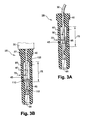
FIGS. 3A-3F illustrate sectional views of alternative embodiments of the present invention;
FIG. 4 is a sectional view of yet another embodiment of the present invention;
FIG. 5 is a perspective view of an outer member structured to encapsulate a portion of a spark plug boot constructing according to the present invention;
FIG. 6 is a sectional view taken along cutting plane 55 of FIG. 5;
FIG. 7 is a perspective view of another embodiment of an encapsulation member structured to enclose a portion of a spark plug boot constructed according to the present invention;
FIG. 8 is a sectional view taken along cutting plane 77 of FIG. 7;
FIG. 9 is an elevation view of an alternative embodiment of an encapsulation member structured to enclose a portion of a spark plug boot constructed according to the present invention; and
FIG. 10 is a flowchart illustrating one method for tuning a capacitor constructed according to the present invention.
It will be recognized that some or all of the Figures are schematic representations for purposes of illustration and do not necessarily depict the actual relative sizes or locations of the elements shown.
DETAILED DESCRIPTION OF THE INVENTION
In the following paragraphs, the present invention will be described in detail by way of example with reference to the attached drawings. Throughout this description, the preferred embodiment and examples shown should be considered as exemplars, rather than as limitations on the present invention. As used herein, “the present invention” refers to any one of the embodiments of the invention described herein.
The purpose of an ignition system is to produce a powerful enough spark to initiate combustion of a fuel-air mixture. Combustion efficiency can be improved by increasing the power of the spark. The present invention increases spark power and intensity by positioning a capacitor between an electrical power supply and the spark plug. An electrical charge delivered from the power supply is stored in the capacitor and then quickly released, greatly increasing the intensity and power of the spark. One embodiment of the capacitor consists of an inner element or inner capacitive member, a dielectric, and a cylinder head that acts as the outer capacitor member. By using the cylinder head as an outer capacitor member, an extremely compact capacitor can be designed and installed in the tight confines of modem-day cylinder heads that position the spark plug at the bottom of a narrow cylinder head cavity. In addition, a capacitor that uses the cylinder head as the outer capacitor member is inexpensive to produce, and can be configured to suit a wide variety of cylinder head designs. Moreover, by using the cylinder head as the outer capacitor member, the capacitor is connected in parallel with the spark plug, as opposed to being connected in series, thereby increasing the capacitor and ignition system efficiency.
Referring to FIG. 1, illustrating one embodiment of the present invention, a capacitive spark plug boot 25 operates like an inner member and insulator of a capacitor with the cylinder head 20 acting as the outer member of a capacitor. The capacitive spark plug boot 25 constructed and optimized according to one method of the present invention provides a way to improve fuel-air combustion. The capacitive spark plug boot 25 may be tuned to suit individual ignition systems to provide current to the spark plug 5 in a manner that creates an increased spark intensity, or power compared to conventional coil-on-plug ignition systems. As defined herein, a capacitive spark plug boot is any device that connects a spark plug to a power source. An ignition wire may be used with a capacitive spark plug boot to connect the boot to a power source. In addition, the present invention provides a method for optimizing spark duration, that is, the amount of time the spark lasts, by adjusting, or tuning the spark plug boot 25.
As defined herein, a capacitor is a device that opposes any change in circuit voltage. In the present invention, a circuit is established between the power source, the spark plug boot 25, the spark plug 5 and an electrical ground. The outer, or ground electrode 15 of the spark plug 5 operates as one ground path, and the cylinder head 20 operates as a second ground path. Alternatively, the ground may be an engine block, vehicle component, or any other suitable electrical ground. Capacitors store electrical energy, and are generally constructed of two electrically conductive members, such as plates, that are isolated from one another by a dielectric material. In the present invention, one electrically conductive member is the inner capacitor member 45 and the second electrically conductive member is the cylinder head 20, which is illustrated in FIGS. 1 and 2. The dielectric member 40 insulates the inner capacitor member 45 from the cylinder head 20.
As shown in FIG. 1, a coil-on-plug or coil-near-plug ignition system arranged to include the present invention comprises, in part, a spark plug 5 mounted in a cylinder head 20, a capacitive spark plug boot 25 and a coil or electrical power source 35. The cylinder head 20 may include engine valve covers, and may also include one or more recesses or channels 22 formed in the cylinder head 20 to adjust the contact area between the dielectric member 40 and the cylinder head 20.
The present invention can also be incorporated into a conventional single-coil, or distributed ignition system where one coil sends electrical energy to a distributor that distributes the energy among a group of ignition wires. With a single-coil system, a capacitive spark plug boot 25 would be coupled to the end of each ignition wire, thereby electrically connecting the spark plug 5 to the ignition wire.
For example, the spark plug boot 25 couples the spark plug 5 to the coil, or power source 35. In a “coil-near-plug” system, a short ignition wire 30 may connect the power source 35 to the spark plug boot 25. Preferably, the power source 35 is a coil, but other devices, such as a magneto, that provide electrical energy can be used with the present invention. Preferably, the power source 35 is an ignition coil that amplifies 12 volts (V) received from a battery to approximately 20,000 V. Alternative batteries can supply 6, 24, 36 or 42 volts to the power source 35. Moreover, power source voltages can range from 5,000 V to 80,000 V, or more, depending upon the ignition system requirements.
Referring to FIG. 2, the spark plug boot 25 includes an inner capacitor member 45 surrounded by a dielectric member 40. The dielectric member 40 may be constructed of rubber, silicone or other suitable electrically insulating materials. One embodiment dielectric is a high-purity silicone dielectric known as SILCOSET (SILCOSET is a trademark of Imperial Chemical Industries, Ltd. of London, England), having a dielectric constant of about 20×106 volts per meter and a permittivity of about 3.4. If a different dielectric material is employed, having a different dielectric constant and permittivity, the thickness of the dielectric would have to be changed to maintain a similar electric insulation value. For example, the dielectric thickness 70 can vary from about 1 millimeter to about 10 millimeters, depending on the type of dielectric employed.
In one embodiment, the inner capacitor member 45 is located between an ignition cable terminal 50 and a spark plug terminal 55. The inner capacitor member 45 must be constructed of a conductive material. Any conductive material can be used to form the inner capacitor member 45, such as aluminum, steel, silver, copper or other suitable conductive materials. As illustrated in FIGS. 2-4, the inner capacitor 45 can assume several different shapes including, but not limited to a cylinder, helix, spiral and other shapes designed to suit individual ignition system requirements. Also, as illustrated in FIG. 4, the inner capacitor 45 can include holes 85, cavities, slots 90, channels, slits and other features that change the shape and surface area of inner capacitor 45. As discussed in detail below, the capacitance of a capacitor can be varied in several ways including: adjusting the inner capacitor member diameter 65, the inner capacitor member height 75, and the inner capacitor member thickness 80. One aspect of the present invention involves adjusting the components of the spark plug boot 25 so that the capacitor has a specific capacitance. This “tuning” of the capacitor ensures that an ideal capacitor is constructed for each individual ignition system.
Referring to FIG. 3A an alternative embodiment capacitive spark plug boot 25 is illustrated. This capacitive spark plug boot 25 is structured to receive a standard ignition wire 30 that may be used in a coil-near-plug ignition system or in a “coil-pack” system. A connector 95 connects the ignition wire 30 to the inner capacitor member 45. A spark plug terminal 55 connects the ignition wire 30 to the spark plug 5. This embodiment uses a cylindrical sheet of copper as the inner capacitor member 45, but as discussed above other conductive materials can be employed.
Referring now to FIG. 3B, another embodiment capacitive spark plug boot 25 is illustrated. This capacitive spark plug boot 25 includes a coil connector 100 and a coil aperture 105 that receives a coil spring or other type of connector 37 from a coil-on-plug coil. The coil connector 37 may be a wire, spring or other device designed to transmit the voltage generated by the coil 35 to the inner capacitor member 45. Positioned between the coil aperture 105 and the inner capacitor member is a resistor 110. As discussed in detail below, the resistor 110 minimizes electromagnetic interference generated by the spark plug 5 spark. A spark duration resistor 112 may be positioned next to the spark plug terminal to adjust the duration of the spark plug 5 spark. The resistance of the resistor 110 can range between about 1000 ohms to about 3000 ohms. The resistance of the spark duration resistor 112 can range between about 50 ohms to about 1000 ohms.
Illustrated in FIG. 3C, is yet another embodiment of a capacitive spark plug boot 25. This capacitive spark plug boot 25 includes a resistive inductor 115 that functions in a similar manner to the resistor 110 illustrated in FIG. 3B. A spark duration resistor 112 is located at the end of the inner capacitor member 45.
Referring to FIG. 3D a capacitive spark plug boot 25 structured to receive an ignition coil wire 30 is illustrated. Similar to the embodiment illustrated in FIG. 3A, this capacitive spark plug boot 25 is structured to receive an ignition wire 30 from a coil-near-plug, or distributive, ignition system. Similar to the embodiments illustrated in FIGS. 3A-3C, the inner capacitor member 45 is substantially cylindrical with a dielectric member 40 surrounding the inner capacitor member 45.
Referring to FIG. 3E, an alternative embodiment capacitive spark plug boot 25 is illustrated. The inner capacitor member 45 comprises a spiral, or helical wound structure 120. The helix is bendable and increases the overall flexibility of the spark plug boot 25. Illustrated in FIG. 3F, is an alternative embodiment capacitive spark plug boot 25 that incorporates a mesh-type structure 125 for the inner capacitor member 45. Similar to the embodiment of FIG. 3E, the mesh increases the flexibility of the spark plug boot 25. Alternatively, the inner capacitor member may be constructed of a conductive material in a foil-type form that is also flexible. Flexibility of the spark plug boot 25 can be advantageous in applications that require bending of the spark plug boot 25.
Referring to FIG. 5, an outer member or sleeve 500 is illustrated. The sleeve 500 is sized to receive any one of the capacitive spark plug boots 25 described above. Specifically, the inner diameter of the sleeve 500 is sized to closely engage the outer surface of the dielectric member 40. Once the capacitive spark plug boot 25 is positioned within the sleeve 500, the sleeve is then inserted into the cylinder head 20. The outer surface of the sleeve 500 is structured to slidingly engage the cylinder head 20 establishing an electrical contact so that the cylinder head 20 can function as a second electrical ground path. Illustrated in FIGS. 5 and 6, a plurality of channels 505 are longitudinally positioned along the outer surface of the sleeve 500. The channels 505 permit the sleeve 500 to deflect as it is inserted into the cylinder head 20. The sleeve 500 has a maximum diameter 510 at the approximate midpoint of the sleeve 500. As the sleeve 500 is inserted into the cylinder head 20, the channels 505 will compress decreasing the diameter 510 of the sleeve, ensuring an interference fit with the cylinder head 20.
Referring to FIG. 7, an alternative embodiment sleeve 700 is illustrated. Sleeve 700 includes two substantially half-cylindrical sections 705 that are deflectably mounted to a inner cylinder 710. As illustrated in FIGS. 7 and 8, the half-cylinder sections 705 each have a fixed edge 715 and a free edge 720. Each fixed edge 715 is connected to the inner cylinder 710. Illustrated in FIG. 8, the free edge 720 of each half-cylinder section 705 can slide along an outer surface of the inner cylinder 710. The outer surface of the half-cylinder sections 705 slidingly engage the cylinder head 20 and can deflect to adapt to different sized cylinder heads 20. As discussed above in connection with sleeve 500, the alternative sleeve 700 is configured to receive any one of the capacitive spark plug boots 25 described above.
Referring to FIG. 9, another embodiment sleeve 900 is illustrated. The sleeve 900 is configured to receive a spark plug boot 25 and includes deflectable ribs 905 attached to an outer surface of the sleeve 900. The deflectable ribs 905 engage the cylinder head 20 when the sleeve 900 is inserted into the cylinder head 20. As discussed above in connection with the sleeve 500, alternative sleeve 900 is structured to receive a capacitive spark plug boot 25 and establish an electrical connection with the cylinder head 20. The present invention may incorporate individual features from any one of the herein disclosed embodiments.
In another aspect of the present invention, the capacitive spark plug boot 25 is electrically connected in parallel with the spark plug 5. Electrical devices can either be connected in parallel or in series. As shown in FIG. 1, the spark plug 5 is connected to an electrical ground through the ground electrode 15. The capacitive spark plug boot 25, employing the cylinder head 20 as an outer capacitor member, is connected to an electrical ground though the cylinder head 20. Therefore, the spark plug 5 and the capacitive spark plug boot 25 use different electrical paths to ground thereby connecting the components in parallel. In contrast, other capacitive devices are connected in series.
One theory of the operation of a capacitive spark plug boot 25 constructed according to the present invention is that when current is sent from the power source 35 to the inner capacitor member 45, the current is attracted to the electrical ground of the cylinder head 20. The cylinder head 20 and inner capacitor member 45 become capacitor electrodes separated by the dielectric member 40. The capacitor electrodes store the energy sent by the power source 35 until their capacity is reached. A final amount of energy sent by the power source 35 passes through the inner capacitor member 45 and generates sufficient voltage between spark plug electrodes 10 and 15 to create a spark. The capacitor then discharges, sending all of its stored energy to the spark plug 5 in a burst, creating a powerful spark.
The present invention consists of a surface-area-sizeable inner capacitor member 45 and a distance-sizeable dielectric member 40 that uses the cylinder head 20 as the outer capacitor member. In a preferred embodiment of the present invention, the capacitor is constructed to suit individual ignition systems. This is in contrast to conventional devices, that are constructed using a capacitive one-size-fits-all mentality. These devices either have too great, or too small a capacitance. For example, a device with high capacitance, but without sufficient resistance will deliver the stored capacitor energy in too short a time, creating a spark duration so short that ignition of the fuel-air mixture is erratic, or non-existent. Alternatively, when the capacitance of the device is too small, generally because the capacitor's size is limited by space constraints, there is no improvement in ignition of the fuel-air mixture.
A conventional coil-on-plug ignition system delivers the coil energy to the spark plug. However, the coil cannot deliver all required energy in a short burst, but instead requires time to discharge the energy. This creates a spark duration or time that is too long—between about two to four thousands of a second (0.002-0.004 sec). A long spark duration decreases spark power, because Power=Work/time. Therefore, by decreasing spark duration, spark power can be increased. Increased spark power improves the performance of modern-day engines that use lean fuel-air mixtures and have high combustion chamber temperatures and pressures.
A capacitive spark plug boot 25 configured according to the method of the present invention has a spark duration in the range of about 40 to 1000 nanoseconds. Therefore, spark power is significantly increased, and complete combustion, even under unfavorable conditions is assured. In addition, the capacitive spark plug boot 25 is carefully sized, or tuned to the power source 35 so that the capacitor is fully charged, yet sufficient energy is generated at the center electrode 10 to create a spark. Also, as illustrated in FIGS. 3B and 3C, a spark duration resistor 112 is optimized so that spark duration can be adjusted to initiate combustion. A capacitive spark plug boot 25 that performs as described above must be carefully tuned and constructed.
FIG. 10 depicts a method for tuning a capacitive spark plug boot 25 having an optimal capacitance value. The method of the present invention can be used to construct a capacitive spark plug boot 25 that can be used on any device requiring spark ignition of a flammable fuel, such as 2-stroke engines, 4-stroke engines, Wankel engines, Miller-cycle engines and other fuel burning devices.
The first step 200 is to determine the available current. This is accomplished by inspecting the power source 35 to determine its output. A conventional power source 35 employs an ignition coil that amplifies 12 volts (V) received from a conventional battery to approximately 20,000 V. Alternative power sources 35 can supply 6, 24, 36 or 42 volts to the ignition coil. Moreover, voltages can range from 5,000 V to 80,000 V, or more, depending upon the coil characteristics.
The next step 205 is to select an optimal capacitance value. The capacitor must be sized so that it becomes fully charged, yet it must also allow passage of sufficient energy or current to create a spark at the spark plug. If the capacitance of the capacitor is too large, a spark will not form and combustion of the fuel-air mixture will not occur. Conversely, if the capacitance of the capacitor is too small, spark intensity will not increase enough to improve ignition of the fuel-air mixture. A capacitor having an optimal capacitance value is determined by finding a maximum capacitance value and subtracting a safety margin.
The capacitance value of the capacitive spark plug boot 25 may be increased as the voltage output of the coil increases. The optimal capacitance value for each ignition system is determined by finding the maximum capacitance value and subtracting a safety margin. The maximum capacitance value is the capacitance value of the capacitive spark plug boot 25 that causes intermittent, sporadic or no spark at the spark plug 5. In contrast, a consistent spark is a spark that occurs substantially every time at the spark plug 5.
To make certain that a spark is developed at the spark plug 5 under virtually all conditions, a small safety margin is subtracted from a maximum capacitance value to arrive at an optimal capacitance value. A capacitance decrease of about 10 to 15 picofarads has been found to be a sufficient safety margin. This allows for manufacturer variations, power source deterioration, transient ignition system conditions and other effects.
Once the small safety margin has been subtracted from the maximum capacitance value, the optimal capacitance value is found. For example, if the maximum capacitance value is 40 picofarads, a safety margin of about 10 picofarads would be subtracted leaving an optimal capacitance value of about 30 picofarads.
Therefore, the optimal capacitance value for a specific ignition system can be determined and a capacitive spark plug boot 25 can be constructed accordingly. The method of constructing a capacitive spark plug boot 25 according to the present invention allows for the optimum spark to be developed by tuning the capacitive spark plug boot 25 to suit the requirements of individual ignition systems.
As shown in FIG. 10, the next step 210 in tuning the capacitive spark plug boot 25 is to adjust the capacitance of the capacitor so that it matches the optimal capacitance value. Generally, there are three ways to adjust the capacitance of a capacitor: 1) the area of the inner capacitor member 45 and the outer capacitor member, in this case the cylinder head 20, can be changed; 2) the distance between the inner capacitor member 45 and the cylinder head 20 can be changed; and 3) the material used for the dielectric member 40 can be changed. If necessary, the cylinder head 20 may be modified to include a recess or slot 22 to change the surface area that contacts the dielectric member 40, as shown in FIG. 1.
Referring to FIG. 4, a capacitive spark plug boot 25 is illustrated and depicts several methods used to change the area of the inner capacitor member 45. Because the area of the outer capacitor member, which is the cylinder head 20, cannot be changed easily, a capacitance formula has been developed to determine capacitance based on the area of the inner capacitor member 45 and the thickness of the dielectric member 40. The capacitance of the capacitive spark plug boot 25 can be determined by the following capacitance formula (1): C = ɛ A P T D ( 1 )
Figure US06374816-20020423-M00001
where C is the capacitance of the capacitive spark plug boot 25, ∈ is the permittivity constant of 37.0×10⁻¹² farads per meter, Ap is the area of the inner capacitor member 45, and TD is the dielectric member thickness 70. A preferred embodiment capacitive spark plug boot 25 may employ a substantially cylindrical inner capacitor member 45 and therefore the area Ap of the inner capacitor member 45 is determined by the following equation (2):
AP=πDcLc  (2)
where Dc is the inner capacitor member diameter 65, and Lc is the inner capacitor member length 75, illustrated in FIG. 4. Therefore, the capacitance of the capacitive spark plug boot 25 illustrated in FIG. 4 is equal to the following equation (3): C = ɛ π Dc Lc T D ( 3 )
Figure US06374816-20020423-M00002
By changing the dimensions or values of each of the equation elements, the capacitance of the capacitive spark plug boot 25 can be optimized to suit specific ignition systems. Illustrated in FIG. 4, the area of the inner capacitor member 45 can be adjusted to suit specific ignition system requirements by also including one or more holes 85 or slots 90 in the inner capacitor member 45. By removing material from the inner capacitor member 45, the area of the inner capacitor member 45 is decreased, lowering the capacitance of the capacitive spark plug boot 25. As shown in FIGS. 3A-E, the inner capacitor member 45 can be constructed in a number of different ways to arrive at an optimal area Ap that creates an optimum capacitance.
As discussed above, another method of sizing, or tuning the capacitor is to increase or decrease the distance between the inner capacitor member 45 and the cylinder head 20. This is accomplished by changing the dielectric member thickness 70. The distance between capacitor elements of a capacitor effects the charge that is stored on each element. Capacitance increases when the capacitor elements are brought together. The thinner the dielectric, the closer the plates will be. A thin dielectric can thus increase capacitance. The dielectric member thickness 70 can vary from about 1 millimeter to over 10 millimeters, depending upon the requirements of individual ignition systems. The material used in a preferred embodiment dielectric member has an dielectric constant of about 15.8×10⁶ volts per meter. If a dielectric having a different dielectric constant is used, the dielectric member thickness 70 would change to maintain the same electrical insulation value.
As shown in FIG. 10, once the capacitor has been optimally sized, the next step 215 in tuning the capacitive spark plug boot 25 is to determine the ideal spark duration, or time. A long spark duration decreases spark power, because Power=Work/time (or, electrically, Power=current×voltage). Current=charge/time, or put differently, current is the rate of flow of charge. Therefore, it follows that if the same amount of charge is delivered in less time, that is, if spark duration is decreased, spark power will be increased. A capacitive spark plug boot 25 constructed according to the present invention receives the same amount of electrical energy from the power source 35 as a conventional spark plug cable. However, since the present invention greatly reduces the spark duration, the spark power is proportionally increased. This greatly increases the spark intensity, creating a hotter spark thereby producing more efficient combustion.
Conventional ignition systems have a spark duration that is too long—between about two to four thousands of a second (0.002-0.004 sec). A capacitive spark plug boot 25 configured according to one method of the present invention has a spark duration in the range of 40 to 1000 nanoseconds depending on the ignition system and combustion chamber characteristics.
Referring again to FIG. 10, once the correct spark duration is determined, the next step 220 in tuning the capacitive spark plug boot 25 is to select an ideal resistance. One unique aspect of one method of the present invention is to optimize, or tune the spark duration by adjusting the resistance of spark duration resistor 112. Greater resistance increases spark duration and conversely, less resistance decreases spark duration. A preferred embodiment capacitive spark plug boot 25 will have a spark duration of about 300 nanoseconds. However, depending upon the design of the ignition system, and the requirements of the engine, spark duration may range from about 40 to about 1000 nanoseconds. The ideal resistance is selected by determining the capacitance of the capacitor, determining the capacitor's discharge characteristics, and determining the resistance between the capacitor and the spark plug 5, as all of these factors affect spark duration.
Shown in FIG. 10, the next step 225 is to adjust the resistance of capacitive spark plug boot 25 to approximate the ideal resistance. This is accomplished by selecting or constructing a spark duration resistor 112 that has an appropriate resistance. The resistance of the spark duration resistor 112 may range between about 50 ohms to about 1000 ohms. An alternative method is to increase the length of the inner capacitor member 45, thereby increasing the resistance of the capacitive spark plug boot 25.
Another advantage of the capacitive spark plug boot 25 is that electromagnetic interference (EMI) generated by the electrical energy sent to the spark plug 5 is minimized by employing the resistor 110 or the resistive inductor 115. The EMI can be in the form of unwanted high-frequency electrical signals also known as radio-frequency interference (RFI). Modem engine electronics, such as computer controlled, OBD II equipped engine management systems are extremely sensitive to EMI. Some ignition systems employing high-voltage power sources 35 can produce excessive, and damaging, amounts of EMI.
Thus, it is seen that an apparatus and method for combustion initiation, such as a capacitive spark plug boot, is provided. One skilled in the art will appreciate that the present invention can be practiced by other than the preferred embodiments, which are presented in this description for purposes of illustration and not of limitation, and the present invention is limited only by the claims that follow. It is noted that various equivalents for the particular embodiments discussed in this description may practice the invention as well.

Claims (41)

What is claimed is:
1. A capacitor for an ignition system comprising an electrical current source and a spark plug mounted in a cylinder head, the capacitor comprising:
a center element structured to carry electric current from the electrical current source to the spark plug; and
an insulator surrounding the center element, an outer surface of the insulator sized to engage the cylinder head;
wherein the center element, the insulator and the cylinder head comprise a capacitor.
2. The capacitor of claim 1, further including a outer member positioned about the insulator, the outer member structured to slidably engage the cylinder head.
3. The capacitor of claim 2, wherein the outer member comprises a cylinder with an inner surface engaging the insulator, and a deflectable rib attached to an outer surface of the cylinder, the deflectable rib structured to slidably engage the cylinder head.
4. The capacitor of claim 2, wherein the outer member comprises a cylinder including two substantially half-cylinder sections, each section having two edges, with one section edge attached to the cylinder so that the half-cylinder sections are deflectably attached to the cylinder and can thereby deflectably engage the cylinder head.
5. The capacitor of claim 2, wherein the outer member comprises a cylinder including two substantially half-cylinder members attached to the cylinder, the half-cylinder members having a maximum diameter near a middle of the cylinder, with the diameter decreasing toward each end of the cylinder, the half-cylinder members including a longitudinal slot so that the half-cylinder members can deflectably engage the cylinder head.
6. The capacitor of claim 2, wherein the outer member is comprised of a material selected from the group consisting of: conductive materials; ferromagnetic materials; copper; tin; brass and steel; and a combination of any one of copper, tin, brass and steel.
7. The capacitor of claim 1, wherein the center element comprises a first capacitor member, and a capacitance of the capacitor is adjusted by selectively increasing and decreasing a surface area of the center element.
8. The capacitor of claim 1, wherein a capacitance of the capacitor is adjusted by selectively increasing and decreasing a distance from the center element to a cylinder head surface.
9. The capacitor of claim 1, wherein the center element includes features selected from the group consisting of: holes, slots, cavities, voids, dimples, and indentations.
10. The capacitor of claim 1, wherein the center element comprises a first capacitor member selected from the group consisting of: a rolled strip, a helix-wound strip, a foil, a wire mesh, a spring, a stamped element, a cast element and a machined element.
11. The capacitor of claim 1, further including an ignition cable connector arranged to electrically connect the electrical current source to the center element, and a spark plug connector arranged to electrically connect the center element to the spark plug.
12. The capacitor of claim 1, further including a spark duration adjusting element communicating with the center element, the spark duration adjusting element comprising a resistor.
13. The capacitor of claim 1, further including an electromagnetic interference suppressing element communicating with the center element, the electromagnetic interference suppressing element selected from the group consisting of resistors and resistive inductors.
14. The capacitor of claim 1, wherein the center element and insulator are sized and configured to produce an optimum capacitance value, the optimum capacitance value determined by finding a maximum capacitance value and subtracting a safety margin;
wherein the maximum capacitance value is determined when the spark plug sparks sporadically and the safety margin is determined when the spark plug sparks consistently.
15. The capacitor of claim 14, wherein the optimum capacitance value can range from about 10 picofarads to about 200 picofarads.
16. The capacitor of claim 1, wherein the cylinder head includes valve covers.
17. A spark plug boot for a coil-on-plug ignition system comprising an electrical current source and a spark plug mounted in a cylinder head, the spark plug boot comprising:
a center element structured to carry electric current from the electrical current source to the spark plug, the spark plug comprising a first electrical path to ground; and
an insulator surrounding the center element, an outer surface of the insulator sized to engage the cylinder head;
wherein the center element, the insulator and the cylinder head comprise a capacitor, the capacitor having a second electrical path to ground, so that the spark plug and the capacitor are electrically connected in parallel.
18. The spark plug boot of claim 17, wherein the cylinder head comprises a cylinder head cavity, with the outer surface of the insulator sized to engage the cylinder head cavity, and the second electrical path to ground for the capacitor is a surface of the cylinder head cavity.
19. The spark plug boot of claim 17, further including a outer member positioned about the spark plug boot, the outer member structured to slidably engage the cylinder head thereby providing the second electrical path to ground.
20. The spark plug boot of claim 19, wherein the outer member is selected from a group consisting of:
a cylinder with an inner surface engaging the spark plug boot, and a deflectable rib attached to an outer surface of the cylinder, the deflectable rib structured to slidably engage the cylinder head;
a cylinder including two substantially half-cylinder sections, each section having two edges, with one section edge attached to the cylinder so that the half-cylinder sections are deflectably attached to the cylinder and can thereby deflectably engage the cylinder head; and
a cylinder including two substantially half-cylinder members attached to the cylinder, the half-cylinder members having a maximum diameter near a middle of the cylinder, with the diameter decreasing toward each end of the cylinder, the half-cylinder members including a longitudinal slot so that the half-cylinder members can deflectably engage the cylinder head.
21. The spark plug boot of claim 17, wherein the center element comprises a first capacitor member, and a capacitance of the capacitor is adjusted by selectively increasing and decreasing a surface area of the center element.
22. The spark plug boot of claim 17, wherein the center element includes features selected from the group consisting of: holes, slots, cavities, voids, dimples and indentations.
23. The spark plug boot of claim 17, wherein the center element comprises a first capacitor member selected from the group consisting of: a rolled strip, a helix-wound strip, a foil, a wire mesh, a spring, a stamped element, a cast element, and a machined element.
24. The spark plug boot of claim 17, further including a spark duration adjusting element communicating with the center element, the spark duration adjusting element comprising a resistor.
25. The spark plug boot of claim 17, further including an electromagnetic interference suppressing element communicating with the center element, the electromagnetic interference suppressing element selected from the group consisting of resistors and resistive inductors.
26. The spark plug boot of claim 17, wherein the center element and insulator are sized and configured to produce an optimum capacitance value, the optimum capacitance value determined by finding a maximum capacitance value and subtracting a safety margin;
wherein the maximum capacitance value is determined when the spark plug sparks sporadically and the safety margin is determined when the spark plug sparks consistently.
27. The spark plug boot of claim 26, wherein the optimum capacitance value can range from about 10 picofarads to about 200 picofarads.
28. A spark plug boot configured to individual coil-on-plug ignition systems, each ignition system comprising an electrical current source and a spark plug mounted in a cylinder head cavity, the spark plug boot comprising:
a center element structured to carry electric current from the electrical current source to the spark plug; and
an insulator surrounding the center element, an outer surface of the insulator sized to engage a surface of the cylinder head cavity;
wherein the center element, the insulator and the cylinder head comprise a capacitor that has a capacitance which is optimized for each coil-on-plug ignition system.
29. The spark plug boot of claim 28, wherein the capacitance of the capacitor is optimized by finding a maximum capacitance value and subtracting a safety margin;
with the maximum capacitance value determined when the spark plug does not spark consistently; and
the safety margin is determined when the spark plug sparks consistently.
30. The spark plug boot of claim 29, wherein the center element comprises a first capacitor member, and a capacitance of the capacitor is adjusted by selectively increasing and decreasing a surface area of the center element.
31. The spark plug boot of claim 29, wherein the center element comprises a first capacitor member, and a capacitance of the capacitor is adjusted by selectively increasing and decreasing a distance from the center element to a cylinder head surface.
32. The spark plug boot of claim 29, further including a outer member positioned about the spark plug boot, the outer member structured to deflectably engage the cylinder head.
33. The spark plug boot of claim 32, wherein the outer member is selected from a group consisting of:
a cylinder with an inner surface engaging the spark plug boot, and a deflectable rib attached to an outer surface of the cylinder, the deflectable rib structured to slidably engage the cylinder head;
a cylinder including two substantially half-cylinder sections, each section having two edges, with one section edge attached to the cylinder so that the half-cylinder sections are deflectably attached to the cylinder and can thereby deflectably engage the cylinder head; and
a cylinder including two substantially half-cylinder members attached to the cylinder, the half-cylinder members having a maximum diameter near a middle of the cylinder, with the diameter decreasing toward each end of the cylinder, the half-cylinder members including a longitudinal slot so that the half-cylinder members can deflectably engage the cylinder head.
34. The spark plug boot of claim 29, further including a spark duration adjusting element communicating with the center element, the spark duration adjusting element comprising a resistor.
35. The spark plug boot of claim 29, further including an electromagnetic interference suppressing element communicating with the center element, the electromagnetic interference suppressing element selected from the group consisting of resistors and resistive inductors.
36. A method for optimizing a storage capacity of a capacitor included within a coil-on-plug ignition system, the method comprising the steps of:
providing a capacitor, the capacitor comprising a center element, an insulator surrounding the center element, the outer surface of the insulator sized to engage a cylinder head, with the center element, the insulator and the cylinder head comprising the capacitor;
determining an available electric current from the coil-on-plug ignition system communicating with the capacitor;
selecting an optimum capacitance value for the coil-on-plug ignition system by finding a maximum capacitance value and subtracting a safety margin; and
adjusting a capacitance of the capacitor to approximate the optimum capacitance value.
37. The method of claim 36, wherein the maximum capacitance value is determined when the spark plug does not spark consistently and the safety margin is determined when the spark plug sparks consistently.
38. The method of claim 36, wherein the optimum capacitance value can range from about 10 picofarads to about 200 picofarads.
39. The method of claim 36, wherein the step of adjusting the capacitance of the capacitor is accomplished by selectively increasing and decreasing a distance between the center element and the cylinder head.
40. The method of claim 36, further including the step of suppressing electromagnetic interference by providing at least one of a resistor and a resistive inductor that communicate with the center element.
41. A spark plug boot for a coil-on-plug ignition system comprising an electrical current source and a spark plug mounted in a cylinder head cavity, the spark plug boot comprising:
a center element structured to carry electric current from the electrical current source to the spark plug; and
an insulator surrounding the center element; and
an outer member positioned about at least a portion of the insulator, the outer member sized to engage the cylinder head cavity, the outer member selected from the group consisting of:
a cylinder with an inner surface engaging the spark plug boot, and a deflectable rib attached to an outer surface of the cylinder, the deflectable rib structured to slidably engage the cylinder head;
a cylinder including two substantially half-cylinder sections, each section having two edges, with one section edge attached to the cylinder so that the half-cylinder sections are deflectably attached to the cylinder and can thereby deflectably engage the cylinder head; and
a cylinder including two substantially half-cylinder members attached to the cylinder, the half-cylinder members having a maximum diameter near a middle of the cylinder, with the diameter decreasing toward each end of the cylinder, the half-cylinder members including a longitudinal slot so that the half-cylinder members can deflectably engage the cylinder head;
wherein the center element, the insulator and the outer member comprise a capacitor.
US09/840,313 2001-04-23 2001-04-23 Apparatus and method for combustion initiation Expired - Lifetime US6374816B1 (en)

Priority Applications (3)

Application Number Priority Date Filing Date Title
US09/840,313 US6374816B1 (en) 2001-04-23 2001-04-23 Apparatus and method for combustion initiation
US10/116,199 US6615810B2 (en) 2001-04-23 2002-04-03 Apparatus and method for combustion initiation
PCT/US2002/012877 WO2002086311A1 (en) 2001-04-23 2002-04-22 Combustion initiation apparatus and method

Applications Claiming Priority (1)

Application Number Priority Date Filing Date Title
US09/840,313 US6374816B1 (en) 2001-04-23 2001-04-23 Apparatus and method for combustion initiation

Related Child Applications (1)

Application Number Title Priority Date Filing Date
US10/116,199 Continuation-In-Part US6615810B2 (en) 2001-04-23 2002-04-03 Apparatus and method for combustion initiation

Publications (1)

Publication Number Publication Date
US6374816B1 true US6374816B1 (en) 2002-04-23

Family

ID=25282003

Family Applications (2)

Application Number Title Priority Date Filing Date
US09/840,313 Expired - Lifetime US6374816B1 (en) 2001-04-23 2001-04-23 Apparatus and method for combustion initiation
US10/116,199 Expired - Lifetime US6615810B2 (en) 2001-04-23 2002-04-03 Apparatus and method for combustion initiation

Family Applications After (1)

Application Number Title Priority Date Filing Date
US10/116,199 Expired - Lifetime US6615810B2 (en) 2001-04-23 2002-04-03 Apparatus and method for combustion initiation

Country Status (2)

Country Link
US (2) US6374816B1 (en)
WO (1) WO2002086311A1 (en)

Cited By (9)

* Cited by examiner, † Cited by third party
Publication number Priority date Publication date Assignee Title
US6736119B1 (en) * 2003-01-29 2004-05-18 Harvey G. Kiker Ignition spark enhancing device
US20040194768A1 (en) * 2003-01-29 2004-10-07 Kiker Harvey G. Ignition spark enhancing device
US20050161031A1 (en) * 2002-02-08 2005-07-28 Johnson Controls Automotive Electronics Electronic module for internal combustion engine ignition coil
US20050199411A1 (en) * 2004-03-12 2005-09-15 Doll Martin J. Method and apparatus for interconnecting a coil and a spark plug
US20060089024A1 (en) * 2004-10-22 2006-04-27 Markus Kraus Spark plug connector
US20070272189A1 (en) * 2006-05-26 2007-11-29 Kiker Harvey G D.c. power enhancer for battery-powered vehicles and internal combustion engines
US20070293064A1 (en) * 2006-06-16 2007-12-20 Dennis Steinhardt Spark plug boot
US20080271723A1 (en) * 2006-05-17 2008-11-06 Cowden Ralph A Anti global warming energy power system and method
US8638540B2 (en) 2010-12-15 2014-01-28 Federal-Mogul Ignition Company Corona igniter including ignition coil with improved isolation

Families Citing this family (19)

* Cited by examiner, † Cited by third party
Publication number Priority date Publication date Assignee Title
US8225768B2 (en) 2008-01-07 2012-07-24 Mcalister Technologies, Llc Integrated fuel injector igniters suitable for large engine applications and associated methods of use and manufacture
WO2011034655A2 (en) 2009-08-27 2011-03-24 Mcalister Technologies, Llc Ceramic insulator and methods of use and manufacture thereof
US7628137B1 (en) 2008-01-07 2009-12-08 Mcalister Roy E Multifuel storage, metering and ignition system
US8413634B2 (en) 2008-01-07 2013-04-09 Mcalister Technologies, Llc Integrated fuel injector igniters with conductive cable assemblies
US8387599B2 (en) 2008-01-07 2013-03-05 Mcalister Technologies, Llc Methods and systems for reducing the formation of oxides of nitrogen during combustion in engines
US8635985B2 (en) 2008-01-07 2014-01-28 Mcalister Technologies, Llc Integrated fuel injectors and igniters and associated methods of use and manufacture
US8074625B2 (en) 2008-01-07 2011-12-13 Mcalister Technologies, Llc Fuel injector actuator assemblies and associated methods of use and manufacture
US8365700B2 (en) 2008-01-07 2013-02-05 Mcalister Technologies, Llc Shaping a fuel charge in a combustion chamber with multiple drivers and/or ionization control
US8561598B2 (en) 2008-01-07 2013-10-22 Mcalister Technologies, Llc Method and system of thermochemical regeneration to provide oxygenated fuel, for example, with fuel-cooled fuel injectors
JP5718921B2 (en) 2009-08-27 2015-05-13 マクアリスター テクノロジーズ エルエルシー Configuration of fuel charge in a combustion chamber with multiple drivers and / or ionization control
SG181518A1 (en) 2009-12-07 2012-07-30 Mcalister Technologies Llc Adaptive control system for fuel injectors and igniters
US20110297753A1 (en) 2010-12-06 2011-12-08 Mcalister Roy E Integrated fuel injector igniters configured to inject multiple fuels and/or coolants and associated methods of use and manufacture
CN102906413B (en) 2010-02-13 2014-09-10 麦卡利斯特技术有限责任公司 Fuel injector assemblies having acoustical force modifiers and associated methods of use and manufacture
WO2011100717A2 (en) 2010-02-13 2011-08-18 Mcalister Roy E Methods and systems for adaptively cooling combustion chambers in engines
US8528519B2 (en) 2010-10-27 2013-09-10 Mcalister Technologies, Llc Integrated fuel injector igniters suitable for large engine applications and associated methods of use and manufacture
US8091528B2 (en) 2010-12-06 2012-01-10 Mcalister Technologies, Llc Integrated fuel injector igniters having force generating assemblies for injecting and igniting fuel and associated methods of use and manufacture
WO2012112615A1 (en) 2011-02-14 2012-08-23 Mcalister Technologies, Llc Torque multiplier engines
CN103890343B (en) 2011-08-12 2015-07-15 麦卡利斯特技术有限责任公司 Systems and methods for improved engine cooling and energy generation
US8919377B2 (en) 2011-08-12 2014-12-30 Mcalister Technologies, Llc Acoustically actuated flow valve assembly including a plurality of reed valves

Citations (41)

* Cited by examiner, † Cited by third party
Publication number Priority date Publication date Assignee Title
US1447812A (en) 1921-05-17 1923-03-06 George T W Otto Spark-plug attachment
US1756486A (en) 1928-11-07 1930-04-29 Cashly A Henry Electric condenser for high-tension ignition circuits
US1902541A (en) 1933-03-21 Method and apbabattts fob igniting combustible mixttlbbs
US2129472A (en) 1934-11-24 1938-09-06 Milo Ab Ignition system
US2173766A (en) 1937-01-20 1939-09-19 Napler & Son Ltd D Electrical ignition apparatus for internal combustion engines
US2376362A (en) 1945-05-22 Ignition system
US2378893A (en) 1942-03-10 1945-06-26 Westinghouse Electric Corp Ignition system
US2392171A (en) * 1943-01-01 1946-01-01 Gen Electric Ignition unit
US2415138A (en) 1942-04-02 1947-02-04 Armen A Kasarjian Spark plug
US2467534A (en) * 1946-11-09 1949-04-19 American Bosch Corp Ignition unit
US2640174A (en) 1950-10-30 1953-05-26 Gen Motors Corp Intensifier
US2904723A (en) 1954-10-30 1959-09-15 Altrogge Ignition contrivance for combustion engines
US2927248A (en) 1957-12-12 1960-03-01 Napier & Son Ltd Spark producing apparatus and adaptors therefor
US3045148A (en) 1962-07-17 Ignition system with transistor control
US3324347A (en) 1964-07-20 1967-06-06 Brugnola Anthony Multiple electrode spark gaps with a condenser connected in parallel with one spark gap
US3336506A (en) 1964-02-24 1967-08-15 Frank Edgar Electric ignition device for oils and gases
US3361932A (en) 1963-05-01 1968-01-02 Rotax Ltd A.c. operated spark ignition apparatus with compensation for changes in the frequency of the a.c. source
US3683232A (en) 1970-02-03 1972-08-08 Baur Elektronik Gmbh Fa Sparkplug cap
US3842819A (en) 1971-11-16 1974-10-22 Ass Eng Ltd Ignition devices
US4082980A (en) 1975-02-13 1978-04-04 Murata Manufacturing Co., Ltd. Spark plug cap providing a capacitor in parallel with the spark cap
US4122816A (en) 1976-04-01 1978-10-31 The United States Of America As Represented By The Administrator Of The National Aeronautics And Space Administration Plasma igniter for internal combustion engine
US4123688A (en) 1975-02-13 1978-10-31 Murata Manufacturing Co., Ltd. Spark plug cap
US4223656A (en) 1978-10-27 1980-09-23 Motorola, Inc. High energy spark ignition system
US4324219A (en) 1979-02-16 1982-04-13 Hayashi Seiko Kabushiki Kaisha Spark intensifier in gasoline engine
US4333125A (en) 1980-02-08 1982-06-01 Hensley George H Combustion initiation system
US4333126A (en) 1980-05-30 1982-06-01 Hensley George H Combustion initiation device
US4402036A (en) 1980-02-08 1983-08-30 Hensley George H Method of producing a high energy plasma for igniting fuel
US4549114A (en) 1983-03-10 1985-10-22 Bosch Gmbh Robert Spark plug for externally ignited internal combustion engine
US4589398A (en) * 1984-02-27 1986-05-20 Pate Ronald C Combustion initiation system employing hard discharge ignition
US4590536A (en) 1985-06-20 1986-05-20 Gerry Martin E Resistive-capacitive igniter and cable
US4613789A (en) 1983-12-24 1986-09-23 Robert Bosch Gmbh Spark plug with capacitor spark discharge
US4631451A (en) 1983-11-18 1986-12-23 Ford Motor Company Blast gap ignition system
US4636690A (en) 1983-09-20 1987-01-13 Robert Bosch Gmbh Spark plug for an internal combustion engine, having a pilot breakdown gap
US4658185A (en) 1983-10-25 1987-04-14 Daimler-Benz Aktiengesellschaft Arrangement for the ignition of ignitable mixtures
US4727891A (en) 1985-04-15 1988-03-01 Beru Ruprecht Gmbh & Co. Kg Ignition system
US4746834A (en) 1985-05-31 1988-05-24 Robert Bosch Gmbh Ignition plug for internal combustion engines
US4751430A (en) 1985-12-18 1988-06-14 Beru Ruprecht Gmbh & Co. Kg Spark plug connector having transformer, capacitor, and spark gap
US5272415A (en) * 1989-09-28 1993-12-21 Hensley Plasma Plug Partnership Combustion ignitor
US5315982A (en) * 1990-05-12 1994-05-31 Combustion Electromagnetics, Inc. High efficiency, high output, compact CD ignition coil
US5371436A (en) * 1989-09-28 1994-12-06 Hensley Plasma Plug Partnership Combustion ignitor
US6123062A (en) * 1996-04-29 2000-09-26 Alliedsignal Inc. Spark ignition system having a capacitive discharge system and a magnetic core-coil assembly

Family Cites Families (1)

* Cited by examiner, † Cited by third party
Publication number Priority date Publication date Assignee Title
US6329743B1 (en) * 1999-08-17 2001-12-11 Louis S. Camilli Current peaking sparkplug

Patent Citations (41)

* Cited by examiner, † Cited by third party
Publication number Priority date Publication date Assignee Title
US3045148A (en) 1962-07-17 Ignition system with transistor control
US1902541A (en) 1933-03-21 Method and apbabattts fob igniting combustible mixttlbbs
US2376362A (en) 1945-05-22 Ignition system
US1447812A (en) 1921-05-17 1923-03-06 George T W Otto Spark-plug attachment
US1756486A (en) 1928-11-07 1930-04-29 Cashly A Henry Electric condenser for high-tension ignition circuits
US2129472A (en) 1934-11-24 1938-09-06 Milo Ab Ignition system
US2173766A (en) 1937-01-20 1939-09-19 Napler & Son Ltd D Electrical ignition apparatus for internal combustion engines
US2378893A (en) 1942-03-10 1945-06-26 Westinghouse Electric Corp Ignition system
US2415138A (en) 1942-04-02 1947-02-04 Armen A Kasarjian Spark plug
US2392171A (en) * 1943-01-01 1946-01-01 Gen Electric Ignition unit
US2467534A (en) * 1946-11-09 1949-04-19 American Bosch Corp Ignition unit
US2640174A (en) 1950-10-30 1953-05-26 Gen Motors Corp Intensifier
US2904723A (en) 1954-10-30 1959-09-15 Altrogge Ignition contrivance for combustion engines
US2927248A (en) 1957-12-12 1960-03-01 Napier & Son Ltd Spark producing apparatus and adaptors therefor
US3361932A (en) 1963-05-01 1968-01-02 Rotax Ltd A.c. operated spark ignition apparatus with compensation for changes in the frequency of the a.c. source
US3336506A (en) 1964-02-24 1967-08-15 Frank Edgar Electric ignition device for oils and gases
US3324347A (en) 1964-07-20 1967-06-06 Brugnola Anthony Multiple electrode spark gaps with a condenser connected in parallel with one spark gap
US3683232A (en) 1970-02-03 1972-08-08 Baur Elektronik Gmbh Fa Sparkplug cap
US3842819A (en) 1971-11-16 1974-10-22 Ass Eng Ltd Ignition devices
US4082980A (en) 1975-02-13 1978-04-04 Murata Manufacturing Co., Ltd. Spark plug cap providing a capacitor in parallel with the spark cap
US4123688A (en) 1975-02-13 1978-10-31 Murata Manufacturing Co., Ltd. Spark plug cap
US4122816A (en) 1976-04-01 1978-10-31 The United States Of America As Represented By The Administrator Of The National Aeronautics And Space Administration Plasma igniter for internal combustion engine
US4223656A (en) 1978-10-27 1980-09-23 Motorola, Inc. High energy spark ignition system
US4324219A (en) 1979-02-16 1982-04-13 Hayashi Seiko Kabushiki Kaisha Spark intensifier in gasoline engine
US4333125A (en) 1980-02-08 1982-06-01 Hensley George H Combustion initiation system
US4402036A (en) 1980-02-08 1983-08-30 Hensley George H Method of producing a high energy plasma for igniting fuel
US4333126A (en) 1980-05-30 1982-06-01 Hensley George H Combustion initiation device
US4549114A (en) 1983-03-10 1985-10-22 Bosch Gmbh Robert Spark plug for externally ignited internal combustion engine
US4636690A (en) 1983-09-20 1987-01-13 Robert Bosch Gmbh Spark plug for an internal combustion engine, having a pilot breakdown gap
US4658185A (en) 1983-10-25 1987-04-14 Daimler-Benz Aktiengesellschaft Arrangement for the ignition of ignitable mixtures
US4631451A (en) 1983-11-18 1986-12-23 Ford Motor Company Blast gap ignition system
US4613789A (en) 1983-12-24 1986-09-23 Robert Bosch Gmbh Spark plug with capacitor spark discharge
US4589398A (en) * 1984-02-27 1986-05-20 Pate Ronald C Combustion initiation system employing hard discharge ignition
US4727891A (en) 1985-04-15 1988-03-01 Beru Ruprecht Gmbh & Co. Kg Ignition system
US4746834A (en) 1985-05-31 1988-05-24 Robert Bosch Gmbh Ignition plug for internal combustion engines
US4590536A (en) 1985-06-20 1986-05-20 Gerry Martin E Resistive-capacitive igniter and cable
US4751430A (en) 1985-12-18 1988-06-14 Beru Ruprecht Gmbh & Co. Kg Spark plug connector having transformer, capacitor, and spark gap
US5272415A (en) * 1989-09-28 1993-12-21 Hensley Plasma Plug Partnership Combustion ignitor
US5371436A (en) * 1989-09-28 1994-12-06 Hensley Plasma Plug Partnership Combustion ignitor
US5315982A (en) * 1990-05-12 1994-05-31 Combustion Electromagnetics, Inc. High efficiency, high output, compact CD ignition coil
US6123062A (en) * 1996-04-29 2000-09-26 Alliedsignal Inc. Spark ignition system having a capacitive discharge system and a magnetic core-coil assembly

Cited By (17)

* Cited by examiner, † Cited by third party
Publication number Priority date Publication date Assignee Title
US20050161031A1 (en) * 2002-02-08 2005-07-28 Johnson Controls Automotive Electronics Electronic module for internal combustion engine ignition coil
US6736119B1 (en) * 2003-01-29 2004-05-18 Harvey G. Kiker Ignition spark enhancing device
US6796298B1 (en) * 2003-01-29 2004-09-28 Harvey G. Kiker Ignition spark enhancing device
US20040194768A1 (en) * 2003-01-29 2004-10-07 Kiker Harvey G. Ignition spark enhancing device
US7051723B2 (en) 2003-01-29 2006-05-30 Harvey George Kiker Ignition spark enhancing device
US20050199411A1 (en) * 2004-03-12 2005-09-15 Doll Martin J. Method and apparatus for interconnecting a coil and a spark plug
US7185622B2 (en) * 2004-03-12 2007-03-06 Doll Martin J Method and apparatus for interconnecting a coil and a spark plug
US7168406B2 (en) 2004-04-26 2007-01-30 Harvey George Kiker Ignition spark enhancing system and devices therefor
US20060150961A1 (en) * 2004-04-26 2006-07-13 Harvey Kiker Ignition spark enhancing system and devices therefor
US20060089024A1 (en) * 2004-10-22 2006-04-27 Markus Kraus Spark plug connector
US7252078B2 (en) * 2004-10-22 2007-08-07 Ge Jenbacher Gmbh & Co Ohg Spark plug connector
US20080271723A1 (en) * 2006-05-17 2008-11-06 Cowden Ralph A Anti global warming energy power system and method
US20070272189A1 (en) * 2006-05-26 2007-11-29 Kiker Harvey G D.c. power enhancer for battery-powered vehicles and internal combustion engines
US7302926B1 (en) 2006-05-26 2007-12-04 Harvey George Kiker D.C. power enhancer for battery-powered vehicles and internal combustion engines
US20070293064A1 (en) * 2006-06-16 2007-12-20 Dennis Steinhardt Spark plug boot
US7455537B2 (en) * 2006-06-16 2008-11-25 Briggs & Stratton Corporation Spark plug boot
US8638540B2 (en) 2010-12-15 2014-01-28 Federal-Mogul Ignition Company Corona igniter including ignition coil with improved isolation

Also Published As

Publication number Publication date
WO2002086311A1 (en) 2002-10-31
US6615810B2 (en) 2003-09-09
US20020166549A1 (en) 2002-11-14

Similar Documents

Publication Publication Date Title
US6374816B1 (en) Apparatus and method for combustion initiation
EP2025048B1 (en) Composite spark plug
CN101490408B (en) High power discharge fuel ignitor
AU574158B2 (en) Engine ignition system with an insulated and extendable extender
US10072629B2 (en) Repetitive ignition system for enhanced combustion
US6329743B1 (en) Current peaking sparkplug
KR101904517B1 (en) Corona igniter including temperature control features
CN103261675A (en) Multi-event corona discharge ignition assembly and method of control and operation
JPS5842620Y2 (en) plasma igniter
US5371436A (en) Combustion ignitor
US6807933B2 (en) Multiple sparking ignition device
US8847494B2 (en) Ignition system for plasma jet ignition plug
US8558441B2 (en) Plasma jet ignition plug
US5272415A (en) Combustion ignitor
US4324219A (en) Spark intensifier in gasoline engine
CA1062567A (en) Spark plug design having two electrically isolated center electrodes
US6559376B2 (en) Combustion initiation device and method for tuning a combustion initiation device
EP1351356A3 (en) Ignition device for an internal combustion engine
EP2323139B1 (en) Ignition Cable That Eliminates Negative Magnetically Inductive Impedance
JP2001317440A (en) Spark plug cable, and adjusting method for spark plug cable
JP2523248B2 (en) Secondary voltage waveform detector for gasoline engine
RU2235898C1 (en) Fuel mixture igniter
KR20030047417A (en) Current peaking sparkplug

Legal Events

Date Code Title Description
AS Assignment

Owner name: NOLOGY ENGINEERING, CALIFORNIA

Free format text: ASSIGNMENT OF ASSIGNORS INTEREST;ASSIGNORS:FUNK, WERNER;EILER, TRAVIS L.;REEL/FRAME:011734/0044

Effective date: 20010411

AS Assignment

Owner name: OMNITEK ENGINEERING CORPORATION, CALIFORNIA

Free format text: ASSIGNMENT OF ASSIGNORS INTEREST;ASSIGNOR:NOLOGY ENGINEERING;REEL/FRAME:012499/0774

Effective date: 20011112

STCF Information on status: patent grant

Free format text: PATENTED CASE

FPAY Fee payment

Year of fee payment: 4

FPAY Fee payment

Year of fee payment: 8

SULP Surcharge for late payment

Year of fee payment: 7

FPAY Fee payment

Year of fee payment: 12