US635952A - Mold for manufacturing tiles, &c. - Google Patents
Mold for manufacturing tiles, &c. Download PDFInfo
- Publication number
- US635952A US635952A US71369899A US1899713698A US635952A US 635952 A US635952 A US 635952A US 71369899 A US71369899 A US 71369899A US 1899713698 A US1899713698 A US 1899713698A US 635952 A US635952 A US 635952A
- Authority
- US
- United States
- Prior art keywords
- molds
- box
- mold
- screws
- sides
- Prior art date
- Legal status (The legal status is an assumption and is not a legal conclusion. Google has not performed a legal analysis and makes no representation as to the accuracy of the status listed.)
- Expired - Lifetime
Links
- 238000004519 manufacturing process Methods 0.000 title description 4
- 239000002184 metal Substances 0.000 description 5
- 229910052751 metal Inorganic materials 0.000 description 5
- XEEYBQQBJWHFJM-UHFFFAOYSA-N Iron Chemical compound [Fe] XEEYBQQBJWHFJM-UHFFFAOYSA-N 0.000 description 4
- 229910000831 Steel Inorganic materials 0.000 description 3
- 239000010959 steel Substances 0.000 description 3
- 229910052742 iron Inorganic materials 0.000 description 2
- 229910000897 Babbitt (metal) Inorganic materials 0.000 description 1
- 241000905957 Channa melasoma Species 0.000 description 1
- QVZZPLDJERFENQ-NKTUOASPSA-N bassianolide Chemical compound CC(C)C[C@@H]1N(C)C(=O)[C@@H](C(C)C)OC(=O)[C@H](CC(C)C)N(C)C(=O)[C@@H](C(C)C)OC(=O)[C@H](CC(C)C)N(C)C(=O)[C@@H](C(C)C)OC(=O)[C@H](CC(C)C)N(C)C(=O)[C@@H](C(C)C)OC1=O QVZZPLDJERFENQ-NKTUOASPSA-N 0.000 description 1
- 239000004927 clay Substances 0.000 description 1
- 238000006073 displacement reaction Methods 0.000 description 1
- 238000000465 moulding Methods 0.000 description 1
- 239000000126 substance Substances 0.000 description 1
Images

Classifications
-
- B—PERFORMING OPERATIONS; TRANSPORTING
- B29—WORKING OF PLASTICS; WORKING OF SUBSTANCES IN A PLASTIC STATE IN GENERAL
- B29C—SHAPING OR JOINING OF PLASTICS; SHAPING OF MATERIAL IN A PLASTIC STATE, NOT OTHERWISE PROVIDED FOR; AFTER-TREATMENT OF THE SHAPED PRODUCTS, e.g. REPAIRING
- B29C33/00—Moulds or cores; Details thereof or accessories therefor
- B29C33/02—Moulds or cores; Details thereof or accessories therefor with incorporated heating or cooling means
- B29C33/04—Moulds or cores; Details thereof or accessories therefor with incorporated heating or cooling means using liquids, gas or steam
- B29C33/048—Moulds or cores; Details thereof or accessories therefor with incorporated heating or cooling means using liquids, gas or steam using steam
-
- B—PERFORMING OPERATIONS; TRANSPORTING
- B28—WORKING CEMENT, CLAY, OR STONE
- B28B—SHAPING CLAY OR OTHER CERAMIC COMPOSITIONS; SHAPING SLAG; SHAPING MIXTURES CONTAINING CEMENTITIOUS MATERIAL, e.g. PLASTER
- B28B7/00—Moulds; Cores; Mandrels
- B28B7/0029—Moulds or moulding surfaces not covered by B28B7/0058 - B28B7/36 and B28B7/40 - B28B7/465, e.g. moulds assembled from several parts
- B28B7/0055—Mould pallets; Mould panels
Definitions
- This invention relates to molds which are fitted with plungers of corresponding form for the molding of clay and other plastic substances, but more particularly to those for the manufacture of flooring-tiles.
- the interiors of the molds heretofore used for the latter purpose have been worn away so rapidly in use that the molds have soon become useless and had to be discarded.
- a A designate the mold-box, of iron or steel, and B B two renewable steel molds therein.
- the mold-box consists of two membersA and A, arranged side by side and clamped together by screw-bolts G G.
- the molds consist of short pieces of steel tubing of a sectional form, the counterpart of the outline of the tiles to be produced, and are hardened.
- the cavities in the box which receive the molds B B are formed partly in one and partly in the other member of the box.
- the clamping screw-bolts O O and the tightening-screws E E all tend to hold the molds with a direct clamping action in the lineof said bolts and tightening-screws, and the screws E E by their action on the packing-pieces D D serve to clamp the molds in a direction transverse to the lines of the bolts and screws.
- the securing of the molds is further assisted by a pin 1), which is driven through a hole in the member A of the box and into a hole drilled between the adjacent sides of the contiguous molds, partly in one lining and partly in another.
- the molds B B are of a height or depth less than the depth of the box, so that their up per ends being flush or thereabout with the top of the box there isaclearance below them within the box, as shown at a a in Fig. 2, to permit the pushing out from the molds of previously-molded tiles by those subsequently molded.
- Vhat I claim as my invention is- 1.
- a multiple mold consisting of a series of metal tubes each constituting a mold and the external form of which is such that when assembled together in a group they will fit into each other, a mold-box consisting of separable members in which said molds are assembled, means for clamping said members together and upon the molds, and metal fillings inserted in spaces between the said members and the contiguous molds, substantially as herein described.
Landscapes
- Engineering & Computer Science (AREA)
- Mechanical Engineering (AREA)
- Manufacturing & Machinery (AREA)
- Chemical & Material Sciences (AREA)
- Ceramic Engineering (AREA)
- Moulds For Moulding Plastics Or The Like (AREA)
Description
No. 635,952. Patented Oct. 3|, I899. G. BASS.
MOLD FOR MANUFACTURING TILES, 8w.
(Application filed Apr. 20, 1899.) (No Model.) 2 Sheets-Sheet fiizneawesrfnveiofw W hzM E! THE uoams mins 00.. worn-um" wnsumn'ron, n. c.
s Patented Oct. 3|, 1899.
MANU
RING TILES, 8:0. .20, 1899.)
2 Sheets-Sheet 2,
' MOLD FDR (Application filed Apr (No Model.)
MW. m
THE NORRIS PETERS co. ruom'umo WASHINGTON n c UNITED STATES PATENT OFFICE.
GEORGE BASS, OF NE\V YORK, N. Y.
MOLD FOR MANUFACTURING TILES, &.O.
SPECIFICATION forming part of Letters Patent No. 635,952, dated October 31, 1899.
Application filed April 20, 1899. Serial No. 713,698. (No model.)
To ctZZ whom, it may concern:
Be it known that I, GEORGE BASS, acitizen of the United States, and a resident of the borough of Brooklyn, in the city of New York and State of New York, have inventeda new and useful Improvement in Molds for the Manufacture of Tiles and other Articles, of which the following is a specification.
This invention relates to molds which are fitted with plungers of corresponding form for the molding of clay and other plastic substances, but more particularly to those for the manufacture of flooring-tiles. The interiors of the molds heretofore used for the latter purpose have been worn away so rapidly in use that the molds have soon become useless and had to be discarded.
The object of this improvement is to provide for the easy and economical. renewal of the worn-out molds; and to this end the in vention consists in the combinations of moldboxes and interchangeable and renewable molds illustrated in the accompanying drawings and hereinafter described and claimed.
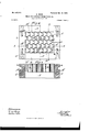
In the drawings, Figure 1 represents a plan of a multiple mold, illustrating one example of my invention; Fig. 2, a section in the line 2 2 of Fig. 1; Fig. 3, a vertical section in the line 3 3 of Fig. 1; Fig. 4, a plan of another example; Fig. 5, a vertical section in the line 5 5 of Fig. 4..
Similar letters of reference designate corresponding parts in all the figures.
Referring first to Figs. 1, 2, and 3, A A designate the mold-box, of iron or steel, and B B two renewable steel molds therein. The mold-box consists of two membersA and A, arranged side by side and clamped together by screw-bolts G G. The molds consist of short pieces of steel tubing of a sectional form, the counterpart of the outline of the tiles to be produced, and are hardened. The cavities in the box which receive the molds B B are formed partly in one and partly in the other member of the box. The said cavity in the memberA conforms to certain portions of the sides of each of the molds, and the cavity in the other member A is more than large enough to contain the other portion of the sides thereof, the spaces left outside of the molds in the said member A being filled with packing-pieces D D, which conform to the box member and to the molds. To set up these packing-pieces and tighten up the molds, tightening screws E E are tapped into the mold box section Aand screwed up against and into notches e e in the said pieces, and these screws are fitted outside of the box member with jam-nuts e e. The clamping screw-bolts O O and the tightening-screws E E all tend to hold the molds with a direct clamping action in the lineof said bolts and tightening-screws, and the screws E E by their action on the packing-pieces D D serve to clamp the molds in a direction transverse to the lines of the bolts and screws. The securing of the molds is further assisted by a pin 1), which is driven through a hole in the member A of the box and into a hole drilled between the adjacent sides of the contiguous molds, partly in one lining and partly in another.
The molds B B are of a height or depth less than the depth of the box, so that their up per ends being flush or thereabout with the top of the box there isaclearance below them within the box, as shown at a a in Fig. 2, to permit the pushing out from the molds of previously-molded tiles by those subsequently molded.
The example of the invention shown in Figs. 4 and 5 differs from that shown in Figs. 1, 2, and 3 and above described in that there is a larger number of molds and the box is made of four separable members A A and A A, each of which forms one of four sides of the box and which are bolted together by screw= bolts 0 C. The molds are of such shape that the exteriors of the sides of any number of them may fit into each other when they are assembled in a group. The two opposite members A A of the box have formed at their ends wedge-shaped projections c c, which engage with corresponding surfaces provided in recesses in the inner faces of the members A-A, so that when the screw-bolts C O are screwed up they tend to draw together all of the four members, those A A being drawn to ward each other by the pull of the screws and those A A being drawn in by the wedges 0 c, and in this way the molds are very tightly clamped together within the box. The movement of the sides A toward each other pro duced by the action of the sides A on the wedge shaped projections, which only requires to be very slight, is provided for by making the holes in the sides A for the bolts C a very little larger than the bolts, as indicated by dotted lines in Fig. 4. To guard additionally against the displacement of the molds within the box, pins Z) are driven through holes provided in the sides of the box and enter holes in the sides of some of the-outer molds of the group, and screw-holes are drilled between contiguous molds at the angles thereof to receive screws (Z d, which are screwed thereinto. This example shown in Figs. .1: and 5 differs from that shown in Figs. 1, 2, and 3 in that instead of the inner faces of the mold-box members being made to conform to the sides of the contiguous molds they are made straight and that instead of detachable filling-pieces,like those D in the first example,the spaces between the box m cmbers and the contiguous molds have a filling D of a metal more fusible than iron or steel- Babbitt metal, for examplewhich is poured into the said spaces in a molten state after the molds have been assembled and clamped up within the box.-
To replace worn-out molds by new ones, it is only necessary to unscrew the bolts C C and draw back the pins 1) sufficiently to permit the worn molds to drop or be knocked out of the box, after which the new ones are put in place and screwed up, as described.
The mold-box constructed as hereinabove described and having the molds assembled and secured within it may be adapted to the bed of any suitable press and the plungers for operation in the molds be attached to the follower or movable head of such press; but as my invention relates only to the molds I have not thought it necessary to represent by drawings either the plungers or any other parts of the press.
Vhat I claim as my invention is- 1. A multiple mold consisting of a series of metal tubes each constituting a mold and the external form of which is such that when assembled together in a group they will fit into each other, a mold-box consisting of separable members in which said molds are assembled, means for clamping said members together and upon the molds, and metal fillings inserted in spaces between the said members and the contiguous molds, substantially as herein described.
2. A multiple mold consisting of a series of metal tubes each constituting a mold and the external form of which is such that when assembled together in a group they will fitinto each other, a mold-box consisting of separable members in which said molds are assembled, metal filling-pieces between the said members and the contiguous molds, clamping-screws for clamping the box members together and tightening-screws for setting up the said filling-pieces, substantially as herein described.
In testimony that I claim the foregoing as my invention I have signed my name, in presence of two witnesses, this 19th day of April, 1899.
GEORGE BASS.
Witnesses:
FREDK. HAYNES, L. M. EGBERT.
Priority Applications (1)
| Application Number | Priority Date | Filing Date | Title |
|---|---|---|---|
| US71369899A US635952A (en) | 1899-04-20 | 1899-04-20 | Mold for manufacturing tiles, &c. |
Applications Claiming Priority (1)
| Application Number | Priority Date | Filing Date | Title |
|---|---|---|---|
| US71369899A US635952A (en) | 1899-04-20 | 1899-04-20 | Mold for manufacturing tiles, &c. |
Publications (1)
| Publication Number | Publication Date |
|---|---|
| US635952A true US635952A (en) | 1899-10-31 |
Family
ID=2704542
Family Applications (1)
| Application Number | Title | Priority Date | Filing Date |
|---|---|---|---|
| US71369899A Expired - Lifetime US635952A (en) | 1899-04-20 | 1899-04-20 | Mold for manufacturing tiles, &c. |
Country Status (1)
| Country | Link |
|---|---|
| US (1) | US635952A (en) |
Cited By (2)
| Publication number | Priority date | Publication date | Assignee | Title |
|---|---|---|---|---|
| US3334857A (en) * | 1965-10-01 | 1967-08-08 | Jay J Liptrap | Mold for concrete blocks |
| US4867668A (en) * | 1986-05-20 | 1989-09-19 | Nissei Jushi Kogyo Kabushiki Kaisha | Mold for plastic molding |
-
1899
- 1899-04-20 US US71369899A patent/US635952A/en not_active Expired - Lifetime
Cited By (2)
| Publication number | Priority date | Publication date | Assignee | Title |
|---|---|---|---|---|
| US3334857A (en) * | 1965-10-01 | 1967-08-08 | Jay J Liptrap | Mold for concrete blocks |
| US4867668A (en) * | 1986-05-20 | 1989-09-19 | Nissei Jushi Kogyo Kabushiki Kaisha | Mold for plastic molding |
Similar Documents
| Publication | Publication Date | Title |
|---|---|---|
| US635952A (en) | Mold for manufacturing tiles, &c. | |
| US680273A (en) | Mold. | |
| US1370191A (en) | Mold for making artificial teeth | |
| US845668A (en) | Mold for making metal castings. | |
| US820759A (en) | Sewer and culvert mold. | |
| US1250233A (en) | Tie-mold. | |
| US849214A (en) | Brick-press box. | |
| US787743A (en) | Mold for forming cement building-blocks. | |
| US969827A (en) | Removable mold for making piano-hammers. | |
| US983678A (en) | Mold for concrete piles or columns. | |
| US1210292A (en) | Mold for making individual teeth for diamond saws. | |
| US814263A (en) | Process of manufacturing pattern-plates. | |
| US1186348A (en) | Cement-mold. | |
| US1229873A (en) | Multiple mold. | |
| US788955A (en) | Machine for molding building-blocks. | |
| US760445A (en) | Molding apparatus for concrete fence-posts. | |
| US1186275A (en) | Mold for artificial stone. | |
| US326289A (en) | graves | |
| US1036867A (en) | Well-tiling and mold therefor. | |
| US581640A (en) | wilson | |
| US770251A (en) | Block-press. | |
| US724614A (en) | Cutting and stamping apparatus. | |
| US688352A (en) | Shingle-mold. | |
| US80358A (en) | Thomas j | |
| US811474A (en) | Mold. |