US6340284B1 - Turbine blade with actively cooled shroud-band element - Google Patents
Turbine blade with actively cooled shroud-band element Download PDFInfo
- Publication number
- US6340284B1 US6340284B1 US09/471,410 US47141099A US6340284B1 US 6340284 B1 US6340284 B1 US 6340284B1 US 47141099 A US47141099 A US 47141099A US 6340284 B1 US6340284 B1 US 6340284B1
- Authority
- US
- United States
- Prior art keywords
- cooling
- shroud
- turbine blade
- band element
- blade
- Prior art date
- Legal status (The legal status is an assumption and is not a legal conclusion. Google has not performed a legal analysis and makes no representation as to the accuracy of the status listed.)
- Expired - Lifetime
Links
Images


Classifications
-
- F—MECHANICAL ENGINEERING; LIGHTING; HEATING; WEAPONS; BLASTING
- F01—MACHINES OR ENGINES IN GENERAL; ENGINE PLANTS IN GENERAL; STEAM ENGINES
- F01D—NON-POSITIVE DISPLACEMENT MACHINES OR ENGINES, e.g. STEAM TURBINES
- F01D5/00—Blades; Blade-carrying members; Heating, heat-insulating, cooling or antivibration means on the blades or the members
- F01D5/12—Blades
- F01D5/22—Blade-to-blade connections, e.g. for damping vibrations
- F01D5/225—Blade-to-blade connections, e.g. for damping vibrations by shrouding
-
- F—MECHANICAL ENGINEERING; LIGHTING; HEATING; WEAPONS; BLASTING
- F01—MACHINES OR ENGINES IN GENERAL; ENGINE PLANTS IN GENERAL; STEAM ENGINES
- F01D—NON-POSITIVE DISPLACEMENT MACHINES OR ENGINES, e.g. STEAM TURBINES
- F01D5/00—Blades; Blade-carrying members; Heating, heat-insulating, cooling or antivibration means on the blades or the members
- F01D5/12—Blades
- F01D5/14—Form or construction
- F01D5/18—Hollow blades, i.e. blades with cooling or heating channels or cavities; Heating, heat-insulating or cooling means on blades
- F01D5/187—Convection cooling
-
- F—MECHANICAL ENGINEERING; LIGHTING; HEATING; WEAPONS; BLASTING
- F05—INDEXING SCHEMES RELATING TO ENGINES OR PUMPS IN VARIOUS SUBCLASSES OF CLASSES F01-F04
- F05B—INDEXING SCHEME RELATING TO WIND, SPRING, WEIGHT, INERTIA OR LIKE MOTORS, TO MACHINES OR ENGINES FOR LIQUIDS COVERED BY SUBCLASSES F03B, F03D AND F03G
- F05B2240/00—Components
- F05B2240/80—Platforms for stationary or moving blades
- F05B2240/801—Platforms for stationary or moving blades cooled platforms
-
- F—MECHANICAL ENGINEERING; LIGHTING; HEATING; WEAPONS; BLASTING
- F05—INDEXING SCHEMES RELATING TO ENGINES OR PUMPS IN VARIOUS SUBCLASSES OF CLASSES F01-F04
- F05D—INDEXING SCHEME FOR ASPECTS RELATING TO NON-POSITIVE-DISPLACEMENT MACHINES OR ENGINES, GAS-TURBINES OR JET-PROPULSION PLANTS
- F05D2240/00—Components
- F05D2240/80—Platforms for stationary or moving blades
- F05D2240/81—Cooled platforms
Definitions
- the present invention relates to the field of gas turbines, and more particularly to air-cooled turbine blades
- the cooling effect is mainly based on the mixing temperature in the shroud-band surroundings, the mixing temperature being lowered by mixing of the discharging cooling air with the hot gas. No measures are taken in the cooling bores in order to intensify the heat transfer between the cooling air and the shroud-band element.
- the object of the invention is therefore to provide a turbine blade having an air-cooled shroud-band element, in which turbine blade the abovementioned disadvantages are avoided in a simple manner and which is distinguished by effective cooling of the shroud-band element, in particular on the exposed top side of the shroud-band element.
- the basic idea of the invention consists, on the one hand, in directing the cooling bores through the shroud-band element in such a way that considerable heat transfer between the shroud-band element and cooling air is ensured and, on the other hand, in making these bores open into the exterior space in such a way that the cooling air is reliably admitted to the exposed regions of the shroud band and these regions are additionally cooled.
- This is achieved by virtue of the fact that, starting from the cooling passage in the blade, the cooling bores, in the region of the shroud-band element, run from inside to outside essentially parallel to the direction of movement of the blade tip and in each case open upstream of the outer margin of the shroud-bank element into a surface recess open toward the exterior space.
- recesses, into which the cooling bores open laterally are sunk in the shroud-band element close to the outer margin from the top side. Due to the discharging cooling air mixing with the hot combustion gases which flow over the top side of the shroud-band element, the temperature in this region is effectively reduced and thus overheating of the shroud band is avoided. In this way, uniform cooling of the shroud-band element over the entire surface is achieved. In addition to effective cooling of the top side of the shroud band, this configuration also has the advantage of very simple manufacture.
- the discharge of the cooling air on the top side of the shroud-band element is especially effective if, in a preferred development, spaced-apart sealing ribs running parallel to one another are provided on the top side of the shroud-band element and form a cavity in interaction with the opposite casing wall of the gas turbine, and the cooling bores open into this cavity.
- the discharging cooling air leads to a pressure build-up in the cavity, the result of which is that the penetration of hot gases is reduced.
- the side edges of the shroud-band elements have recessed portions, into which the cooling bores open.
- the recessed portions of opposite shroud-band elements form a gap.
- the cooling air splits up into two partial flows.
- One part flows toward the top side and has the above mentioned effect on the above mentioned cavity between the space-apart sealing ribs.
- the other part flows toward the underside of the shroud bank and mixes there with the hot gases while setting a mixing temperature which reduces the thermal loading in this region.
- the ratio of the partial quantities flowing off upward and downward can be influenced by the gap geometry.
- means for improving the heat transfer between cooling air and shroud-band element be provided in the cooling bores.
- the means for improving the heat transfer at the bore walls may comprise roughness features, ribs and/or turbulence points.
- the bores may be produced by means of the so-called STEM drilling process. Cooling bores having improved heat-transfer properties can be produced in a simple and reliable manner especially by STEM drilling, which has been described, for example, in U.S. Pat. No. 5,306,401 in connection with the production of cooling holes in turbine blades.
- a choke point for limiting the cooling-air mass flow is provided in each of the cooling bores, and the choke points are each arranged on the inlet side of the cooling bores.
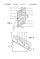
- FIG. 1 shows a plan view of a preferred embodiment of the turbine blade with cooling bores discharging toward the top side of the shroud band
- FIG. 2 shows a modified form of the embodiment of FIG. 1 with diffuser-like cooling bores
- FIG. 3 shows a side view of the second modified form of the embodiment of FIG. 1 with cooling bores of circular cross section.
- FIG. 4 shows a side view of a third modified form of the embodiment of FIG. 1 with cooling bores of oval cross section
- FIG. 5 shows a partial sectional view of a shroud-band element along the line 5 — 5 in FIG. 1
- FIG. 6 shows a plan view of a fourth modified form of the embodiment of FIG. 1 having two shroud-band elements in with cooling bores discharging toward the side edge
- FIG. 7 shows a partial sectional view of a fifth modified form of the shroud-band element along the line 7 — 7 in FIG. 6
- FIG. 8 shows a partial sectional view of a sixth modified form of the embodiment as in FIG. 7 of a shroud-band element with cooling air discharge toward the underside of the shroud-band element
- FIG. 1 A preferred embodiment of a turbine blade according to the invention is shown in plan view in FIG. 1 .
- the turbine blade 10 comprises the actual blade profile 23 and a shroud-band element 11 , which is arranged at the blade tip transversely to the blade profile 23 and, together with the shroud-band elements of the other blades (not shown), produces a continuous, mechanically stabilizing shroud band.
- the blade profile 23 is partly hollow in the interior, and passing through the blade: profile 23 are one or more cooling-air passages 18 , which direct cooling air from the blade root up to the blade tip.
- the shroud-band element 11 On its top side, the shroud-band element 11 has two sealing ribs 12 and 13 , which run in parallel in the direction of movement of the blade tip and, together with the opposite casing wall 20 of the gas turbine, form a cavity 21 connected to the surrounding environment by gaps.
- a plurality of cooling bores 17 run from the center outward between and essentially parallel to the ribs 12 , 13 .
- the cooling bores 17 are connected to the cooling-air passage 18 and are supplied with cooling air from the latter. As can be seen from FIG.
- the cooling bores 17 do not extend quite up to the lateral end or margin of the shroud-band element 11 but open in each case from the side into an elongated recess 14 sunk in the shroud-band element 11 on the top side 22 . It goes without saying that, instead of a continuous recess 14 , each of the cooling bores 17 taken by itself may also be connected to a separate recess. Furthermore, it is also conceivable for the cooling bores 17 to run at a slight angle and to deviate from an arrangement in parallel with one another, if this is necessary in order to optimize the cooling over the entire surface of the shroud-band element 11 .
- blow-out of the cooling air upward leads to an “inflation” of the cavity 21 between shroud-band and casing 20 .
- This leads to an increase in the pressure in the cavity and thus helps to reduce the penetrating mass flow of hot gas 24 .
- the mixing temperature in this region is of course also lowered, as a result of which the thermal loading of the shroud-band element 11 from the top side 22 is reduced.
- the cooling bores 17 in the cooling arrangement shown are preferably produced by the so-called STEM drilling method, which is fully described in detail in U.S. Pat. No. 5,306,401.
- STEM drilling method which is fully described in detail in U.S. Pat. No. 5,306,401.
- a choke point 19 in each case, preferably on the inlet side, i.e. in the region of the cooling-air supply at the profile 23 .
- cooling bores 17 differs from that according to FIG. 1 in that the cooling bores 17 , starting from the choke point 19 , which is arranged in each case on the inlet side of each cooling bore, are designed as a diffuser or in a diffuser-like manner.
- the cooling bores have an oval configuration. Like the surface provided with inner roughness features or like the diffuser-like widening, this increases the effective surface available for the heat transfer.
- the cooling bores 17 may have configurations different from those described above. Such configurations may be, for example, regularly or irregularly maintained recesses or undulations.
- the cooling bores 17 discharge at the side edge 25 of the shroud-band element 11 .
- the side edges 25 of, the shroud-band elements 11 are designed such that adjacent elements 11 are only in contact zonally, whereas the region of the discharging cooling bores is set back in a recess 15 . Between the adjacent elements, the opposite recesses 15 form gaps 26 , into which the cooling air enters.
- This embodiment reliably prevents closure of the orifices by adjacent shroud-band elements. It ensures that the cooling air can always pass through the cooling bores 17 , even if two adjacent shroud-band elements 11 are in mechanical contact.
- the cooling air entering the gap 26 from both adjacent elements 11 splits up into two partial flows.
- One partial flow flows upward and leads to inflation of the cavity 21 above the shroud band, whereas the other partial flow passes to the underside of the shroud band and mixes there with the hot gases.
- the mixing temperature which occurs reduces the thermal loading in this region.
- the volumetric ratio of the two partial flows can be influenced by the design of the gap.
- the top side and under side may have a different gap width or the boundary walls may be inclined or designed differently from the fluidic point of view.
- FIG. 8 shows an embodiment with cooling-medium discharge on the underside of the shroud-band element.
- the cooling bores 17 open laterally into the recess 16 .
- the mixing temperature in the region of the underside of the shroud band is lowered and thus the thermal loading is reduced.
Landscapes
- Engineering & Computer Science (AREA)
- Mechanical Engineering (AREA)
- General Engineering & Computer Science (AREA)
- Turbine Rotor Nozzle Sealing (AREA)
Abstract
Description
Claims (13)
Applications Claiming Priority (4)
| Application Number | Priority Date | Filing Date | Title |
|---|---|---|---|
| DE19860244A DE19860244B4 (en) | 1998-12-24 | 1998-12-24 | Turbine blade with actively cooled shroud element |
| DE19860245 | 1998-12-24 | ||
| DE19860245A DE19860245A1 (en) | 1998-12-24 | 1998-12-24 | Air cooled blade for gas turbine has cooling holes in shroud element running from inside outwards and parallel to direction of blade's movement, with each cooling hole opening out into surface recess before outer edge of shroud element |
| DE19860244 | 1998-12-24 |
Publications (1)
| Publication Number | Publication Date |
|---|---|
| US6340284B1 true US6340284B1 (en) | 2002-01-22 |
Family
ID=26051058
Family Applications (1)
| Application Number | Title | Priority Date | Filing Date |
|---|---|---|---|
| US09/471,410 Expired - Lifetime US6340284B1 (en) | 1998-12-24 | 1999-12-23 | Turbine blade with actively cooled shroud-band element |
Country Status (4)
| Country | Link |
|---|---|
| US (1) | US6340284B1 (en) |
| EP (1) | EP1013884B1 (en) |
| CN (1) | CN1260442A (en) |
| DE (1) | DE59912323D1 (en) |
Cited By (35)
| Publication number | Priority date | Publication date | Assignee | Title |
|---|---|---|---|---|
| JP2001132406A (en) * | 1999-09-07 | 2001-05-15 | General Electric Co <Ge> | Internally cooled blade tip shroud |
| US6464460B2 (en) * | 1999-12-28 | 2002-10-15 | Alstom (Switzerland) Ltd | Turbine blade with actively cooled shroud-band element |
| US6471480B1 (en) * | 2001-04-16 | 2002-10-29 | United Technologies Corporation | Thin walled cooled hollow tip shroud |
| US6491498B1 (en) * | 2001-10-04 | 2002-12-10 | Power Systems Mfg, Llc. | Turbine blade pocket shroud |
| US6499950B2 (en) | 1999-04-01 | 2002-12-31 | Fred Thomas Willett | Cooling circuit for a gas turbine bucket and tip shroud |
| US6632069B1 (en) * | 2001-10-02 | 2003-10-14 | Oleg Naljotov | Step of pressure of the steam and gas turbine with universal belt |
| US20040101410A1 (en) * | 2001-10-02 | 2004-05-27 | Oleg Naljotov | Axial flow fluid machine |
| US6761534B1 (en) | 1999-04-05 | 2004-07-13 | General Electric Company | Cooling circuit for a gas turbine bucket and tip shroud |
| WO2004099572A1 (en) * | 2003-04-18 | 2004-11-18 | Oleg Naljotov | Steam/gas turbine pressure stage with universal shroud |
| US20050214120A1 (en) * | 2004-03-26 | 2005-09-29 | The Boeing Company | High speed rotor assembly shroud |
| US7074006B1 (en) | 2002-10-08 | 2006-07-11 | The United States Of America As Represented By The Administrator Of National Aeronautics And Space Administration | Endwall treatment and method for gas turbine |
| RU2285806C1 (en) * | 2004-02-09 | 2006-10-20 | Юнайтид Текнолоджиз Копэрейшн | Turbine blade for gas-turbine engine, its shroud and method of manufacture |
| KR100758725B1 (en) | 2005-10-17 | 2007-09-14 | 올레지 날조토브 | Steam / Gas Turbine Pressure Stages with Universal Shroud |
| US20080170946A1 (en) * | 2007-01-12 | 2008-07-17 | General Electric Company | Impingement cooled bucket shroud, turbine rotor incorporating the same, and cooling method |
| US20080230378A1 (en) * | 2007-03-22 | 2008-09-25 | General Electric Company | Methods and systems for forming tapered cooling holes |
| US20080230379A1 (en) * | 2007-03-22 | 2008-09-25 | General Electric Company | Methods and systems for forming cooling holes having circular inlets and non-circular outlets |
| US20080230396A1 (en) * | 2007-03-22 | 2008-09-25 | General Electric Company | Methods and systems for forming turbulated cooling holes |
| US20090180894A1 (en) * | 2008-01-10 | 2009-07-16 | General Electric Company | Turbine blade tip shroud |
| US20090180892A1 (en) * | 2008-01-10 | 2009-07-16 | General Electric Company | Turbine blade tip shroud |
| US20090180893A1 (en) * | 2008-01-10 | 2009-07-16 | General Electric Company | Turbine blade tip shroud |
| US20090180895A1 (en) * | 2008-01-10 | 2009-07-16 | General Electric Company | Turbine blade tip shroud |
| US20100054914A1 (en) * | 2008-08-27 | 2010-03-04 | Susan Tholen | Gas turbine engine component having dual flow passage cooling chamber formed by single core |
| US20100189569A1 (en) * | 2009-01-26 | 2010-07-29 | Rolls-Royce Plc | Rotor blade |
| US20100316486A1 (en) * | 2009-06-15 | 2010-12-16 | Rolls-Royce Plc | Cooled component for a gas turbine engine |
| US20120070309A1 (en) * | 2009-03-30 | 2012-03-22 | Alstom Technology Ltd. | Blade for a gas turbine |
| CN103228871A (en) * | 2010-12-22 | 2013-07-31 | 三菱重工业株式会社 | Turbine |
| US20140064984A1 (en) * | 2012-08-31 | 2014-03-06 | General Electric Company | Cooling arrangement for platform region of turbine rotor blade |
| CN103912519A (en) * | 2013-01-09 | 2014-07-09 | 发那科株式会社 | Method of formation of impeller with shape defined by plurality of lines and such impeller |
| US20150064010A1 (en) * | 2013-08-28 | 2015-03-05 | General Electric Company | Turbine Bucket Tip Shroud |
| WO2015047576A1 (en) | 2013-09-26 | 2015-04-02 | United Technologies Corporation | Diffused platform cooling holes |
| US20160251980A1 (en) * | 2013-10-21 | 2016-09-01 | United Technologies Corporation | Incident tolerant turbine vane gap flow discouragement |
| US10539026B2 (en) | 2017-09-21 | 2020-01-21 | United Technologies Corporation | Gas turbine engine component with cooling holes having variable roughness |
| US11255198B1 (en) * | 2021-06-10 | 2022-02-22 | General Electric Company | Tip shroud with exit surface for cooling passages |
| CN114555912A (en) * | 2019-11-14 | 2022-05-27 | 三菱重工业株式会社 | Turbine blade and gas turbine |
| CN115324657A (en) * | 2022-10-12 | 2022-11-11 | 中国航发四川燃气涡轮研究院 | Turbine working blade shroud cooling structure |
Families Citing this family (5)
| Publication number | Priority date | Publication date | Assignee | Title |
|---|---|---|---|---|
| JP2002371802A (en) * | 2001-06-14 | 2002-12-26 | Mitsubishi Heavy Ind Ltd | Shroud integrated type moving blade in gas turbine and split ring |
| EP1591626A1 (en) | 2004-04-30 | 2005-11-02 | Alstom Technology Ltd | Blade for gas turbine |
| US8353669B2 (en) * | 2009-08-18 | 2013-01-15 | United Technologies Corporation | Turbine vane platform leading edge cooling holes |
| DE102009049649A1 (en) * | 2009-10-15 | 2011-04-21 | Abb Turbo Systems Ag | turbine |
| US10641108B2 (en) * | 2018-04-06 | 2020-05-05 | United Technologies Corporation | Turbine blade shroud for gas turbine engine with power turbine and method of manufacturing same |
Citations (19)
| Publication number | Priority date | Publication date | Assignee | Title |
|---|---|---|---|---|
| US3527544A (en) * | 1968-12-12 | 1970-09-08 | Gen Motors Corp | Cooled blade shroud |
| DE2319743A1 (en) | 1972-04-20 | 1973-10-31 | Rolls Royce 1971 Ltd | ROTOR BLADE FOR FLOW MACHINERY |
| DE2343639A1 (en) | 1972-09-01 | 1974-03-07 | Gen Electric | ROTATING BLADE ENDS WITH PERFORMANCE INCREASE FOR TURBINES WITH COOLING THROUGH OPEN LIQUID CIRCUIT |
| US4177011A (en) | 1976-04-21 | 1979-12-04 | General Electric Company | Bar for sealing the gap between adjacent shroud plates in liquid-cooled gas turbine |
| JPS5847104A (en) * | 1981-09-11 | 1983-03-18 | Agency Of Ind Science & Technol | Turbine rotor blade in gas turbine |
| US4940388A (en) * | 1988-12-07 | 1990-07-10 | Rolls-Royce Plc | Cooling of turbine blades |
| US4948338A (en) * | 1988-09-30 | 1990-08-14 | Rolls-Royce Plc | Turbine blade with cooled shroud abutment surface |
| JPH03182602A (en) * | 1989-12-08 | 1991-08-08 | Hitachi Ltd | Gas turbine blade with cooling passage and cooling passage machining method thereof |
| GB1605335A (en) | 1975-08-23 | 1991-12-18 | Rolls Royce | A rotor blade for a gas turbine engine |
| US5306401A (en) | 1993-03-15 | 1994-04-26 | Fierkens Richard H J | Method for drilling cooling holes in turbine blades |
| US5399065A (en) | 1992-09-03 | 1995-03-21 | Hitachi, Ltd. | Improvements in cooling and sealing for a gas turbine cascade device |
| US5460486A (en) | 1992-11-19 | 1995-10-24 | Bmw Rolls-Royce Gmbh | Gas turbine blade having improved thermal stress cooling ducts |
| US5482435A (en) | 1994-10-26 | 1996-01-09 | Westinghouse Electric Corporation | Gas turbine blade having a cooled shroud |
| GB2290833A (en) | 1994-07-02 | 1996-01-10 | Rolls Royce Plc | Turbine blade cooling |
| US5785496A (en) | 1997-02-24 | 1998-07-28 | Mitsubishi Heavy Industries, Ltd. | Gas turbine rotor |
| DE19813173A1 (en) | 1997-03-25 | 1998-10-01 | Mitsubishi Heavy Ind Ltd | Cooled gas turbine blade |
| US6146098A (en) * | 1997-06-23 | 2000-11-14 | Mitsubishi Heavy Industries, Ltd. | Tip shroud for cooled blade of gas turbine |
| US6152695A (en) * | 1998-02-04 | 2000-11-28 | Mitsubishi Heavy Industries, Ltd. | Gas turbine moving blade |
| JP3182602B2 (en) | 1995-03-31 | 2001-07-03 | 矢崎総業株式会社 | Absorption chiller / heater and its control method |
Family Cites Families (4)
| Publication number | Priority date | Publication date | Assignee | Title |
|---|---|---|---|---|
| US5003766A (en) * | 1984-10-10 | 1991-04-02 | Paul Marius A | Gas turbine engine |
| US4902198A (en) * | 1988-08-31 | 1990-02-20 | Westinghouse Electric Corp. | Apparatus for film cooling of turbine van shrouds |
| US5122033A (en) * | 1990-11-16 | 1992-06-16 | Paul Marius A | Turbine blade unit |
| GB2298246B (en) * | 1995-02-23 | 1998-10-28 | Bmw Rolls Royce Gmbh | A turbine-blade arrangement comprising a shroud band |
-
1999
- 1999-12-21 DE DE59912323T patent/DE59912323D1/en not_active Expired - Lifetime
- 1999-12-21 EP EP99811187A patent/EP1013884B1/en not_active Expired - Lifetime
- 1999-12-23 US US09/471,410 patent/US6340284B1/en not_active Expired - Lifetime
- 1999-12-24 CN CN99124987A patent/CN1260442A/en active Pending
Patent Citations (20)
| Publication number | Priority date | Publication date | Assignee | Title |
|---|---|---|---|---|
| US3527544A (en) * | 1968-12-12 | 1970-09-08 | Gen Motors Corp | Cooled blade shroud |
| DE2319743A1 (en) | 1972-04-20 | 1973-10-31 | Rolls Royce 1971 Ltd | ROTOR BLADE FOR FLOW MACHINERY |
| DE2343639A1 (en) | 1972-09-01 | 1974-03-07 | Gen Electric | ROTATING BLADE ENDS WITH PERFORMANCE INCREASE FOR TURBINES WITH COOLING THROUGH OPEN LIQUID CIRCUIT |
| US3816022A (en) * | 1972-09-01 | 1974-06-11 | Gen Electric | Power augmenter bucket tip construction for open-circuit liquid cooled turbines |
| GB1605335A (en) | 1975-08-23 | 1991-12-18 | Rolls Royce | A rotor blade for a gas turbine engine |
| US4177011A (en) | 1976-04-21 | 1979-12-04 | General Electric Company | Bar for sealing the gap between adjacent shroud plates in liquid-cooled gas turbine |
| JPS5847104A (en) * | 1981-09-11 | 1983-03-18 | Agency Of Ind Science & Technol | Turbine rotor blade in gas turbine |
| US4948338A (en) * | 1988-09-30 | 1990-08-14 | Rolls-Royce Plc | Turbine blade with cooled shroud abutment surface |
| US4940388A (en) * | 1988-12-07 | 1990-07-10 | Rolls-Royce Plc | Cooling of turbine blades |
| JPH03182602A (en) * | 1989-12-08 | 1991-08-08 | Hitachi Ltd | Gas turbine blade with cooling passage and cooling passage machining method thereof |
| US5399065A (en) | 1992-09-03 | 1995-03-21 | Hitachi, Ltd. | Improvements in cooling and sealing for a gas turbine cascade device |
| US5460486A (en) | 1992-11-19 | 1995-10-24 | Bmw Rolls-Royce Gmbh | Gas turbine blade having improved thermal stress cooling ducts |
| US5306401A (en) | 1993-03-15 | 1994-04-26 | Fierkens Richard H J | Method for drilling cooling holes in turbine blades |
| GB2290833A (en) | 1994-07-02 | 1996-01-10 | Rolls Royce Plc | Turbine blade cooling |
| US5482435A (en) | 1994-10-26 | 1996-01-09 | Westinghouse Electric Corporation | Gas turbine blade having a cooled shroud |
| JP3182602B2 (en) | 1995-03-31 | 2001-07-03 | 矢崎総業株式会社 | Absorption chiller / heater and its control method |
| US5785496A (en) | 1997-02-24 | 1998-07-28 | Mitsubishi Heavy Industries, Ltd. | Gas turbine rotor |
| DE19813173A1 (en) | 1997-03-25 | 1998-10-01 | Mitsubishi Heavy Ind Ltd | Cooled gas turbine blade |
| US6146098A (en) * | 1997-06-23 | 2000-11-14 | Mitsubishi Heavy Industries, Ltd. | Tip shroud for cooled blade of gas turbine |
| US6152695A (en) * | 1998-02-04 | 2000-11-28 | Mitsubishi Heavy Industries, Ltd. | Gas turbine moving blade |
Cited By (62)
| Publication number | Priority date | Publication date | Assignee | Title |
|---|---|---|---|---|
| US6499950B2 (en) | 1999-04-01 | 2002-12-31 | Fred Thomas Willett | Cooling circuit for a gas turbine bucket and tip shroud |
| US6761534B1 (en) | 1999-04-05 | 2004-07-13 | General Electric Company | Cooling circuit for a gas turbine bucket and tip shroud |
| JP2001132406A (en) * | 1999-09-07 | 2001-05-15 | General Electric Co <Ge> | Internally cooled blade tip shroud |
| US6464460B2 (en) * | 1999-12-28 | 2002-10-15 | Alstom (Switzerland) Ltd | Turbine blade with actively cooled shroud-band element |
| US6471480B1 (en) * | 2001-04-16 | 2002-10-29 | United Technologies Corporation | Thin walled cooled hollow tip shroud |
| US6632069B1 (en) * | 2001-10-02 | 2003-10-14 | Oleg Naljotov | Step of pressure of the steam and gas turbine with universal belt |
| US20040101410A1 (en) * | 2001-10-02 | 2004-05-27 | Oleg Naljotov | Axial flow fluid machine |
| US6491498B1 (en) * | 2001-10-04 | 2002-12-10 | Power Systems Mfg, Llc. | Turbine blade pocket shroud |
| WO2003029616A1 (en) * | 2001-10-04 | 2003-04-10 | Power Systems Mfg, Llc | Turbine blade pocket shroud |
| KR100831803B1 (en) | 2001-10-04 | 2008-05-28 | 파워 시스템즈 엠에프지., 엘엘씨 | Turbine Blade Pocket Shroud |
| US7074006B1 (en) | 2002-10-08 | 2006-07-11 | The United States Of America As Represented By The Administrator Of National Aeronautics And Space Administration | Endwall treatment and method for gas turbine |
| AU2003228590B2 (en) * | 2003-04-18 | 2010-01-07 | Oleg Naljotov | Steam/gas turbine pressure stage with universal shroud |
| WO2004099572A1 (en) * | 2003-04-18 | 2004-11-18 | Oleg Naljotov | Steam/gas turbine pressure stage with universal shroud |
| EA008156B1 (en) * | 2003-04-18 | 2007-04-27 | Олег Налётов | Stream/gas turbine pressure stage with universal shroud |
| CN100386502C (en) * | 2003-04-18 | 2008-05-07 | 奥莱格·耐尔卓托夫 | Steam/gas turbine with improved shroud or seal |
| RU2285806C1 (en) * | 2004-02-09 | 2006-10-20 | Юнайтид Текнолоджиз Копэрейшн | Turbine blade for gas-turbine engine, its shroud and method of manufacture |
| US20050214120A1 (en) * | 2004-03-26 | 2005-09-29 | The Boeing Company | High speed rotor assembly shroud |
| US7066714B2 (en) | 2004-03-26 | 2006-06-27 | United Technologies Corporation | High speed rotor assembly shroud |
| KR100758725B1 (en) | 2005-10-17 | 2007-09-14 | 올레지 날조토브 | Steam / Gas Turbine Pressure Stages with Universal Shroud |
| CN101235728B (en) * | 2007-01-12 | 2013-05-01 | 通用电气公司 | Impingement cooled bucket shroud, turbine rotor incorporating the same, and cooling method |
| US20080170946A1 (en) * | 2007-01-12 | 2008-07-17 | General Electric Company | Impingement cooled bucket shroud, turbine rotor incorporating the same, and cooling method |
| US7568882B2 (en) * | 2007-01-12 | 2009-08-04 | General Electric Company | Impingement cooled bucket shroud, turbine rotor incorporating the same, and cooling method |
| US20080230378A1 (en) * | 2007-03-22 | 2008-09-25 | General Electric Company | Methods and systems for forming tapered cooling holes |
| US20080230396A1 (en) * | 2007-03-22 | 2008-09-25 | General Electric Company | Methods and systems for forming turbulated cooling holes |
| US7964087B2 (en) | 2007-03-22 | 2011-06-21 | General Electric Company | Methods and systems for forming cooling holes having circular inlets and non-circular outlets |
| US20080230379A1 (en) * | 2007-03-22 | 2008-09-25 | General Electric Company | Methods and systems for forming cooling holes having circular inlets and non-circular outlets |
| US7938951B2 (en) | 2007-03-22 | 2011-05-10 | General Electric Company | Methods and systems for forming tapered cooling holes |
| US7946817B2 (en) * | 2008-01-10 | 2011-05-24 | General Electric Company | Turbine blade tip shroud |
| US20090180895A1 (en) * | 2008-01-10 | 2009-07-16 | General Electric Company | Turbine blade tip shroud |
| US20090180893A1 (en) * | 2008-01-10 | 2009-07-16 | General Electric Company | Turbine blade tip shroud |
| US20090180892A1 (en) * | 2008-01-10 | 2009-07-16 | General Electric Company | Turbine blade tip shroud |
| US7946816B2 (en) * | 2008-01-10 | 2011-05-24 | General Electric Company | Turbine blade tip shroud |
| US20090180894A1 (en) * | 2008-01-10 | 2009-07-16 | General Electric Company | Turbine blade tip shroud |
| US8057177B2 (en) * | 2008-01-10 | 2011-11-15 | General Electric Company | Turbine blade tip shroud |
| US20100054914A1 (en) * | 2008-08-27 | 2010-03-04 | Susan Tholen | Gas turbine engine component having dual flow passage cooling chamber formed by single core |
| US8317461B2 (en) | 2008-08-27 | 2012-11-27 | United Technologies Corporation | Gas turbine engine component having dual flow passage cooling chamber formed by single core |
| US20100189569A1 (en) * | 2009-01-26 | 2010-07-29 | Rolls-Royce Plc | Rotor blade |
| US8366393B2 (en) * | 2009-01-26 | 2013-02-05 | Rolls-Royce Plc | Rotor blade |
| US9464529B2 (en) * | 2009-03-30 | 2016-10-11 | General Electric Technology Gmbh | Blade for a gas turbine |
| AU2010230482B2 (en) * | 2009-03-30 | 2014-12-04 | Ansaldo Energia Ip Uk Limited | Blade for a gas turbine |
| RU2543641C2 (en) * | 2009-03-30 | 2015-03-10 | Альстом Текнолоджи Лтд. | Gas turbine blade |
| US20120070309A1 (en) * | 2009-03-30 | 2012-03-22 | Alstom Technology Ltd. | Blade for a gas turbine |
| US20100316486A1 (en) * | 2009-06-15 | 2010-12-16 | Rolls-Royce Plc | Cooled component for a gas turbine engine |
| US8573925B2 (en) * | 2009-06-15 | 2013-11-05 | Rolls-Royce Plc | Cooled component for a gas turbine engine |
| CN103228871B (en) * | 2010-12-22 | 2015-07-15 | 三菱日立电力系统株式会社 | Turbine |
| CN103228871A (en) * | 2010-12-22 | 2013-07-31 | 三菱重工业株式会社 | Turbine |
| US9353640B2 (en) | 2010-12-22 | 2016-05-31 | Mitsubishi Hitachi Power Systems, Ltd. | Turbine |
| US20140064984A1 (en) * | 2012-08-31 | 2014-03-06 | General Electric Company | Cooling arrangement for platform region of turbine rotor blade |
| CN103912519B (en) * | 2013-01-09 | 2015-08-05 | 发那科株式会社 | The impeller that shape is defined by many straight lines form method and impeller |
| CN103912519A (en) * | 2013-01-09 | 2014-07-09 | 发那科株式会社 | Method of formation of impeller with shape defined by plurality of lines and such impeller |
| US9416664B2 (en) | 2013-01-09 | 2016-08-16 | Fanuc Corporation | Method of formation of impeller with shape defined by plurality of lines and such impeller |
| US20150064010A1 (en) * | 2013-08-28 | 2015-03-05 | General Electric Company | Turbine Bucket Tip Shroud |
| US9759070B2 (en) * | 2013-08-28 | 2017-09-12 | General Electric Company | Turbine bucket tip shroud |
| EP3049633A4 (en) * | 2013-09-26 | 2016-10-26 | COOLING HOLES OF DIFFUSION PLATFORM | |
| WO2015047576A1 (en) | 2013-09-26 | 2015-04-02 | United Technologies Corporation | Diffused platform cooling holes |
| US20160169001A1 (en) * | 2013-09-26 | 2016-06-16 | United Technologies Corporation | Diffused platform cooling holes |
| US20160251980A1 (en) * | 2013-10-21 | 2016-09-01 | United Technologies Corporation | Incident tolerant turbine vane gap flow discouragement |
| US10301967B2 (en) * | 2013-10-21 | 2019-05-28 | United Technologies Corporation | Incident tolerant turbine vane gap flow discouragement |
| US10539026B2 (en) | 2017-09-21 | 2020-01-21 | United Technologies Corporation | Gas turbine engine component with cooling holes having variable roughness |
| CN114555912A (en) * | 2019-11-14 | 2022-05-27 | 三菱重工业株式会社 | Turbine blade and gas turbine |
| US11255198B1 (en) * | 2021-06-10 | 2022-02-22 | General Electric Company | Tip shroud with exit surface for cooling passages |
| CN115324657A (en) * | 2022-10-12 | 2022-11-11 | 中国航发四川燃气涡轮研究院 | Turbine working blade shroud cooling structure |
Also Published As
| Publication number | Publication date |
|---|---|
| EP1013884B1 (en) | 2005-07-27 |
| EP1013884A2 (en) | 2000-06-28 |
| DE59912323D1 (en) | 2005-09-01 |
| CN1260442A (en) | 2000-07-19 |
| EP1013884A3 (en) | 2003-11-05 |
Similar Documents
| Publication | Publication Date | Title |
|---|---|---|
| US6340284B1 (en) | Turbine blade with actively cooled shroud-band element | |
| US7887294B1 (en) | Turbine airfoil with continuous curved diffusion film holes | |
| US6379118B2 (en) | Cooled blade for a gas turbine | |
| US7195458B2 (en) | Impingement cooling system for a turbine blade | |
| US6464460B2 (en) | Turbine blade with actively cooled shroud-band element | |
| US5399065A (en) | Improvements in cooling and sealing for a gas turbine cascade device | |
| US6347923B1 (en) | Coolable blade for a gas turbine | |
| KR100569765B1 (en) | Turbine blade | |
| US6916150B2 (en) | Cooling system for a tip of a turbine blade | |
| US7033136B2 (en) | Cooling circuits for a gas turbine blade | |
| US7056093B2 (en) | Gas turbine aerofoil | |
| US6705836B2 (en) | Gas turbine blade cooling circuits | |
| EP0971095B1 (en) | A coolable airfoil for a gas turbine engine | |
| US7435053B2 (en) | Turbine blade cooling system having multiple serpentine trailing edge cooling channels | |
| US7427188B2 (en) | Turbomachine blade with fluidically cooled shroud | |
| CN101535602B (en) | Turbine blade | |
| US6099244A (en) | Cooled stationary blade for a gas turbine | |
| EP2564028B1 (en) | Gas turbine blade | |
| CN100350132C (en) | Turbine blade | |
| EP0924385A2 (en) | Turbine blades | |
| US6309175B1 (en) | Platform cooling in turbomachines | |
| KR20070006875A (en) | Blades for Gas Turbines | |
| US6068445A (en) | Cooling system for the leading-edge region of a hollow gas-turbine blade | |
| US6328532B1 (en) | Blade cooling | |
| JP2002540347A (en) | Apparatus and method for manufacturing cast gas turbine blade through which coolant flows and distribution chamber of gas turbine blade |
Legal Events
| Date | Code | Title | Description |
|---|---|---|---|
| AS | Assignment |
Owner name: ABB ALSTOM POWER (SCHWEIZ) AG, SWITZERLAND Free format text: ASSIGNMENT OF ASSIGNORS INTEREST;ASSIGNORS:BEECK, ALEXANDER;EL-NASHAR, IBRAHIM;VON ARX, BEAT;AND OTHERS;REEL/FRAME:010737/0114 Effective date: 20000403 |
|
| STCF | Information on status: patent grant |
Free format text: PATENTED CASE |
|
| AS | Assignment |
Owner name: ALSTOM (SWITZERLAND) LTD, SWITZERLAND Free format text: CHANGE OF NAME;ASSIGNOR:ABB ALSTOM POWER (SCHWEIZ) AG;REEL/FRAME:012631/0778 Effective date: 20001222 |
|
| FPAY | Fee payment |
Year of fee payment: 4 |
|
| FPAY | Fee payment |
Year of fee payment: 8 |
|
| AS | Assignment |
Owner name: ALSTOM TECHNOLOGY LTD, SWITZERLAND Free format text: ASSIGNMENT OF ASSIGNORS INTEREST;ASSIGNOR:ALSTOM (SWITZERLAND) LTD;REEL/FRAME:028929/0381 Effective date: 20120525 |
|
| FPAY | Fee payment |
Year of fee payment: 12 |
|
| AS | Assignment |
Owner name: GENERAL ELECTRIC TECHNOLOGY GMBH, SWITZERLAND Free format text: CHANGE OF NAME;ASSIGNOR:ALSTOM TECHNOLOGY LTD;REEL/FRAME:038216/0193 Effective date: 20151102 |
|
| AS | Assignment |
Owner name: ANSALDO ENERGIA IP UK LIMITED, GREAT BRITAIN Free format text: ASSIGNMENT OF ASSIGNORS INTEREST;ASSIGNOR:GENERAL ELECTRIC TECHNOLOGY GMBH;REEL/FRAME:041731/0626 Effective date: 20170109 |