US6327755B1 - Zipper teeth and top stop arrangement for zipper - Google Patents
Zipper teeth and top stop arrangement for zipper Download PDFInfo
- Publication number
- US6327755B1 US6327755B1 US09/592,948 US59294800A US6327755B1 US 6327755 B1 US6327755 B1 US 6327755B1 US 59294800 A US59294800 A US 59294800A US 6327755 B1 US6327755 B1 US 6327755B1
- Authority
- US
- United States
- Prior art keywords
- zipper tape
- stop
- teeth
- slide
- zipper
- Prior art date
- Legal status (The legal status is an assumption and is not a legal conclusion. Google has not performed a legal analysis and makes no representation as to the accuracy of the status listed.)
- Expired - Fee Related
Links
- 238000009434 installation Methods 0.000 abstract description 12
- 238000003780 insertion Methods 0.000 description 1
- 230000037431 insertion Effects 0.000 description 1
- 238000005192 partition Methods 0.000 description 1
Images


Classifications
-
- A—HUMAN NECESSITIES
- A44—HABERDASHERY; JEWELLERY
- A44B—BUTTONS, PINS, BUCKLES, SLIDE FASTENERS, OR THE LIKE
- A44B19/00—Slide fasteners
- A44B19/24—Details
- A44B19/38—Means at the end of stringer by which the slider can be freed from one stringer, e.g. stringers can be completely separated from each other
- A44B19/384—Separable slide fasteners with quick opening devices
- A44B19/386—Top end stop means for quick opening slide fasteners
-
- Y—GENERAL TAGGING OF NEW TECHNOLOGICAL DEVELOPMENTS; GENERAL TAGGING OF CROSS-SECTIONAL TECHNOLOGIES SPANNING OVER SEVERAL SECTIONS OF THE IPC; TECHNICAL SUBJECTS COVERED BY FORMER USPC CROSS-REFERENCE ART COLLECTIONS [XRACs] AND DIGESTS
- Y10—TECHNICAL SUBJECTS COVERED BY FORMER USPC
- Y10T—TECHNICAL SUBJECTS COVERED BY FORMER US CLASSIFICATION
- Y10T24/00—Buckles, buttons, clasps, etc.
- Y10T24/25—Zipper or required component thereof
- Y10T24/2539—Interlocking surface constructed from plural elements in series
- Y10T24/255—Interlocking surface constructed from plural elements in series having interlocking portion with specific shape
-
- Y—GENERAL TAGGING OF NEW TECHNOLOGICAL DEVELOPMENTS; GENERAL TAGGING OF CROSS-SECTIONAL TECHNOLOGIES SPANNING OVER SEVERAL SECTIONS OF THE IPC; TECHNICAL SUBJECTS COVERED BY FORMER USPC CROSS-REFERENCE ART COLLECTIONS [XRACs] AND DIGESTS
- Y10—TECHNICAL SUBJECTS COVERED BY FORMER USPC
- Y10T—TECHNICAL SUBJECTS COVERED BY FORMER US CLASSIFICATION
- Y10T24/00—Buckles, buttons, clasps, etc.
- Y10T24/25—Zipper or required component thereof
- Y10T24/2598—Zipper or required component thereof including means for obstructing movement of slider
Definitions
- the present invention relates to zippers, and more specifically to a zipper teeth and top stop arrangement for zipper, which enables the slide to be quickly and positively installed, and prevents the slide from escaping out of the zipper tape after installation.
- the first tooth of the row of teeth on the zipper tape comprises an upper tooth body and a lower tooth body respectively disposed at top and bottom sides of the zipper tape.
- the upper tooth body has a backward opening, and a springy free arm suspended between the backward opening and the top stop. The springy free arm is forced downward to broaden the gap between the top stop and the first tooth for enabling the slide to be easily inserted into position during installation of the slide.
- the springy free arm immediately returns to its former shape after installation of the slide, preventing the slide from backward movement.
- the lower tooth body has a sloping top edge sloping backwardly downwards for guiding the slide into engagement with the zipper taper during installation of the slide in the zipper tape.
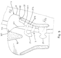
- FIG. 1 illustrates the arrangement of a top stop and a row of teeth on a zipper tape before the installation of a slide according to the present invention.
- FIG. 2 is a top view in an enlarged view of a part of FIG. 1, showing the positioning of the top stop on the zipper tape relative to the first tooth.
- FIG. 3 is a bottom view of FIG. 2 .
- FIG. 4 is similar to FIG. 2 but showing the springy free arm forced downwards.
- FIG. 5 is a bottom plain view in an enlarged scale of the present invention.
- FIG. 6 is a top view of the present invention before insertion of the slide into the gap between the stop block and the first tooth.
- FIG. 7 is similar to FIG. 6 but showing the slide inserted into the gap between the stop block and the first tooth.
- FIG. 8 illustrates the slide inserted into the gap between the stop block and the first tooth and engaged with the zipper tape according to the present invention.
- FIG. 9 is a sectional view in an enlarged scale of a part of the present invention, showing the slide engaged with the row of teeth on the zipper tape and stopped at the top stop.
- FIG. 10 is a plain view of the present invention, showing slide pulled to the upper limited position.
- a top stop 1 is injection-molded on a zipper tape 2 at one end of the row of teeth 21 on a longitudinal side rib of the zipper tape 2 .
- the top stop 1 comprises a stop block 11 .
- the transverse length of the stop block 11 is greater than the length of the teeth 21 .
- the stop block 11 comprises a sloping bottom edge 111 curved inwardly downwards and terminating in a downward bottom projection 1111 , a front stop face 113 at the front side thereof remote from the zipper tape 2 , and a rear stop projection 112 at the rear side thereof on the zipper tape 2 .
- the rear stop projection 112 of the stop block 11 is stopped at a top edge 31 of the slide 3 , and the front stop face 113 of the stop block 11 is stopped at one side 301 of an inside partition wall 30 of the slide 3 , and therefore the slide 3 is stopped from escaping out of the constraint of the top stop 1 .
- the sloping bottom edge 111 of the stop block 11 defines with the topmost edge of the first tooth 21 a gap 4 through which the slide 3 is inserted into engagement with the zipper tape 2 .
- the first tooth 21 is injection-molded on the zipper tape 2 , comprising an upper tooth body 5 and a lower tooth body 6 respectively disposed at top and bottom sides of the zipper tape 2 .
- the upper tooth body 5 comprises a backward opening 213 , and a springy free arm 214 backwardly extended thereof and suspended between the backward opening 213 and the gap 4 (see FIGS. 2 and 4 ).
- the lower tooth body 6 comprises a sloping top edge 2101 sloping backwardly downwards and defining with the sloping bottom edge 111 of the stop block 11 a part of the gap 4 (see FIGS. 3 and 5 ).
- the springy free arm 214 When inserting the slide 2 through the gap 4 into engagement with the zipper tape 2 , the springy free arm 214 is forced downwards toward the inside of the backward opening 213 (see the imaginary line shown in FIG. 4) to broaden the gap 4 , enabling the slide 3 to be positively moved along the sloping top edge 2101 of the lower tooth body 6 into engagement with the zipper tape 2 . After installation of the slide 3 , the springy free arm 214 immediately returns to its former shape to stop the slide 3 from backward movement.
- the shape of the upper part of the stop block 11 is not exactly identical to the lower part of the stop block 11 .
- the length of the upper part of the downward bottom projection 1111 at the top side of the zipper tape 2 is relatively shorter than the length of the lower part of the downward bottom projection 1111 at the bottom side of the zipper tape 2 , that is, the vertical distance between the downward bottom projection 1111 of the stop block 11 and the springy free arm 214 of the upper tooth body 5 of the first tooth 21 is relatively greater than the vertical distance between the downward bottom projection 1111 of the stop block 11 and the topmost point of the sloping top edge 2101 of the lower tooth body 6 of the first tooth 21 .
- This design enables the slide 3 to be easily and positively moved into engagement with the zipper tape 2 .
Landscapes
- Slide Fasteners (AREA)
Abstract
A zipper teeth and top stop arrangement includes a zipper tape, a row of teeth injection-molded on the zipper tape, a slide sliding on the row of teeth, and a top stop injection-molded on the zipper tape and space from a first tooth of the row of teeth by a gap for stopping the sliding from escaping out of engagement with the zipper tape, wherein the first tooth of the row of teeth has an upper tooth body and a lower tooth body respectively disposed at top and bottom side of the zipper tape, the upper tooth body having a backward opening and a springy free arm suspended between the backward opening and the gap to stop the slide from escaping out of engagement with the zipper tape, the springy free arm being forced downwards by the slide for enabling the slide to be moved into engagement with the zipper tape during installation, the lower tooth body having a sloping top edge sloping backwardly downwards for guiding the slide into engagement with the zipper tape during installation of the slide in the zipper tape.
Description
The present invention relates to zippers, and more specifically to a zipper teeth and top stop arrangement for zipper, which enables the slide to be quickly and positively installed, and prevents the slide from escaping out of the zipper tape after installation.
Various top stop and zipper teeth arrangements have been disclosed. Exemplars are seen in U.S. Pat. Nos. 5,860,193 and 6,070,306. The designs shown in U.S. Pat. Nos. 5,860,193 and 6,070,306 are functional, however much effort should be employed during installation of the slide in the zipper tape.
It is the main object of the present invention to provide a zipper teeth and top stop arrangement for zipper, which enables the slide to be easily and positively inserted into position during its installation. It is another object of the present invention to provide a zipper teeth and top stop arrangement for zipper, which prevents the slide from escaping out of engagement with the zipper tape after its installation. According to the present invention, the first tooth of the row of teeth on the zipper tape comprises an upper tooth body and a lower tooth body respectively disposed at top and bottom sides of the zipper tape. The upper tooth body has a backward opening, and a springy free arm suspended between the backward opening and the top stop. The springy free arm is forced downward to broaden the gap between the top stop and the first tooth for enabling the slide to be easily inserted into position during installation of the slide. The springy free arm immediately returns to its former shape after installation of the slide, preventing the slide from backward movement. The lower tooth body has a sloping top edge sloping backwardly downwards for guiding the slide into engagement with the zipper taper during installation of the slide in the zipper tape.
FIG. 1 illustrates the arrangement of a top stop and a row of teeth on a zipper tape before the installation of a slide according to the present invention.
FIG. 2 is a top view in an enlarged view of a part of FIG. 1, showing the positioning of the top stop on the zipper tape relative to the first tooth.
FIG. 3 is a bottom view of FIG. 2.
FIG. 4 is similar to FIG. 2 but showing the springy free arm forced downwards.
FIG. 5 is a bottom plain view in an enlarged scale of the present invention.
FIG. 6 is a top view of the present invention before insertion of the slide into the gap between the stop block and the first tooth.
FIG. 7 is similar to FIG. 6 but showing the slide inserted into the gap between the stop block and the first tooth.
FIG. 8 illustrates the slide inserted into the gap between the stop block and the first tooth and engaged with the zipper tape according to the present invention.
FIG. 9 is a sectional view in an enlarged scale of a part of the present invention, showing the slide engaged with the row of teeth on the zipper tape and stopped at the top stop.
FIG. 10 is a plain view of the present invention, showing slide pulled to the upper limited position.
Referring to FIG. 1 and FIGS. from 6 through 10, a top stop 1 is injection-molded on a zipper tape 2 at one end of the row of teeth 21 on a longitudinal side rib of the zipper tape 2. The top stop 1 comprises a stop block 11. The transverse length of the stop block 11 is greater than the length of the teeth 21. The stop block 11 comprises a sloping bottom edge 111 curved inwardly downwards and terminating in a downward bottom projection 1111, a front stop face 113 at the front side thereof remote from the zipper tape 2, and a rear stop projection 112 at the rear side thereof on the zipper tape 2. When the slide 3 is pulled to the upper limited position after installation, the rear stop projection 112 of the stop block 11 is stopped at a top edge 31 of the slide 3, and the front stop face 113 of the stop block 11 is stopped at one side 301 of an inside partition wall 30 of the slide 3, and therefore the slide 3 is stopped from escaping out of the constraint of the top stop 1. The sloping bottom edge 111 of the stop block 11 defines with the topmost edge of the first tooth 21 a gap 4 through which the slide 3 is inserted into engagement with the zipper tape 2.
The first tooth 21 is injection-molded on the zipper tape 2, comprising an upper tooth body 5 and a lower tooth body 6 respectively disposed at top and bottom sides of the zipper tape 2. The upper tooth body 5 comprises a backward opening 213, and a springy free arm 214 backwardly extended thereof and suspended between the backward opening 213 and the gap 4 (see FIGS. 2 and 4). The lower tooth body 6 comprises a sloping top edge 2101 sloping backwardly downwards and defining with the sloping bottom edge 111 of the stop block 11 a part of the gap 4 (see FIGS. 3 and 5). When inserting the slide 2 through the gap 4 into engagement with the zipper tape 2, the springy free arm 214 is forced downwards toward the inside of the backward opening 213 (see the imaginary line shown in FIG. 4) to broaden the gap 4, enabling the slide 3 to be positively moved along the sloping top edge 2101 of the lower tooth body 6 into engagement with the zipper tape 2. After installation of the slide 3, the springy free arm 214 immediately returns to its former shape to stop the slide 3 from backward movement.
Further, the shape of the upper part of the stop block 11 is not exactly identical to the lower part of the stop block 11. The length of the upper part of the downward bottom projection 1111 at the top side of the zipper tape 2 is relatively shorter than the length of the lower part of the downward bottom projection 1111 at the bottom side of the zipper tape 2, that is, the vertical distance between the downward bottom projection 1111 of the stop block 11 and the springy free arm 214 of the upper tooth body 5 of the first tooth 21 is relatively greater than the vertical distance between the downward bottom projection 1111 of the stop block 11 and the topmost point of the sloping top edge 2101 of the lower tooth body 6 of the first tooth 21. This design enables the slide 3 to be easily and positively moved into engagement with the zipper tape 2.
Claims (2)
1. A zipper tooth and top stop arrangement comprising a zipper tape having a longitudinal side rib, a plurality of teeth molded on said zipper tape in a row along said longitudinal side rib, a slide sliding on said row of teeth, and a top stop comprising a stop block disposed at said zipper tape and spaced from one end of said row of teeth to stop said slide from escaping out of said row of teeth, said stop block comprising a sloping bottom edge curved inwardly downwards and terminating in a downward bottom projection, a front stop face at a front side thereof remote from said zipper tape, and a rear stop projection at a rear side thereof on said zipper tape, said teeth including a first tooth defining with the sloping bottom edge of said stop block a gap through which said slide is inserted into engagement with said zipper tape,
wherein said first tooth is injection-molded on said zipper tape, comprising an upper tooth body and a lower tooth body respectively disposed at top and bottom sides of said zipper tape, said upper tooth body comprising a backward opening, and a springy free arm backwardly extended thereof and suspended between said backward opening and said gap, said lower tooth body comprising a sloping top edge sloping backwardly downwards and defining with the sloping bottom edge of said stop block a part of said gap.
2. The zipper teeth and top stop arrangement of claim 1 wherein the downward bottom projection of said top stop has an upper part and a lower part respectively disposed at the top and bottom sides of said zipper tape, the upper part of the downward bottom projection of said stop stop being relatively shorter than the lower part of the downward bottom projection thereof.
Priority Applications (1)
| Application Number | Priority Date | Filing Date | Title |
|---|---|---|---|
| US09/592,948 US6327755B1 (en) | 2000-06-13 | 2000-06-13 | Zipper teeth and top stop arrangement for zipper |
Applications Claiming Priority (1)
| Application Number | Priority Date | Filing Date | Title |
|---|---|---|---|
| US09/592,948 US6327755B1 (en) | 2000-06-13 | 2000-06-13 | Zipper teeth and top stop arrangement for zipper |
Publications (1)
| Publication Number | Publication Date |
|---|---|
| US6327755B1 true US6327755B1 (en) | 2001-12-11 |
Family
ID=24372707
Family Applications (1)
| Application Number | Title | Priority Date | Filing Date |
|---|---|---|---|
| US09/592,948 Expired - Fee Related US6327755B1 (en) | 2000-06-13 | 2000-06-13 | Zipper teeth and top stop arrangement for zipper |
Country Status (1)
| Country | Link |
|---|---|
| US (1) | US6327755B1 (en) |
Cited By (8)
| Publication number | Priority date | Publication date | Assignee | Title |
|---|---|---|---|---|
| US6715187B1 (en) * | 2002-11-18 | 2004-04-06 | Wallace Wang | Zip fastener top-end piece arrangement |
| EP1516553A1 (en) * | 2003-09-19 | 2005-03-23 | Ykk Corporation | Top end stop of slide fastener |
| US20050060848A1 (en) * | 2003-09-22 | 2005-03-24 | Chang-Wen Tsaur | Upper stopper structure of zipper |
| US20090049658A1 (en) * | 2005-04-01 | 2009-02-26 | Ykk Corporation | Readily Burstable Slide Fastener |
| US20120017403A1 (en) * | 2010-07-23 | 2012-01-26 | Tsai-Yu Chang | Stop of a zipper |
| US20120170789A1 (en) * | 2010-12-29 | 2012-07-05 | Hon Hai Precision Industry Co., Ltd. | Earphone assembly |
| TWI507050B (en) * | 2011-01-04 | 2015-11-01 | Hon Hai Prec Ind Co Ltd | Earphone assembly |
| US20230232944A1 (en) * | 2020-06-22 | 2023-07-27 | Ykk Europe Limited | Top stop for slide fastener chain and method of disengaging slider from slide fastener |
Citations (6)
| Publication number | Priority date | Publication date | Assignee | Title |
|---|---|---|---|---|
| US2894305A (en) * | 1956-05-08 | 1959-07-14 | Talon Inc | Quick release end stop |
| US4023241A (en) * | 1974-12-28 | 1977-05-17 | Yoshida Kogyo Kabushiki Kaisha | Top end construction for slide fasteners |
| US4858284A (en) * | 1987-04-20 | 1989-08-22 | Yoshida Kogyo K. K. | Separable bottom end stop for slide fastener |
| US5653002A (en) * | 1994-06-27 | 1997-08-05 | Ykk Corporation | Slide fastener |
| US5860193A (en) * | 1998-05-14 | 1999-01-19 | Wang; Wallace | Top stop for a zipper |
| US6070306A (en) * | 1999-11-19 | 2000-06-06 | Wang; Wallace | Stop and zipper teeth arrangement |
-
2000
- 2000-06-13 US US09/592,948 patent/US6327755B1/en not_active Expired - Fee Related
Patent Citations (6)
| Publication number | Priority date | Publication date | Assignee | Title |
|---|---|---|---|---|
| US2894305A (en) * | 1956-05-08 | 1959-07-14 | Talon Inc | Quick release end stop |
| US4023241A (en) * | 1974-12-28 | 1977-05-17 | Yoshida Kogyo Kabushiki Kaisha | Top end construction for slide fasteners |
| US4858284A (en) * | 1987-04-20 | 1989-08-22 | Yoshida Kogyo K. K. | Separable bottom end stop for slide fastener |
| US5653002A (en) * | 1994-06-27 | 1997-08-05 | Ykk Corporation | Slide fastener |
| US5860193A (en) * | 1998-05-14 | 1999-01-19 | Wang; Wallace | Top stop for a zipper |
| US6070306A (en) * | 1999-11-19 | 2000-06-06 | Wang; Wallace | Stop and zipper teeth arrangement |
Cited By (15)
| Publication number | Priority date | Publication date | Assignee | Title |
|---|---|---|---|---|
| US6715187B1 (en) * | 2002-11-18 | 2004-04-06 | Wallace Wang | Zip fastener top-end piece arrangement |
| EP1516553A1 (en) * | 2003-09-19 | 2005-03-23 | Ykk Corporation | Top end stop of slide fastener |
| US20050060847A1 (en) * | 2003-09-19 | 2005-03-24 | Naoyuki Himi | Top end stop of slide fastener |
| US7185400B2 (en) | 2003-09-19 | 2007-03-06 | Ykk Corporation | Top end stop of slide fastener |
| US20050060848A1 (en) * | 2003-09-22 | 2005-03-24 | Chang-Wen Tsaur | Upper stopper structure of zipper |
| US20120011684A1 (en) * | 2005-04-01 | 2012-01-19 | Ykk Corporation | Readily burstable slide fastener |
| US20090049658A1 (en) * | 2005-04-01 | 2009-02-26 | Ykk Corporation | Readily Burstable Slide Fastener |
| US8800118B2 (en) * | 2005-04-01 | 2014-08-12 | Ykk Corporation | Readily burstable slide fastener |
| US8925161B2 (en) * | 2005-04-01 | 2015-01-06 | Ykk Corporation | Readily burstable slide fastener |
| US20120017403A1 (en) * | 2010-07-23 | 2012-01-26 | Tsai-Yu Chang | Stop of a zipper |
| US20120170789A1 (en) * | 2010-12-29 | 2012-07-05 | Hon Hai Precision Industry Co., Ltd. | Earphone assembly |
| US8447062B2 (en) * | 2010-12-29 | 2013-05-21 | Hon Hai Precision Industry Co., Ltd. | Earphone assembly |
| TWI507050B (en) * | 2011-01-04 | 2015-11-01 | Hon Hai Prec Ind Co Ltd | Earphone assembly |
| US20230232944A1 (en) * | 2020-06-22 | 2023-07-27 | Ykk Europe Limited | Top stop for slide fastener chain and method of disengaging slider from slide fastener |
| US12022919B2 (en) * | 2020-06-22 | 2024-07-02 | Ykk Corporation | Top stop for slide fastener chain and method of disengaging slider from slide fastener |
Similar Documents
| Publication | Publication Date | Title |
|---|---|---|
| KR100993644B1 (en) | Reverse opening slide fastener | |
| US6775885B1 (en) | Two way open-end zipper | |
| US6070306A (en) | Stop and zipper teeth arrangement | |
| US6327755B1 (en) | Zipper teeth and top stop arrangement for zipper | |
| JP4632924B2 (en) | Slider for slide fastener with automatic stop device | |
| KR0158097B1 (en) | Slider for slide fastener | |
| CN100571563C (en) | Zipper head with forced locking device | |
| JP3622885B2 (en) | Separation fitting for slider with stop device | |
| ES2234494T3 (en) | ZIPPER CLOSURE PROVIDED WITH A SEPARABLE LOWER TERMINAL BUMPER ASSEMBLY. | |
| GB2318827A (en) | Auto-lock slider for slide fastener | |
| EP0581319B1 (en) | Separable bottom end stop assembly and its assembling and separating method for concealed slide fasteners | |
| MXPA97008157A (en) | Automatic closure slider for cremall closure | |
| EP1400184A3 (en) | A slider for a concealed slide fastener | |
| JP2009022547A (en) | Slider for slide fastener | |
| ITTO20100002A1 (en) | THIN CURSOR FOR LIGHTNING CLOSURES. | |
| US7293334B2 (en) | Integral zipper slide and guard | |
| CN101980627B (en) | Slide fastener opener | |
| US5860193A (en) | Top stop for a zipper | |
| US6715187B1 (en) | Zip fastener top-end piece arrangement | |
| CN203492918U (en) | Puller of zipper | |
| JP4501775B2 (en) | connector | |
| WO2018185928A1 (en) | Slider for slide fastener | |
| EP1869990B1 (en) | A slider for a slide fastener | |
| US5535492A (en) | Automatic lock sliders for slide fasteners | |
| CN111315251B (en) | Slider for slide fastener |
Legal Events
| Date | Code | Title | Description |
|---|---|---|---|
| FEPP | Fee payment procedure |
Free format text: PAYOR NUMBER ASSIGNED (ORIGINAL EVENT CODE: ASPN); ENTITY STATUS OF PATENT OWNER: SMALL ENTITY |
|
| FPAY | Fee payment |
Year of fee payment: 4 |
|
| REMI | Maintenance fee reminder mailed | ||
| LAPS | Lapse for failure to pay maintenance fees | ||
| LAPS | Lapse for failure to pay maintenance fees |
Free format text: PATENT EXPIRED FOR FAILURE TO PAY MAINTENANCE FEES (ORIGINAL EVENT CODE: EXP.); ENTITY STATUS OF PATENT OWNER: SMALL ENTITY |
|
| STCH | Information on status: patent discontinuation |
Free format text: PATENT EXPIRED DUE TO NONPAYMENT OF MAINTENANCE FEES UNDER 37 CFR 1.362 |
|
| FP | Lapsed due to failure to pay maintenance fee |
Effective date: 20091211 |