US631663A - Wagon-jack. - Google Patents
Wagon-jack. Download PDFInfo
- Publication number
- US631663A US631663A US63485797A US1897634857A US631663A US 631663 A US631663 A US 631663A US 63485797 A US63485797 A US 63485797A US 1897634857 A US1897634857 A US 1897634857A US 631663 A US631663 A US 631663A
- Authority
- US
- United States
- Prior art keywords
- support
- wagon
- side plates
- jack
- catch
- Prior art date
- Legal status (The legal status is an assumption and is not a legal conclusion. Google has not performed a legal analysis and makes no representation as to the accuracy of the status listed.)
- Expired - Lifetime
Links
- 150000001875 compounds Chemical class 0.000 description 4
- 230000000994 depressogenic effect Effects 0.000 description 4
- 238000010276 construction Methods 0.000 description 2
- RZVAJINKPMORJF-UHFFFAOYSA-N Acetaminophen Chemical compound CC(=O)NC1=CC=C(O)C=C1 RZVAJINKPMORJF-UHFFFAOYSA-N 0.000 description 1
- 241000534414 Anotopterus nikparini Species 0.000 description 1
- 241001280113 Mycobacterium phage Potter Species 0.000 description 1
- 229910000831 Steel Inorganic materials 0.000 description 1
- 238000005266 casting Methods 0.000 description 1
- 230000000881 depressing effect Effects 0.000 description 1
- 230000003028 elevating effect Effects 0.000 description 1
- UAJUXJSXCLUTNU-UHFFFAOYSA-N pranlukast Chemical compound C=1C=C(OCCCCC=2C=CC=CC=2)C=CC=1C(=O)NC(C=1)=CC=C(C(C=2)=O)C=1OC=2C=1N=NNN=1 UAJUXJSXCLUTNU-UHFFFAOYSA-N 0.000 description 1
- 229960004583 pranlukast Drugs 0.000 description 1
- 230000003014 reinforcing effect Effects 0.000 description 1
- 239000010959 steel Substances 0.000 description 1
Images
Classifications
-
- B—PERFORMING OPERATIONS; TRANSPORTING
- B66—HOISTING; LIFTING; HAULING
- B66F—HOISTING, LIFTING, HAULING OR PUSHING, NOT OTHERWISE PROVIDED FOR, e.g. DEVICES WHICH APPLY A LIFTING OR PUSHING FORCE DIRECTLY TO THE SURFACE OF A LOAD
- B66F15/00—Crowbars or levers
Definitions
- Wagon-jack which is strong, cheap, simple in construction and operation, and has a considerable range of adjustment.
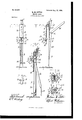
- Figure I is a front elevation of my jack; Fig. II, a side-elevation thereof, showing the support depressed; Fig. III, a vertical section thereof, showing the support elevated.
- Fig. IV is a top plan view of the sliding step.
- Fig.V is an enlarged cross-section on lineV V of Fig. III.
- Fig. VI is an enlarged cross-section on line VI of Fig. III, omitting the sliding step.
- My jack consists of a standard composed of the flattened base 1 and side plates 2 2, secured thereto and connected near their tops by bolt 3. A bit of tubing 30 is strung on bolt to preserve distance between side plates. Between the plates is fitted the support 4, carried on the standard and elevated and depressed thereon by lever to engage with the wagon axle and lift the wheel off the ground.
- This support 4. is formed above with steps 5 and 6, with a central slot 7, with rear ribs 8 8, fitted to the rear of the side plates 2 2, and with a widened front face 9, having integral teeth 10 10 10, formed, as here shown, with horizontal tops and inclined below. Of these steps one, as 6, maybe arranged immediately over side plates of standard and one, as 5, to the rear thereof and reinforced by rib 40.
- a slide or sliding step fitted to the front face-plate 9 and having side jaws 12 12 engaging with the outwardly-extending edges 50, forming front ribs corresponding to rear ribs 8 8 thereof, and a flattened top 13 for engaging with the axle and sustaining the weight of the wagon.
- slot 1 1 in the bottom of said slide is arranged a catch 15, pivotally secured to the slide by pivot 16, which catch is normally held in engagement with one of the teeth 10 by spring 17, arranged between thumb-piece 18 of the catch and the inner surface of the slide. I have shown a good way to hold this spring securely in position by arranging it in engagement with the integral stud 19 on the catch and a depression 20 in the interior of the slide.
- the support is elevated and depressed by means of a compound lever composed of a handle-bar 21, which is a simple flat bar whose end is bent, forming a handle 22, said handle bar being pivotally secured on pin 23 of support 4, and of flat bars 25 25, pivotally connected at 26 to handle-bar 21 and pivotally secured to lug 24. on base.
- This lever operates with power on the principle of the tog- 7o gle-joint to elevate the wagon-wheel from the ground, and when thrown into position shown in Fig. III locks support in upper position, sustaining wagon-wheel 01f the ground.
- the axle of the wagon may rest on one of the steps 5 or 6 or on the sliding step 11, which when the support is depressed in the position shown in Fig. 11 is pushed up by hand to engage with the axle and held there in position by engagement of the catch 15 with one of the teeth 10. From the form of the teeth it will be seen that the slide may be pushed up by hand without touching the catch; but when desired to drop it the catch is withdrawn from engagement with the teeth by pressure on the thumb-piece. The lowest tooth is provided with a pin 27 to prevent the slide from dropping off away from the support.
- my jack is very simple and cheap in construction, it being formed for the most part of castings, the side plates, handle-bar, and flat lever-bars being simple pieces of steel and all the parts being easily assembled without machine-work.
- a metallic wagon-jack the combination of a standard having a flattened base and aportion upwardly extending therefrom, side plates secured thereto, a slotted support fitted to slide between the side plates, said support having a central portion fitting between said side plates and outwardly-extending ribs on its front and rear, engaging with the front and rear edges thereof, said support having a series of integral steps formed at or near its upper end and an integral flange for reinforcing said steps; a bolt connecting the upper ends of said side plates of the standard and a tube strung on said bolt between said side plates, said bolt and tube extending through the slot in the support, a compound lever connected both to said support and to the upwardly-extendin g portion of the standard and handle-bar integral with said compound lever.
- a wagon-jack the combination of a flattened base 1, integral lug 24, side plates 2 2, secured to said base; support 4: supported and sliding on said side plates, steps 5 and 6 integral with said support, a widened front face 9 formed with teeth 10 10 10, also integral therewith; a slidable step 11 having side jaws 12 12 engaging with the side edges of said widened front face, formed with a flattened top 13 and with a slot 14 and depression 20; a catch 15 pivotally secured to said slid able step and arranged in said slot and having an outwardly-extending thumb-piece 18 and an integral stud 19, a spiral spring 17 set in said depression 20 and engaging with said stud 19, a cross-pin 27 secured to the lowest tooth on said support; a compound lever for elevating and depressing said support and spring-catch and a bolt 3 for connecting the upper ends of said side plates 2 2, a tube 50 strung on said bolt for fixing the distance between said side plates, said bolt and tube being arranged in a slot 7 formed in said base; support
Landscapes
- Life Sciences & Earth Sciences (AREA)
- Engineering & Computer Science (AREA)
- Geology (AREA)
- Mechanical Engineering (AREA)
- Structural Engineering (AREA)
- Handcart (AREA)
Description
Patented Aug. 22, I899.
No. 63l,663.
Y w. M POTTER.
WA G 0 N J A C K (Application filed May 3., 1897.)
(No' Model.)
WITNESSES.- il/ [IENTOK 224 ATTORNEY.
UNITED STATES I PATENT OFFICE.
\VILLIAM M. POTTER, OF SYRACUSE, NEW YORK, ASSIGNOR TO E. O.
STEARNS & CO.
WAGON-JAG K.
SPECIFICATION forming part of Letters Patent No. 631,663, dated August 22, 1899.
Application filed May 3, 1897. 'Serial No. 634,857. (No model.)
T at whom it may concern.-
Be it known that I, WILLIAM M. POTTER, a citizen of the United States, re'sidingat Syracuse, in the county of Onondaga and State of New York, have invented a new and useful Improvement in Wagon-Jacks; and I do hereby declare that the following, in connection with the accompanying drawings, is a full, clear, and exact description of the invention.
What I have invented is a new and improved Wagon-jack which is strong, cheap, simple in construction and operation, and has a considerable range of adjustment.
My invention will be understood by reference to the accompanying drawings, in which the same numerals of reference indicate the same parts in all the figures.
Figure I is a front elevation of my jack; Fig. II, a side-elevation thereof, showing the support depressed; Fig. III, a vertical section thereof, showing the support elevated. Fig. IV is a top plan view of the sliding step. Fig.V is an enlarged cross-section on lineV V of Fig. III. Fig. VI is an enlarged cross-section on line VI of Fig. III, omitting the sliding step.
My jack consists of a standard composed of the flattened base 1 and side plates 2 2, secured thereto and connected near their tops by bolt 3. A bit of tubing 30 is strung on bolt to preserve distance between side plates. Between the plates is fitted the support 4, carried on the standard and elevated and depressed thereon by lever to engage with the wagon axle and lift the wheel off the ground. This support 4. is formed above with steps 5 and 6, with a central slot 7, with rear ribs 8 8, fitted to the rear of the side plates 2 2, and with a widened front face 9, having integral teeth 10 10 10, formed, as here shown, with horizontal tops and inclined below. Of these steps one, as 6, maybe arranged immediately over side plates of standard and one, as 5, to the rear thereof and reinforced by rib 40.
11 is a slide or sliding step fitted to the front face-plate 9 and having side jaws 12 12 engaging with the outwardly-extending edges 50, forming front ribs corresponding to rear ribs 8 8 thereof, and a flattened top 13 for engaging with the axle and sustaining the weight of the wagon. In slot 1 1 in the bottom of said slide is arranged a catch 15, pivotally secured to the slide by pivot 16, which catch is normally held in engagement with one of the teeth 10 by spring 17, arranged between thumb-piece 18 of the catch and the inner surface of the slide. I have shown a good way to hold this spring securely in position by arranging it in engagement with the integral stud 19 on the catch and a depression 20 in the interior of the slide.
The support is elevated and depressed by means of a compound lever composed of a handle-bar 21, which is a simple flat bar whose end is bent, forming a handle 22, said handle bar being pivotally secured on pin 23 of support 4, and of flat bars 25 25, pivotally connected at 26 to handle-bar 21 and pivotally secured to lug 24. on base. This lever operates with power on the principle of the tog- 7o gle-joint to elevate the wagon-wheel from the ground, and when thrown into position shown in Fig. III locks support in upper position, sustaining wagon-wheel 01f the ground.
During use the axle of the wagon may rest on one of the steps 5 or 6 or on the sliding step 11, which when the support is depressed in the position shown in Fig. 11 is pushed up by hand to engage with the axle and held there in position by engagement of the catch 15 with one of the teeth 10. From the form of the teeth it will be seen that the slide may be pushed up by hand without touching the catch; but when desired to drop it the catch is withdrawn from engagement with the teeth by pressure on the thumb-piece. The lowest tooth is provided with a pin 27 to prevent the slide from dropping off away from the support. As I have stated, my jack is very simple and cheap in construction, it being formed for the most part of castings, the side plates, handle-bar, and flat lever-bars being simple pieces of steel and all the parts being easily assembled without machine-work.
Having thus fully described my invention, what I claim, and desire to protect by Letters Patent, is
1. In a metallic wagon-jack the combination of a standard having a flattened base and aportion upwardly extending therefrom, side plates secured thereto, a slotted support fitted to slide between the side plates, said support having a central portion fitting between said side plates and outwardly-extending ribs on its front and rear, engaging with the front and rear edges thereof, said support having a series of integral steps formed at or near its upper end and an integral flange for reinforcing said steps; a bolt connecting the upper ends of said side plates of the standard and a tube strung on said bolt between said side plates, said bolt and tube extending through the slot in the support, a compound lever connected both to said support and to the upwardly-extendin g portion of the standard and handle-bar integral with said compound lever.
2. In a wagon-jack, the combination of a flattened base 1, integral lug 24, side plates 2 2, secured to said base; support 4: supported and sliding on said side plates, steps 5 and 6 integral with said support, a widened front face 9 formed with teeth 10 10 10, also integral therewith; a slidable step 11 having side jaws 12 12 engaging with the side edges of said widened front face, formed with a flattened top 13 and with a slot 14 and depression 20; a catch 15 pivotally secured to said slid able step and arranged in said slot and having an outwardly-extending thumb-piece 18 and an integral stud 19, a spiral spring 17 set in said depression 20 and engaging with said stud 19, a cross-pin 27 secured to the lowest tooth on said support; a compound lever for elevating and depressing said support and spring-catch and a bolt 3 for connecting the upper ends of said side plates 2 2, a tube 50 strung on said bolt for fixing the distance between said side plates, said bolt and tube being arranged in a slot 7 formed in said sup port.
In witness whereof I have hereunto set my hand, in the presence of two attesting wit nesses, at Syracuse, in the county of Onon daga, in the State of New York, this 30th day of April, 1897.
WILLIAM M. POTTER. \Vitnessesi L. F. WEIsBURo, C. O. SoHoENEoK.
Priority Applications (1)
| Application Number | Priority Date | Filing Date | Title |
|---|---|---|---|
| US63485797A US631663A (en) | 1897-05-03 | 1897-05-03 | Wagon-jack. |
Applications Claiming Priority (1)
| Application Number | Priority Date | Filing Date | Title |
|---|---|---|---|
| US63485797A US631663A (en) | 1897-05-03 | 1897-05-03 | Wagon-jack. |
Publications (1)
| Publication Number | Publication Date |
|---|---|
| US631663A true US631663A (en) | 1899-08-22 |
Family
ID=2700258
Family Applications (1)
| Application Number | Title | Priority Date | Filing Date |
|---|---|---|---|
| US63485797A Expired - Lifetime US631663A (en) | 1897-05-03 | 1897-05-03 | Wagon-jack. |
Country Status (1)
| Country | Link |
|---|---|
| US (1) | US631663A (en) |
-
1897
- 1897-05-03 US US63485797A patent/US631663A/en not_active Expired - Lifetime
Similar Documents
| Publication | Publication Date | Title |
|---|---|---|
| US631663A (en) | Wagon-jack. | |
| US672152A (en) | Truck. | |
| US470116A (en) | Wagon-jack | |
| US1275381A (en) | Vehicle-jack. | |
| US599923A (en) | Truck | |
| US524701A (en) | Carriage-jack | |
| US1185383A (en) | Warehouse-truck. | |
| US212806A (en) | Improvement in wagon-jacks | |
| US988208A (en) | Attachment for lifting-jacks. | |
| US384705A (en) | Wagon-jack | |
| US296979A (en) | Wagon-jack | |
| US284975A (en) | Lifting-jack | |
| US490293A (en) | Winfield s | |
| US202849A (en) | Improvement in lifting-jacks | |
| US301820A (en) | Self and joseph m | |
| US1175319A (en) | Concrete-form. | |
| US767535A (en) | Lifting-jack. | |
| US154085A (en) | Improvement in lifting-jacks | |
| US920004A (en) | Scale. | |
| US588212A (en) | Lifting-jack | |
| US677920A (en) | Lifting-jack. | |
| US462796A (en) | John green | |
| US610651A (en) | Lifting-jack | |
| US922474A (en) | Wagon-jack. | |
| US360116A (en) | secco |