US6294763B1 - Apparatus for annealing welded parts and method therefor - Google Patents
Apparatus for annealing welded parts and method therefor Download PDFInfo
- Publication number
- US6294763B1 US6294763B1 US09/460,431 US46043199A US6294763B1 US 6294763 B1 US6294763 B1 US 6294763B1 US 46043199 A US46043199 A US 46043199A US 6294763 B1 US6294763 B1 US 6294763B1
- Authority
- US
- United States
- Prior art keywords
- welded parts
- carriage
- annealing
- annealing furnace
- vertical
- Prior art date
- Legal status (The legal status is an assumption and is not a legal conclusion. Google has not performed a legal analysis and makes no representation as to the accuracy of the status listed.)
- Expired - Fee Related
Links
Images

Classifications
-
- F—MECHANICAL ENGINEERING; LIGHTING; HEATING; WEAPONS; BLASTING
- F27—FURNACES; KILNS; OVENS; RETORTS
- F27B—FURNACES, KILNS, OVENS, OR RETORTS IN GENERAL; OPEN SINTERING OR LIKE APPARATUS
- F27B9/00—Furnaces through which the charge is moved mechanically, e.g. of tunnel type; Similar furnaces in which the charge moves by gravity
- F27B9/14—Furnaces through which the charge is moved mechanically, e.g. of tunnel type; Similar furnaces in which the charge moves by gravity characterised by the path of the charge during treatment; characterised by the means by which the charge is moved during treatment
-
- F—MECHANICAL ENGINEERING; LIGHTING; HEATING; WEAPONS; BLASTING
- F26—DRYING
- F26B—DRYING SOLID MATERIALS OR OBJECTS BY REMOVING LIQUID THEREFROM
- F26B15/00—Machines or apparatus for drying objects with progressive movement; Machines or apparatus with progressive movement for drying batches of material in compact form
- F26B15/10—Machines or apparatus for drying objects with progressive movement; Machines or apparatus with progressive movement for drying batches of material in compact form with movement in a path composed of one or more straight lines, e.g. compound, the movement being in alternate horizontal and vertical directions
-
- F—MECHANICAL ENGINEERING; LIGHTING; HEATING; WEAPONS; BLASTING
- F26—DRYING
- F26B—DRYING SOLID MATERIALS OR OBJECTS BY REMOVING LIQUID THEREFROM
- F26B3/00—Drying solid materials or objects by processes involving the application of heat
- F26B3/28—Drying solid materials or objects by processes involving the application of heat by radiation, e.g. from the sun
- F26B3/283—Drying solid materials or objects by processes involving the application of heat by radiation, e.g. from the sun in combination with convection
-
- F—MECHANICAL ENGINEERING; LIGHTING; HEATING; WEAPONS; BLASTING
- F27—FURNACES; KILNS; OVENS; RETORTS
- F27B—FURNACES, KILNS, OVENS, OR RETORTS IN GENERAL; OPEN SINTERING OR LIKE APPARATUS
- F27B9/00—Furnaces through which the charge is moved mechanically, e.g. of tunnel type; Similar furnaces in which the charge moves by gravity
- F27B9/02—Furnaces through which the charge is moved mechanically, e.g. of tunnel type; Similar furnaces in which the charge moves by gravity of multiple-track type; of multiple-chamber type; Combinations of furnaces
- F27B9/021—Furnaces through which the charge is moved mechanically, e.g. of tunnel type; Similar furnaces in which the charge moves by gravity of multiple-track type; of multiple-chamber type; Combinations of furnaces having two or more parallel tracks
- F27B9/022—With two tracks moving in opposite directions
- F27B9/023—With two tracks moving in opposite directions with a U turn at one end
- F27B9/024—With two tracks moving in opposite directions with a U turn at one end with superimposed tracks
-
- F—MECHANICAL ENGINEERING; LIGHTING; HEATING; WEAPONS; BLASTING
- F27—FURNACES; KILNS; OVENS; RETORTS
- F27B—FURNACES, KILNS, OVENS, OR RETORTS IN GENERAL; OPEN SINTERING OR LIKE APPARATUS
- F27B9/00—Furnaces through which the charge is moved mechanically, e.g. of tunnel type; Similar furnaces in which the charge moves by gravity
- F27B9/06—Furnaces through which the charge is moved mechanically, e.g. of tunnel type; Similar furnaces in which the charge moves by gravity heated without contact between combustion gases and charge; electrically heated
- F27B9/062—Furnaces through which the charge is moved mechanically, e.g. of tunnel type; Similar furnaces in which the charge moves by gravity heated without contact between combustion gases and charge; electrically heated electrically heated
- F27B9/063—Resistor heating, e.g. with resistors also emitting IR rays
- F27B9/065—Resistor heating, e.g. with resistors also emitting IR rays the resistance being transported by the conveyor
-
- F—MECHANICAL ENGINEERING; LIGHTING; HEATING; WEAPONS; BLASTING
- F27—FURNACES; KILNS; OVENS; RETORTS
- F27D—DETAILS OR ACCESSORIES OF FURNACES, KILNS, OVENS, OR RETORTS, IN SO FAR AS THEY ARE OF KINDS OCCURRING IN MORE THAN ONE KIND OF FURNACE
- F27D7/00—Forming, maintaining, or circulating atmospheres in heating chambers
- F27D7/04—Circulating atmospheres by mechanical means
- F27D2007/045—Fans
Definitions
- the present invention relates to an annealing apparatus and an annealing method, particularly with respect to a technique for preventing the temperature from rising locally in a closed space so as to make the temperature in an annealing furnace uniform, and thus, improve the annealing (distortion-eliminating) efficiency.
- FIG. 2 is a schematically plan view showing the outline of such an annealing furnace a.
- Welded parts b, b, . . . are introduced into the annealing furnace a through a doorway c, and mounted on trays d, d, . . . , respectively, and moved in the direction of the arrow by a not-shown carriage means. While the welded parts mounted on the trays d, d, . . .
- the welded parts are heated by not-shown infrared lamps, kept at a predetermined temperature for a time not shorter than a predetermined time to be annealed, and then extracted from the doorway c.
- the apparatus for annealing welded parts of the present invention includes: an annealing furnace which is substantially closed; a doorway through which welded parts are placed into and out of the annealing furnace; a carriage means for carrying welded parts on a predetermined course in the annealing furnace; infrared lamps for heating welded parts carried in the annealing furnace; and a circulating mechanism for circulating hot air in the annealing furnace.
- circulation in the annealing furnace is performed by the circulating mechanism, so that there is no fear that the temperature rises only locally in the annealing furnace. It is therefore, possible to make the temperature in the annealing furnace uniform, so as to prevent welded parts from a thermal deformation caused by an unexpected temperature rise in the annealing furnace.
- an annealing method wherein welded parts are carried from an inlet to an outlet in a substantially closed space while the welded parts are heated by infrared rays so that the welded parts are kept at a predetermined temperature for a time not shorter than a predetermined time, while hot air in the closed space is circulated.
- hot air in the closed space is circulated so that there is no fear that the temperature rises only locally in the closed space. It is therefore, possible to make the temperature in the annealing furnace uniform, so as to prevent welded parts from a thermal deformation caused by an unexpected temperature rise in the closed space.
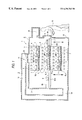
- FIG. 1 shows a schematically longitudinally sectional view of an embodiment of an apparatus for annealing welded parts according to the present invention.
- FIG. 2 shows a schematically plan view of an example of an apparatus for annealing welded parts, according to the prior art.
- An annealing apparatus 1 has an annealing furnace 2 (see FIG. 1 ).
- An outer shell portion 3 of the annealing furnace 2 is formed of an iron plate laminated with a not-shown heat insulating material so that the heat inside the annealing furnace 2 is not conducted to the outside.
- a doorway 5 through which welded parts (for example, welded parts of a lamp body and a lens) 4 are placed in/out of the furnace 2 is formed in one side of the outer shell 3 .
- the doorway 5 can be opened and closed by a door 5 a.
- a carriage means 6 such as a conveyor belt or conveying rollers, for carrying the welded parts 4 , 4 , . . . on a predetermined course, is disposed in the annealing furnace 2 .
- the carriage means 6 has horizontal carriage means 6 L b , 6 L m , and 6 L t , such as a conveyor belt or conveying rollers, for carrying the welded parts 4 , 4 , . . . horizontally, and vertical carriage means 6 V b and 6 V f , such as a lift or elevator mechanism, for carrying the welded parts 4 , 4 , . . . vertically.
- Each of the vertical carriage means 6 V b , 6 V f is an elevator elevated by a not-shown elevating mechanism.
- Two vertical carriage means 6 V f and 6 V b are each disposed on the front side which is on the doorway 5 side, and on the back side which is on the opposite side to the doorway 5 , respectively.
- Each horizontal carriage means 6 L b , 6 L m , 6 L t includes a roller conveyor extending from the front side to the back side of the furnace 2 .
- the three horizontal carriage means 6 L b , 6 L m , and 6 L t are disposed vertically in three stages of a top stage, a middle stage and a bottom stage, respectively.
- a plurality of trays 7 , 7 , . . . are mounted on each of the horizontal carriage means 6 L t , 6 L m , and 6 L b , so as to be disposed in the carrying direction thereof.
- only one tray 7 is mounted on each of the two vertical carriage means 6 V f and 6 V b .
- No tray 7 is mounted on the back-side vertical carriage means 6 V b before the first one of the welded parts 4 is placed in the furnace 2 .
- a pushing-out cylinder 8 f is disposed in a position opposite to the front end of the top-stage horizontal carriage means 6 L t
- a pushing-out cylinder 8 b is disposed on the back-side vertical carriage means 6 v b.
- a large number of infrared lamps 9 , 9 , . . . are disposed above the respective horizontal carriage means 6 L t , 6 L m , and 6 L .
- a circulating fan 11 is disposed in the upper portion 3 a which is a connection port of the duct 10 with the annealing furnace 2 , so that a circulating mechanism 12 is formed. Circulation of the air in the duct 10 by means of the circulating fan 11 may be performed either from the upper portion 3 a to the lower portion 3 b , or from the lower portion 3 b to the upper portion 3 a.
- the welded parts 4 are annealed according to the operation as follows.
- the welded parts 4 are mounted by a worker 13 onto the tray 7 on the vertical carriage means 6 V f , in the condition that the vertical carriage means 6 V f is located in the position corresponding to the doorway 5 (it is also the position corresponding to the middle-stage horizontal carriage means 6 L m ).
- the vertical carriage means 6 V f moves up to a position corresponding to the top-stage horizontal carriage means 6 L t . Then, since the back-side vertical carriage means 6 V b and the front-side vertical carriage means 6 V f are configured to move up/down synchronously, the back-side vertical carriage means 6 V b is located in a position corresponding to the back-side end of the top-stage horizontal carriage means 6 L t when the front-side vertical carriage means 6 V f comes to a position corresponding to the front-side end of the top-stage horizontal carriage means 6 L t.
- the pushing-out cylinder 8 f operates to push out the tray 7 mounted on the front-side vertical carriage means 6 V f toward the horizontal carriage means 6 L t . Then, the tray 7 on the front-side vertical carriage means 6 V f moves to the front-side end of the horizontal carriage means 6 L t , while the tray 7 mounted on the back-side end of the horizontal carriage means 6 L t is pushed out by the movement by the other trays 7 , 7 , . . . on the horizontal carriage means 6 L t , so that the tray 7 on the back-side end of the horizontal carriage means 6 L t moves onto the back-side vertical carriage means 6 V b.
- the vertical carriage means 6 V f and 6 V b move down to middle-stage positions corresponding to the level of the middle-stage horizontal carriage means 6 L m .
- the back-side pushing-out cylinder 8 b operates to push-out the tray 7 mounted on the back-side vertical carriage means 6 V b to the back-side end of the middle-stage horizontal carriage means 6 L m .
- the tray 7 mounted on the back-side vertical carriage means 6 V b moves onto the back-side end of the middle-stage horizontal carriage means 6 L m
- the tray 7 mounted on the front-side end of the horizontal carriage means 6 L m is pushed out by other trays 7 , 7 , . . . on the horizontal carriage means 6 L m forward, so as to move onto the front-side vertical carriage means 6 V f.
- the worker 13 opens the door 5 a , extracts the annealed welded parts 4 mounted on the tray 7 on the front-side vertical carriage means 6 V f , puts new welded parts 4 on the tray 7 on the vertical carriage means 6 V f , and closes the door 5 a.
- the vertical carriage means 6 V f and 6 V b move up to positions corresponding to the top-stage horizontal carriage means 6 L t .
- the tray 7 on the front-side vertical carriage means 6 V f moves onto the horizontal carriage means 6 L t while the tray 7 mounted on the back-side end of the horizontal carriage means 6 L t moves onto the back-side vertical carriage means 6 V b.
- the vertical carriage means 6 V f and 6 V b move down to positions corresponding to the bottom-stage horizontal carriage means 6 L b .
- the back-side pushing-out cylinder 8 b operates to push-out the tray 7 mounted on the back-side vertical carriage means 6 V b toward the back-side end of the bottom-stage horizontal carriage means 6 L b .
- the tray 7 mounted on the back-side vertical carriage means 6 V b moves onto the back-side end of the bottom-stage horizontal carriage means 6 L b while the tray 7 mounted on the front-side end of the horizontal carriage means 6 L b is pushed out by other trays 7 , 7 , . . . on the horizontal carriage means 6 L b so as to move forward onto the front-side vertical carriage means 6 V f.
- the vertical carriage means 6 V f and 6 V b move up to middle-stage positions.
- the worker 13 opens the door 5 a , extracts the annealed welded parts 4 mounted on the tray 7 on the front-side vertical carriage means 6 V f , puts new welded parts 4 onto the tray 7 on the vertical carriage means 6 V f , and closes the door 5 a.
- the vertical carriage means 6 V f and 6 V b move up to top-stage positions.
- the welded parts 4 are annealed while being carried alternately on the course of: the doorway 5 a ⁇ the top-stage horizontal carriage means 6 L t ⁇ the middle-stage horizontal carriage means 6 L m ⁇ the doorway 5 a and on the course of the doorway 5 a ⁇ the top-stage horizontal carriage means 6 L t ⁇ the bottom-stage horizontal carriage means 6 L b ⁇ the doorway 5 a ; in the order of being thrown into the annealing furnace 2 .
- the hot air in the annealing furnace 2 is circulated by the circulating mechanism 12 so that the temperature in the annealing furnace 2 is averaged.
- the temperature in the annealing furnace 2 is monitored by a not-shown temperature sensor.
- the sensor turns the infrared lamps 9 , 9 , . . . off when the temperature in the annealing furnace 2 rises too high, and the sensor turns the infrared lamps 9 , 9 , . . . on when the temperature in the annealing furnace 2 drops too low.
- the temperature in the annealing furnace 2 can be made more uniform.
- the air in the annealing furnace 2 is circulated by the circulating mechanism 12 so that there is no fear that the temperature rises only locally in the closed space. Accordingly, it is possible to make the temperature in the annealing furnace 2 uniform, so that the welded parts 4 , 4 , . . . are prevented from thermal deformation caused by an unexpected temperature rise in the closed space. Therefore, the failure ratio of annealing can be reduced.
- the carriage course of the welded parts 4 is arranged vertically, so that it is possible to save space for installation of the annealing apparatus 1 .
- the apparatus for annealing welded parts includes: an annealing furnace which is substantially closed; a doorway through which welded parts are placed into and out of the annealing furnace; a carriage means for carrying welded parts on a predetermined course in the annealing furnace; infrared lamps for heating welded parts carried in the annealing furnace; and a circulating mechanism for circulating hot air in the annealing furnace.
- circulation in the annealing furnace is performed by the circulating mechanism, so that there is no fear that the temperature rises only locally in the annealing furnace. It is therefore, possible to make the temperature in the annealing furnace uniform, so as to avoid welded parts from a thermal deformation caused by an unexpected temperature rise in the annealing furnace.
- the circulating mechanism in addition to the circulating fan, includes a duct connecting upper and lower portions of the annealing furnace to each other. Accordingly, it is possible to make the temperature in the annealing furnace uniform, efficiently.
- the carriage course of the welded parts is arranged vertically, so that it is possible to save space for installation of the annealing apparatus 1 .
- an annealing method wherein welded parts are carried from an inlet to an outlet in a substantially closed space while the welded parts are heated by infrared rays so that the welded parts are kept at a predetermined temperature for a time not shorter than a predetermined length of time, while hot air in the closed space is circulated.
- hot air in the closed space is circulated so that there is no fear that the temperature rises only locally in the closed space. It is therefore, possible to make the temperature in the annealing furnace uniform, so that it is possible to prevent welded parts from a thermal deformation caused by an unexpected temperature rise in the closed space.
Abstract
To prevent the temperature from rising locally in a closed space so as to make the temperature in an annealing furnace uniform, an apparatus and method for annealing welded parts includes an annealing furnace 2 which is substantially closed; a doorway 5 through which welded parts 4 are placed into and out of the annealing furnace; a carriage mechanism 6 for carrying welded parts on a predetermined course in the annealing furnace; infrared lamps 9 for heating welded parts carried in the annealing furnace; and a circulating mechanism 12 for circulating hot air in the annealing furnace. Thus, the annealing (distortion-eliminating) efficiency of the welded parts is improved.
Description
The present invention relates to an annealing apparatus and an annealing method, particularly with respect to a technique for preventing the temperature from rising locally in a closed space so as to make the temperature in an annealing furnace uniform, and thus, improve the annealing (distortion-eliminating) efficiency.
Stress remains inside synthetic resin parts welded by a welding mechanism such as a hot plate welding method, a vibration welding method, or the like, due to heat applied to the synthetic resin parts at the time of welding. It is therefore, necessary to keep the synthetic resin parts at a predetermined temperature for a time not shorter than a predetermined time, to thereby eliminate the residual stress.
Thus, there exists a prior art technique in which welded parts are carried on a predetermined course in a substantially closed annealing furnace while being heated at a predetermined temperature for a predetermined time in order to eliminate residual stress.
For example, a prior art steam annealing furnace for annealing welded parts with hot air is known. However, the problem with this prior art device is that the heating efficiency was insufficient, so that it took too much time to anneal.
Thus, an annealing furnace using infrared lamps having a superior efficiency of heating is used in the prior art. FIG. 2 is a schematically plan view showing the outline of such an annealing furnace a. Welded parts b, b, . . . are introduced into the annealing furnace a through a doorway c, and mounted on trays d, d, . . . , respectively, and moved in the direction of the arrow by a not-shown carriage means. While the welded parts mounted on the trays d, d, . . . make a round in the annealing furnace a, the welded parts are heated by not-shown infrared lamps, kept at a predetermined temperature for a time not shorter than a predetermined time to be annealed, and then extracted from the doorway c.
However, in the above-mentioned prior art annealing apparatus, there was a problem that welded parts b close to the infrared lamp rose too high in temperature to thermally deform when the doorway c was left closed for a long time for some reasons, for example, because a worker left his/her position.
In addition, in the above-mentioned annealing apparatus, there was a problem that a large plane space was required for installation of the annealing furnace a because the trays d, d, . . . moved in plane in the annealing furnace a.
Taking the foregoing circumstances into consideration, it is therefore an object of the present invention to prevent a temperature from rising locally in a closed space so as to make the temperature in an annealing furnace uniform, to thereby improve the annealing efficiency.
In order to achieve the above object, the apparatus for annealing welded parts of the present invention includes: an annealing furnace which is substantially closed; a doorway through which welded parts are placed into and out of the annealing furnace; a carriage means for carrying welded parts on a predetermined course in the annealing furnace; infrared lamps for heating welded parts carried in the annealing furnace; and a circulating mechanism for circulating hot air in the annealing furnace.
Accordingly, in the apparatus for annealing welded parts according to the present invention, circulation in the annealing furnace is performed by the circulating mechanism, so that there is no fear that the temperature rises only locally in the annealing furnace. It is therefore, possible to make the temperature in the annealing furnace uniform, so as to prevent welded parts from a thermal deformation caused by an unexpected temperature rise in the annealing furnace.
Further, there is provided an annealing method wherein welded parts are carried from an inlet to an outlet in a substantially closed space while the welded parts are heated by infrared rays so that the welded parts are kept at a predetermined temperature for a time not shorter than a predetermined time, while hot air in the closed space is circulated.
Accordingly, in the method for annealing welded parts according to the present invention, hot air in the closed space is circulated so that there is no fear that the temperature rises only locally in the closed space. It is therefore, possible to make the temperature in the annealing furnace uniform, so as to prevent welded parts from a thermal deformation caused by an unexpected temperature rise in the closed space.
FIG. 1 shows a schematically longitudinally sectional view of an embodiment of an apparatus for annealing welded parts according to the present invention.
FIG. 2 shows a schematically plan view of an example of an apparatus for annealing welded parts, according to the prior art.
An embodiment of an annealing apparatus and an annealing method according to the present invention will be described below with reference to the accompanying drawings. In the embodiment shown in the accompanying drawings, the present invention is applied to an apparatus and a method for annealing synthetic resin parts in a car lamp.
An annealing apparatus 1 has an annealing furnace 2 (see FIG. 1). An outer shell portion 3 of the annealing furnace 2 is formed of an iron plate laminated with a not-shown heat insulating material so that the heat inside the annealing furnace 2 is not conducted to the outside. A doorway 5 through which welded parts (for example, welded parts of a lamp body and a lens) 4 are placed in/out of the furnace 2 is formed in one side of the outer shell 3. The doorway 5 can be opened and closed by a door 5 a.
A carriage means 6, such as a conveyor belt or conveying rollers, for carrying the welded parts 4, 4, . . . on a predetermined course, is disposed in the annealing furnace 2. The carriage means 6 has horizontal carriage means 6Lb, 6Lm, and 6Lt, such as a conveyor belt or conveying rollers, for carrying the welded parts 4, 4, . . . horizontally, and vertical carriage means 6Vb and 6Vf, such as a lift or elevator mechanism, for carrying the welded parts 4, 4, . . . vertically.
Each of the vertical carriage means 6Vb, 6Vf, is an elevator elevated by a not-shown elevating mechanism. Two vertical carriage means 6Vf and 6Vb are each disposed on the front side which is on the doorway 5 side, and on the back side which is on the opposite side to the doorway 5, respectively. Each horizontal carriage means 6Lb, 6Lm, 6Lt, includes a roller conveyor extending from the front side to the back side of the furnace 2. The three horizontal carriage means 6Lb, 6Lm, and 6Lt, are disposed vertically in three stages of a top stage, a middle stage and a bottom stage, respectively.
A plurality of trays 7, 7, . . . are mounted on each of the horizontal carriage means 6Lt, 6Lm, and 6Lb, so as to be disposed in the carrying direction thereof. On the other hand, only one tray 7 is mounted on each of the two vertical carriage means 6Vf and 6Vb. No tray 7 is mounted on the back-side vertical carriage means 6Vb before the first one of the welded parts 4 is placed in the furnace 2.
In addition, a pushing-out cylinder 8 f is disposed in a position opposite to the front end of the top-stage horizontal carriage means 6Lt, and a pushing-out cylinder 8 b is disposed on the back-side vertical carriage means 6vb.
A large number of infrared lamps 9, 9, . . . are disposed above the respective horizontal carriage means 6Lt, 6Lm, and 6L.
When a substantially upper-end central portion 3 a and a lower portion 3 b of the outer shell portion 3 of the anneal furnace 2 are connected through a duct 10, a circulating fan 11 is disposed in the upper portion 3 a which is a connection port of the duct 10 with the annealing furnace 2, so that a circulating mechanism 12 is formed. Circulation of the air in the duct 10 by means of the circulating fan 11 may be performed either from the upper portion 3 a to the lower portion 3 b, or from the lower portion 3 b to the upper portion 3 a.
Thus, the welded parts 4 are annealed according to the operation as follows.
The welded parts 4 are mounted by a worker 13 onto the tray 7 on the vertical carriage means 6Vf, in the condition that the vertical carriage means 6Vf is located in the position corresponding to the doorway 5 (it is also the position corresponding to the middle-stage horizontal carriage means 6Lm).
When the door 5 a of the doorway 5 is closed, the vertical carriage means 6Vf moves up to a position corresponding to the top-stage horizontal carriage means 6Lt. Then, since the back-side vertical carriage means 6Vb and the front-side vertical carriage means 6Vf are configured to move up/down synchronously, the back-side vertical carriage means 6Vb is located in a position corresponding to the back-side end of the top-stage horizontal carriage means 6Lt when the front-side vertical carriage means 6Vf comes to a position corresponding to the front-side end of the top-stage horizontal carriage means 6Lt.
At that time, the pushing-out cylinder 8 f operates to push out the tray 7 mounted on the front-side vertical carriage means 6Vf toward the horizontal carriage means 6Lt. Then, the tray 7 on the front-side vertical carriage means 6Vf moves to the front-side end of the horizontal carriage means 6Lt, while the tray 7 mounted on the back-side end of the horizontal carriage means 6Lt is pushed out by the movement by the other trays 7, 7, . . . on the horizontal carriage means 6Lt, so that the tray 7 on the back-side end of the horizontal carriage means 6Lt moves onto the back-side vertical carriage means 6Vb.
Next, the vertical carriage means 6Vf and 6Vb move down to middle-stage positions corresponding to the level of the middle-stage horizontal carriage means 6Lm. Then, the back-side pushing-out cylinder 8 b operates to push-out the tray 7 mounted on the back-side vertical carriage means 6Vb to the back-side end of the middle-stage horizontal carriage means 6Lm. As a result, the tray 7 mounted on the back-side vertical carriage means 6Vb moves onto the back-side end of the middle-stage horizontal carriage means 6Lm, while the tray 7 mounted on the front-side end of the horizontal carriage means 6Lm is pushed out by other trays 7, 7, . . . on the horizontal carriage means 6Lm forward, so as to move onto the front-side vertical carriage means 6Vf.
Then, the worker 13 opens the door 5 a, extracts the annealed welded parts 4 mounted on the tray 7 on the front-side vertical carriage means 6Vf, puts new welded parts 4 on the tray 7 on the vertical carriage means 6Vf, and closes the door 5 a.
Then, the vertical carriage means 6Vf and 6Vb move up to positions corresponding to the top-stage horizontal carriage means 6Lt. Then, in the same manner as mentioned above, the tray 7 on the front-side vertical carriage means 6Vf moves onto the horizontal carriage means 6Lt while the tray 7 mounted on the back-side end of the horizontal carriage means 6Lt moves onto the back-side vertical carriage means 6Vb.
Next, the vertical carriage means 6Vf and 6Vb move down to positions corresponding to the bottom-stage horizontal carriage means 6Lb. Then, the back-side pushing-out cylinder 8 b operates to push-out the tray 7 mounted on the back-side vertical carriage means 6Vb toward the back-side end of the bottom-stage horizontal carriage means 6Lb. As a result, the tray 7 mounted on the back-side vertical carriage means 6Vb moves onto the back-side end of the bottom-stage horizontal carriage means 6Lb while the tray 7 mounted on the front-side end of the horizontal carriage means 6Lb is pushed out by other trays 7, 7, . . . on the horizontal carriage means 6Lb so as to move forward onto the front-side vertical carriage means 6Vf.
Then, the vertical carriage means 6Vf and 6Vb move up to middle-stage positions. Thus, the worker 13 opens the door 5 a, extracts the annealed welded parts 4 mounted on the tray 7 on the front-side vertical carriage means 6Vf, puts new welded parts 4 onto the tray 7 on the vertical carriage means 6Vf, and closes the door 5 a.
Then, the vertical carriage means 6Vf and 6Vb move up to top-stage positions.
In the above-mentioned manner, the welded parts 4 are annealed while being carried alternately on the course of: the doorway 5 a→the top-stage horizontal carriage means 6Lt→the middle-stage horizontal carriage means 6Lm→the doorway 5 a and on the course of the doorway 5 a→the top-stage horizontal carriage means 6Lt→the bottom-stage horizontal carriage means 6Lb→the doorway 5 a; in the order of being thrown into the annealing furnace 2.
The hot air in the annealing furnace 2 is circulated by the circulating mechanism 12 so that the temperature in the annealing furnace 2 is averaged.
That is, when the circulating fan 11 of the circulating mechanism 12 rotates, the air circulates in the annealing furnace 2 and the duct 10, so that the temperature in the annealing furnace 2 is made uniform.
In addition, the temperature in the annealing furnace 2 is monitored by a not-shown temperature sensor. The sensor turns the infrared lamps 9, 9, . . . off when the temperature in the annealing furnace 2 rises too high, and the sensor turns the infrared lamps 9, 9, . . . on when the temperature in the annealing furnace 2 drops too low.
If an air outlet and an air inlet are provided in the annealing furnace 2 and the above-mentioned sensor controls opening/closing of the outlet and inlet, the temperature in the annealing furnace 2 can be made more uniform.
In the above-mentioned annealing apparatus 1, the air in the annealing furnace 2 is circulated by the circulating mechanism 12 so that there is no fear that the temperature rises only locally in the closed space. Accordingly, it is possible to make the temperature in the annealing furnace 2 uniform, so that the welded parts 4, 4, . . . are prevented from thermal deformation caused by an unexpected temperature rise in the closed space. Therefore, the failure ratio of annealing can be reduced.
In addition, the carriage course of the welded parts 4 is arranged vertically, so that it is possible to save space for installation of the annealing apparatus 1.
The shape and structure of each part shown in the above-mentioned embodiment merely show a specific example for carrying out the present invention. The technical scope of the present invention should not be interpreted in a limited fashion by these shapes and structures.
As will be clearly understood from the above description, according to the present invention, the apparatus for annealing welded parts includes: an annealing furnace which is substantially closed; a doorway through which welded parts are placed into and out of the annealing furnace; a carriage means for carrying welded parts on a predetermined course in the annealing furnace; infrared lamps for heating welded parts carried in the annealing furnace; and a circulating mechanism for circulating hot air in the annealing furnace.
Accordingly, in the apparatus for annealing welded parts according to the present invention, circulation in the annealing furnace is performed by the circulating mechanism, so that there is no fear that the temperature rises only locally in the annealing furnace. It is therefore, possible to make the temperature in the annealing furnace uniform, so as to avoid welded parts from a thermal deformation caused by an unexpected temperature rise in the annealing furnace.
In the present invention, the circulating mechanism, in addition to the circulating fan, includes a duct connecting upper and lower portions of the annealing furnace to each other. Accordingly, it is possible to make the temperature in the annealing furnace uniform, efficiently.
Further, in the present invention, the carriage course of the welded parts is arranged vertically, so that it is possible to save space for installation of the annealing apparatus 1.
Further, according to the present invention, there is rovided an annealing method wherein welded parts are carried from an inlet to an outlet in a substantially closed space while the welded parts are heated by infrared rays so that the welded parts are kept at a predetermined temperature for a time not shorter than a predetermined length of time, while hot air in the closed space is circulated.
Accordingly, in the method for annealing welded parts according to the present invention, hot air in the closed space is circulated so that there is no fear that the temperature rises only locally in the closed space. It is therefore, possible to make the temperature in the annealing furnace uniform, so that it is possible to prevent welded parts from a thermal deformation caused by an unexpected temperature rise in the closed space.
Claims (10)
1. An apparatus for annealing welded parts, comprising:
an annealing furnace which is substantially closed,
said annealing furnace having upper and lower portions;
a doorway through which welded parts are placed into and out of said annealing furnace;
a carriage carrying welded parts on a predetermined course in said annealing furnace;
a plurality of infrared lamps for heating welded parts carried in said annealing furnace; and
a circulator circulating hot air in said annealing furnace,
said circulator including a duct connecting said upper and lower portions of said annealing furnace to each other.
2. An annealing apparatus according to claim 1, wherein said circulator further comprises a circulating fan.
3. An apparatus for annealing welded parts, comprising:
an annealing furnace which is substantially closed,
a doorway through which welded parts are placed into and out of said annealing furnace;
a carriage carrying welded parts on a predetermined course in said annealing furnace;
a plurality of infrared lamps for heating welded parts carried in said annealing furnace; and
a circulator circulating hot air in said annealing furnace; wherein said carriage comprises:
a plurality of horizontal carriages arranged vertically, each of said plurality of horizontal carriages carrying welded parts horizontally; and
a plurality of vertical carriages carrying welded parts between said plurality of horizontal carriages.
4. An annealing apparatus according to claim 3, wherein said plurality of vertical carriages each comprises an elevating mechanism and a push-out cylinder, and said plurality of vertical carriages move synchronously.
5. An annealing apparatus according to claim 1, wherein said carriage comprises:
a plurality of horizontal carriages arranged vertically, each of said plurality of horizontal carriages carrying welded parts horizontally; and
a plurality of vertical carriages carrying welded parts between said plurality of horizontal carriages.
6. An annealing apparatus according to claim 5, wherein said plurality of vertical carriages each comprises an elevating mechanism and a push-out cylinder, and said plurality of vertical carriages move synchronously.
7. An annealing method for annealing welded parts, said annealing method comprising the steps of:
carrying welded parts from an inlet to an outlet in a substantially closed annealing furnace having upper and lower portions;
heating said welded parts by infrared rays during at least part of said carrying step, such that said welded parts are kept at a predetermined temperature for a time not shorter than a predetermined time, while hot air in said closed annealing furnace is circulated;
placing said welded parts on a first tray at a position corresponding to a doorway of the annealing furnace and a first horizontal carriage;
moving a first vertical carriage and a second vertical carriage synchronously to a position corresponding to a second horizontal carriage;
pushing out said first tray from said first vertical carriage to said second horizontal carriage while pushing out a second tray from said second horizontal carriage to a second vertical carriage;
moving said first vertical carriage and said second vertical carriage synchronously to a third horizontal carriage;
pushing out said second tray from said second vertical carriage to said third horizontal carriage while pushing out a third tray from said third horizontal carriage to said first vertical carriage;
moving said first vertical carriage synchronously with said second vertical carriage, to a position corresponding to said first horizontal carriage and said doorway; and
removing said third tray through said doorway.
8. The annealing method according to claim 7, further comprising the step of heating said welded parts on said first, second, and third horizontal carriages, using infrared rays, such that said welded parts are kept at a predetermined temperature for a time not shorter than a predetermined time.
9. The annealing method according to claim 8, further comprising the step of circulating said hot air within said annealing furnace using a circulator.
10. An annealing method for annealing welded parts, said annealing method comprising the steps of:
carrying welded parts from an inlet to an outlet in a substantially closed space, said carrying step comprising,
placing said welded parts on a first tray at a position corresponding to a doorway of an annealing furnace,
moving a first vertical carriage and a second vertical carriage synchronously to a position corresponding to a first horizontal carriage,
pushing out said first tray from said first vertical carriage to said first horizontal carriage while pushing out a second tray from said first horizontal carriage to a second vertical carriage,
moving said first vertical carriage and said second vertical carriage synchronously to a second horizontal carriage,
pushing out said second tray from said second vertical carriage to said second horizontal carriage while pushing out a third tray from said second horizontal carriage to said first vertical carriage,
moving said first vertical carriage synchronously with said second vertical carriage, to said position corresponding to said doorway, and
removing said welded parts placed on said third tray through said doorway; and
heating said welded parts by infrared rays during at least part of said carrying step, such that said welded parts are kept at a predetermined temperature for a time not shorter than a predetermined time, while hot air in said closed space is circulated.
Applications Claiming Priority (2)
| Application Number | Priority Date | Filing Date | Title |
|---|---|---|---|
| JP10355719A JP2000177013A (en) | 1998-12-15 | 1998-12-15 | Method and apparatus for annealing welded part |
| JP10-355719 | 1998-12-15 |
Publications (1)
| Publication Number | Publication Date |
|---|---|
| US6294763B1 true US6294763B1 (en) | 2001-09-25 |
Family
ID=18445421
Family Applications (1)
| Application Number | Title | Priority Date | Filing Date |
|---|---|---|---|
| US09/460,431 Expired - Fee Related US6294763B1 (en) | 1998-12-15 | 1999-12-14 | Apparatus for annealing welded parts and method therefor |
Country Status (4)
| Country | Link |
|---|---|
| US (1) | US6294763B1 (en) |
| JP (1) | JP2000177013A (en) |
| CN (1) | CN1108232C (en) |
| GB (1) | GB2345528B (en) |
Cited By (5)
| Publication number | Priority date | Publication date | Assignee | Title |
|---|---|---|---|---|
| US20030162466A1 (en) * | 2000-05-31 | 2003-08-28 | Harold King | Oven for the heat treatment of glass articles or the like |
| US6649878B2 (en) * | 1999-12-09 | 2003-11-18 | Rehm Anlagenbau Gmbh | Heating device |
| US7365287B1 (en) * | 2006-11-29 | 2008-04-29 | Ellis Frederick G | Vertical electrically heated oven for baking coated parts |
| US20160341473A1 (en) * | 2014-01-16 | 2016-11-24 | Sunkiss Matherm Radiation | Air recycling ventilation assembly for infrared radiation emitter with temperature control |
| DE102016119703A1 (en) * | 2016-10-17 | 2018-04-19 | Kraussmaffei Technologies Gmbh | Method and device for producing molded parts with a semi-finished product |
Families Citing this family (9)
| Publication number | Priority date | Publication date | Assignee | Title |
|---|---|---|---|---|
| JP4914240B2 (en) * | 2007-02-16 | 2012-04-11 | 積水化学工業株式会社 | Heat treatment method for odd-shaped long shaped body |
| EP2664844A1 (en) * | 2012-05-15 | 2013-11-20 | Odelo GmbH | Device and method for annealing of vehicle lamps |
| CN103009642A (en) * | 2013-01-11 | 2013-04-03 | 福州伟通机械设备有限公司 | Far infrared annealing furnace device |
| CN104132535B (en) * | 2014-08-09 | 2016-01-27 | 广西北流市智诚陶瓷自动化科技有限公司 | A kind of tunnel cave mobile operational process device for discharging |
| CN106378943A (en) * | 2015-10-23 | 2017-02-08 | 伟通工业设备(江苏)有限公司 | Full-automatic annealing furnace equipment |
| CN106868259A (en) * | 2015-12-10 | 2017-06-20 | 俞扬池 | A kind of annealing furnace |
| CN106868283A (en) * | 2015-12-10 | 2017-06-20 | 俞扬池 | A kind of improved annealing furnace |
| CN106739028B (en) * | 2017-02-24 | 2022-11-22 | 宁夏共享机床辅机有限公司 | Automatic heat treatment equipment for polylactide material die |
| CN113776314B (en) * | 2021-11-11 | 2022-02-08 | 中建环能科技股份有限公司 | Heat exchange device |
Citations (11)
| Publication number | Priority date | Publication date | Assignee | Title |
|---|---|---|---|---|
| GB1022341A (en) | 1961-10-27 | 1966-03-09 | George Vokes Infra Red Ltd | Heat treatment apparatus |
| JPS58133315A (en) * | 1982-02-01 | 1983-08-09 | Daido Steel Co Ltd | Thermostatic annealing apparatus |
| US4719332A (en) * | 1986-05-05 | 1988-01-12 | Strategic Products, Inc. | Tube shrinking oven |
| EP0422607A1 (en) | 1989-10-11 | 1991-04-17 | Onoda Cement Company, Ltd. | Furnace for baking coating powder |
| US5030809A (en) * | 1990-02-16 | 1991-07-09 | Gene Buday | Vertical oven |
| US5158224A (en) * | 1992-02-24 | 1992-10-27 | Robotic Process Systems, Inc. | Soldering machine having a vertical transfer oven |
| US5242096A (en) * | 1991-07-31 | 1993-09-07 | Nec Corporation | Automatic reflow soldering apparatus |
| US5259999A (en) | 1990-04-04 | 1993-11-09 | Mitsubishi Gas Chemical Co., Inc. | Process for producing resin molded article having diminished residual stress |
| US5568802A (en) * | 1994-11-18 | 1996-10-29 | Buday; Gene | Vertical oven |
| US5573688A (en) * | 1992-09-15 | 1996-11-12 | Vitronics Corporation | Convection/infrared solder reflow apparatus |
| US5922230A (en) * | 1996-03-08 | 1999-07-13 | Eightech Tectron Co., Ltd. | Automatic reflow soldering apparatus |
-
1998
- 1998-12-15 JP JP10355719A patent/JP2000177013A/en active Pending
-
1999
- 1999-12-14 GB GB9929535A patent/GB2345528B/en not_active Expired - Fee Related
- 1999-12-14 US US09/460,431 patent/US6294763B1/en not_active Expired - Fee Related
- 1999-12-15 CN CN99124635A patent/CN1108232C/en not_active Expired - Fee Related
Patent Citations (12)
| Publication number | Priority date | Publication date | Assignee | Title |
|---|---|---|---|---|
| GB1022341A (en) | 1961-10-27 | 1966-03-09 | George Vokes Infra Red Ltd | Heat treatment apparatus |
| JPS58133315A (en) * | 1982-02-01 | 1983-08-09 | Daido Steel Co Ltd | Thermostatic annealing apparatus |
| US4719332A (en) * | 1986-05-05 | 1988-01-12 | Strategic Products, Inc. | Tube shrinking oven |
| EP0422607A1 (en) | 1989-10-11 | 1991-04-17 | Onoda Cement Company, Ltd. | Furnace for baking coating powder |
| US5155335A (en) * | 1989-10-11 | 1992-10-13 | Shoei Manufacturing Co., Ltd. | Furnace for baking coating powder |
| US5030809A (en) * | 1990-02-16 | 1991-07-09 | Gene Buday | Vertical oven |
| US5259999A (en) | 1990-04-04 | 1993-11-09 | Mitsubishi Gas Chemical Co., Inc. | Process for producing resin molded article having diminished residual stress |
| US5242096A (en) * | 1991-07-31 | 1993-09-07 | Nec Corporation | Automatic reflow soldering apparatus |
| US5158224A (en) * | 1992-02-24 | 1992-10-27 | Robotic Process Systems, Inc. | Soldering machine having a vertical transfer oven |
| US5573688A (en) * | 1992-09-15 | 1996-11-12 | Vitronics Corporation | Convection/infrared solder reflow apparatus |
| US5568802A (en) * | 1994-11-18 | 1996-10-29 | Buday; Gene | Vertical oven |
| US5922230A (en) * | 1996-03-08 | 1999-07-13 | Eightech Tectron Co., Ltd. | Automatic reflow soldering apparatus |
Non-Patent Citations (1)
| Title |
|---|
| Nishihara et al, abstract for JP11-172026A, Jun. 1999. * |
Cited By (7)
| Publication number | Priority date | Publication date | Assignee | Title |
|---|---|---|---|---|
| US6649878B2 (en) * | 1999-12-09 | 2003-11-18 | Rehm Anlagenbau Gmbh | Heating device |
| US20030162466A1 (en) * | 2000-05-31 | 2003-08-28 | Harold King | Oven for the heat treatment of glass articles or the like |
| US7365287B1 (en) * | 2006-11-29 | 2008-04-29 | Ellis Frederick G | Vertical electrically heated oven for baking coated parts |
| US20160341473A1 (en) * | 2014-01-16 | 2016-11-24 | Sunkiss Matherm Radiation | Air recycling ventilation assembly for infrared radiation emitter with temperature control |
| DE102016119703A1 (en) * | 2016-10-17 | 2018-04-19 | Kraussmaffei Technologies Gmbh | Method and device for producing molded parts with a semi-finished product |
| US20200016816A1 (en) * | 2016-10-17 | 2020-01-16 | Kraussmaffei Technologies Gmbh | Method and Device for Producing Molded Parts with a Semi-Finished Product |
| US11785671B2 (en) * | 2016-10-17 | 2023-10-10 | Kraussmaffei Technologies Gmbh | Method and device for producing molded parts with a semi-finished product |
Also Published As
| Publication number | Publication date |
|---|---|
| GB9929535D0 (en) | 2000-02-09 |
| GB2345528B (en) | 2001-01-31 |
| CN1260269A (en) | 2000-07-19 |
| JP2000177013A (en) | 2000-06-27 |
| GB2345528A (en) | 2000-07-12 |
| CN1108232C (en) | 2003-05-14 |
Similar Documents
| Publication | Publication Date | Title |
|---|---|---|
| US6294763B1 (en) | Apparatus for annealing welded parts and method therefor | |
| JP6964375B1 (en) | Heat treatment equipment and heat treatment method | |
| CN103100776B (en) | Reflow soldering system | |
| US4449923A (en) | Continuous heat-treating furnace | |
| EP0558911B1 (en) | Method for bending and tempering a glass sheet | |
| JP2002318076A (en) | High temperature protection atmosphere heat treat furnace | |
| JP4054597B2 (en) | Hot air circulation oven | |
| US5958330A (en) | Double level aging oven | |
| CN215832401U (en) | Electric heating oven | |
| KR19990085175A (en) | Automatic Cure System and Cure Method | |
| EP0237334A2 (en) | Process and apparatus for the firing of ceramic products | |
| KR100636714B1 (en) | Heat treatment device and heat treatment method | |
| JP2576966B2 (en) | Continuous baking furnace in plating | |
| WO2001092171A1 (en) | An oven for the heat treatment of glass articles or the like | |
| JPH0638313Y2 (en) | Transfer device for continuous vacuum furnace | |
| JP3830757B2 (en) | Continuous heat treatment equipment | |
| JP2002294331A (en) | Method for charging steel slab in heating furnace | |
| JPH0351690A (en) | Drying furnace | |
| JPH10291828A (en) | Forming device for glass sheet | |
| JPS5947006B2 (en) | Heat treatment furnace with front chamber | |
| JP2001026817A (en) | Heat treatment equipment for sizing press | |
| JPH0726696U (en) | Vacuum furnace | |
| KR101725963B1 (en) | Apparatus and method for charging and extracting materials in heating furnace | |
| SU116436A1 (en) | Electric two-floor stove | |
| JPS6014086B2 (en) | Self-heating constant temperature annealing furnace |
Legal Events
| Date | Code | Title | Description |
|---|---|---|---|
| AS | Assignment |
Owner name: KOITO MANUFACTURING CO., LTD., JAPAN Free format text: ASSIGNMENT OF ASSIGNORS INTEREST;ASSIGNORS:AONO, KAZUHIRO;SAKANO, KAZUYOSHI;KAGEYAMA, HIROYUKI;AND OTHERS;REEL/FRAME:010455/0863 Effective date: 19991209 |
|
| FPAY | Fee payment |
Year of fee payment: 4 |
|
| FPAY | Fee payment |
Year of fee payment: 8 |
|
| REMI | Maintenance fee reminder mailed | ||
| LAPS | Lapse for failure to pay maintenance fees | ||
| STCH | Information on status: patent discontinuation |
Free format text: PATENT EXPIRED DUE TO NONPAYMENT OF MAINTENANCE FEES UNDER 37 CFR 1.362 |
|
| FP | Lapsed due to failure to pay maintenance fee |
Effective date: 20130925 |