US628480A - Journal-box. - Google Patents
Journal-box. Download PDFInfo
- Publication number
- US628480A US628480A US697625A US1898697625A US628480A US 628480 A US628480 A US 628480A US 697625 A US697625 A US 697625A US 1898697625 A US1898697625 A US 1898697625A US 628480 A US628480 A US 628480A
- Authority
- US
- United States
- Prior art keywords
- journal
- box
- yoke
- axle
- groove
- Prior art date
- Legal status (The legal status is an assumption and is not a legal conclusion. Google has not performed a legal analysis and makes no representation as to the accuracy of the status listed.)
- Expired - Lifetime
Links
- 238000010276 construction Methods 0.000 description 2
- 230000002745 absorbent Effects 0.000 description 1
- 239000002250 absorbent Substances 0.000 description 1
- 150000001768 cations Chemical class 0.000 description 1
- 239000000314 lubricant Substances 0.000 description 1
- 230000001050 lubricating effect Effects 0.000 description 1
- 238000012986 modification Methods 0.000 description 1
- 230000004048 modification Effects 0.000 description 1
- 238000012856 packing Methods 0.000 description 1
Images

Classifications
-
- B—PERFORMING OPERATIONS; TRANSPORTING
- B61—RAILWAYS
- B61F—RAIL VEHICLE SUSPENSIONS, e.g. UNDERFRAMES, BOGIES OR ARRANGEMENTS OF WHEEL AXLES; RAIL VEHICLES FOR USE ON TRACKS OF DIFFERENT WIDTH; PREVENTING DERAILING OF RAIL VEHICLES; WHEEL GUARDS, OBSTRUCTION REMOVERS OR THE LIKE FOR RAIL VEHICLES
- B61F15/00—Axle-boxes
- B61F15/12—Axle-boxes with roller, needle, or ball bearings
- B61F15/16—Axle-boxes with roller, needle, or ball bearings the axle being slidable or tiltable in the bearings
- B61F15/18—Axle-boxes with roller, needle, or ball bearings the axle being slidable or tiltable in the bearings and having springs opposing such movements
Definitions
- SMQ/Moz m mms man oo., moi'ournm wmmuton, u. c;
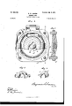
- Figure l is a longitudinal section of a journal-box embodying my invention.
- Fig. 2 is a vertical section on the line 2 2 of Fig. l, looking in the direction of the arrow.
- Fig. 3 is a perspective View of the yoke.
- Fig. l is a similar view of lthe yoke-box. section on line fr of Fig. 2..
- A denotes the journal-box, provided with the removable bonnet c2, which in turn is provided with the' usual hinged door to permit access to the box forinspection or lubricating purposes.
- the bottom of the journal-box is formed with a lubricant-chamber ct', in which a suitable absorbent packing c3 is placed" to retain the lubricant.
- B denotes the axle-journal, the outer end of which is formed with an annular groove b4, and b denotesa dust-guard xed to the inner end of the journal, so as to encompass and close the contiguous open end of the journalbox and prevent the entrance of foreign matter to the bearing.
- journal B denotes a bearing-sleeve which encompasses the journal B, and itis formed at each end with a collar b3.
- F F denote annular grooves formed exter- Fig. 5 is av nyally on the sleeve to receive the' split spring- D represents a yoke, the Vhorizonta-larlns,
- the central portion of the yoke is preferably arch-shaped to receife the yoke-box d', which in turn snugly fits the groove Min the outer end of the journal.
- the inner parallel walls o4 ⁇ d4 of the yoke D engage the corresponding parallel outer Walls of the yoke-box d to prevent the latter rotating in the yoke.
- the upper portion of the yoke-box d is formed with parallel radial flanges dT and d8, which snugly encompass the parallel faces of the yoke, and likewise snugly lit the parallel Walls of the journal-groove b4, the flanges ds preventing any inward longitudinal or end movement ofthe journal and the lflange d? preventing any outward end movement of .theV same, and this latter flange C17 of the box d', in additionA to forming an end bearing in one direction for the journal, also extends across the face of the outer end of the sleeve B', which, ⁇ as shown in Fig.
- the present application is a division of an application for a roller-bearing, Serial No. 693,875, filed by me on the 18th day of October, 1898.
Landscapes
- Engineering & Computer Science (AREA)
- Mechanical Engineering (AREA)
- Mounting Of Bearings Or Others (AREA)
Description
Patented July-1|, (ses. B. s. LAwsoN.
JUUBNAL BOX.
(Applcatiun led Nov. 28, 189B.)
2 Sheets-Sheet I.
(No Model.)
SMQ/Moz m: mms man oo., moi'ournm wmmuton, u. c;
No. 628,480. Patented luly Il, [899.
v B. S. LAWSON.
.IUUBNAL BOX.
cation led Nov. 28, 1898.)
NITED STATES PATENT OFFICE.
BENJAMIN s. LAWSON, OE RED RANK, NEW JERSEY, ASSIGNOR OE THREE- FOURTHS To vAsA L. MERRIoK, EUGENE M. MERRIOK, AND ANDREW J. DE MOTT, OE SYRAOUSE, NEW YORK.
JOURNAL-Box.
SPECIFICATION forming perfor Letters Patent No. 628,480, dated July 11, 1899.
Originalapplioation iiled October 18, 1898, Serial No. 693,875. Divided and this application filed Noveinher28,1898. Serial No. 687,625. V(No model.)
To @ZZ 1072/0117/ t may concern.-
Beit known that I, BENJAMIN S. LAWSON, a
citizen of the United States, residing at Red Bank, in the county of Monmouth and State of New Jersey, 'have-invented certain new and useful Improvements in Journal-Boxes; and I do hereby declare the following to be a full,
. clear, and exact description of the invention, such as will enable others skilled in the art to which it appertains to make and use the saine. My invention relates to improvements in journal-boxes; and the object is to simplify and improve the construction and thereby increase the efficiency and durability of the device.
To these ends the invention consists in the construction, combination, and arrangement of the several elements of the device, as will be hereinafter more fully described, and particularly pointed out in the claims.
In the accompanying drawings the same reference characters indicate the same parts of the invention.
Figure l is a longitudinal section of a journal-box embodying my invention. Fig. 2 is a vertical section on the line 2 2 of Fig. l, looking in the direction of the arrow. Fig. 3 is a perspective View of the yoke. Fig. l is a similar view of lthe yoke-box. section on line fr of Fig. 2..
A denotes the journal-box, provided with the removable bonnet c2, which in turn is provided with the' usual hinged door to permit access to the box forinspection or lubricating purposes. The bottom of the journal-box is formed with a lubricant-chamber ct', in which a suitable absorbent packing c3 is placed" to retain the lubricant.
B denotes the axle-journal, the outer end of which is formed with an annular groove b4, and b denotesa dust-guard xed to the inner end of the journal, so as to encompass and close the contiguous open end of the journalbox and prevent the entrance of foreign matter to the bearing.
B denotes a bearing-sleeve which encompasses the journal B, and itis formed at each end with a collar b3.
F F denote annular grooves formed exter- Fig. 5 is av nyally on the sleeve to receive the' split spring- D represents a yoke, the Vhorizonta-larlns,
of which are arranged to be seated in correspondingly-shaped recesses formed in the inner face of the bonnet, so as to secure the yoke in place when the bonnet is secured on the box and to permit the removal of the yoke when the bonnet is detached. The central portion of the yoke is preferably arch-shaped to receife the yoke-box d', which in turn snugly fits the groove Min the outer end of the journal.
The inner parallel walls o4` d4 of the yoke D engage the corresponding parallel outer Walls of the yoke-box d to prevent the latter rotating in the yoke.
The upper portion of the yoke-box d is formed with parallel radial flanges dT and d8, which snugly encompass the parallel faces of the yoke, and likewise snugly lit the parallel Walls of the journal-groove b4, the flanges ds preventing any inward longitudinal or end movement ofthe journal and the lflange d? preventing any outward end movement of .theV same, and this latter flange C17 of the box d', in additionA to forming an end bearing in one direction for the journal, also extends across the face of the outer end of the sleeve B', which, `as shown in Fig. l, is alined with the inner Wall of the j ournalgroove h4, thus serving the double purpose of preventing any outward end movement of the sleeve or journal, while any movement of the sleeve on the journal in the opposite direction is prevented by the dust-guard b.
In the accompanying drawings I have shown the invention` in the best form now known to me; but various modifications may be employed without departing from the spirit of the invention as set forth in the claims.
The present application is a division of an application for a roller-bearing, Serial No. 693,875, filed by me on the 18th day of October, 1898.
Having thus fully described 'my invention, what I claim as new and useful, and desire to secure by Letters Patent of the United States, 1s-
1. The combination of an axle or shaft formed with an annular groove, a fastening member composed of a main body having the intermediate portion of its lower face provided With shoulders alined with opposite.
sides of the groove in the axle or shaft, and a detachable engaging piece inserted into said groove and formed with shoulders interposed between the former shoulders and the adjacent surfaces of the axle or shaft, and a oasing having a movable bonnet or closure for holding the fastening member in its adjustedposition, said bonnet or Closure being provided With a socket for receiving a portion of the main body of the fastening member, substantially as and for the purpose described,
2. The combination of an axle or shaft formed with an annular groove, a fastening member composed of a mainbody having the intermediate portion of its lower face provide` with shoulders alined with opposite side'of the groove in the axle or shaft, and a detachable engaging piece inserted into said groove and formed with shoulders engaged with opposite sides of the main body, and additional shoulders interposed between the shoulders on the intermediate portion of the lower face of said main body and the adjacent surfaces of the axle vor shaft, and a casing having a movable bonnet or closure for holding the fastening member in its adjusted position, said bonnet or closure being provided With sockets for receiving the ends of the main body of the fastening member, substantially as and for the purpose specified.
3. The combination of an axle or shaft, a sleeve on the axle or shaft, a fastening mem; ber having its intermediate portion engage With the sleeve for preventing endwise move'- ment thereof, and a casing having a movable bonnet or closure for holding the fastening member in position, said bonnet or closure having its inner face provided with sockets for receiving the ends of the fastening mem; ber, substantially as and for the purpose described.
4. The combination of an axle or shaft formed with an annular groove, a sleeve on the axle or shaft at one side of the groove, a casing, and a fastening member supported by the casing and provided with an engaging piece inserted into the groove and having one of its sides engaging with one Wall of the groove and With the sleeve, substantially as and for the purpose described.
In testimony whereof I affix my signature in presence of two Witnesses.
BENJAMIN S. LAWSON.
Vitnesses:
EUGENE M. MERRIGK, H. J. ENNIs.
Priority Applications (1)
| Application Number | Priority Date | Filing Date | Title |
|---|---|---|---|
| US697625A US628480A (en) | 1898-10-18 | 1898-11-28 | Journal-box. |
Applications Claiming Priority (2)
| Application Number | Priority Date | Filing Date | Title |
|---|---|---|---|
| US69387598A US628479A (en) | 1898-10-18 | 1898-10-18 | Bearing. |
| US697625A US628480A (en) | 1898-10-18 | 1898-11-28 | Journal-box. |
Publications (1)
| Publication Number | Publication Date |
|---|---|
| US628480A true US628480A (en) | 1899-07-11 |
Family
ID=2697077
Family Applications (1)
| Application Number | Title | Priority Date | Filing Date |
|---|---|---|---|
| US697625A Expired - Lifetime US628480A (en) | 1898-10-18 | 1898-11-28 | Journal-box. |
Country Status (1)
| Country | Link |
|---|---|
| US (1) | US628480A (en) |
Cited By (1)
| Publication number | Priority date | Publication date | Assignee | Title |
|---|---|---|---|---|
| US2785020A (en) * | 1954-10-08 | 1957-03-12 | Chesapeake & Ohio Railway | Journal bearing |
-
1898
- 1898-11-28 US US697625A patent/US628480A/en not_active Expired - Lifetime
Cited By (1)
| Publication number | Priority date | Publication date | Assignee | Title |
|---|---|---|---|---|
| US2785020A (en) * | 1954-10-08 | 1957-03-12 | Chesapeake & Ohio Railway | Journal bearing |
Similar Documents
| Publication | Publication Date | Title |
|---|---|---|
| US628480A (en) | Journal-box. | |
| US613083A (en) | Journal-bearing | |
| US357737A (en) | Journal-bearing | |
| US722786A (en) | Divided car-axle and journal-box. | |
| US408880A (en) | Car-axle box | |
| US150561A (en) | Improvement in car-axle journals | |
| US438576A (en) | Anti-friction journal-bearing | |
| US1388577A (en) | Hub for rotary colters | |
| US249948A (en) | Leopold kaufman | |
| US312860A (en) | johnstone | |
| US667470A (en) | Journal-box. | |
| US667437A (en) | Dust-guard. | |
| US283421A (en) | Alyik eussell | |
| US183292A (en) | Improvement in car-axle bearings | |
| US727987A (en) | Car-axle box. | |
| US411818A (en) | Anti-friction bearing | |
| US395777A (en) | Car-axle box and bearing | |
| US1245307A (en) | Lateral-motion journal-box | |
| US475835A (en) | Anti-friction bearing | |
| US610147A (en) | Dust-guard for axle-boxes | |
| US607279A (en) | Oil-retaining box | |
| US435124A (en) | Axle-box | |
| US374234A (en) | Axle-box | |
| US1067153A (en) | Journal-box. | |
| US1380456A (en) | Lateral-thrust-bearing appliance for railroad-axles |