US6280132B1 - Fastening arrangement of an assembly part onto a carrier part - Google Patents
Fastening arrangement of an assembly part onto a carrier part Download PDFInfo
- Publication number
- US6280132B1 US6280132B1 US09/258,134 US25813499A US6280132B1 US 6280132 B1 US6280132 B1 US 6280132B1 US 25813499 A US25813499 A US 25813499A US 6280132 B1 US6280132 B1 US 6280132B1
- Authority
- US
- United States
- Prior art keywords
- sleeve
- screw
- head
- flange
- assembly
- Prior art date
- Legal status (The legal status is an assumption and is not a legal conclusion. Google has not performed a legal analysis and makes no representation as to the accuracy of the status listed.)
- Expired - Fee Related
Links
- 230000000717 retained effect Effects 0.000 claims abstract description 7
- 230000006835 compression Effects 0.000 claims abstract description 4
- 238000007906 compression Methods 0.000 claims abstract description 4
- 229920001971 elastomer Polymers 0.000 claims description 11
- 238000003825 pressing Methods 0.000 claims description 9
- 239000004033 plastic Substances 0.000 claims description 5
- 239000002184 metal Substances 0.000 claims description 4
- 239000000806 elastomer Substances 0.000 claims description 2
- 230000004323 axial length Effects 0.000 claims 2
- 238000006073 displacement reaction Methods 0.000 description 3
- 238000004519 manufacturing process Methods 0.000 description 3
- 238000003780 insertion Methods 0.000 description 2
- 230000037431 insertion Effects 0.000 description 2
- 239000007769 metal material Substances 0.000 description 2
- 238000000034 method Methods 0.000 description 2
- 239000000243 solution Substances 0.000 description 2
- 229910000639 Spring steel Inorganic materials 0.000 description 1
- 238000005452 bending Methods 0.000 description 1
- 230000001419 dependent effect Effects 0.000 description 1
- 239000013013 elastic material Substances 0.000 description 1
- 238000005516 engineering process Methods 0.000 description 1
- 238000010438 heat treatment Methods 0.000 description 1
- 238000002347 injection Methods 0.000 description 1
- 239000007924 injection Substances 0.000 description 1
- 238000011068 loading method Methods 0.000 description 1
- 238000003754 machining Methods 0.000 description 1
- 230000014759 maintenance of location Effects 0.000 description 1
- 239000000463 material Substances 0.000 description 1
- 239000011159 matrix material Substances 0.000 description 1
- 230000000284 resting effect Effects 0.000 description 1
- 238000007789 sealing Methods 0.000 description 1
- 238000007493 shaping process Methods 0.000 description 1
- 239000000126 substance Substances 0.000 description 1
- 229920001169 thermoplastic Polymers 0.000 description 1
- 229920002725 thermoplastic elastomer Polymers 0.000 description 1
- 238000007514 turning Methods 0.000 description 1
Images


Classifications
-
- F—MECHANICAL ENGINEERING; LIGHTING; HEATING; WEAPONS; BLASTING
- F02—COMBUSTION ENGINES; HOT-GAS OR COMBUSTION-PRODUCT ENGINE PLANTS
- F02M—SUPPLYING COMBUSTION ENGINES IN GENERAL WITH COMBUSTIBLE MIXTURES OR CONSTITUENTS THEREOF
- F02M35/00—Combustion-air cleaners, air intakes, intake silencers, or induction systems specially adapted for, or arranged on, internal-combustion engines
- F02M35/10—Air intakes; Induction systems
- F02M35/10006—Air intakes; Induction systems characterised by the position of elements of the air intake system in direction of the air intake flow, i.e. between ambient air inlet and supply to the combustion chamber
- F02M35/10078—Connections of intake systems to the engine
-
- F—MECHANICAL ENGINEERING; LIGHTING; HEATING; WEAPONS; BLASTING
- F02—COMBUSTION ENGINES; HOT-GAS OR COMBUSTION-PRODUCT ENGINE PLANTS
- F02F—CYLINDERS, PISTONS OR CASINGS, FOR COMBUSTION ENGINES; ARRANGEMENTS OF SEALINGS IN COMBUSTION ENGINES
- F02F7/00—Casings, e.g. crankcases
- F02F7/006—Camshaft or pushrod housings
-
- F—MECHANICAL ENGINEERING; LIGHTING; HEATING; WEAPONS; BLASTING
- F16—ENGINEERING ELEMENTS AND UNITS; GENERAL MEASURES FOR PRODUCING AND MAINTAINING EFFECTIVE FUNCTIONING OF MACHINES OR INSTALLATIONS; THERMAL INSULATION IN GENERAL
- F16B—DEVICES FOR FASTENING OR SECURING CONSTRUCTIONAL ELEMENTS OR MACHINE PARTS TOGETHER, e.g. NAILS, BOLTS, CIRCLIPS, CLAMPS, CLIPS OR WEDGES; JOINTS OR JOINTING
- F16B41/00—Measures against loss of bolts, nuts, or pins; Measures against unauthorised operation of bolts, nuts or pins
- F16B41/002—Measures against loss of bolts, nuts or pins
-
- F—MECHANICAL ENGINEERING; LIGHTING; HEATING; WEAPONS; BLASTING
- F16—ENGINEERING ELEMENTS AND UNITS; GENERAL MEASURES FOR PRODUCING AND MAINTAINING EFFECTIVE FUNCTIONING OF MACHINES OR INSTALLATIONS; THERMAL INSULATION IN GENERAL
- F16B—DEVICES FOR FASTENING OR SECURING CONSTRUCTIONAL ELEMENTS OR MACHINE PARTS TOGETHER, e.g. NAILS, BOLTS, CIRCLIPS, CLAMPS, CLIPS OR WEDGES; JOINTS OR JOINTING
- F16B5/00—Joining sheets or plates, e.g. panels, to one another or to strips or bars parallel to them
- F16B5/02—Joining sheets or plates, e.g. panels, to one another or to strips or bars parallel to them by means of fastening members using screw-thread
- F16B5/0258—Joining sheets or plates, e.g. panels, to one another or to strips or bars parallel to them by means of fastening members using screw-thread using resiliently deformable sleeves, grommets or inserts
-
- Y—GENERAL TAGGING OF NEW TECHNOLOGICAL DEVELOPMENTS; GENERAL TAGGING OF CROSS-SECTIONAL TECHNOLOGIES SPANNING OVER SEVERAL SECTIONS OF THE IPC; TECHNICAL SUBJECTS COVERED BY FORMER USPC CROSS-REFERENCE ART COLLECTIONS [XRACs] AND DIGESTS
- Y10—TECHNICAL SUBJECTS COVERED BY FORMER USPC
- Y10S—TECHNICAL SUBJECTS COVERED BY FORMER USPC CROSS-REFERENCE ART COLLECTIONS [XRACs] AND DIGESTS
- Y10S411/00—Expanded, threaded, driven, headed, tool-deformed, or locked-threaded fastener
- Y10S411/999—Expanded, threaded, driven, headed, tool-deformed, or locked-threaded fastener with retainer, e.g. tether
Definitions
- the invention relates to a fastening of an assembly part onto a carrier part.
- One possible application of the invention is in automobile technology. e.g., fastening of a cylinder head cover to a cylinder head. Another appreciation is fastening of an intake chamber to a motor.
- a head flange of the sleeve is supported on a rubber ring which is pressed into a receiver of a cylinder head cover.
- a foot flange of the sleeve is buttoned into a through-bore with an undercut of a further rubber part which is arranged between the cylinder head cover and the cylinder head.
- the collar however must have a certain thickness so that on pressing into the through-bore they are not pressed axially together. Because the hooks form the only securement this fastening is not adequately safe in transport. Furthermore the telescoping ability is limited by the abutment of the knurling on the necking so that there prevails a relatively long screwing out of the sleeve and thus the guiding as well as the assembly of the cylinder head cover (assembly part) is made more difficult.
- the rubber ring With another fastening the rubber ring is pressed into the assembly part at its large circumference.
- This sleeve may be arranged in the rubber ring with play so that it may be telescoped up to the abutment of its foot flange on a collar of the rubber ring. Since the screw may also be displaced with respect to the sleeve there results as a whole an enlarged ability to telescope which favours the application on a carrier component.
- the circumferential pressing does not ensure any particularly secure preassembly in the assembly part.
- the foot flange engages behind several undercuts, which in a cover part are preferably injected from plastic.
- the manufacture requires complicated injection tools.
- the undercuts on pressing in the foot flange may shear off so that the transport securement is not ensured.
- a fastening arrangement according to the invention of an assembly part on a carrier part has at least one fastening screw which comprises a screw head with engaging surfaces for a tool, a screw shank, at least one radial projection on the screw shank at a distance from the screw head and a thread at least at the distance of the radial projection from the screw head.
- the radial projection may be formed from the upper end of the thread.
- at least one special projection is present. With this it may be the case of a single projection which extends only about a part or about the whole circumference, or several radial projections which are distributed over the circumference of the screw shank, in particular in the form of a knurling.
- the fastening has a sleeve with an inner diameter which corresponds at least to the outer diameter of the radial projection and of the thread, which preferably at the upper end comprises a narrow location with an inner diameter smaller than the outer diameter of the radial projection, however at least as large as the outer diameter of the screw shank between the screw head and the radial projection.
- the narrow location may be formed by at least one radially inwardly protruding projection of the sleeve.
- the sleeve comprises at the upper end a head flange and at the lower end a foot flange preferably with a smaller diameter than the head flange.
- the fastening screw is applied wherein the narrow location is snapped over the radial projection of the fastening screw and is allocated to the screw head of the outer side of the head flange.
- the applied fastening screw may thus be axially displaced in the sleeve, is however unlosably retained therein by abutment of the radial projection on the narrow location.
- a flexible assembly ring whose inner diameter is smaller than the outer diameter of the foot flange and which is arranged between the head flange and foot flange on the sleeve.
- the assembly ring is elastic so that by broadening, sliding over the flange, preferably the foot flange, and subsequent elastic retraction on the sleeve, it can be assembled on the sleeve.
- a radial play by which means a compensation of tolerances and heat expansions is favoured.
- a through-bore in the assembly part has an inner diameter, which is at least as large as the outer diameter of the foot flange so that the sleeve with the inserted fastening screw may be inserted into the through-bore.
- the inner diameter of the through-bore is dimensioned such that it radially presses together the assembly ring on insertion and by way of this is clamped in and/or the through-bore comprises an undercut with an inner diameter so that the assembly ring under radial compression and subsequent expansion is pushed through the undercut and by which the assembly ring is retained in the through bore.
- the throughbore may have the undercut at the upper end, which may clamp in the assembly ring in an intermediate position and/or after broadening retain it in a bordering bore section. In the bordering bore section the assembly ring may still be clamped in.
- the through bore may however have the same inner diameter everywhere so that it clamps in the assembly ring in every possible insertion location.
- the sleeve is supported with the lower side of the head flange directly over an elastic intermediate position on the upper edge region of the through-bore.
- the carrier part there is present at least one threaded bore into which the thread of the fastening screw is screwed in and on whose edge region there is supported the foot flange of the sleeve.
- the supporting of the assembly part may either be effected directly or via an elastic intermediate layer.
- the fastening according to the invention by way of the radial projection of the fastening screw and the narrow location of the sleeve, the arrangement of the assembly ring between the head flange and the foot flange and the clamping tight and/or the retaining of the assembly ring in the assembly part, favours unlosable pre-assembly.
- a protrusion of the fastening screw out of the assembly part is avoided since the fastening screw with respect to the sleeve as well as the sleeve with respect to the assembly ring may be telescoped.
- the fastening is suitable for the hard screw case as well as for an elastically decoupled screwing. Manufacturing and heat tolerances may be compensated for by play between the sleeve and assembly ring.
- the elements can be easily embodied so that they resist high loadings in particular on account of temperature and aggressive substances, such as for example as occur with motors.
- the invention envisages the fastening of an assembly part to a carrier part with at least one fastening screw, which comprises a screw head with engagement surfaces for a tool and collar, a screw shank, a further collar on the screw shank at a distance from the screw head and a thread at least at the distance of the further collar from the screw head.
- the fastening has a flexible assembly ring whose inner diameter is smaller than the outer diameter of the collars and which is arranged between the collars on the screw shank.
- a through bore in the assembly part whose inner diameter is at least as large as the outer diameter of the further collar, into which the fastening screw is inserted, wherein the lower side of the collar is indirectly or directly supported on the upper edge region of the through-bore, wherein however the inner diameter of the through-bore is dimensioned such that the assembly ring is radially pressed together therein and by way of this is clamped in and/or the through bore comprises an undercut with an inner diameter so that the assembly ring under radial compression and subsequent expansion is pushed through the undercut and by which the assembly ring is retained in the through-bore.
- the fastening has a threaded bore in the carrier part into which is screwed the thread of the fastening screw and on whose edge region the further collar is supported.
- the collar and the further collar of the fastening screw assume essentially the function of the head flange and foot flange of the sleeve, which is done away with.
- Particularities of the head flange and the foot flange from the dependent claims may in as far as is possible, be transmitted to the collar and the further collar of the fastening screw.
- FIG. 1 is an assembly ring in plan view (a) and in longitudinal section (b);
- FIG. 2 is an assembly ring with end sections for supporting a sleeve in an intermediate position in plan view (a) and in longitudinal section (b);
- FIG. 3 is an assembly ring with end regions of increased flexibility in plan view (a) and in an intermediate position in longitudinal section (b);
- FIG. 4 is an assembly ring with inner projecting contact regions on the two ends in plan view (a) and in an intermediate position in longitudinal section (b);
- FIG. 5 is a metallic assembly ring in the plan view (a) and in longitudinal section (b);
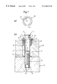
- FIG. 6 is an assembly ring in the plan view (a) and a fastening with the assembly ring and a collar screw in longitudinal section (b).
- the fastening arrangement according to FIG. 1 includes a fastening screw 10 , a sleeve 20 , an assembly ring 30 , an assembly part 40 and a carrier part 50 .
- the fastening screw 10 has a head 11 formed at a lower side thereof with a radially projecting collar 12 and a screw shank 13 which comprises a knurling 14 located a distance from the screw head and which extends over the whole circumference.
- the screw shank 13 Up to the knurling 14 the screw shank 13 is formed smoothly cylindrical.
- the outer diameter of the knurling 14 which is taken on a circle laid by the outer ends of the knurling is larger than the smooth cylindrical region of the screw shank 13 .
- the screw shank 13 On the side of the knurling 14 distant to the screw head 11 the screw shank 13 carries a thread 15 whose outer diameter is somewhat smaller than the outer diameter of the knurling 14 .
- the fastening screw 10 At the lower end the fastening screw 10 has a cylindrical introduction peg 16 , whose outer diameter again is smaller than that of the thread 15 .
- the screw 10 is preferably manufactured from a metallic material wherein the knurling 14 and the thread 15 may be rolled.
- the sleeve 20 has a smooth cylindrical section 21 , whose inner diameter somewhat exceeds the outer diameter of the knurling 14 so that displacement of the fastening screw 10 in the sleeve 20 is possible.
- the sleeve 20 on the inside has a narrow location in the form of a circumferential necking 22 .
- the necking 22 is recognizable as a slightly bulged contour on the inner side of the sleeve 20 .
- Its inner diameter i.e. the diameter at the location of its smallest cross section, is smaller than the outer diameter of the knurling 14 , but somewhat larger than the outer diameter of the smooth-cylindrical region of the screw shank 13 .
- the screw 10 is also somewhat larger than the outer diameter of the thread 15 so that this is not damaged on passage.
- the necking 22 and the knurling 14 there is practically no play present between the sleeve 20 and the fastening screw 10 so that the screw 10 can be tilted with respect to the sleeve 20 only negligibly.
- the sleeve has a radially outwardly projecting head flange 23 and at the lower end it comprises a radially outwardly projecting foot flange 24 .
- the outer diameter of the head flange 23 is larger than the outer diameter of the foot flange 24 .
- the sleeve 20 is preferably likewise manufactured of a metallic material, wherein the necking 22 as well as the head flange 24 may be manufactured by a shaping procedure. The latter at the same time may be manufactured by two beading procedures in opposite directions, by which means there results a doubling of the wall thickness.
- the sleeve 20 may however also be manufactured by swarf-producing machining, e. g. by turning.
- the assembly ring 30 is formed smooth-cylindrically with bevelings 31 , 32 at the upper and lower end. On its side it comprises a longitudinal slot 33 whose width slightly reduces towards its centre. The longitudinal slot with respect to its plane of cross section through its centre 34 is formed symmetrically. Its inner diameter somewhat exceeds the outer diameter of the middle section 21 of the sleeve 20 , but is somewhat smaller than the outer diameter of the foot flange 24 .
- the assembly ring 30 is elastic. For application with motors it may be designed resistant to oil and heating. It may be manufactured of an elastic material for example of a thermoplastic plastic, of an elastomer or thermoplastic elastomer. It may also consist of metal.
- the assembly part 40 has a through-bore 41 , whose inner diameter is somewhat larger than the outer diameter of the foot flange 24 , but smaller than the outer diameter of the assembly ring 30 in the untensioned condition.
- the through-bore 41 ha s an undercut 42 with an even smaller inner diameter. This is however so large that the foot flange 24 may be guided through, on the other hand, the head flange 23 does not fit through, but considerably overlaps the upper edge region of the through-bore 41 .
- the inner diameter of the undercut 42 and the outer diameter of the assembly ring 30 are dimensioned such that the assembly ring on passing through is maximally pressed together so far radially that it bears on the outer side of the sleeve 20 or the two ends of the assembly ring 30 abut against one another.
- the assembly part 40 may consist of metal or of plastic.
- the assembly part 40 and the carrier part 50 abut against one another with planar sides.
- the carrier part 50 has a threaded bore 51 receiving the thread of the fastening screw 10 .
- the foot flange 24 may be supported on the upper edge region of the threaded bore 51 .
- the length of the sleeve 20 and the through-bore 41 are matched to one another such that with a resting foot flange 24 the head flange 23 rests on the upper edge region of the through-bore 41 and the assembly part 40 is pressed between the head flange 23 and the carrier part 50 in a controlled manner.
- This fastening is pre-mounted in that the fastening screw 10 is first pressed into the upper end of the sleeve 20 until the necking 22 snaps behind the knurling 14 .
- the assembly ring 30 is widened until is fits over the foot flange 24 and is then pushed over the section 21 and springs back together elastically. Due to its symetry, ring 30 need not be oriented in a certain manner for mounting.
- This unit may then be pre-mounted with the assembly part 40 in that the sleeve 20 is inserted into the through-bore 41 and the assembly ring 30 seated thereon is pressed in. If the assembly ring 30 has passed the undercut 42 it is untensioned somewhat.
- the undercut 42 and the remaining clamping then prevent the assembly ring 30 from exiting upwards out of the through-bore.
- the head flange 23 prevents the sleeve 20 from falling downwards out of the through bore 41 .
- the pre-assembly is thus securely protected from an unintentional falling apart even when the assembly part 40 with the screw head 11 is transported downwards.
- the fastening screw 10 may slide up to the abutment of the knurling 14 on the necking 22 and the sleeve 20 up to the abutment of the foot flange 24 on the assembly ring.
- the lower end 16 of the fastening screw 10 may recede in the through-bore 41 . This is particularly advantageous when the threaded bores 51 by displacement of the assembly part 40 must be “searched” on the carrier part 50 until the fastening screws with the introduction pegs 16 fall into the threaded bores 51 , in particular when the assembly part 40 at several locations must be fixed in this manner.
- the fastening screw 10 is screwed into the carrier part 50 until its collar 12 exerts a sufficient clamping force onto the head flange 23 in order to tension the sleeve 20 with the carrier part 50 and the assembly part 40 , between the head flange 23 and carrier part 50 .
- the play between the sleeve 20 and the assembly ring 30 ensures the compensation of manufacturing tolerances and heat expansions.
- FIG. 2 relates to a solution of this problem.
- the assembly ring 30 above and below in each case has a smooth-cylindrical end section 34 , 35 with a reduced diameter, wherein however the inner diameter of the assembly ring 30 is constant everywhere.
- the assembly ring 30 is exactly snapped with its beveling 31 behind the undercut 42 of the through-bore 41 of the assembly part 40 .
- the assembly ring is still pressed together somewhat so that it is retained in this position by a remaining clamping.
- the upper end section 34 above protrudes somewhat beyond the assembly part 40 .
- the head flange 23 of the sleeve 20 is supported on the upper end section 34 .
- the fastening screw 10 may be slid somewhat higher than if the head flange 23 is seated on the upper side of the assembly part 40 .
- the introduction peg 16 of the fastening screw 10 may be completely pushed into the through-bore without the head flange 23 being lifted from its support on the upper end section 34 of the assembly sleeve 30 .
- the sleeve 20 does not tilt and the screw head 11 is retained in a position which may be securely controlled also by an automatic screwing tool.
- the assembly ring 30 is completely pressed into the assembly part.
- the assembly ring 30 above and below in each case has an axial circumferential slot 36 , 37 .
- the assembly ring 30 on the outside at half the height has a circumferential annular groove 38 .
- the annular groove 38 may just accommodate the undercut 42 in order to secure the assembly ring 30 in an intermediate position.
- the inner diameter of the assembly ring 30 is selected such that the sleeve 20 may be guided therein in a manner free of play and with a horizontal alignment that does not tilt. As a result of this also in a horizontal screwing case the locating of the screw head 11 with a screwing tool is simplified.
- the assembly ring 30 is completely pressed into the through-bore 41 on screwing in the fastening screw 10 .
- FIG. 4 shows an embodiment which is suitable for a horizontal screwing case in which the pressing in of the assembly ring 30 is favoured by way of an increased flexibility.
- the assembly ring 30 at the upper and lower end in each case has inwardly projecting contact regions 39 , 39 ′.
- the inner diameter of the contact regions corresponds roughly to the outer diameter of the section 21 of the sleeve 20 so that a displacement of the two parts relative to one another is possible without tilting.
- the inner diameter of the assembly part between the contact surfaces 39 , 39 ′ is larger than the outer diameter of the section 21 .
- the lower slant 32 favours the leading through of the lower contact region 39 ′ through the undercut 42 of the assembly part 40 .
- the assembly ring 30 deflects radially inwards between the contact regions 39 , 39 ′ until its annular groove 38 accommodates the undercut 42 .
- the sleeve 20 is in turn supported so high that the fastening screw 10 with its introduction peg 16 with or without lifting the sleeve 20 can be engaged into the through-bore 41 .
- a pivoting of the sleeve 20 with respect to the assembly ring 30 is prevented by the contact regions 39 , 39 ′ and by way of this the screwing is favoured.
- the assembly ring 30 again is completely pressed into the through-bore 41 , until the slant 31 is arranged behind the undercut 42 .
- FIG. 5 shows an embodiment form with an assembly ring 30 preferably of spring steel.
- the assembly ring 30 is formed barrel-shaped and likewise comprises a slot 33 . It is manufactured in that a tape material is drawn through a matrix and subsequently rolled to a ring.
- This assembly ring 30 acts similarly to that in FIG. 4, since its concave inner contour at the upper and lower end forms supports 39 , 39 ′.
- Such an assembly ring 30 may also consist of plastic.
- FIG. 6 shows an embodiment with a “collar screw” 10 ′, which apart from the collar 12 at the lower side of the head 11 at the end of a smooth-cylindrical screw shank 13 comprises a further collar 17 from which in turn the thread 15 extends.
- the fastening screw 10 ′ is fixed with the help of an elastic assembly ring 30 into a through-guide 41 of an assembly part 40 .
- the inner diameter of the through-bore 41 is somewhat larger than the outer diameter of the further collar 17 , but smaller than the outer diameter of the assembly ring 30 in the untensioned condition.
- the through-bore 41 above has an undercut 42 with an even smaller inner diameter, which is however so large that the further collar 17 may be guided through, but on the other hand the collar 12 cannot pass through, but considerably overlaps the upper edge region of the through-bore 41 .
- the assembly ring 30 is maximumly pressed radially so far together that it bears on the outer side of the screw shank 13 or its two ends abut against one another. If the assembly ring 30 has passed the undercut 42 it untensions somewhat and is rigidly seated in the through-bore 41 below the undercut 42 in a secured position.
- the further collar 17 is supported on the non-shown carrier part and the assembly part 40 is clamped rigidly between the collar 12 and the carrier part.
Landscapes
- Engineering & Computer Science (AREA)
- General Engineering & Computer Science (AREA)
- Mechanical Engineering (AREA)
- Chemical & Material Sciences (AREA)
- Combustion & Propulsion (AREA)
- Bolts, Nuts, And Washers (AREA)
- Connection Of Plates (AREA)
- Surgical Instruments (AREA)
- Screw Conveyors (AREA)
- Mounting Of Bearings Or Others (AREA)
- Motor Or Generator Frames (AREA)
- Magnetic Bearings And Hydrostatic Bearings (AREA)
- Clamps And Clips (AREA)
- Supports Or Holders For Household Use (AREA)
Abstract
Description
Claims (20)
Applications Claiming Priority (2)
| Application Number | Priority Date | Filing Date | Title |
|---|---|---|---|
| DE29804041U | 1998-03-07 | ||
| DE29804041U DE29804041U1 (en) | 1998-03-07 | 1998-03-07 | Attachment of an assembly part to a support part |
Publications (1)
| Publication Number | Publication Date |
|---|---|
| US6280132B1 true US6280132B1 (en) | 2001-08-28 |
Family
ID=8053747
Family Applications (1)
| Application Number | Title | Priority Date | Filing Date |
|---|---|---|---|
| US09/258,134 Expired - Fee Related US6280132B1 (en) | 1998-03-07 | 1999-02-26 | Fastening arrangement of an assembly part onto a carrier part |
Country Status (6)
| Country | Link |
|---|---|
| US (1) | US6280132B1 (en) |
| EP (1) | EP0942164B1 (en) |
| AT (1) | ATE278871T1 (en) |
| BR (1) | BR9900884A (en) |
| CA (1) | CA2263025C (en) |
| DE (2) | DE29804041U1 (en) |
Cited By (60)
| Publication number | Priority date | Publication date | Assignee | Title |
|---|---|---|---|---|
| US6485241B1 (en) * | 1996-01-03 | 2002-11-26 | J. Craig Oxford | Surface mount ring assembly for loudspeaker |
| US20030180122A1 (en) * | 2001-02-07 | 2003-09-25 | Dobson Kenneth S. | Body bolt absorber assembly |
| US6626626B2 (en) * | 2000-11-09 | 2003-09-30 | Kamax-Werke Rudolf Kellermann Gmbh & Co. Kg | Assembly unit including a component and at least one screw |
| US20040022600A1 (en) * | 2002-08-01 | 2004-02-05 | Newfrey Llc | Device for holding a piece in a bore |
| US20040109742A1 (en) * | 2002-08-01 | 2004-06-10 | Newfrey Llc | Device, assembly, and method for holding a piece in a bore |
| US20050057075A1 (en) * | 2003-09-16 | 2005-03-17 | Edwards David Michael | Fastening system with bearing member |
| US6883859B2 (en) | 2003-09-16 | 2005-04-26 | Honda Motor Company, Ltd. | Fastening system with extension element |
| US20050193546A1 (en) * | 2004-03-02 | 2005-09-08 | Paul Gaudron | Fastener assembly, barrier, and method for assembling of a fastener assembly |
| US20050244219A1 (en) * | 2002-08-29 | 2005-11-03 | Rainer Mathes | Device for fixing a vacuum pump |
| US20060063598A1 (en) * | 2004-09-21 | 2006-03-23 | Hitachi, Ltd. | Support structure for bolting components of drive shaft via mounting member |
| US7073997B2 (en) | 2002-10-02 | 2006-07-11 | Newfrey Llc | Apparatus and method for holding a piece in a bore |
| US20060171794A1 (en) * | 2005-01-25 | 2006-08-03 | Ordonio Anthony Jr | Seal nut assembly and method of manufacture |
| US20070065251A1 (en) * | 2005-09-20 | 2007-03-22 | Airbus Deutschland Gmbh | Lockbolt and production method for joining at least two component layers |
| US20070125004A1 (en) * | 2005-12-07 | 2007-06-07 | Robert Conner | Upper reveal molding snap-in 4-way locator insert |
| USD548580S1 (en) * | 2005-08-25 | 2007-08-14 | Grinaker-Lta Limited | Bolt |
| US20080075403A1 (en) * | 2006-09-27 | 2008-03-27 | Jason Holt | Work Piece Isolating Assembly |
| US20080095593A1 (en) * | 2006-10-18 | 2008-04-24 | Mclean Shawn G | Compression Limiter |
| US20080105498A1 (en) * | 2006-06-12 | 2008-05-08 | Genie Industries, Inc. | Joint assembly and related methods |
| US20090110478A1 (en) * | 2007-10-26 | 2009-04-30 | Richard Bergner Verbindungstechnik Gmbh & Co Kg | Assembly unit |
| US20090123252A1 (en) * | 2007-11-14 | 2009-05-14 | Newfrey Llc | Power Seal Bolt Assembly |
| US20100202856A1 (en) * | 2009-02-12 | 2010-08-12 | Acument Intellectual Properties, Llc | Isolator assembly and method of installation |
| DE102010001027A1 (en) | 2009-01-22 | 2010-12-30 | Richard Bergner Verbindungstechnik Gmbh & Co. Kg | assembly unit |
| US20110034281A1 (en) * | 2005-03-28 | 2011-02-10 | York Industries Inc. | Device for placing looped belt under tension |
| CN102251871A (en) * | 2010-05-17 | 2011-11-23 | 通用汽车环球科技运作有限责任公司 | Cylinder head dry valley drain |
| US20110286813A1 (en) * | 2008-11-26 | 2011-11-24 | Illinois Tool Works Inc. | Fastening means for pre-assembly of a pin-shaped joining means in a through-hole of a structural element |
| US20110311333A1 (en) * | 2009-03-04 | 2011-12-22 | Illinois Tool Works Inc. | Bushing assembly |
| US20120093609A1 (en) * | 2010-10-13 | 2012-04-19 | Christian Richard Trifilio | Screw Captivator |
| CN103104581A (en) * | 2011-11-11 | 2013-05-15 | 沃尔沃汽车公司 | Screw assembly element |
| US20130206911A1 (en) * | 2012-02-10 | 2013-08-15 | Bell Helicopter Textron Inc. | Attachment Devices for Rotorcraft Front Windshield |
| US20130244805A1 (en) * | 2007-04-13 | 2013-09-19 | Cobra Golf Incorporated | Interchangeable shaft and club head connection system |
| US20130336741A1 (en) * | 2012-06-18 | 2013-12-19 | Dongyang Mechatronics Corp. | Bolt Assembly for Wiper Device of Vehicle |
| US20130340714A1 (en) * | 2011-03-04 | 2013-12-26 | Giandomenico Serra | Coupling Device |
| CN103649567A (en) * | 2011-07-12 | 2014-03-19 | 伊利诺斯工具制品有限公司 | Fastener retainer |
| US20150023756A1 (en) * | 2008-01-08 | 2015-01-22 | Cloyes Gear And Products, Inc. | Captive fastener apparatus for chain guide or tensioner arm |
| CN104500543A (en) * | 2014-11-25 | 2015-04-08 | 广西大学 | Anti-falling structure of screw mounting sleeve |
| US20150267609A1 (en) * | 2014-03-19 | 2015-09-24 | Ford Global Technologies, Llc | Engine cover integrated captive fastener |
| US9174097B1 (en) * | 2011-03-10 | 2015-11-03 | Callaway Golf Company | Adjustable golf club shaft and hosel assembly |
| US20150369269A1 (en) * | 2013-01-02 | 2015-12-24 | Illinois Tool Works Inc. | Twist-in-place grommet connection assembly |
| US20160207569A1 (en) * | 2013-08-30 | 2016-07-21 | Toyota Jidosha Kabushiki Kaisha | Fastening portion structure of vehicle |
| US20180094667A1 (en) * | 2016-10-04 | 2018-04-05 | Illinois Tool Works Inc. | Fastener assembly having one or more grommets |
| US20180142714A1 (en) * | 2015-06-19 | 2018-05-24 | Illinois Tool Works Inc. | Fastener-retaining system and method |
| US10228012B2 (en) | 2006-12-05 | 2019-03-12 | Illinois Tool Works Inc. | Bushing assembly |
| US20190383315A1 (en) * | 2018-06-18 | 2019-12-19 | General Fasteners Company | Compression limiter fastener assembly |
| US10550876B2 (en) | 2011-12-05 | 2020-02-04 | Acument Intellectual Properties, Llc | Fastener with attached compression limiting sleeve |
| DE102018127682A1 (en) * | 2018-11-02 | 2020-05-07 | Carl Mahr Holding Gmbh | Arrangement with an adjustment device for adjusting the position of two interconnected components |
| CN111425511A (en) * | 2019-01-09 | 2020-07-17 | 伊利诺斯工具制品有限公司 | Device for captive fastener assembly with expansion grommet |
| CN111976826A (en) * | 2019-05-21 | 2020-11-24 | 罗伯特·博世有限公司 | Housing part assembly, in particular for a drive unit in a motor vehicle |
| USD918700S1 (en) * | 2020-02-03 | 2021-05-11 | Wheel Pros, Llc | Bolt |
| USD918701S1 (en) * | 2020-02-03 | 2021-05-11 | Wheel Pros, Llc | Bolt |
| US11149768B2 (en) * | 2016-11-09 | 2021-10-19 | Illinois Tool Works Inc. | Fastener assembly having a component-isolating grommet |
| CN113752221A (en) * | 2020-06-03 | 2021-12-07 | 施耐宝公司 | Insert for a power tool housing |
| US20220002990A1 (en) * | 2020-07-01 | 2022-01-06 | Siemens Gamesa Renewable Energy A/S | Stud system for connecting flanges |
| US20220074445A1 (en) * | 2020-09-08 | 2022-03-10 | Apq Development, Llc | Fastener Retainer |
| US20220120285A1 (en) * | 2020-10-16 | 2022-04-21 | Ebm-Papst Mulfingen Gmbh & Co. Kg | Fan with a rotor and a fan impeller |
| USD952450S1 (en) * | 2020-02-03 | 2022-05-24 | Wheel Pros, Llc | Bolt |
| US11371544B2 (en) | 2011-12-05 | 2022-06-28 | Acument Intellectual Properties, Llc | Fastener with attached compression limiting sleeve |
| US20220307543A1 (en) * | 2017-04-05 | 2022-09-29 | Honsel Umformtechnik Gmbh | Securing means and system for pre-mounting a pencil-shaped connecting element |
| US11549547B2 (en) * | 2017-01-06 | 2023-01-10 | Sibas Electronics (Xiamen) Co., Ltd. | Locking device and connector |
| US11732744B2 (en) * | 2019-02-13 | 2023-08-22 | The Boeing Company | Straight shank end screw for foreign-object-debris (FOD) reduction |
| US12025175B2 (en) | 2018-11-02 | 2024-07-02 | Carl Mahr Holding Gmbh | Arrangement with an adjustment device for position adjustment of two parts connected with each other |
Families Citing this family (13)
| Publication number | Priority date | Publication date | Assignee | Title |
|---|---|---|---|---|
| EP1170515A3 (en) * | 2000-07-05 | 2002-10-30 | Siemens Canada Limited | Cylindrical compression limiter, intake manifold with such a limiter and method of forming such a compression limiter |
| US6804872B2 (en) | 2000-07-05 | 2004-10-19 | Siemens Vdo Automotive Inc. | Method of forming a roll pin compression limiter |
| DE10104672B4 (en) * | 2001-02-02 | 2004-04-15 | Kamax-Werke Rudolf Kellermann Gmbh & Co. Kg | Assembly unit consisting of one component and at least one screw |
| DE10113044C2 (en) * | 2001-03-15 | 2003-07-03 | Itw Automotive Prod Gmbh & Co | System for fastening a component to a carrier component |
| DE10225260A1 (en) * | 2001-09-07 | 2003-03-27 | Alstom Switzerland Ltd | Flange connection for turbine blade mounting comprises bolt mounted in sleeve in bore through both halves of mounting, thermal insulation being fitted between sleeve and inner wall of bore |
| DE10202267A1 (en) * | 2002-01-22 | 2003-07-31 | Ejot Gmbh & Co Kg | support sleeve |
| DE102007026568A1 (en) * | 2007-06-08 | 2008-12-11 | Ejot Gmbh & Co. Kg | support sleeve |
| DE102009014847A1 (en) * | 2009-03-30 | 2010-10-14 | Autoliv Development Ab | Fastening device for securely fastening safety seat belt of belt retractor at vehicle structure, has cylindrical section whose inner diameter is dimensioned such that retainer is fastened to section by friction conclusive connection |
| DE102009023790A1 (en) * | 2009-06-03 | 2010-12-09 | Elringklinger Ag | Screw for securing a first component to a second component |
| DE102010039266A1 (en) | 2010-08-12 | 2012-03-29 | Zf Friedrichshafen Ag | Arrangement for fastening of secondary element e.g. lid, at primary element i.e. housing, of gear box of motor car, has attachment screw running through receiving part, where outer contour of attachment screw is adapted to diameter of hole |
| DE202011102725U1 (en) * | 2011-07-01 | 2012-10-25 | Mahle International Gmbh | Guide and Fixierbuchse |
| FR3064035B1 (en) * | 2017-03-16 | 2019-04-19 | Sogefi Air & Cooling | REMOVABLE SLEEVE FOR HOLDING AND ATTACHING SCREWS |
| EP4386202A1 (en) * | 2022-12-16 | 2024-06-19 | Siemens Gamesa Renewable Energy A/S | Retaining mechanism for a tower segment of a wind turbine tower, and mounting method |
Citations (8)
| Publication number | Priority date | Publication date | Assignee | Title |
|---|---|---|---|---|
| US1409606A (en) * | 1921-05-25 | 1922-03-14 | Bryant Electric Co | Screw retainer |
| US3811733A (en) * | 1972-06-26 | 1974-05-21 | Dayton Steel Foundry Co | Retained fastening elements for a rim and wheel assembly |
| US4732519A (en) * | 1986-12-24 | 1988-03-22 | Illinois Tool Works Inc. | Fastener assembly with axial play |
| US5094579A (en) * | 1990-10-19 | 1992-03-10 | Johnson H Thad | Fastener and grommet assembly providing axial play |
| US5244325A (en) * | 1992-09-28 | 1993-09-14 | Elco Industries, Inc. | Fastener assembly with axially slidable sleeve |
| US5255647A (en) * | 1993-02-08 | 1993-10-26 | Freudenberg-Nok General Partnership | Elastomeric grommet-fastener assembly |
| US5662444A (en) * | 1994-06-08 | 1997-09-02 | Crest Products, Inc. | Fastener assembly with axially captivated washer |
| US5871319A (en) * | 1995-12-23 | 1999-02-16 | Richard Bergner Gmbh & Co. | Assembly arrangement including cuff with radially inwardly protruding fastening region |
Family Cites Families (5)
| Publication number | Priority date | Publication date | Assignee | Title |
|---|---|---|---|---|
| US3156281A (en) * | 1960-11-04 | 1964-11-10 | Robertshaw Controls Co | Fastener assembly with resilient locking retainer |
| US5154559A (en) * | 1991-07-25 | 1992-10-13 | Illinois Tool Works Inc. | Captivating a fastener to a workpiece |
| DE4310002C1 (en) * | 1993-03-27 | 1994-04-21 | Kellermann Fa Rudolf | Noise discharge connecting component - has body with projection having recess in which seal sits and has friction surfaces between body and screw |
| US5489177A (en) * | 1994-06-08 | 1996-02-06 | Crest Products, Inc. | Fastener assembly with axially captivated washer |
| US5807052A (en) * | 1997-06-27 | 1998-09-15 | Illinois Tool Works Inc. | Pre-assembled manifold fastener system and method therefor |
-
1998
- 1998-03-07 DE DE29804041U patent/DE29804041U1/en not_active Expired - Lifetime
-
1999
- 1999-02-11 AT AT99102565T patent/ATE278871T1/en not_active IP Right Cessation
- 1999-02-11 DE DE69920788T patent/DE69920788T2/en not_active Expired - Lifetime
- 1999-02-11 EP EP99102565A patent/EP0942164B1/en not_active Expired - Lifetime
- 1999-02-25 CA CA002263025A patent/CA2263025C/en not_active Expired - Fee Related
- 1999-02-26 US US09/258,134 patent/US6280132B1/en not_active Expired - Fee Related
- 1999-03-04 BR BR9900884-0A patent/BR9900884A/en not_active IP Right Cessation
Patent Citations (8)
| Publication number | Priority date | Publication date | Assignee | Title |
|---|---|---|---|---|
| US1409606A (en) * | 1921-05-25 | 1922-03-14 | Bryant Electric Co | Screw retainer |
| US3811733A (en) * | 1972-06-26 | 1974-05-21 | Dayton Steel Foundry Co | Retained fastening elements for a rim and wheel assembly |
| US4732519A (en) * | 1986-12-24 | 1988-03-22 | Illinois Tool Works Inc. | Fastener assembly with axial play |
| US5094579A (en) * | 1990-10-19 | 1992-03-10 | Johnson H Thad | Fastener and grommet assembly providing axial play |
| US5244325A (en) * | 1992-09-28 | 1993-09-14 | Elco Industries, Inc. | Fastener assembly with axially slidable sleeve |
| US5255647A (en) * | 1993-02-08 | 1993-10-26 | Freudenberg-Nok General Partnership | Elastomeric grommet-fastener assembly |
| US5662444A (en) * | 1994-06-08 | 1997-09-02 | Crest Products, Inc. | Fastener assembly with axially captivated washer |
| US5871319A (en) * | 1995-12-23 | 1999-02-16 | Richard Bergner Gmbh & Co. | Assembly arrangement including cuff with radially inwardly protruding fastening region |
Cited By (105)
| Publication number | Priority date | Publication date | Assignee | Title |
|---|---|---|---|---|
| US6485241B1 (en) * | 1996-01-03 | 2002-11-26 | J. Craig Oxford | Surface mount ring assembly for loudspeaker |
| US6626626B2 (en) * | 2000-11-09 | 2003-09-30 | Kamax-Werke Rudolf Kellermann Gmbh & Co. Kg | Assembly unit including a component and at least one screw |
| US7131809B2 (en) * | 2001-02-07 | 2006-11-07 | Illinois Tool Works Inc | Body bolt absorber assembly |
| US20030180122A1 (en) * | 2001-02-07 | 2003-09-25 | Dobson Kenneth S. | Body bolt absorber assembly |
| US20040022600A1 (en) * | 2002-08-01 | 2004-02-05 | Newfrey Llc | Device for holding a piece in a bore |
| US20040109742A1 (en) * | 2002-08-01 | 2004-06-10 | Newfrey Llc | Device, assembly, and method for holding a piece in a bore |
| US7029219B2 (en) * | 2002-08-01 | 2006-04-18 | Newfrey Llc | Device, assembly, and method for holding a piece in a bore |
| US7029221B2 (en) * | 2002-08-01 | 2006-04-18 | Newfrey Llc | Sleeve device with internal fins for holding a piece such as a bolt in a bore |
| US20050244219A1 (en) * | 2002-08-29 | 2005-11-03 | Rainer Mathes | Device for fixing a vacuum pump |
| US8016512B2 (en) * | 2002-08-29 | 2011-09-13 | Alcatel | Device for fixing a vacuum pump |
| US7073997B2 (en) | 2002-10-02 | 2006-07-11 | Newfrey Llc | Apparatus and method for holding a piece in a bore |
| US20060216136A1 (en) * | 2002-10-02 | 2006-09-28 | Newfrey Llc | Apparatus and method for holding a piece in a bore |
| US8020278B2 (en) | 2002-10-02 | 2011-09-20 | Newfrey Llc | Method for holding a piece in a bore |
| US7086688B2 (en) | 2003-09-16 | 2006-08-08 | Honda Motor Company, Ltd. | Fastening system with bearing member |
| US6883859B2 (en) | 2003-09-16 | 2005-04-26 | Honda Motor Company, Ltd. | Fastening system with extension element |
| US20050057075A1 (en) * | 2003-09-16 | 2005-03-17 | Edwards David Michael | Fastening system with bearing member |
| US20050196250A1 (en) * | 2004-03-02 | 2005-09-08 | Paul Gaudron | Fastener assembly, barrier, and method for assembling of a fastener assembly |
| US20050193546A1 (en) * | 2004-03-02 | 2005-09-08 | Paul Gaudron | Fastener assembly, barrier, and method for assembling of a fastener assembly |
| US20060063598A1 (en) * | 2004-09-21 | 2006-03-23 | Hitachi, Ltd. | Support structure for bolting components of drive shaft via mounting member |
| US8353779B2 (en) * | 2004-09-21 | 2013-01-15 | Hitachi, Ltd. | Support structure for bolting components of drive shaft via mounting member |
| US20060171794A1 (en) * | 2005-01-25 | 2006-08-03 | Ordonio Anthony Jr | Seal nut assembly and method of manufacture |
| US7581913B2 (en) | 2005-01-25 | 2009-09-01 | Honda Motor Company, Ltd. | Seal nut assembly and method of manufacture |
| US8287410B2 (en) * | 2005-03-28 | 2012-10-16 | York Industries, Inc. | Device for placing looped belt under tension |
| US20110034281A1 (en) * | 2005-03-28 | 2011-02-10 | York Industries Inc. | Device for placing looped belt under tension |
| USD548580S1 (en) * | 2005-08-25 | 2007-08-14 | Grinaker-Lta Limited | Bolt |
| US20070065251A1 (en) * | 2005-09-20 | 2007-03-22 | Airbus Deutschland Gmbh | Lockbolt and production method for joining at least two component layers |
| US20070125004A1 (en) * | 2005-12-07 | 2007-06-07 | Robert Conner | Upper reveal molding snap-in 4-way locator insert |
| WO2007146962A3 (en) * | 2006-06-12 | 2008-11-06 | Genie Ind Inc | Joint assembly and related methods |
| US20080105498A1 (en) * | 2006-06-12 | 2008-05-08 | Genie Industries, Inc. | Joint assembly and related methods |
| US7682117B2 (en) * | 2006-09-27 | 2010-03-23 | Illinois Tool Works Inc. | Work piece isolating assembly |
| US20080075403A1 (en) * | 2006-09-27 | 2008-03-27 | Jason Holt | Work Piece Isolating Assembly |
| US7708512B2 (en) * | 2006-10-18 | 2010-05-04 | Newfrey Llc | Compression limiter |
| US20080095593A1 (en) * | 2006-10-18 | 2008-04-24 | Mclean Shawn G | Compression Limiter |
| US10228012B2 (en) | 2006-12-05 | 2019-03-12 | Illinois Tool Works Inc. | Bushing assembly |
| US9114291B2 (en) * | 2007-04-13 | 2015-08-25 | Cobra Golf Incorporated | Interchangeable shaft and club head connection system |
| US20150314173A1 (en) * | 2007-04-13 | 2015-11-05 | Cobra Golf Incorporated | Interchangeable shaft and club head connection system |
| US20130244805A1 (en) * | 2007-04-13 | 2013-09-19 | Cobra Golf Incorporated | Interchangeable shaft and club head connection system |
| US8057122B2 (en) * | 2007-10-26 | 2011-11-15 | Richard Bergner Verbindungstechnik Gmbh & Co. Kg | Assembly unit |
| US20090110478A1 (en) * | 2007-10-26 | 2009-04-30 | Richard Bergner Verbindungstechnik Gmbh & Co Kg | Assembly unit |
| US7753633B2 (en) | 2007-11-14 | 2010-07-13 | Newfrey Llc | Power seal bolt assembly |
| US20090123252A1 (en) * | 2007-11-14 | 2009-05-14 | Newfrey Llc | Power Seal Bolt Assembly |
| US20150023756A1 (en) * | 2008-01-08 | 2015-01-22 | Cloyes Gear And Products, Inc. | Captive fastener apparatus for chain guide or tensioner arm |
| US9297406B2 (en) * | 2008-01-08 | 2016-03-29 | Cloyes Gear And Products, Inc. | Captive fastener apparatus for chain guide or tensioner arm |
| US20110286813A1 (en) * | 2008-11-26 | 2011-11-24 | Illinois Tool Works Inc. | Fastening means for pre-assembly of a pin-shaped joining means in a through-hole of a structural element |
| US9664225B2 (en) * | 2008-11-26 | 2017-05-30 | Illinois Tool Works Inc. | Fastening means for pre-assembly of a pin-shaped joining means in a through-hole of a structural element |
| DE102010001027A1 (en) | 2009-01-22 | 2010-12-30 | Richard Bergner Verbindungstechnik Gmbh & Co. Kg | assembly unit |
| DE102010001027B4 (en) * | 2009-01-22 | 2016-01-07 | Richard Bergner Verbindungstechnik Gmbh & Co. Kg | assembly unit |
| US20100202856A1 (en) * | 2009-02-12 | 2010-08-12 | Acument Intellectual Properties, Llc | Isolator assembly and method of installation |
| US20110311333A1 (en) * | 2009-03-04 | 2011-12-22 | Illinois Tool Works Inc. | Bushing assembly |
| US8454290B2 (en) * | 2009-03-04 | 2013-06-04 | Illinois Tool Works Inc. | Bushing assembly |
| JP2012519815A (en) * | 2009-03-04 | 2012-08-30 | イリノイ トゥール ワークス インコーポレイティド | Bushing assembly |
| CN102251871A (en) * | 2010-05-17 | 2011-11-23 | 通用汽车环球科技运作有限责任公司 | Cylinder head dry valley drain |
| US8950991B2 (en) * | 2010-10-13 | 2015-02-10 | Primordial Soup, Llc | Screw captivator |
| US20120093609A1 (en) * | 2010-10-13 | 2012-04-19 | Christian Richard Trifilio | Screw Captivator |
| US20130340714A1 (en) * | 2011-03-04 | 2013-12-26 | Giandomenico Serra | Coupling Device |
| US10443553B2 (en) * | 2011-03-04 | 2019-10-15 | Continental Automative Gmbh | Coupling device |
| US9849350B2 (en) * | 2011-03-10 | 2017-12-26 | Callaway Golf Company | Adjustable golf club shaft and hosel assembly |
| US9174097B1 (en) * | 2011-03-10 | 2015-11-03 | Callaway Golf Company | Adjustable golf club shaft and hosel assembly |
| CN103649567A (en) * | 2011-07-12 | 2014-03-19 | 伊利诺斯工具制品有限公司 | Fastener retainer |
| US9303679B2 (en) | 2011-07-12 | 2016-04-05 | Illinois Tool Works, Inc. | Fastener retainer |
| CN103104581A (en) * | 2011-11-11 | 2013-05-15 | 沃尔沃汽车公司 | Screw assembly element |
| US8747040B2 (en) * | 2011-11-11 | 2014-06-10 | Volvo Car Corporation | Screw assembly element |
| US20130121786A1 (en) * | 2011-11-11 | 2013-05-16 | Volvo Car Corporation | Screw assembly element |
| US11371544B2 (en) | 2011-12-05 | 2022-06-28 | Acument Intellectual Properties, Llc | Fastener with attached compression limiting sleeve |
| US10550876B2 (en) | 2011-12-05 | 2020-02-04 | Acument Intellectual Properties, Llc | Fastener with attached compression limiting sleeve |
| US20130206911A1 (en) * | 2012-02-10 | 2013-08-15 | Bell Helicopter Textron Inc. | Attachment Devices for Rotorcraft Front Windshield |
| US9038952B2 (en) * | 2012-02-10 | 2015-05-26 | Bell Helicopter Textron Inc. | Attachment devices for rotorcraft front windshield |
| US20130336741A1 (en) * | 2012-06-18 | 2013-12-19 | Dongyang Mechatronics Corp. | Bolt Assembly for Wiper Device of Vehicle |
| US9790974B2 (en) * | 2013-01-02 | 2017-10-17 | Illinois Tool Works Inc. | Twist-in-place grommet connection assembly |
| US20150369269A1 (en) * | 2013-01-02 | 2015-12-24 | Illinois Tool Works Inc. | Twist-in-place grommet connection assembly |
| US20160207569A1 (en) * | 2013-08-30 | 2016-07-21 | Toyota Jidosha Kabushiki Kaisha | Fastening portion structure of vehicle |
| US9738317B2 (en) * | 2013-08-30 | 2017-08-22 | Toyota Jidosha Kabushiki Kaisha | Fastening portion structure of vehicle |
| US9540997B2 (en) * | 2014-03-19 | 2017-01-10 | Ford Global Technologies, Llc | Engine cover integrated captive fastener |
| US20150267609A1 (en) * | 2014-03-19 | 2015-09-24 | Ford Global Technologies, Llc | Engine cover integrated captive fastener |
| CN104500543A (en) * | 2014-11-25 | 2015-04-08 | 广西大学 | Anti-falling structure of screw mounting sleeve |
| US11002303B2 (en) * | 2015-06-19 | 2021-05-11 | Illinois Tool Works Inc. | Fastener-retaining system and method |
| US20180142714A1 (en) * | 2015-06-19 | 2018-05-24 | Illinois Tool Works Inc. | Fastener-retaining system and method |
| US20180094667A1 (en) * | 2016-10-04 | 2018-04-05 | Illinois Tool Works Inc. | Fastener assembly having one or more grommets |
| US10655664B2 (en) * | 2016-10-04 | 2020-05-19 | Illinois Tool Works Inc. | Fastener assembly having one or more grommets |
| US11149768B2 (en) * | 2016-11-09 | 2021-10-19 | Illinois Tool Works Inc. | Fastener assembly having a component-isolating grommet |
| US11549547B2 (en) * | 2017-01-06 | 2023-01-10 | Sibas Electronics (Xiamen) Co., Ltd. | Locking device and connector |
| US20220307543A1 (en) * | 2017-04-05 | 2022-09-29 | Honsel Umformtechnik Gmbh | Securing means and system for pre-mounting a pencil-shaped connecting element |
| US11913490B2 (en) * | 2017-04-05 | 2024-02-27 | Honsel Umformtechnik Gmbh | Securing means and system for pre-mounting a pencil-shaped connecting element |
| US20190383315A1 (en) * | 2018-06-18 | 2019-12-19 | General Fasteners Company | Compression limiter fastener assembly |
| US12025175B2 (en) | 2018-11-02 | 2024-07-02 | Carl Mahr Holding Gmbh | Arrangement with an adjustment device for position adjustment of two parts connected with each other |
| DE102018127682B4 (en) | 2018-11-02 | 2024-01-18 | Carl Mahr Holding Gmbh | Arrangement with an adjustment device for adjusting the position of two components connected to one another |
| DE102018127682A1 (en) * | 2018-11-02 | 2020-05-07 | Carl Mahr Holding Gmbh | Arrangement with an adjustment device for adjusting the position of two interconnected components |
| CN111425511A (en) * | 2019-01-09 | 2020-07-17 | 伊利诺斯工具制品有限公司 | Device for captive fastener assembly with expansion grommet |
| CN111425511B (en) * | 2019-01-09 | 2024-02-09 | 伊利诺斯工具制品有限公司 | Device for a captured fastener assembly with an expanding grommet |
| US11592050B2 (en) * | 2019-01-09 | 2023-02-28 | Illinois Tool Works Inc. | Apparatus for a captured fastener assembly with expanding grommet |
| US11732744B2 (en) * | 2019-02-13 | 2023-08-22 | The Boeing Company | Straight shank end screw for foreign-object-debris (FOD) reduction |
| CN111976826A (en) * | 2019-05-21 | 2020-11-24 | 罗伯特·博世有限公司 | Housing part assembly, in particular for a drive unit in a motor vehicle |
| USD918700S1 (en) * | 2020-02-03 | 2021-05-11 | Wheel Pros, Llc | Bolt |
| USD918701S1 (en) * | 2020-02-03 | 2021-05-11 | Wheel Pros, Llc | Bolt |
| USD952450S1 (en) * | 2020-02-03 | 2022-05-24 | Wheel Pros, Llc | Bolt |
| CN113752221A (en) * | 2020-06-03 | 2021-12-07 | 施耐宝公司 | Insert for a power tool housing |
| US20230226680A1 (en) * | 2020-06-03 | 2023-07-20 | Snap-On Incorporated | Insert for a power tool housing |
| US11654544B2 (en) * | 2020-06-03 | 2023-05-23 | Snap-On Incorporated | Insert for a power tool housing |
| US12059796B2 (en) * | 2020-06-03 | 2024-08-13 | Snap-On Incorporated | Insert for a power tool housing |
| CN113752221B (en) * | 2020-06-03 | 2024-09-17 | 施耐宝公司 | Insert for power tool housing |
| US20220002990A1 (en) * | 2020-07-01 | 2022-01-06 | Siemens Gamesa Renewable Energy A/S | Stud system for connecting flanges |
| US20220074445A1 (en) * | 2020-09-08 | 2022-03-10 | Apq Development, Llc | Fastener Retainer |
| US11754089B2 (en) * | 2020-10-16 | 2023-09-12 | Ebm-Papst Mulfingen Gmbh & Co. Kg | Fan with a rotor and a fan impeller |
| US20220120285A1 (en) * | 2020-10-16 | 2022-04-21 | Ebm-Papst Mulfingen Gmbh & Co. Kg | Fan with a rotor and a fan impeller |
| CN114382723A (en) * | 2020-10-16 | 2022-04-22 | 依必安派特穆尔芬根有限两合公司 | Fan with rotor and fan impeller |
Also Published As
| Publication number | Publication date |
|---|---|
| CA2263025A1 (en) | 1999-09-07 |
| DE29804041U1 (en) | 1999-07-08 |
| ATE278871T1 (en) | 2004-10-15 |
| EP0942164B1 (en) | 2004-10-06 |
| EP0942164A2 (en) | 1999-09-15 |
| BR9900884A (en) | 1999-12-14 |
| DE69920788D1 (en) | 2004-11-11 |
| EP0942164A3 (en) | 2000-05-17 |
| CA2263025C (en) | 2003-07-29 |
| DE69920788T2 (en) | 2005-02-10 |
Similar Documents
| Publication | Publication Date | Title |
|---|---|---|
| US6280132B1 (en) | Fastening arrangement of an assembly part onto a carrier part | |
| US5630686A (en) | Support device with nut assembly | |
| US5462395A (en) | Sound decoupling connecting element | |
| US5782595A (en) | Assembly unit comprised of an assembly element and a fastening element | |
| EP0785366B1 (en) | Wall nut and bolt assemblies | |
| US5807052A (en) | Pre-assembled manifold fastener system and method therefor | |
| US5829794A (en) | Vacuumtight connection | |
| US8814014B2 (en) | Device for mounting attachment externally supporting against body outer panel of vehicle body on body structure | |
| US20080226418A1 (en) | Fastening assembly | |
| US5007779A (en) | Standoff retainer | |
| US6830037B1 (en) | Anti-rotation fuel injector clip | |
| US4784412A (en) | Molded fluid conduit fitting with integral swivel nut | |
| CN103747982A (en) | Fastening element with a tolerance-compensation function | |
| US6575658B2 (en) | Assembling a steering column bracket with a steering gear of an automobile vehicle | |
| US4358234A (en) | Part fixing system | |
| US5104272A (en) | Method of installing as fastener in a support made of moulded soft material, fastener suitable for implementing this method, fixing incorporating said fastener, and support made of moulded soft material obtained by said method | |
| US12049918B2 (en) | Device for compensating for tolerances | |
| US20030205014A1 (en) | Arrangement for attaching an assembly component with variable spacing to an understructure | |
| US11566649B2 (en) | Spacer assembly | |
| US6123325A (en) | Airtight end retainer for an airspring | |
| RU2191282C2 (en) | Internal combustion engine fuel system device | |
| US5634673A (en) | Joint device | |
| CA2022303C (en) | Bezel | |
| US6811143B2 (en) | Valve spring assembly and installation method | |
| US5411303A (en) | Guide ring for a door knob assembly |
Legal Events
| Date | Code | Title | Description |
|---|---|---|---|
| AS | Assignment |
Owner name: ITW AUTOMOTIVE PRODUCTS GMBH & CO. KG, GERMANY Free format text: ASSIGNMENT OF ASSIGNORS INTEREST;ASSIGNORS:SZCZUKOWSKI, ADI;SPICKENHEIER, KLAUS;KIRCHHOFF, PETER;REEL/FRAME:009984/0939 Effective date: 19990226 |
|
| FEPP | Fee payment procedure |
Free format text: PAYOR NUMBER ASSIGNED (ORIGINAL EVENT CODE: ASPN); ENTITY STATUS OF PATENT OWNER: LARGE ENTITY |
|
| FPAY | Fee payment |
Year of fee payment: 4 |
|
| FPAY | Fee payment |
Year of fee payment: 8 |
|
| REMI | Maintenance fee reminder mailed | ||
| LAPS | Lapse for failure to pay maintenance fees | ||
| STCH | Information on status: patent discontinuation |
Free format text: PATENT EXPIRED DUE TO NONPAYMENT OF MAINTENANCE FEES UNDER 37 CFR 1.362 |
|
| FP | Lapsed due to failure to pay maintenance fee |
Effective date: 20130828 |