US6273129B1 - Device for distributing a working gas and installation for supplying a working gas that is equipped with such a device - Google Patents
Device for distributing a working gas and installation for supplying a working gas that is equipped with such a device Download PDFInfo
- Publication number
- US6273129B1 US6273129B1 US09/217,573 US21757398A US6273129B1 US 6273129 B1 US6273129 B1 US 6273129B1 US 21757398 A US21757398 A US 21757398A US 6273129 B1 US6273129 B1 US 6273129B1
- Authority
- US
- United States
- Prior art keywords
- touch
- sensitive screen
- displaying
- zone
- values
- Prior art date
- Legal status (The legal status is an assumption and is not a legal conclusion. Google has not performed a legal analysis and makes no representation as to the accuracy of the status listed.)
- Expired - Fee Related
Links
Images


Classifications
-
- F—MECHANICAL ENGINEERING; LIGHTING; HEATING; WEAPONS; BLASTING
- F17—STORING OR DISTRIBUTING GASES OR LIQUIDS
- F17C—VESSELS FOR CONTAINING OR STORING COMPRESSED, LIQUEFIED OR SOLIDIFIED GASES; FIXED-CAPACITY GAS-HOLDERS; FILLING VESSELS WITH, OR DISCHARGING FROM VESSELS, COMPRESSED, LIQUEFIED, OR SOLIDIFIED GASES
- F17C13/00—Details of vessels or of the filling or discharging of vessels
- F17C13/02—Special adaptations of indicating, measuring, or monitoring equipment
-
- F—MECHANICAL ENGINEERING; LIGHTING; HEATING; WEAPONS; BLASTING
- F17—STORING OR DISTRIBUTING GASES OR LIQUIDS
- F17D—PIPE-LINE SYSTEMS; PIPE-LINES
- F17D3/00—Arrangements for supervising or controlling working operations
-
- F—MECHANICAL ENGINEERING; LIGHTING; HEATING; WEAPONS; BLASTING
- F17—STORING OR DISTRIBUTING GASES OR LIQUIDS
- F17C—VESSELS FOR CONTAINING OR STORING COMPRESSED, LIQUEFIED OR SOLIDIFIED GASES; FIXED-CAPACITY GAS-HOLDERS; FILLING VESSELS WITH, OR DISCHARGING FROM VESSELS, COMPRESSED, LIQUEFIED, OR SOLIDIFIED GASES
- F17C2205/00—Vessel construction, in particular mounting arrangements, attachments or identifications means
- F17C2205/03—Fluid connections, filters, valves, closure means or other attachments
- F17C2205/0302—Fittings, valves, filters, or components in connection with the gas storage device
- F17C2205/0323—Valves
- F17C2205/0326—Valves electrically actuated
-
- F—MECHANICAL ENGINEERING; LIGHTING; HEATING; WEAPONS; BLASTING
- F17—STORING OR DISTRIBUTING GASES OR LIQUIDS
- F17C—VESSELS FOR CONTAINING OR STORING COMPRESSED, LIQUEFIED OR SOLIDIFIED GASES; FIXED-CAPACITY GAS-HOLDERS; FILLING VESSELS WITH, OR DISCHARGING FROM VESSELS, COMPRESSED, LIQUEFIED, OR SOLIDIFIED GASES
- F17C2221/00—Handled fluid, in particular type of fluid
- F17C2221/03—Mixtures
- F17C2221/037—Containing pollutant, e.g. H2S, Cl
-
- F—MECHANICAL ENGINEERING; LIGHTING; HEATING; WEAPONS; BLASTING
- F17—STORING OR DISTRIBUTING GASES OR LIQUIDS
- F17C—VESSELS FOR CONTAINING OR STORING COMPRESSED, LIQUEFIED OR SOLIDIFIED GASES; FIXED-CAPACITY GAS-HOLDERS; FILLING VESSELS WITH, OR DISCHARGING FROM VESSELS, COMPRESSED, LIQUEFIED, OR SOLIDIFIED GASES
- F17C2227/00—Transfer of fluids, i.e. method or means for transferring the fluid; Heat exchange with the fluid
- F17C2227/04—Methods for emptying or filling
-
- F—MECHANICAL ENGINEERING; LIGHTING; HEATING; WEAPONS; BLASTING
- F17—STORING OR DISTRIBUTING GASES OR LIQUIDS
- F17C—VESSELS FOR CONTAINING OR STORING COMPRESSED, LIQUEFIED OR SOLIDIFIED GASES; FIXED-CAPACITY GAS-HOLDERS; FILLING VESSELS WITH, OR DISCHARGING FROM VESSELS, COMPRESSED, LIQUEFIED, OR SOLIDIFIED GASES
- F17C2250/00—Accessories; Control means; Indicating, measuring or monitoring of parameters
- F17C2250/03—Control means
- F17C2250/032—Control means using computers
-
- F—MECHANICAL ENGINEERING; LIGHTING; HEATING; WEAPONS; BLASTING
- F17—STORING OR DISTRIBUTING GASES OR LIQUIDS
- F17C—VESSELS FOR CONTAINING OR STORING COMPRESSED, LIQUEFIED OR SOLIDIFIED GASES; FIXED-CAPACITY GAS-HOLDERS; FILLING VESSELS WITH, OR DISCHARGING FROM VESSELS, COMPRESSED, LIQUEFIED, OR SOLIDIFIED GASES
- F17C2250/00—Accessories; Control means; Indicating, measuring or monitoring of parameters
- F17C2250/04—Indicating or measuring of parameters as input values
- F17C2250/0404—Parameters indicated or measured
- F17C2250/043—Pressure
-
- F—MECHANICAL ENGINEERING; LIGHTING; HEATING; WEAPONS; BLASTING
- F17—STORING OR DISTRIBUTING GASES OR LIQUIDS
- F17C—VESSELS FOR CONTAINING OR STORING COMPRESSED, LIQUEFIED OR SOLIDIFIED GASES; FIXED-CAPACITY GAS-HOLDERS; FILLING VESSELS WITH, OR DISCHARGING FROM VESSELS, COMPRESSED, LIQUEFIED, OR SOLIDIFIED GASES
- F17C2250/00—Accessories; Control means; Indicating, measuring or monitoring of parameters
- F17C2250/06—Controlling or regulating of parameters as output values
- F17C2250/0605—Parameters
- F17C2250/0636—Flow or movement of content
-
- F—MECHANICAL ENGINEERING; LIGHTING; HEATING; WEAPONS; BLASTING
- F17—STORING OR DISTRIBUTING GASES OR LIQUIDS
- F17C—VESSELS FOR CONTAINING OR STORING COMPRESSED, LIQUEFIED OR SOLIDIFIED GASES; FIXED-CAPACITY GAS-HOLDERS; FILLING VESSELS WITH, OR DISCHARGING FROM VESSELS, COMPRESSED, LIQUEFIED, OR SOLIDIFIED GASES
- F17C2270/00—Applications
- F17C2270/05—Applications for industrial use
-
- Y—GENERAL TAGGING OF NEW TECHNOLOGICAL DEVELOPMENTS; GENERAL TAGGING OF CROSS-SECTIONAL TECHNOLOGIES SPANNING OVER SEVERAL SECTIONS OF THE IPC; TECHNICAL SUBJECTS COVERED BY FORMER USPC CROSS-REFERENCE ART COLLECTIONS [XRACs] AND DIGESTS
- Y10—TECHNICAL SUBJECTS COVERED BY FORMER USPC
- Y10T—TECHNICAL SUBJECTS COVERED BY FORMER US CLASSIFICATION
- Y10T137/00—Fluid handling
- Y10T137/8158—With indicator, register, recorder, alarm or inspection means
- Y10T137/8175—Plural
Definitions
- the invention relates to a device for distributing a working gas and to an installation for providing such gases, particularly for manufacturing circuits in the microelectronics industry.
- working gases such as, for example, Cl 2 , NH 3 , HCl, HBr, NF 3 or WF 6 , etc, which are, for the most part, considered to be hazardous to man on account of their toxicity and/or their flammability.
- gas cabinets Such an installation comprises a safety cabinet with controlled extraction and a device for distributing the working gas that is located in the cabinet.
- the distribution device comprises a series of pipes for supplying gas, flushing and extraction, connected to the two pressurized gas cylinders, valves arranged in the pipes for regulating the flow of the working gas, and gas-leak detectors and sensors for measuring the pressures prevailing in the pipe in order to monitor the operating status of the installation.
- valves are regulated and the various signals originating from the leak detectors and the pressure sensors are picked up and exploited by a command-control unit.
- This command-control unit comprises, for example, a programmed controller and, connected to this, a display and control panel.
- a block diagram of the installation is drawn on this panel.
- a great many luminous indicators, each associated with a specific alarm, are arranged in the panel for alerting to the alarms an operator responsible for monitoring the installation.
- switches for commanding the valves allowing the installation to be operated in manual mode are also installed on this panel.
- various displays mounted in the panel and controlled by the controller show the values of measurements picked up by the sensors.
- the invention aims to alleviate this drawback by providing a distribution device equipped with a more user-friendly display and control interface.
- the subject of the invention is a device for distributing a working gas, comprising a series of pipes connected to at least one source of working gas and to at least one outlet pipe for conveying the working gas towards a consumer station, functional members, particularly valves arranged in the pipes and used to regulate the flow of the working gas through these pipes, and gas-leak detectors, and a command-control unit comprising means for communicating with the said functional members, means for controlling tasks relating to the said functional members and means for operating the control means, which can be actuated by an operator of the distribution device, which device is characterized in that the said operating means comprise a touch-sensitive screen which has main control zones associated with the control of corresponding tasks, which main control zones are delimited by graphics associated with the said tasks and displayed permanently on the said touch-sensitive screen.
- the distribution device according to the invention may additionally have one or more of the following features:
- the touch-sensitive screen comprises, for at least one main control zone at least a secondary control zone associated with the said at least one main zone and relating to an instruction for controlling the task corresponding to the said at least one main control zone, the said at least one secondary control zone being delimited by a graphic associated with the said instruction and displayed on the said touch-sensitive screen only if the said corresponding main control zone is activated by an operator,
- the touch-sensitive screen comprises a first region reserved exclusively for the said main control zones and a second region distinct from the said first region and intended for the said secondary control zones,
- the touch-sensitive screen further comprises a third region distinct from the said first and second regions and reserved for displaying information relating to a main control zone activated by an operator,
- the operating means additionally comprise means for designating, on the touch-sensitive screen, a control zone that has been activated by an operator,
- one task controlled by the control means relates to managing and particularly to displaying on the touch-sensitive screen, alarms detected by the functional members, and one of the main control zones of the touch-sensitive screen is a zone for activating the displaying of the alarms picked up,
- one task controlled by the control means relates to evaluating the values of measurements picked up by the said measurement sensors and to displaying these values on the touch-sensitive screen, and one of the said main control zones is a zone for activating the displaying on the touch-sensitive screen of the measurement values picked up,
- the operating means comprise means for storing in memory a block diagram representing, in particular, the series of pipes of the device for distributing the working gas and the valves arranged in these pipes, one task controlled by the control means relates to evaluating the values of measurements picked up by the said sensors and to displaying on the touch-sensitive screen the block diagram of the distribution device, recorded in the said memory-storage means, together with the said values of measurements picked up by the sensors, and one of the said main control zones is a zone for activating the displaying on the touch-sensitive screen of the block diagram together with the values of measurements picked up.
- the subject of the invention is an installation for distributing a working gas, characterized in that it comprises a first and second device for distributing working gas as defined hereinabove, which devices are arranged in series and whose command-control units communicate with each other, in that the second device is a functional member as far as the first device is concerned, in that one task of the control means of the first device relates to monitoring the operating status of the second device, which it considers as a functional member, and in that one of the said main control zones of the touch-sensitive screen of the first device is a zone for activating the displaying on the touch-sensitive screen of the first device, of information regarding the operating status of the second device.
- the installation for distributing working gas may additionally have the following feature:
- the operating means of the first distribution device comprise means for storing in memory a block diagram representing, in particular, the series of pipes of the second device for distributing the working gas and the valves arranged in these pipes, one task controlled by the control means of the first distribution device relates to evaluating the values of measurements picked up by the sensors of the second distribution device and to displaying on the touch-sensitive screen of the first distribution device, the block diagram of the second distribution device together with the said values of measurements picked up by the sensors of the second distribution device, and one of the said main control zones of the touch-sensitive screen of the first device is a zone for activating the displaying on the touch-sensitive screen of the first distribution device of the block diagram of the second distribution device with the values of measurements picked up by the said measurement sensors of the second device
- the subject of the invention is an installation for supplying a working gas, comprising at least one source of a working gas under pressure, this source being placed in an isolation cabinet, characterized in that this installation comprises a distribution device as defined hereinabove, connected to the said at least one source and arranged in the said isolation cabinet, and in that the touch-sensitive screen of the distribution device is built into the exterior wall of the said cabinet.
- the installation for supplying working gas may additionally have one or more of the following features:
- one task controlled by the said control means of the distribution device relates to the commands for the cycles for flushing out the pipes before and after each operation of replacing an empty cylinder with a full cylinder, and one of the said main control zones of the touch-sensitive screen is a zone for activating the commands for the valves so as to activate the flushing cycles,
- one task controlled by the said control means of the distribution device relates to the commands to switch from the distribution device being supplied by the first source to its being supplied by the second source, and one of the said main control zones of the touch-sensitive screen is a zone for activating the commands for the valves in order to perform the said switching.
- distribution device relates to the commands to switch from the distribution device being supplied by the first source ( 5 ) to its being supplied by the second source, and one of the said main control zones of the touch-sensitive screen is a zone for activating the commands of the valves in order to perform the said switching.
- FIG. 1 is a diagrammatic view in perspective of an installation for supplying working gas equipped with a device according to the invention for distributing this gas,
- FIG. 2 is a diagram of the pipes of the working gas distribution device mounted in the installation of FIG. 1,
- FIG. 3 is a block diagram of a command and control unit for the distribution device according to the invention.
- FIG. 4 is a diagram of the touch-sensitive screen of the device according to the invention.
- FIG. 5 is a first example of a display on the touch-sensitive screen
- FIG. 6 is a second example of a display on the touch-sensitive screen
- FIG. 7 is a third example of a display on the touch-sensitive screen
- FIG. 8 is a fourth example of a display on the touch-sensitive screen.
- FIG. 9 is a fifth example of a display on the touch-sensitive screen.
- FIG. 1 shows, as a diagrammatic view in perspective with cutaway at its lower part, an installation 1 for supplying a working gas, particularly gases such as, for example, Cl 2 , NH 3 , HCl, HBr, NF 3 or WF 6 , etc, intended to supply one or more stations that consume these gases, more specifically stations for the manufacture of microelectronic circuits.
- a working gas particularly gases such as, for example, Cl 2 , NH 3 , HCl, HBr, NF 3 or WF 6 , etc.
- This installation 1 comprises an isolation cabinet 3 in which there are installed, on the one hand, as can be seen in the figure by virtue of the cutaway, two cylinders 5 and 7 of a pressurized working gas and, on the other hand, a device 9 for distributing the working gas, of which the pipes 11 and 13 , connected respectively to the cylinders 5 and 7 , can be seen in this figure.
- the installation 1 is connected by its outlet pipe 10 to a second device 9 A for distributing working gas which serves to supply the working gas via its outlet pipes 10 A to several consumer stations 10 B at the same time.
- the device 9 for distributing the working gas of the installation 1 comprises a series of pipes comprising, in particular, for each cylinder 5 , 7 , a main pipe 15 connected via a common pipe 17 to the outlet pipe 10 for conveying the working gas to the consumer stations 10 B, flushing pipes 21 and gas-extraction pipes 23 for obtaining a partial vacuum in the cabinet 3 , by virtue of the activation of a vacuum generator 24 .
- the latter comprises functional members 25 such as shut-off valves 27 and regulating valves 29 arranged in the various pipes 15 , 17 , 21 and 23 , sensors 31 for measuring the pressures prevailing, in particular, in the main pipes 15 , balances 33 for weighing the cylinders 5 and 7 to determine how full the cylinders are, when these cylinders are filled with a liquefied gas, or even gas leak detectors 34 arranged in the cabinet 3 of the installation.
- functional members 25 such as shut-off valves 27 and regulating valves 29 arranged in the various pipes 15 , 17 , 21 and 23 , sensors 31 for measuring the pressures prevailing, in particular, in the main pipes 15 , balances 33 for weighing the cylinders 5 and 7 to determine how full the cylinders are, when these cylinders are filled with a liquefied gas, or even gas leak detectors 34 arranged in the cabinet 3 of the installation.
- these functional members 25 are all connected to a command-control unit 35 .
- This unit 35 for commanding-controlling the functional members 25 comprises means 37 for communicating with these functional members 25 and, connected to these means 37 , means 39 for controlling various tasks relating to the functional members 25 , these tasks being stored in a task memory 41 .
- Such tasks involve, for example, comparing the values of measurements picked up by the sensors 31 and/or by the balances 33 with predefined threshold values recorded in a threshold memory 43 , generating an alarm signal if one of the measured values crosses the associated threshold and, possibly, depending on the predefined priority level of the alarm, partially or completely shutting down the installation 1 .
- the means 39 via the communication means 37 , command the closure of some of the valves of the installation.
- Another task involves, for example, controlling the valves 27 and 29 where, for example, the cylinder 5 supplying the device 9 is practically empty and the supply to the distribution device 9 then needs to be switched to the cylinder 7 , or vice versa.
- Yet another task relates to detecting gas leaks using the detectors 34 and, if such a leak is detected, to generating an alarm signal and partially or completely shutting down the installation 1 .
- a specific functional member 25 with which a special task is associated is formed by the second distribution device 9 A of which only the command-control unit 35 A and functional members 25 A connected to this unit 35 A are depicted in FIG. 3 .
- the structure of the device 9 A is similar to the structure of the device 9 insofar as it too comprises a series of pipes and functional members 25 A such as valves 27 A and 29 A arranged in these pipes for regulating the flow of the working gas, sensors 31 A for measuring the pressures prevailing in the pipes and gas leak detectors 34 A, the particular arrangement of the pipes and valves will not be described in further detail.
- command-control unit 35 A of the device 9 A is identical to the command-control unit 35 of the distribution device 9 .
- the command-control unit 35 A is connected to the communication means 37 of the unit 35 .
- a specific task controlled by the means 39 , via the means 37 , relates to monitoring the operating status of the device 9 A.
- the pressure values measured by the sensors 31 A and any leaks detected by the detectors 34 A are transmitted to the control means 39 .
- control means 39 may just as easily be controlled by the control means 39 in parallel as they can in turn, or they may merely be controlled upon detection of an event such as, for example, the detection of an alarm.
- command-control unit 35 comprises means 45 of operating the control means 39 , allowing an operator, for example, to activate a task or to choose and define certain parameters needed for controlling a task.
- the operating means 45 comprise a touch-sensitive screen 47 and means 48 of storing in memory diagrams or graphics intended to be displayed on the touch-sensitive screen 47 .
- the touch-sensitive screen 47 is built into the exterior wall of the upper part of the cabinet 3 of the installation 1 so that it is clearly visible and accessible to an operator responsible for monitoring the installation.
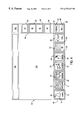
- the touch-sensitive screen is depicted in greater detail in FIG. 4 .
- the touch-sensitive screen 47 comprises, at the bottom, a first region 49 in which graphics 50 , 51 , 52 , 53 , 54 , 55 , 56 , 57 and 58 are permanently displayed.
- Each graphic 50 to 58 delimits on the touch-sensitive screen 47 an associated main control zone respectively bearing the reference numerals 60 to 68 , that is to say zones by means of which an operator responsible for monitoring the installation 1 , by bringing his finger into contact with the touch-sensitive screen 47 , input into the operating means 45 a command relating to a predetermined task.
- This first region 49 is strictly reserved for these main control zones 60 to 68 with the permanently-displayed associated graphics 50 to 58 .
- These main control zones 60 to 68 are permanently receptive to receiving a command from the operator. This is particularly advantageous when the means 39 control various tasks in parallel, because the operator can gain access to operating a task simply by activating the main control zone associated with this task.
- the touch-sensitive screen 47 also comprises, on its right-hand side as seen in FIG. 4, a second region 80 distinct from the first region 49 , in which there are displayed, depending on the task activated, graphics 81 , 82 , 83 and 84 which, in this figure, are depicted merely as boxes.
- These graphics 81 to 84 delimit secondary control zones respectively bearing the reference numerals 91 to 94 . These secondary control zones allow the operator to perform various operations relating to the specific task activated.
- the operating means further comprise means 70 for designating, on the touch-sensitive screen 47 , a main or secondary control zone that has been activated by an operator.
- the designation means 70 cause there to be displayed on the touch-sensitive screen 47 , for example, a coloured box 72 surrounding the activated main control zone 60 . In this way, the operator is always informed of the active task displayed on the screen.
- the touch-sensitive screen 47 comprises, at the top, a third region 100 , distinct from the first 49 and second 80 regions, which is reserved for displaying information relating to a main control zone activated by the operator.
- the zone 104 is enlarged and also comprises the region 80 .
- the graphic 50 shows a bell below which there is written “alarm”, and delimits the main control zone 60 relating to a task of managing and displaying alarms controlled by the means 39 as was described above. If an operator activates zone 60 , then the alarms picked up are displayed in the zone 104 of the touch-sensitive screen 47 , as depicted in FIG. 5 .
- graphics 81 to 84 delimit secondary control zones 91 to 94 relating to the management and display of the alarms are displayed on the screen. For example, activating the secondary zone 92 delimited by the graphic 82 allows a history of the alarms to be displayed.
- the graphic 51 in FIG. 4 shows displays with numerical values under which is written “pressure”. This graphic 51 delimits the main control zone 61 associated with the activation of a task relating to picking up the pressure and weight values measured by the sensors 31 and the balances 33 , and to displaying these values on the touch-sensitive screen 47 as is shown in FIG. 6 .
- the graphic 52 in FIG. 4 shows pipes and cylinders connected to them underneath which is written “diagram”. This graphic 52 delimits the main control zone 62 associated with the activation of a task relating to picking up the values of measurements measured by the sensors 31 and the balances 33 and to displaying on the touch-sensitive screen a block diagram of the device, this diagram being recorded in the memory storage means 48 , together with the values of measurements picked up, as is shown in FIG. 7 .
- the graphic 53 in FIG. 4 shows a gas supply installation (a gas cabinet) with cylinders and arrows signifying replacement of cylinders, below which is written “cylinders”.
- This graphic 53 delimits the main control zone 63 associated with the activation of two tasks.
- One of these tasks relates to the controlling of the valves in order to perform the flushing cycles and leak checks that are necessary each time before and after an empty cylinder is replaced by a full cylinder.
- the other task relates to the commands for the valves arranged in the pipes so as to switch from the distribution device 9 being supplied by one of the cylinders 5 or 7 to its being supplied by the other cylinder 7 or 5 .
- An example of the screens displayed when the zone 63 is activated is depicted in FIG. 8 .
- the graphic 55 in FIG. 4 shows pipes of a distribution device under which there is written “DD” (for distribution device).
- This graphic 55 delimits the main control zone 65 associated with the activation of a task relating to the evaluation of the values of measurements picked up by the sensors 31 A of the distribution device 9 A, placed in series with the device 9 of the installation 1 , and to the displaying on the touch-sensitive screen, of a block diagram of the device 9 A, recorded in the memory-storage means 48 , together with the values of measurements picked up by the sensors 31 A, as is shown in FIG. 9 .
- the use of the touch-sensitive screen 47 in the context of devices for distributing a working gas and of installations for supplying such a gas which are equipped with these devices substantially simplifies the work of the operators responsible for monitoring them and allows them to avoid a lengthy and costly training period.
Abstract
Description
Claims (28)
Applications Claiming Priority (2)
| Application Number | Priority Date | Filing Date | Title |
|---|---|---|---|
| FR9716491A FR2772881B1 (en) | 1997-12-24 | 1997-12-24 | DEVICE FOR DISTRIBUTING A WORKING GAS AND INSTALLATION FOR PROVIDING A WORKING GAS EQUIPPED WITH SUCH A DEVICE |
| FR9716491 | 1997-12-24 |
Publications (1)
| Publication Number | Publication Date |
|---|---|
| US6273129B1 true US6273129B1 (en) | 2001-08-14 |
Family
ID=9515121
Family Applications (1)
| Application Number | Title | Priority Date | Filing Date |
|---|---|---|---|
| US09/217,573 Expired - Fee Related US6273129B1 (en) | 1997-12-24 | 1998-12-21 | Device for distributing a working gas and installation for supplying a working gas that is equipped with such a device |
Country Status (8)
| Country | Link |
|---|---|
| US (1) | US6273129B1 (en) |
| EP (1) | EP0926429A1 (en) |
| JP (1) | JPH11316603A (en) |
| KR (1) | KR19990063368A (en) |
| CN (1) | CN1083965C (en) |
| FR (1) | FR2772881B1 (en) |
| SG (1) | SG70661A1 (en) |
| TW (1) | TW396258B (en) |
Cited By (10)
| Publication number | Priority date | Publication date | Assignee | Title |
|---|---|---|---|---|
| US20040084087A1 (en) * | 2002-10-30 | 2004-05-06 | Sanfilippo John E. | Apparatus and method for controlling and distributing gas flow |
| US20060022068A1 (en) * | 2004-08-02 | 2006-02-02 | Soria F J | Compact gassing lance |
| US20060213153A1 (en) * | 2005-03-03 | 2006-09-28 | Sanfilippo James J | Device and system for modified atmosphere packaging |
| CN106764436A (en) * | 2016-12-15 | 2017-05-31 | 武汉新芯集成电路制造有限公司 | A kind of special gas distributor box and its part exchanging method |
| US20170284887A1 (en) * | 2016-03-31 | 2017-10-05 | Konica Minolta Laboratory U.S.A., Inc. | Laser scanning leak detection and visualization apparatus |
| US9932806B2 (en) | 2014-04-28 | 2018-04-03 | Summit Esp, Llc | Apparatus, system and method for reducing gas to liquid ratios in submersible pump applications |
| EP3206002A4 (en) * | 2014-10-07 | 2018-05-23 | TLV Co., Ltd. | Fluid leakage data management apparatus and management system |
| US20180224068A1 (en) * | 2015-07-31 | 2018-08-09 | L'Air Liquide, Société Anonyme pour I'Etude et I'Exploitation des Procédés Georges Claude | Facility for distributing working gas |
| US20180320825A1 (en) * | 2015-07-31 | 2018-11-08 | L' Air Liquide, Société Anonyme pour l'Etude et l'Exploitation des Procédés Georges Claude | Pivotable touchscreen for a gas-distribution facility |
| US20190271137A1 (en) * | 2018-03-01 | 2019-09-05 | Armando Garcia Viveros | Home protection and control system |
Families Citing this family (5)
| Publication number | Priority date | Publication date | Assignee | Title |
|---|---|---|---|---|
| KR100776562B1 (en) | 2006-11-10 | 2007-11-16 | (주)지오필테크 | Purifying device for removing harmful gas and odor from gas analyzer with touch screen and operating method |
| CN101382236B (en) * | 2008-09-28 | 2012-09-05 | 张永华 | Fluid multi-pipeline collecting transmission and distribution control system and control method |
| CN102591373B (en) * | 2012-03-08 | 2013-07-10 | 中国计量学院 | Secondary series-connection enclosed-loop pressure-stabilizing air source with high accuracy for instrument |
| CN105114806B (en) * | 2015-09-17 | 2017-04-26 | 捷锐企业(上海)有限公司 | Double-side high-pressure gas cylinder gas supply switching system |
| CN109210380B (en) * | 2017-06-07 | 2020-10-16 | 北京东方华智石油工程有限公司 | Automatic natural gas distribution and transmission method and system |
Citations (12)
| Publication number | Priority date | Publication date | Assignee | Title |
|---|---|---|---|---|
| AU7186581A (en) | 1980-06-16 | 1981-12-24 | Forney International Inc. | Control system |
| US4430959A (en) | 1982-01-28 | 1984-02-14 | Toshiba Kikai Kabushiki Kaisha | Semiconductor vapor phase growing apparatus |
| EP0043201B1 (en) | 1980-06-16 | 1984-10-10 | Forney International, Inc. | Industrial process control system |
| US4646224A (en) * | 1983-12-05 | 1987-02-24 | L. R. Nelson Corporation | Sprinkler controller which computes sprinkler cycles based on inputted data |
| US4712191A (en) | 1982-08-11 | 1987-12-08 | U.S. Philips Corporation | Display system with nested information display |
| US4833592A (en) | 1986-09-01 | 1989-05-23 | Mitsubishi Denki Kabushiki Kaisha | Master station apparatus for remote supervisory control system with touch panel video display |
| US4866594A (en) | 1987-02-12 | 1989-09-12 | Mitel Corp. | Gas cylinder monitor and control system |
| US5170361A (en) * | 1990-01-16 | 1992-12-08 | Mark Reed | Fluid temperature, flow rate, and volume control system |
| US5521824A (en) * | 1992-12-07 | 1996-05-28 | Caterpillar Inc. | Method and apparatus for controlling an engine test apparatus using lead-lag control |
| DE29606594U1 (en) | 1996-04-11 | 1996-06-05 | Siemens Ag | Monitoring system for liquid gas containers, compressed gas containers or liquid gas or compressed gas pipelines |
| WO1997049099A1 (en) | 1996-06-20 | 1997-12-24 | Combustion Engineering, Inc. | Alarm significance mapping |
| US5742500A (en) * | 1995-08-23 | 1998-04-21 | Irvin; William A. | Pump station control system and method |
-
1997
- 1997-12-24 FR FR9716491A patent/FR2772881B1/en not_active Expired - Fee Related
-
1998
- 1998-12-09 SG SG1998005370A patent/SG70661A1/en unknown
- 1998-12-14 EP EP19980403140 patent/EP0926429A1/en not_active Withdrawn
- 1998-12-18 TW TW87121140A patent/TW396258B/en not_active IP Right Cessation
- 1998-12-21 US US09/217,573 patent/US6273129B1/en not_active Expired - Fee Related
- 1998-12-22 JP JP36474498A patent/JPH11316603A/en active Pending
- 1998-12-23 KR KR1019980057593A patent/KR19990063368A/en not_active Application Discontinuation
- 1998-12-24 CN CN98126036A patent/CN1083965C/en not_active Expired - Fee Related
Patent Citations (12)
| Publication number | Priority date | Publication date | Assignee | Title |
|---|---|---|---|---|
| AU7186581A (en) | 1980-06-16 | 1981-12-24 | Forney International Inc. | Control system |
| EP0043201B1 (en) | 1980-06-16 | 1984-10-10 | Forney International, Inc. | Industrial process control system |
| US4430959A (en) | 1982-01-28 | 1984-02-14 | Toshiba Kikai Kabushiki Kaisha | Semiconductor vapor phase growing apparatus |
| US4712191A (en) | 1982-08-11 | 1987-12-08 | U.S. Philips Corporation | Display system with nested information display |
| US4646224A (en) * | 1983-12-05 | 1987-02-24 | L. R. Nelson Corporation | Sprinkler controller which computes sprinkler cycles based on inputted data |
| US4833592A (en) | 1986-09-01 | 1989-05-23 | Mitsubishi Denki Kabushiki Kaisha | Master station apparatus for remote supervisory control system with touch panel video display |
| US4866594A (en) | 1987-02-12 | 1989-09-12 | Mitel Corp. | Gas cylinder monitor and control system |
| US5170361A (en) * | 1990-01-16 | 1992-12-08 | Mark Reed | Fluid temperature, flow rate, and volume control system |
| US5521824A (en) * | 1992-12-07 | 1996-05-28 | Caterpillar Inc. | Method and apparatus for controlling an engine test apparatus using lead-lag control |
| US5742500A (en) * | 1995-08-23 | 1998-04-21 | Irvin; William A. | Pump station control system and method |
| DE29606594U1 (en) | 1996-04-11 | 1996-06-05 | Siemens Ag | Monitoring system for liquid gas containers, compressed gas containers or liquid gas or compressed gas pipelines |
| WO1997049099A1 (en) | 1996-06-20 | 1997-12-24 | Combustion Engineering, Inc. | Alarm significance mapping |
Cited By (17)
| Publication number | Priority date | Publication date | Assignee | Title |
|---|---|---|---|---|
| US20060102736A1 (en) * | 2002-10-30 | 2006-05-18 | Sanfilippo John E | Apparatus and method for controlling and distributing gas flow |
| US20040084087A1 (en) * | 2002-10-30 | 2004-05-06 | Sanfilippo John E. | Apparatus and method for controlling and distributing gas flow |
| US20060022068A1 (en) * | 2004-08-02 | 2006-02-02 | Soria F J | Compact gassing lance |
| US7198206B2 (en) | 2004-08-02 | 2007-04-03 | Clear Lam, Inc. | Compact gassing lance |
| US20060213153A1 (en) * | 2005-03-03 | 2006-09-28 | Sanfilippo James J | Device and system for modified atmosphere packaging |
| US9932806B2 (en) | 2014-04-28 | 2018-04-03 | Summit Esp, Llc | Apparatus, system and method for reducing gas to liquid ratios in submersible pump applications |
| EP3206002A4 (en) * | 2014-10-07 | 2018-05-23 | TLV Co., Ltd. | Fluid leakage data management apparatus and management system |
| EP3739413A1 (en) * | 2014-10-07 | 2020-11-18 | TLV Co., Ltd. | Fluid leakage data management apparatus and method for deducing pipe connection |
| US11422053B2 (en) | 2014-10-07 | 2022-08-23 | Tlv Co., Ltd. | Fluid leakage data management apparatus and management system |
| US20180224068A1 (en) * | 2015-07-31 | 2018-08-09 | L'Air Liquide, Société Anonyme pour I'Etude et I'Exploitation des Procédés Georges Claude | Facility for distributing working gas |
| US20180320825A1 (en) * | 2015-07-31 | 2018-11-08 | L' Air Liquide, Société Anonyme pour l'Etude et l'Exploitation des Procédés Georges Claude | Pivotable touchscreen for a gas-distribution facility |
| US10823336B2 (en) * | 2015-07-31 | 2020-11-03 | L'Air Liquide, Société Anonyme pour l'Etude et l'Exploitation des Procédés Georges Claude | Pivotable touchscreen for a gas-distribution facility |
| US20170284887A1 (en) * | 2016-03-31 | 2017-10-05 | Konica Minolta Laboratory U.S.A., Inc. | Laser scanning leak detection and visualization apparatus |
| US10634575B2 (en) * | 2016-03-31 | 2020-04-28 | Konica Minolta Laboratory U.S.A., Inc. | Laser scanning leak detection and visualization apparatus |
| CN106764436A (en) * | 2016-12-15 | 2017-05-31 | 武汉新芯集成电路制造有限公司 | A kind of special gas distributor box and its part exchanging method |
| CN106764436B (en) * | 2016-12-15 | 2018-09-07 | 武汉新芯集成电路制造有限公司 | A kind of spy's gas distributor box and its part exchanging method |
| US20190271137A1 (en) * | 2018-03-01 | 2019-09-05 | Armando Garcia Viveros | Home protection and control system |
Also Published As
| Publication number | Publication date |
|---|---|
| KR19990063368A (en) | 1999-07-26 |
| CN1083965C (en) | 2002-05-01 |
| JPH11316603A (en) | 1999-11-16 |
| TW396258B (en) | 2000-07-01 |
| SG70661A1 (en) | 2000-02-22 |
| FR2772881B1 (en) | 2000-01-14 |
| CN1221090A (en) | 1999-06-30 |
| EP0926429A1 (en) | 1999-06-30 |
| FR2772881A1 (en) | 1999-06-25 |
Similar Documents
| Publication | Publication Date | Title |
|---|---|---|
| US6273129B1 (en) | Device for distributing a working gas and installation for supplying a working gas that is equipped with such a device | |
| US6288650B2 (en) | Device and method for monitoring the operation of an industrial installation | |
| US4866594A (en) | Gas cylinder monitor and control system | |
| AU640585B2 (en) | Leak protected vessel | |
| US7174228B2 (en) | Field device with display | |
| CN201373383Y (en) | Water level display and control device of marine supercharged boiler | |
| EP2092498A2 (en) | Enclosure system allowing for hot work within the vicinity of flammable and combustible material | |
| US10823336B2 (en) | Pivotable touchscreen for a gas-distribution facility | |
| KR100686941B1 (en) | Integrated Control and Safety Management System for a LNG Storage Tank | |
| CN104678874B (en) | A kind of blowing type liquid level telemetry system | |
| JP2899349B2 (en) | Sensor inspection device | |
| KR200266364Y1 (en) | The real-time gas monitoring device of gas supply system | |
| KR102082858B1 (en) | Enclosed space low power monitoring device and method | |
| KR200255564Y1 (en) | Monitoring control device for chlorinator | |
| KR20230052781A (en) | Fire extinguishing System | |
| JPS60122499A (en) | Alarm monitor | |
| JPH1027291A (en) | Alarm signal processor and its method | |
| KR200306982Y1 (en) | Changeover valve | |
| KR101741532B1 (en) | pump control device for ship | |
| JP2004257578A (en) | Boiler room monitoring device | |
| KR20230112854A (en) | Explosion proof inhalation type gas detector | |
| JP2008164281A (en) | Boiler room monitor | |
| JPH06300656A (en) | Gas leak detector | |
| KR19980060983U (en) | Liquid Crystal Display of Remote Sensing Remote Device | |
| JPH02126109A (en) | Level display device |
Legal Events
| Date | Code | Title | Description |
|---|---|---|---|
| AS | Assignment |
Owner name: L'AIR LIQUIDE, SOCIETE ANONYME POUR L'ETUDE ET L'E Free format text: ASSIGNMENT OF ASSIGNORS INTEREST;ASSIGNORS:CHAVAND, ANDRE;BOURGEOIS, MARCH;FANJAT, NORBERT;REEL/FRAME:009820/0940;SIGNING DATES FROM 19990211 TO 19990219 Owner name: ALPES SYSTEME AUTOMATION, FRANCE Free format text: ASSIGNMENT OF ASSIGNORS INTEREST;ASSIGNORS:CHAVAND, ANDRE;BOURGEOIS, MARCH;FANJAT, NORBERT;REEL/FRAME:009820/0940;SIGNING DATES FROM 19990211 TO 19990219 Owner name: ETABLISSEMENT LABIELLE, FRANCE Free format text: ASSIGNMENT OF ASSIGNORS INTEREST;ASSIGNORS:CHAVAND, ANDRE;BOURGEOIS, MARCH;FANJAT, NORBERT;REEL/FRAME:009820/0940;SIGNING DATES FROM 19990211 TO 19990219 |
|
| AS | Assignment |
Owner name: L'AIR LIQUIDE, SOCIETE ANONYME POUR L'ETUDE ET L'E Free format text: CORRECTIVE ASSIGNMENT TO CORRECT THE SPELLING OF THE CONVEYING PARTY, FILED ON 03/09/1999, RECORDED ON REEL 009820 FRAME 0940;ASSIGNORS:CHAVAND, ANDRE;BOURGEOIS, MARC;FANJAT, NORBERT;REEL/FRAME:010598/0155;SIGNING DATES FROM 19990211 TO 19990219 Owner name: ALPES SYSTEME AUTOMATION, FRANCE Free format text: CORRECTIVE ASSIGNMENT TO CORRECT THE SPELLING OF THE CONVEYING PARTY, FILED ON 03/09/1999, RECORDED ON REEL 009820 FRAME 0940;ASSIGNORS:CHAVAND, ANDRE;BOURGEOIS, MARC;FANJAT, NORBERT;REEL/FRAME:010598/0155;SIGNING DATES FROM 19990211 TO 19990219 Owner name: ETABLISSEMENT LABIELLE, FRANCE Free format text: CORRECTIVE ASSIGNMENT TO CORRECT THE SPELLING OF THE CONVEYING PARTY, FILED ON 03/09/1999, RECORDED ON REEL 009820 FRAME 0940;ASSIGNORS:CHAVAND, ANDRE;BOURGEOIS, MARC;FANJAT, NORBERT;REEL/FRAME:010598/0155;SIGNING DATES FROM 19990211 TO 19990219 |
|
| REMI | Maintenance fee reminder mailed | ||
| LAPS | Lapse for failure to pay maintenance fees | ||
| STCH | Information on status: patent discontinuation |
Free format text: PATENT EXPIRED DUE TO NONPAYMENT OF MAINTENANCE FEES UNDER 37 CFR 1.362 |
|
| FP | Lapsed due to failure to pay maintenance fee |
Effective date: 20050814 |