US6261418B1 - Headbox with flexible support plates - Google Patents
Headbox with flexible support plates Download PDFInfo
- Publication number
- US6261418B1 US6261418B1 US09/411,659 US41165999A US6261418B1 US 6261418 B1 US6261418 B1 US 6261418B1 US 41165999 A US41165999 A US 41165999A US 6261418 B1 US6261418 B1 US 6261418B1
- Authority
- US
- United States
- Prior art keywords
- nozzle
- running direction
- machine
- machine running
- wall
- Prior art date
- Legal status (The legal status is an assumption and is not a legal conclusion. Google has not performed a legal analysis and makes no representation as to the accuracy of the status listed.)
- Expired - Fee Related
Links
Images


Classifications
-
- D—TEXTILES; PAPER
- D21—PAPER-MAKING; PRODUCTION OF CELLULOSE
- D21F—PAPER-MAKING MACHINES; METHODS OF PRODUCING PAPER THEREON
- D21F1/00—Wet end of machines for making continuous webs of paper
- D21F1/02—Head boxes of Fourdrinier machines
- D21F1/024—Details of the feed chamber
-
- D—TEXTILES; PAPER
- D21—PAPER-MAKING; PRODUCTION OF CELLULOSE
- D21F—PAPER-MAKING MACHINES; METHODS OF PRODUCING PAPER THEREON
- D21F1/00—Wet end of machines for making continuous webs of paper
- D21F1/02—Head boxes of Fourdrinier machines
-
- D—TEXTILES; PAPER
- D21—PAPER-MAKING; PRODUCTION OF CELLULOSE
- D21F—PAPER-MAKING MACHINES; METHODS OF PRODUCING PAPER THEREON
- D21F1/00—Wet end of machines for making continuous webs of paper
- D21F1/02—Head boxes of Fourdrinier machines
- D21F1/026—Details of the turbulence section
-
- D—TEXTILES; PAPER
- D21—PAPER-MAKING; PRODUCTION OF CELLULOSE
- D21F—PAPER-MAKING MACHINES; METHODS OF PRODUCING PAPER THEREON
- D21F1/00—Wet end of machines for making continuous webs of paper
- D21F1/02—Head boxes of Fourdrinier machines
- D21F1/028—Details of the nozzle section
Definitions
- the present invention relates to a headbox for a paper-making machine with a nozzle extending transverse to the machine running direction across the machine width.
- the headbox has a lower and an upper continuous wall each extending across the machine width.
- the lower nozzle wall is normally supported by a run-in table provided as a continuous weldment.
- a run-in table provided as a continuous weldment.
- the invention resides in creating a headbox of the type mentioned above which continuously guarantees as parallel an outlet gap as possible practically independently of the respective operating conditions, having the most cost-effective design possible, simple operation, and minimal maintenance expense.
- the lower nozzle wall is supported by several separate supporting elements distributed across the machine width on a foundation. These supporting elements are designed to be non-rigid or flexible to bending transverse to the machine running direction.
- the supporting elements essentially carry the entire headbox. In the case of a temperature-induced change in length of the lower nozzle wall, these supporting elements give way correspondingly in a direction transverse to the machine running direction.
- the lower nozzle wall remains sufficiently even in the case of a change in temperature and/or pressure. Therefore, the heating system that compensates for the thermal bending of the lower nozzle wall that has been conventional until now can be eliminated.
- the individual supporting elements can extend at least to some degree in a generally vertical manner, i.e., perpendicular to the lower nozzle wall.
- the individual supporting elements are formed at least partially by disks, i.e., stud bolts or the like, extending parallel to the machine running direction.
- the individual supporting elements can be connected directly to the foundation by a base plate and/or a pedestal.
- the supporting elements can be connected to the lower nozzle wall, for example.
- the supporting elements are connected to the supporting plate.
- At least one diagonal or transverse brace is provided suitably in a center area, as viewed transverse to the machine running direction, between successive supporting elements.
- Another alternative solution according to the invention or one in combination with the preceding solution of the above objective includes a headbox of the type mentioned previously in which the upper nozzle wall can be swiveled around an axis extending transverse to the machine running direction and is connected by several separate supporting members, distributed across the machine width, with a transverse bar attached above the swivel axis. These supporting members are to be non-rigid or flexible to bending transverse to the machine running direction (see claim 10 ).
- the headbox can be provided in particular with a central component which includes a lower arm formed by the lower nozzle wall or the supporting plate allocated to the nozzle, an upper arm that is preferably parallel to the nozzle, an inlet-side first central part and a second central part behind the first central part in the machine running direction.
- the upper arm and the two central parts are arranged between this upper arm and the lower arm preferably forming supporting members of a turbulence generator.
- the transverse bar be connected to the central component by at least one stroke element and no more than three stroke elements, and in particular by only one stroke element or by two stroke elements.
- the individual supporting members extend at least to some extent in a generally vertical manner, i.e., perpendicular to the upper nozzle wall.
- the individual supporting members are preferably formed at least partially by disks parallel to the machine running direction.
- the transverse bar can be formed by sheet metal standing on edge or by a hollow beam.
- a headbox In a headbox according to the invention, provisions are made for the upper arm and the rear or downstream second central part of the central component to each be segmented transverse to the machine running direction.
- the inlet-side first central part of the central component and the lower nozzle wall are each designed to be continuous transverse to the machine running direction.
- the central component is thus formed by a partially segmented C-shaped clamp, where basically only those parts bordering the material guiding areas are not segmented, i.e., are formed continuously in the crosswise direction.
- This third solution according to the invention can also be provided alternatively or in combination with the two previous solutions according to the invention. If in combination with the two previous solutions, both a combination with the first or second solution as well as a combination of all three solutions are conceivable.
- the stationary supporting plate also be segmented transverse to the machine running direction.
- the upper nozzle wall is swiveled by a hinge around an axis extending transverse to the machine running direction
- a continuous hinge bearing is provided extending transverse to the machine running direction on the rear or downstream end of the upper arm of the central component in the machine running direction.
- This hinge bearing can always have a material reduction in the area between the individual segments of the adjacent upper arm.
- the division of the segments of the upper arm of the central component defined by the distances from segment center to segment center is equal to the division of the segments of the rear or downstream second central part of the central component.
- the parallelism of the outlet gap can be assured under substantially all operating conditions that are possible in practice. Accordingly, deformations of the upper and the lower nozzle wall under varying pressure in the nozzle and/or under varying material temperature are at least essentially excluded. If the nozzle walls are pressed apart under hydrostatic pressure during operation, the resulting expansion forces are transmitted rather uniformly across the machine width by way of the cited numerous supporting elements or the supporting members. A deflection of the nozzle walls is, therefore, avoided. In addition, an extremely cost-effective design is realized, i.e., particularly lower expenses for material and manufacture (such as processing) as well as for control and regulation equipment. Lower expenses for maintenance are also achieved along with simpler handling during operation.
- the dimensions of the component cross-section can be equal for different headboxes with different machine widths. This simplifies the creation of drawings and manufacture. Only the supporting elements have to be dimensioned according to the maximum pressure prevailing in the nozzle.
- One or more, e.g., two, hydraulic cylinders and linear stroke flow dividers can be provided as the drive for this type of displaceable lower nozzle wall.
- MLH series linear stroke flow dividers made by the company Jahns-Regulatoren GmbH, located in D-63069 Offenbach, Germany, can be used, as they were described in a corresponding Jahns-Regulatoren GmbH publication in March 1997.
- One or two additional hydraulic cylinders can be provided in the center area in the case of greater machine widths.
- a headbox for a paper-making machine comprising a nozzle extending transversely to a machine running direction, across a machine width.
- the nozzle has a lower and an upper continuous wall, each extending across the machine width.
- Several separate supporting elements are distributed across the machine width on a foundation for supporting the lower wall on the nozzle.
- the supporting elements are non-rigid.
- the supporting elements are flexible to permit bending in a direction transverse to the machine running direction and extend at least to some extent vertically, and perpendicularly to the lower nozzle wall.
- the individual supporting elements comprise, at least partially, disks, stud bolts, or the like, disposed in a direction parallel to the machine running direction.
- the supporting elements are connected directly to the foundation. Alternatively, the supporting elements are connected to the foundation by at least one of, a base plate or a pedestal. The supporting elements are connected to the lower wall of the nozzle.
- the lower wall of the nozzle is moveable on a stationary supporting plate in the machine running direction and the supporting elements are connected to the supporting plate.
- At least one of, a diagonal brace or transverse brace are provided between successive supporting elements in a center area, as viewed in a direction transverse to the machine running direction.
- the upper wall of the nozzle is pivotable around a swivel axis extending transversely to the machine running direction, and further comprises a transverse bar attached above the swivel axis.
- Several separate supporting members are distributed across the machine width. The supporting members connect the upper wall with the transverse bar.
- the supporting members are non-rigid and may be flexible to permit bending in a direction transverse to the machine running direction.
- a central component comprised of one of, a lower arm formed by the lower wall of the nozzle or the supporting plate allocated to it, an upper arm parallel to the central component, an inlet-side first central part and a second central part behind the first central part in the machine running direction.
- the upper arm and the two central parts arranged between the upper arm and the lower arm comprise supporting members of a turbulence generator.
- At least one stroke element but no more than three stroke elements connect the transverse bar to the central component.
- a single, or two stroke elements are provided.
- the at least one stroke element comprises a threaded spindle, or a hydraulic cylinder.
- the individual supporting members extend at least to some extent vertically, and in a direction perpendicular to the upper wall of the nozzle.
- the individual supporting members comprise, at least partially, disks disposed in a direction parallel to the machine running direction.
- the transverse bar comprises a sheet metal standing on its edge.
- the transverse bar may comprise a hollow beam.
- the division of the supporting elements and the supporting members is defined by the distances from one of, element or member center to, one of, element or member center, and is equal to the division of the segments of the central component.
- a headbox for a paper-making machine comprises a nozzle extending transversely to a machine running direction across a machine width.
- the nozzle has a lower and an upper continuous wall, each extending across the machine width.
- a central component comprised of one of, a lower arm formed by the lower wall of the nozzle or the supporting plate is allocated to it.
- An upper arm on the central component extends in a direction parallel to the central component.
- the upper arm and the two central parts between the upper arm and the lower arm comprise supporting members of a turbulence generator, the upper arm and the second central part being each segmented in a direction transverse to the machine running direction to define segments thereon.
- the inlet-side first central part and the lower wall on the nozzle are each continuous in a direction transverse to the machine running direction.
- the lower wall on the nozzle wall is moveable on a stationary supporting plate in the machine running direction and the stationary supporting plate is segmented transversely to the machine running direction.
- the headbox further comprises a hinge, the upper wall on the nozzle being pivotable on the hinge around an axis extending transversely to the machine running direction.
- a continuous hinge bearing extending transversely to the machine running direction, is provided on a rear end of the upper arm of the central component in the machine running direction. The hinge bearing has a material reduction in the area between the individual segments of the adjacent upper arm.
- the division of the segments of the upper arm of the central component defined by the distances from segment center to segment center is approximately equal to the division of the segments of the second central part of the central component.
- a headbox for a paper-making machine, comprises a nozzle extending transversely to a machine running direction across a machine width.
- the nozzle has a lower and an upper continuous wall, each extending across the machine width.
- the supporting elements are non-rigid.
- At least one of, a diagonal brace or transverse brace are provided between successive supporting elements in a center area, as viewed in a direction transverse to the machine running direction.
- the upper wall of the nozzle is pivotable around a swivel axis extending transversely to the machine running direction.
- a transverse bar is attached above the swivel axis.
- the supporting members connect the upper wall with the transverse bar.
- the supporting members are non-rigid.
- a central component comprised of one of, a lower arm formed by the lower wall of the nozzle or the supporting plate is allocated to the nozzle.
- the upper arm and the two central parts arranged between the upper arm and the lower arm comprise supporting members of a turbulence generator. At least one stroke element connects the transverse bar to the central component.
- a headbox for a paper-making machine comprising a nozzle extending transversely to a machine running direction across a machine width.
- the nozzle has a lower and an upper continuous wall, each extending across the machine width.
- a central component comprised of one of, a lower arm formed by the lower wall of the nozzle or the supporting plate is allocated to it.
- An upper arm on the central component extends in a direction parallel to the central component.
- An inlet-side first central part is provided on the central component.
- a second central part is located behind the first central part in the machine running direction.
- the upper arm and the two central parts between the upper arm and the lower arm comprise supporting members of a turbulence generator, the upper arm and the second central part being each segmented in a direction transverse to the machine running direction to define segments thereon.
- the inlet-side first central part and the lower wall on the nozzle are each continuous in a direction transverse to the machine running direction.
- the upper wall on the nozzle is pivotable on a hinge around an axis extending transversely to the machine running direction.
- a continuous hinge bearing, extending transversely to the machine running direction, is provided on a rear end of the upper arm of the central component in the machine running direction.
- FIG. 1 shows a schematic partial section of a side view of a first embodiment of a headbox for an endless wire former
- FIG. 2 is a schematic sectional representation of the headbox cut along Line II—II in FIG. 1;
- FIG. 3 is a schematic perspective representation of the central component of a headbox whose lower nozzle wall cannot be displaced;
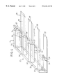
- FIG. 4 is a schematic perspective representation of the central component of a headbox with a lower nozzle wall that can be displaced in the machine running direction;
- FIG. 5 is a schematic partial section of a side view of another embodiment of a headbox for a twin wire former.
- FIGS. 1 and 2 show a purely schematic representation of a first embodiment of a headbox 10 for an endless wire former of a paper machine.
- the headbox 10 includes a nozzle 12 , extending transverse to the machine running direction L across the machine width, with a lower and an upper continuous wall 14 and 16 each extending across the machine width.
- the upper nozzle wall 16 can be swiveled by a hinge 18 around an axis A extending transverse to the machine running direction L.
- the lower nozzle wall 14 can be displaced on a stationary supporting plate 20 in the machine running direction L.
- a central component 22 of the headbox 10 includes a lower arm formed in the present embodiment by the supporting plate 20 , an upper arm 24 that is preferably at least essentially parallel to it, an upstream first central part 26 and a second central part 28 further behind it in the machine running direction L or downstream.
- the upper arm 24 and the two central parts 26 , 28 arranged between this upper arm and the lower arm 20 preferably form supporting members of a turbulence generator.
- this lower nozzle wall or a corresponding section thereof can be added to the central component 22 .
- the fiber suspension 32 is fed to the central component 22 by a lateral distributing pipe 30 , for example.
- the central component 22 which is constructed as a turbulence generator, is provided with several graduated diffusers or with continuously variable turbulence pipes.
- the flow is guided to an outlet gap 36 by way of the lower nozzle wall 14 and the upper nozzle wall 16 as well as the lateral delimitations 34 , such as side shields or the like, for example.
- the material stream that corresponds to the machine width exiting from the outlet gap 36 reaches the area of the breast roll 38 on a continuously circulating screen belt 40 .
- the stationary supporting plate 20 for the lower nozzle wall 14 or a stationary nozzle wall is supported by several separate supporting elements 42 distributed across the machine width on a foundation 44 .
- the supporting elements 42 are designed to be non-rigid or flexible to bending transverse to the machine running direction L.
- the individual supporting elements extend at least to some extent generally vertically, i.e., perpendicular to the lower nozzle wall 14 or the supporting plate 20 .
- these supporting elements 42 are formed by disks (i.e. plates) parallel to the machine running direction L.
- disks i.e. plates
- they can also be formed by stud bolts or the like, for example.
- the supporting elements 42 are connected to the foundation 44 by a pedestal 46 made of concrete, for example. Basically, these supporting elements 42 can also be connected directly to the foundation 44 , however.
- the supporting elements 42 are each connected to the supporting plate 20 on the other end. In the case of a non-displaceable lower nozzle wall formed as one piece with the supporting plate, the supporting elements would be connected with the non-displaceable lower nozzle wall.
- a diagonal brace 48 is provided between the two center supporting elements 42 , as viewed transverse to the machine running direction L.
- a transverse bar connected directly to the supporting plate 20 is missing.
- a heating system to compensate for the thermal bending of the supporting plate 20 or the nozzle wall 14 could also be eliminated.
- Heating devices (not shown) to change the height of at least one of the supporting elements 42 are conceivable, if need be, and namely in the case of a deformation of the foundation 44 or the pedestal 46 (which is hardly to be expected, however).
- the upper nozzle wall 16 that can be swiveled around lateral axis A by way of the hinge 18 is connected by several separate supporting members 50 distributed across the machine width with a transverse bar 52 attached above the swivel axis A.
- These supporting members 50 are again designed to be non-rigid or flexible to bending transverse to the machine running direction L.
- the individual supporting members 50 extend vertically, i.e., perpendicular to the upper nozzle wall 16 .
- the individual supporting members 50 are again formed by disks (i.e. plates) parallel to the machine running direction L.
- Sheet metal standing on edge or a hollow beam can be provided as the transverse bar 52 , for example (see FIG. 1 in particular).
- One or more stroke elements 54 are coupled by way of an articulated axis 56 or 58 with the central component 22 on one side and with the traverse bar 52 on the other side.
- the upper nozzle wall 16 can be swiveled around the axis A in the direction of the arrow F (see FIG. 1) by these stroke elements 54 .
- the stroke elements 54 one can be dealing with threaded spindles, hydraulic cylinders and/or the like, for example.
- Stroke elements 60 are again provided for the linear displacement of the lower nozzle wall 14 .
- the drive for the lower nozzle wall 14 can take place by two hydraulic cylinders 60 and a linear stroke flow divider provided on two opposite sides, such as those marketed by the company Jahns-Regulatoren GmbH.
- One or two additional hydraulic cylinders can be provided in the center area in the case of greater machine widths.
- the upper arm 24 and the rear second central part 28 of the central component 22 in machine running direction L are each segmented transverse to the machine running direction L.
- the inlet-side first central part 26 of the central component 22 and the supporting plate 20 for the displaceable lower nozzle wall 14 are each designed to be continuous transverse to the machine running direction L.
- FIG. 3 shows a schematic perspective representation of the central component 22 of a headbox. If the lower wall 14 (see FIG. 1) is not displaceable, it can be designed to be a single piece together with the supporting plate 20 .
- FIG. 4 again shows a schematic perspective representation of the central component of a headbox provided for a lower nozzle wall 14 (omitted from FIG. 4) that is displaceable in the machine running direction L on a stationary supporting plate 20 (also see FIGS. 1 and 2 ).
- the stationary supporting plate 20 is also segmented transverse to the machine running direction L.
- a central component 22 is thus formed by a partially segmented C-shaped clamp. Hydrostatic pressure acting on the nozzle wall 14 and 16 results in tensile forces which pass through the segments 28 ′ of the second central part 28 , and pressure forces which pass through the first central part 26 .
- a continuous hinge bearing 62 of the hinge 18 (see also FIG. 1) extending transverse to the machine running direction L is provided on the rear end of the upper arm 24 of the central component 22 in the machine running direction L, into which a counter element 64 (see FIG. 1) provided on the upper nozzle wall 16 engages.
- the hinge bearing 62 has a constant cross-section transverse to the machine running direction L.
- the hinge bearing in the case of the central component 22 shown in FIG. 4 always has a material reduction 66 in the area between the individual segments 24 ′ of the adjacent upper arm 24 .
- the hinge bearing 62 it is also conceivable, for example, for the hinge bearing 62 to be composed of a continuous lower part and of several (therefore segmented) upper parts according to FIG. 4 .
- the division of the segments 24 ′ of the upper arm 24 of the central component 22 defined by the distances from segment center to segment center is equal in both the embodiments depicted in FIGS. 3 and 4 to the division of the segments 28 ′ of the rear second central part 28 of the central component in the machine running direction L.
- the division of the supporting elements 42 and the supporting members 50 defined by the distances from element or member center to element or member center is equal to the division of the segments 20 ′, 24 ′, 28 ′ of the central component 22 .
- the segments 24 ′ and 28 ′ of the central component 22 are provided in the form of individual blocks distributed across the machine width. This also applies (in the case of FIG. 4) to the upper parts of the hinge bearing 62 .
- FIG. 5 shows a schematic partial section of a side view of another embodiment of a headbox 10 for a twin wire former.
- the fiber suspension is fed to an admission part 67 connected in series with the central component 22 by way of line 68 and the lateral distributing pipe 30 such that a consistency regulator sectioned transverse to the machine running direction L can be provided.
- the material stream in the machine width exiting from the outlet gap 36 reaches an inlet gap 74 formed between two screen belts 70 , 72 .
- the headbox 10 in the exemplary embodiments shown in FIGS. 1 and 2 is oriented essentially horizontally
- the headbox 10 in the embodiment depicted in FIG. 5 is oriented with its outlet gap 36 diagonally upwards in the inlet gap 74 formed between the two screen belts 70 , 72 .
- this headbox 10 again has at least essentially the same structure as the exemplary embodiments according to FIGS. 1 through 4.
Abstract
Description
Claims (27)
Applications Claiming Priority (6)
| Application Number | Priority Date | Filing Date | Title |
|---|---|---|---|
| DE19845722A DE19845722A1 (en) | 1998-10-05 | 1998-10-05 | Papermaking stock inlet jet structure |
| DE29823639U DE29823639U1 (en) | 1998-10-05 | 1998-10-05 | Papermaking stock inlet jet structure |
| DE29823639 | 1998-10-05 | ||
| DE19845722 | 1998-10-05 | ||
| DE19927241 | 1999-06-15 | ||
| DE19927241A DE19927241A1 (en) | 1998-10-05 | 1999-06-15 | Papermaking stock inlet jet structure |
Publications (1)
| Publication Number | Publication Date |
|---|---|
| US6261418B1 true US6261418B1 (en) | 2001-07-17 |
Family
ID=27218713
Family Applications (1)
| Application Number | Title | Priority Date | Filing Date |
|---|---|---|---|
| US09/411,659 Expired - Fee Related US6261418B1 (en) | 1998-10-05 | 1999-10-04 | Headbox with flexible support plates |
Country Status (1)
| Country | Link |
|---|---|
| US (1) | US6261418B1 (en) |
Cited By (1)
| Publication number | Priority date | Publication date | Assignee | Title |
|---|---|---|---|---|
| US20100227073A1 (en) * | 2009-03-03 | 2010-09-09 | United States Gypsum Company | Process and apparatus for feeding cementitious slurry for fiber-reinforced structural cement panels |
Citations (13)
| Publication number | Priority date | Publication date | Assignee | Title |
|---|---|---|---|---|
| US1775905A (en) | 1928-03-20 | 1930-09-16 | American Voith Contact Co Inc | Stock inlet for paper machines |
| US3309264A (en) * | 1964-01-17 | 1967-03-14 | Beloit Corp | Flow distributor for a papermaking machine |
| US3313681A (en) | 1964-08-27 | 1967-04-11 | Beloit Corp | Headbox with bottom wall having controllable deflection |
| GB1145299A (en) * | 1966-01-04 | 1969-03-12 | Valmet Oy | Improvements in methods of and arrangements for regulating or eliminating downward deflections of the aprons of headbox slices in paper-machines |
| US3977938A (en) * | 1973-05-21 | 1976-08-31 | Dominion Engineering Works, Limited | Support beam for the rectifier section of a headbox |
| GB1595560A (en) | 1977-03-29 | 1981-08-12 | Beloit Corp | Headbox structures |
| US4406741A (en) * | 1980-12-17 | 1983-09-27 | Valmet Oy | Adjustable headbox for a paper machine |
| DE3628699A1 (en) | 1986-08-23 | 1988-03-03 | Voith Gmbh J M | FABRIC DRAIN |
| DE3723922A1 (en) | 1987-07-18 | 1989-01-26 | Bruderhaus Maschf Neue | TURBULENCE GENERATOR FOR THE FABRIC OUTLET OF A PAPER MACHINE |
| US4923569A (en) | 1988-05-27 | 1990-05-08 | Valmet-Ahlstrom, Inc. | Hydraulic headbox with air attenuation chamber located under the stock flow route |
| DE4106764A1 (en) | 1991-02-22 | 1992-08-27 | Voith Gmbh J M | Stock inlet channel wall, secured to the beam only by rows of rods - holds wall without bending, maintaining constant pulp flow to paper-making machine |
| EP0631011A1 (en) | 1993-06-03 | 1994-12-28 | Hans-Joachim Dr. Schultz | Headbox for a papermaking machine |
| US5565064A (en) * | 1993-08-28 | 1996-10-15 | J.M. Voith Gmbh | Paper machine wet forming section and method of operation thereof |
-
1999
- 1999-10-04 US US09/411,659 patent/US6261418B1/en not_active Expired - Fee Related
Patent Citations (15)
| Publication number | Priority date | Publication date | Assignee | Title |
|---|---|---|---|---|
| US1775905A (en) | 1928-03-20 | 1930-09-16 | American Voith Contact Co Inc | Stock inlet for paper machines |
| US3309264A (en) * | 1964-01-17 | 1967-03-14 | Beloit Corp | Flow distributor for a papermaking machine |
| US3313681A (en) | 1964-08-27 | 1967-04-11 | Beloit Corp | Headbox with bottom wall having controllable deflection |
| GB1145299A (en) * | 1966-01-04 | 1969-03-12 | Valmet Oy | Improvements in methods of and arrangements for regulating or eliminating downward deflections of the aprons of headbox slices in paper-machines |
| US3977938A (en) * | 1973-05-21 | 1976-08-31 | Dominion Engineering Works, Limited | Support beam for the rectifier section of a headbox |
| GB1595560A (en) | 1977-03-29 | 1981-08-12 | Beloit Corp | Headbox structures |
| US4406741A (en) * | 1980-12-17 | 1983-09-27 | Valmet Oy | Adjustable headbox for a paper machine |
| DE3628699A1 (en) | 1986-08-23 | 1988-03-03 | Voith Gmbh J M | FABRIC DRAIN |
| EP0323468B1 (en) | 1986-08-23 | 1990-06-06 | J.M. Voith GmbH | Headbox |
| US5304285A (en) | 1986-08-23 | 1994-04-19 | J.M. Voith Gmbh | Stock-inlet for papermaking machine |
| DE3723922A1 (en) | 1987-07-18 | 1989-01-26 | Bruderhaus Maschf Neue | TURBULENCE GENERATOR FOR THE FABRIC OUTLET OF A PAPER MACHINE |
| US4923569A (en) | 1988-05-27 | 1990-05-08 | Valmet-Ahlstrom, Inc. | Hydraulic headbox with air attenuation chamber located under the stock flow route |
| DE4106764A1 (en) | 1991-02-22 | 1992-08-27 | Voith Gmbh J M | Stock inlet channel wall, secured to the beam only by rows of rods - holds wall without bending, maintaining constant pulp flow to paper-making machine |
| EP0631011A1 (en) | 1993-06-03 | 1994-12-28 | Hans-Joachim Dr. Schultz | Headbox for a papermaking machine |
| US5565064A (en) * | 1993-08-28 | 1996-10-15 | J.M. Voith Gmbh | Paper machine wet forming section and method of operation thereof |
Cited By (2)
| Publication number | Priority date | Publication date | Assignee | Title |
|---|---|---|---|---|
| US20100227073A1 (en) * | 2009-03-03 | 2010-09-09 | United States Gypsum Company | Process and apparatus for feeding cementitious slurry for fiber-reinforced structural cement panels |
| US8770139B2 (en) | 2009-03-03 | 2014-07-08 | United States Gypsum Company | Apparatus for feeding cementitious slurry onto a moving web |
Similar Documents
| Publication | Publication Date | Title |
|---|---|---|
| CA1315579C (en) | Stock-inlet | |
| US5262010A (en) | Dewatering device with adjustable force elements for the web-forming section of a papermaking machine | |
| US5211814A (en) | Wire loading device in a paper machine | |
| FI74501B (en) | MIKROTURBULENSGENERATOR FOER INLOPPSLAODA I PAPPERSMASKIN. | |
| CA1272054A (en) | Headbox for the production of fibrous stock webs | |
| US6248214B1 (en) | Headbox | |
| US5552021A (en) | Method, device and arrangement for regulating the control of a transverse profile of a paper web in a paper machine | |
| JPH01104895A (en) | Regulation means of wire mechanism part of papermaking machine or cardboard making machine | |
| US6261418B1 (en) | Headbox with flexible support plates | |
| US5160583A (en) | Controlled jet injection apparatus for a papermaking machine headbox | |
| SE453758B (en) | SET TO MAKE MULTIPLE PAPER | |
| FI65640C (en) | ON-MACHINE SUPERKALANDE FOER PAPPER | |
| US4495714A (en) | Assembly for heat treatment of a papermaking wire or felt | |
| JPH08325973A (en) | Dehydrating equipment for papermaking machine twin-wire former | |
| US5423948A (en) | Headbox with a vertical partition between perforated rolls | |
| EP0997578B1 (en) | Headbox | |
| US5759353A (en) | Web former in a paper machine | |
| US6139687A (en) | Cross-machine direction stiffened dividers for a papermaking headbox | |
| EP0603142B1 (en) | Method and device in connection with the forming gap in the web former of a paper machine | |
| EP0667926B1 (en) | Method and device for transverse distribution of a flowing medium | |
| FI78938C (en) | Paper machine inlet box | |
| US7794570B2 (en) | Headbox apparatus for a papermaking machine | |
| EP1342835B1 (en) | Headbox | |
| US3649445A (en) | Method of controlling the transverse basis weight of a paper web using mltiple individually adjustable flow channels and apparatus thereof | |
| EP3913135A1 (en) | Axle beam for a roll of a fiber web forming machine |
Legal Events
| Date | Code | Title | Description |
|---|---|---|---|
| AS | Assignment |
Owner name: VOITH SULZER PAPOERTECHNICK PATENT GMBH, GERMANY Free format text: ASSIGNMENT OF ASSIGNORS INTEREST;ASSIGNORS:STOTZ, WOLF GUNTER;MERATH, THOMAS;LEHLEITER, KLAUS;AND OTHERS;REEL/FRAME:010434/0937;SIGNING DATES FROM 19991018 TO 19991102 |
|
| AS | Assignment |
Owner name: VOITH SULZER PAPIERTECHNIK PATENT GMBH, GERMANY Free format text: (ASSIGNMENT OF ASSIGNOR'S INTEREST) RECORD TO CORRECT THE ASSIGNEE'S NAME AND THE SERIAL NUMBER ON A DOCUMENT PREVIOUSLY RECORDED AT REEL/010923, FRAME/0543.;ASSIGNOR:BANNING, JURGEN;REEL/FRAME:011109/0910 Effective date: 20000519 |
|
| AS | Assignment |
Owner name: VOITH SULZER PAPIERTECHNIK PATENT GMBH, GERMANY Free format text: CORRECTIVE ASSIGNMENT TO CORRECT THE NAME OF THE ASSIGNEE PREVIOUSLY RECORDED AT REEL 010434 AND FRAME 0937;ASSIGNORS:STOTZ, WOLF GUNTER;MERATH, THOMAS;LEHLEITER, KLAUS;AND OTHERS;REEL/FRAME:011738/0580;SIGNING DATES FROM 19991018 TO 19991102 |
|
| FEPP | Fee payment procedure |
Free format text: PAYOR NUMBER ASSIGNED (ORIGINAL EVENT CODE: ASPN); ENTITY STATUS OF PATENT OWNER: LARGE ENTITY |
|
| FPAY | Fee payment |
Year of fee payment: 4 |
|
| FPAY | Fee payment |
Year of fee payment: 8 |
|
| REMI | Maintenance fee reminder mailed | ||
| LAPS | Lapse for failure to pay maintenance fees | ||
| STCH | Information on status: patent discontinuation |
Free format text: PATENT EXPIRED DUE TO NONPAYMENT OF MAINTENANCE FEES UNDER 37 CFR 1.362 |
|
| FP | Lapsed due to failure to pay maintenance fee |
Effective date: 20130717 |