US6261237B1 - Thin film piezoelectric polymer sensor - Google Patents
Thin film piezoelectric polymer sensor Download PDFInfo
- Publication number
- US6261237B1 US6261237B1 US09/136,933 US13693398A US6261237B1 US 6261237 B1 US6261237 B1 US 6261237B1 US 13693398 A US13693398 A US 13693398A US 6261237 B1 US6261237 B1 US 6261237B1
- Authority
- US
- United States
- Prior art keywords
- housing
- film
- foot
- sensor
- film segment
- Prior art date
- Legal status (The legal status is an assumption and is not a legal conclusion. Google has not performed a legal analysis and makes no representation as to the accuracy of the status listed.)
- Expired - Fee Related
Links
Images


Classifications
-
- A—HUMAN NECESSITIES
- A61—MEDICAL OR VETERINARY SCIENCE; HYGIENE
- A61B—DIAGNOSIS; SURGERY; IDENTIFICATION
- A61B7/00—Instruments for auscultation
- A61B7/02—Stethoscopes
- A61B7/04—Electric stethoscopes
-
- H—ELECTRICITY
- H04—ELECTRIC COMMUNICATION TECHNIQUE
- H04R—LOUDSPEAKERS, MICROPHONES, GRAMOPHONE PICK-UPS OR LIKE ACOUSTIC ELECTROMECHANICAL TRANSDUCERS; ELECTRIC HEARING AIDS; PUBLIC ADDRESS SYSTEMS
- H04R17/00—Piezoelectric transducers; Electrostrictive transducers
- H04R17/02—Microphones
- H04R17/025—Microphones using a piezoelectric polymer
Definitions
- This invention relates to a flexible, thin-film sensor for the passive acoustic detection of heart and blood-flow sounds.
- Certain polymers, copolymers and blends demonstrate piezoelectric behavior due to dipolar ferroelectricity residing in specific crystal phases.
- the most common of the semicrystalline ferroelectric polymers are poly(vinylidene fluoride) (PVDF) and its copolymer with trifluoroethylene, P(VDF-TrFE).
- PVDF poly(vinylidene fluoride)
- P(VDF-TrFE) poly(vinylidene fluoride)
- the element functions as an electromechanical transducer and thus can be used as a sensor or actuator.
- the film operating as a sensor, is subjected to stress either in the direction corresponding to the film thickness, or in either of the transverse directions, an electric potential proportional to the applied stress is developed across the thickness of the film.
- the electrodes enable connection to external electronic circuitry, making it possible to process the information provided by the sensor.
- Sensors having piezoelectric film transducers for passive detection of body sounds are known. See, e.g., U.S. Pat. Nos. 5,365,937 and 5,595,188 and published applications WO/92-08407 and WO/90-08506.
- known sensors may be characterized by undesirable performance constraints, including low signal to noise ratio, cross-talk, and signal contamination from power line harmonics or ambient room noise. These constraints may in part be attributable to transducer non-conformity to human body surfaces.
- Integral components of the flexible thin-film sensor of this invention may comprise a piezoelectric film which may have a rectangular active area, a housing including film support means onto which the film is mounted, and a foot.
- the foot is the only sensor component intended to contact the skin.
- these components are referred to as the “film”, “housing”, and “foot”.
- the invention may include sensors in which an initially slack piezoelectric film having fixed opposite edges is tented by the sensor mass to produce a stress upon vertical displacement of the acoustic medium, e.g., human flesh, upon which the sensor may be positioned.
- acoustic medium e.g., human flesh
- the invention may also include sensors wherein the piezoelectric film is tensioned initially.
- An important feature of the invention comprises sensors wherein the sensor spring constant is of the same order of magnitude and preferably matched to the spring constant of human flesh. It is preferred that the sensor be configured such that the film segment operates with a spring constant of from about 2 kN/m to about 4 kN/m.
- the invention may comprise a single sensor or a plurality of individual sensors.
- a plurality of individual sensors may be assembled in a linear array or snake.
- a linear array may also comprise a plurality of links, each comprised of two or more individual sensors.
- Linear arrays of sensors may be positioned within a patient intercostal space (ICS). Undesired movement of a positioned array may be avoided by a laterally adjacent strip or laterally adjacent strips of adhesive tape.
- ICS patient intercostal space
- a plurality of linear sensor arrays or of individual sensors may be positioned to accommodate a patient acoustic window.
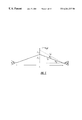
- FIG. 1 is a schematic of a tented film (foot and housing not shown).
- FIG. 2 is a section of a single sensor which may be in a link comprising a plurality of sensors.
- Links typically comprise three sensors.
- the housing, the upper and lower components of the film support structure within the housing, an arch in the lower film support component to accommodate a tented film, rails at the outer bottom edges of the housing and details illustrating the clamping of the film by the support structure are shown.
- FIG. 3 is an assembly drawing. On the left, the film (with attached foot) and the two piece film support structure are shown disassembled. On the right the same components are shown assembled.
- FIG. 4 depicts one side of a piezoelectric film strip. Nine conductive sensing areas, and details of the conductive ink printing on the film are shown. Because the film is transparent, some printing on the opposite side is illustrated as well.
- FIG. 5 is a top view of a single linear array or snake comprising three links, each comprising three sensors (nine sensors).
- Each of the three links may comprise one of the sensing areas of a film strip as shown by FIG. 4.
- a tape is shown adjacent each side of the three link array to eliminate undesirable sensor housing motion that may lead to mechanical cross-talk and to accommodate appropriate PVDF film tenting on a curved chest.
- Linear arrays comprising any desired number of links and sensors may be assembled in like manner.
- FIG. 6 illustrates a three dimensional view without the tape of a linear three link (nine sensor) array as shown by FIG. 5 .
- FIG. 7 is a bottom view of the snake of FIGS. 5 and 6 showing circular feet attached to the film with plastic bars (hashed lines) rectangular in cross-section.
- the feet may be other than circular, e.g., polygonal and the attachment means may be other than bars, e.g., discs.
- FIG. 8 is a side view of the three link (nine sensor) snake shown by FIGS. 5 and 6.
- FIG. 9 is a three dimensional view of the underside of a three link (nine sensor) snake as shown by FIGS. 5 and 6.
- FIG. 10 illustrates five, three link snakes positioned one within each of the five intercostal spaces (ICS's) of a patient.
- the snakes are positioned to accommodate a patient acoustic window.
- FIGS. 1 to 3 One preferred embodiment of the sensor is shown by FIGS. 1 to 3 .
- the film is slightly longer than the distance between the points at which the film is fixed to the housing, so that the film is initially slack.
- the film is tented by the weight of the housing.
- the sensitivity and frequency response of the sensor are dependent upon the housing mass, the surface area of the bottom of the foot, and the degree to which the film is tented (i.e., the “offset angle” ⁇ ).
- d 31 and ⁇ are the appropriate piezoelectric stress constant and dielectric permittivity of the film, respectively, and t is the film thickness.
- Equation 3 Y is Young's modulus for the piezoelectric polymer, and A is the cross-sectional area through the width of the film. It should be noted that for practical housing mass the dominant component of X is the initial static displacement due to the slack in the film.
- K med 6 ⁇ ⁇ ⁇ ⁇ a ⁇ ( ⁇ 1 - a ⁇ ⁇ ⁇ ⁇ ⁇ G ′ ⁇ ⁇ / 2 ) , ( 4 )
- the housing mass has a significant effect on the performance of the sensor.
- the resonance frequency, f n of the filter is a function of the housing mass, m h , the number of sensors in a single link, n s , and the equivalent stiffness, K eq (the series combination of K eff and K med for a single sensor).
- Equation 5 the mass of the sensor foot and the entrained mass of the acoustic medium trapped beneath the foot are neglected since they are each much smaller than the housing mass.
- the broadband sensitivity of the device increases with increasing housing mass, but practical considerations impose an upper limit on this parameter. These considerations include limits on patient tolerance of mass on his or her cheat and the threat of severely degrading sensor performance by having the housing rails come in contact with the patient's skin.
- FIGS. 2 and 3 illustrate the design of a single, slack film, sensor having an initial static displacement angle ⁇ 1 of about 9°, a single sensor (link) housing mass of about 42 grams, and a spring constant of about 3 kN/m.
- FIG. 2 shows a section of a single link 100 within a preferably metal housing 101 for a link of three sensors.
- the link housing comprises integral top and bottom parts 102 , 103 .
- the perimeter of housing part 102 is defined by a generally trapezoidal end wall 104 , by sidewalls 105 , 106 , top 107 and bottom 108 . Because the area of the top 107 is smaller than the area of the bottom 108 , the end and sidewalls 104 , 105 and 106 slope inwardly to render the top part 102 of the link housing trapezoidal in cross-section and so impart flexibility to a linear sensor array (see FIGS. 5 and 6 ).
- the bottom housing part 103 defines a chamber in which top and bottom film support components 109 and 110 are positioned. The outer bottom edges of the bottom housing part 103 provide sensor side rails 111 and 112 .
- a film 200 is shown pinched at the spaced apart points A, A′ between the top and bottom film support components 109 , 110 .
- the film segment which spans the space between the pinch points is slack.
- An arch 113 in the lower film support element 110 accommodates tenting of the slack film 200 .
- the sensitivity of the sensors may increase as a function of the housing mass (film mass loading).
- the mass of a single housing is from about 40 grams to about 45 grams.
- the housing mass may be less, e.g., 20 grams, or greater, e.g., 200 grams.
- Means 114 attach circular foot 115 to the exposed lower surface of the film 200 .
- the circular foot has a diameter of 0.2 to 0.5 inch, preferably 0.3 to 0.4 inch.
- a polygonal foot of like area may be used instead of a circular foot.
- This foot and the support bars may be fabricated from any desired plastic, e.g., polystyrene, polypropylene, polycarbonate or the like.
- the length of foot attachment means 114 is dimensioned to avoid patient skin contact of the sensor rails 111 , 112 provided by the bottom part 103 of the housing as shown in FIG. 2 .
- a through hole 115 for a set screw to maintain the housing 101 and film support parts 109 , 110 in assembly is shown (hashed lines).
- FIG. 3 shows a sensor disassembled (left portion).
- Upper and lower film support parts 109 and 110 are shown with pins 116 and pin receiving holes 116 a (hatched lines).
- the upper film support component is held in contact with the bottom component by friction between the pins 116 .
- FIG. 4 shows one side of a film 200 having nine rectangular spaced apart conductive sensing areas 1000 and associated printed conductive ink lines 1001 which connect the sensing areas to pins within a male component 1002 of a plastic connector.
- the sensing areas 1000 are equally spaced apart and separated by holes 1003 in the film 200 .
- Stiffeners 1004 have holes 1005 for assembly pins (not shown).
- Connector 1002 houses conducting pins 1006 .
- Polarity ridges 1007 are provided on the connector 1002 to facilitate proper orientation between the male 1002 and female (not shown) components of the connector.
- the invention includes a linear array of sensors positioned on a continuous piezoelectric film strip having a plurality of separate sensing elements spaced longitudinally apart on a surface thereof.
- a plurality of similarly longitudinally spaced sensors is positioned along the strip, wherein each of said sensors comprises at least one of the plurality of sensing elements on the surface of film strip.
- FIGS. 5 to 8 illustrate one embodiment of such a three-link (nine sensor) linear array 300 of links 301 .
- Each link comprises three sensors 100 (not shown).
- each link 301 has two holes 117 and 118 for set screws or like means to secure the link housing 101 to the film support components 109 , 110 (see FIG. 2 ).
- a rectangular reflective tape piece 119 is affixed to the top of each sensor 100 to accommodate photogrammetric sensor location procedures.
- Means for securing the three link linear sensor array against unwanted movement may be provided by adhesive tape 120 positioned at each side of the array.
- the portions of the film strip between each of the links included in the link 301 functions as a hinge to impart array flexibility to the array 300 .
- Housings are preferably metal. Zinc castings are appropriate to provide weight and shielding from electromagnetic interference.
- individual links 300 are appropriately spaced apart (center to center).
- Each flexible linear array is preferably capable of at least 10 degrees torsional rotation link-to-link from flat (by weight of the sensors alone) and a vertical hinge angle of at least +45 degrees and ⁇ 30 degrees relative to the adjacent link.
- the spacing between each of the linear arrays included in a group or assembly of linear arrays may be as little as 2 cm or as wide as 4 cm (center-to-center).
- the back of each linear array is preferably flat to accommodate visual imaging. Links and sensor elements preferably do not rub or clang on each other in order that mechanical cross-talk is reduced.
- Sensors included in an assembly or array preferably have interchannel phase differences of less than 1 degree standard deviation over the 100 Hz to 2 kHz frequency band when applied over the angles given.
- the sensor housing is preferably metal, e.g. zinc castings to provide weight and stability.
- Sensor temperatures during data acquisition may lie between 20° C. and 38° C.
- Sensor-to-sensor variations may be as high as 10° C.
- External temperature differences and dynamics between array elements preferably do not affect interchannel phase specifications within the performance band between 100 Hz and 2 kHz.
- the amplifier impedance to which each sensor may be attached (excluding cabling) is typically at 199 megohms in parallel with 25 pf or more.
- Cross-talk between any two sensors, other than through the intended propagation path is preferably less than ⁇ 30 dB.
- Connector/cable design is selected to minimize external noise propagation down the cable into the sensors, and preferably adapt to the array layout on human contours so that array performance is not compromised.
Landscapes
- Acoustics & Sound (AREA)
- Physics & Mathematics (AREA)
- Life Sciences & Earth Sciences (AREA)
- Engineering & Computer Science (AREA)
- Health & Medical Sciences (AREA)
- Surgery (AREA)
- General Health & Medical Sciences (AREA)
- Heart & Thoracic Surgery (AREA)
- Medical Informatics (AREA)
- Molecular Biology (AREA)
- Signal Processing (AREA)
- Animal Behavior & Ethology (AREA)
- Biomedical Technology (AREA)
- Public Health (AREA)
- Veterinary Medicine (AREA)
- Measurement Of The Respiration, Hearing Ability, Form, And Blood Characteristics Of Living Organisms (AREA)
- Investigating Or Analyzing Materials By The Use Of Ultrasonic Waves (AREA)
- Measurement Of Length, Angles, Or The Like Using Electric Or Magnetic Means (AREA)
- Push-Button Switches (AREA)
- Measuring Pulse, Heart Rate, Blood Pressure Or Blood Flow (AREA)
Abstract
Description


Claims (33)
Priority Applications (6)
| Application Number | Priority Date | Filing Date | Title |
|---|---|---|---|
| US09/136,933 US6261237B1 (en) | 1998-08-20 | 1998-08-20 | Thin film piezoelectric polymer sensor |
| EP99941125A EP1107696B1 (en) | 1998-08-20 | 1999-08-13 | Thin film piezoelectric polymer sensor |
| PCT/US1999/018459 WO2000010462A1 (en) | 1998-08-20 | 1999-08-13 | Thin film piezoelectric polymer sensor |
| AT99941125T ATE320757T1 (en) | 1998-08-20 | 1999-08-13 | SENSOR WITH A THIN PIEZOELECTRIC POLYMER LAYER |
| DE69930523T DE69930523T2 (en) | 1998-08-20 | 1999-08-13 | SENSOR WITH A THIN PIEZOELECTRIC POLYMER LAYER |
| AU54840/99A AU5484099A (en) | 1998-08-20 | 1999-08-13 | Thin film piezoelectric polymer sensor |
Applications Claiming Priority (1)
| Application Number | Priority Date | Filing Date | Title |
|---|---|---|---|
| US09/136,933 US6261237B1 (en) | 1998-08-20 | 1998-08-20 | Thin film piezoelectric polymer sensor |
Publications (1)
| Publication Number | Publication Date |
|---|---|
| US6261237B1 true US6261237B1 (en) | 2001-07-17 |
Family
ID=22475075
Family Applications (1)
| Application Number | Title | Priority Date | Filing Date |
|---|---|---|---|
| US09/136,933 Expired - Fee Related US6261237B1 (en) | 1998-08-20 | 1998-08-20 | Thin film piezoelectric polymer sensor |
Country Status (6)
| Country | Link |
|---|---|
| US (1) | US6261237B1 (en) |
| EP (1) | EP1107696B1 (en) |
| AT (1) | ATE320757T1 (en) |
| AU (1) | AU5484099A (en) |
| DE (1) | DE69930523T2 (en) |
| WO (1) | WO2000010462A1 (en) |
Cited By (42)
| Publication number | Priority date | Publication date | Assignee | Title |
|---|---|---|---|---|
| US6415033B1 (en) | 1999-09-15 | 2002-07-02 | Ilife Systems, Inc. | Physiological condition monitors utilizing very low frequency acoustic signals |
| US6416483B1 (en) | 2000-03-24 | 2002-07-09 | Ilife Systems, Inc. | Sensor and method for detecting very low frequency acoustic signals |
| US20030092977A1 (en) * | 2001-10-12 | 2003-05-15 | Sahatjian Ronald A. | Catheter Lesion diagnostics |
| US6575916B2 (en) | 2000-03-24 | 2003-06-10 | Ilife Solutions, Inc. | Apparatus and method for detecting very low frequency acoustic signals |
| WO2003082111A1 (en) * | 2002-03-25 | 2003-10-09 | Hoana Medical, Inc. | Passive physiological monitoring (p2m) system |
| US6699201B2 (en) | 1998-11-09 | 2004-03-02 | Medacoustics, Inc. | Acoustic window identification |
| US6706002B1 (en) * | 2000-03-24 | 2004-03-16 | Ilife Systems, Inc. | System and method for remotely monitoring at least one physiological characteristic of a child |
| US6716169B2 (en) * | 2000-08-24 | 2004-04-06 | Seiko Instruments Inc. | Ultrasonic sensor, method of fabricating same, and ultrasonic diagnostic device using an ultrasonic sensor |
| US20050190062A1 (en) * | 2003-12-04 | 2005-09-01 | Sullivan Patrick K. | Intelligent medical vigilance system |
| US20050190068A1 (en) * | 2004-02-18 | 2005-09-01 | Gentry Jason M. | Method and system for integrating a passive sensor array with a mattress for patient monitoring |
| US20050251047A1 (en) * | 1999-03-01 | 2005-11-10 | Medacoustics, Inc. | Low profile acoustic sensor array and sensors with pleated transmission lines and related methods |
| US6984207B1 (en) | 1999-09-14 | 2006-01-10 | Hoana Medical, Inc. | Passive physiological monitoring (P2M) system |
| US7037268B1 (en) | 1999-03-01 | 2006-05-02 | Medacoustics, Inc. | Low profile acoustic sensor arry and sensors with pleated transmission lines and related methods |
| US20060147730A1 (en) * | 2004-09-24 | 2006-07-06 | Rohm And Haas Electronic Materials Llc | Adhesion promoter for ferroelectric polymer films |
| US20060211951A1 (en) * | 2002-05-29 | 2006-09-21 | Zoran Milijasevic | Implantable bladder sensor |
| US20070113654A1 (en) * | 2005-11-23 | 2007-05-24 | Carim Hatim M | Weighted bioacoustic sensor and method of using same |
| US20070113649A1 (en) * | 2005-11-23 | 2007-05-24 | Vivek Bharti | Cantilevered bioacoustic sensor and method using same |
| US20070265535A1 (en) * | 2003-06-26 | 2007-11-15 | Sullivan Patrick K | Radiation Stress Non-Invasive Blood Pressure Method |
| US7666151B2 (en) | 2002-11-20 | 2010-02-23 | Hoana Medical, Inc. | Devices and methods for passive patient monitoring |
| US20100274099A1 (en) * | 2008-12-30 | 2010-10-28 | Masimo Corporation | Acoustic sensor assembly |
| US20110137210A1 (en) * | 2009-12-08 | 2011-06-09 | Johnson Marie A | Systems and methods for detecting cardiovascular disease |
| US8690799B2 (en) | 2009-10-15 | 2014-04-08 | Masimo Corporation | Acoustic respiratory monitoring sensor having multiple sensing elements |
| US9101274B2 (en) | 2010-06-24 | 2015-08-11 | Cvr Global, Inc. | Sensor, sensor pad and sensor array for detecting infrasonic acoustic signals |
| US9192351B1 (en) | 2011-07-22 | 2015-11-24 | Masimo Corporation | Acoustic respiratory monitoring sensor with probe-off detection |
| US9226726B1 (en) | 2014-11-25 | 2016-01-05 | John L Semmlow | Method and system for detection of cardiac sounds |
| US9370335B2 (en) | 2009-10-15 | 2016-06-21 | Masimo Corporation | Physiological acoustic monitoring system |
| US9386961B2 (en) | 2009-10-15 | 2016-07-12 | Masimo Corporation | Physiological acoustic monitoring system |
| US9767667B2 (en) | 2003-12-04 | 2017-09-19 | Hoana Medical, Inc. | Systems and methods for monitoring physiology with unable-to-measure alerts |
| US9782110B2 (en) | 2010-06-02 | 2017-10-10 | Masimo Corporation | Opticoustic sensor |
| US9955937B2 (en) | 2012-09-20 | 2018-05-01 | Masimo Corporation | Acoustic patient sensor coupler |
| US10039520B2 (en) | 2005-04-13 | 2018-08-07 | Aum Cardiovascular, Inc | Detection of coronary artery disease using an electronic stethoscope |
| US10357209B2 (en) | 2009-10-15 | 2019-07-23 | Masimo Corporation | Bidirectional physiological information display |
| US20190231311A1 (en) * | 2018-01-31 | 2019-08-01 | Samsung Medison Co., Ltd. | Ultrasound probe |
| US10412512B2 (en) | 2006-05-30 | 2019-09-10 | Soundmed, Llc | Methods and apparatus for processing audio signals |
| US10463340B2 (en) | 2009-10-15 | 2019-11-05 | Masimo Corporation | Acoustic respiratory monitoring systems and methods |
| US10484805B2 (en) | 2009-10-02 | 2019-11-19 | Soundmed, Llc | Intraoral appliance for sound transmission via bone conduction |
| US10828007B1 (en) | 2013-10-11 | 2020-11-10 | Masimo Corporation | Acoustic sensor with attachment portion |
| US10925573B2 (en) | 2017-10-04 | 2021-02-23 | Ausculsciences, Inc. | Auscultatory sound-or-vibration sensor |
| KR20220001975A (en) * | 2020-06-30 | 2022-01-06 | 한국과학기술원 | Voice sensor using thin film polymer |
| KR20220001973A (en) * | 2020-06-30 | 2022-01-06 | 한국과학기술원 | Voice sensor with different thickness and voice sensing method using same |
| US11413653B2 (en) | 2010-06-24 | 2022-08-16 | Cvr Global, Inc. | Sensor, sensor pad and sensor array for detecting infrasonic acoustic signals |
| US12616446B2 (en) | 2023-06-08 | 2026-05-05 | Ikko Health Ltd. | Wearable garment adapted for ultrasound sensing and methods thereto for full wave inversion with imprecise sensor positions |
Families Citing this family (12)
| Publication number | Priority date | Publication date | Assignee | Title |
|---|---|---|---|---|
| WO2001078059A2 (en) * | 2000-04-12 | 2001-10-18 | Andromed Inc. | Piezoelectric biological sounds monitor |
| US6661161B1 (en) | 2002-06-27 | 2003-12-09 | Andromed Inc. | Piezoelectric biological sound monitor with printed circuit board |
| EP2312995B1 (en) | 2008-05-05 | 2017-06-28 | Masimo Corporation | Pulse oximetry system with electrical decoupling circuitry |
| WO2011047211A1 (en) | 2009-10-15 | 2011-04-21 | Masimo Corporation | Pulse oximetry system with low noise cable hub |
| US9066680B1 (en) | 2009-10-15 | 2015-06-30 | Masimo Corporation | System for determining confidence in respiratory rate measurements |
| US9724016B1 (en) | 2009-10-16 | 2017-08-08 | Masimo Corp. | Respiration processor |
| GB2487882B (en) | 2009-12-04 | 2017-03-29 | Masimo Corp | Calibration for multi-stage physiological monitors |
| US9307928B1 (en) | 2010-03-30 | 2016-04-12 | Masimo Corporation | Plethysmographic respiration processor |
| EP2787747B1 (en) * | 2011-11-29 | 2017-06-28 | Sumitomo Riko Company Limited | Polymer speaker |
| US10441181B1 (en) | 2013-03-13 | 2019-10-15 | Masimo Corporation | Acoustic pulse and respiration monitoring system |
| KR101809714B1 (en) | 2017-04-25 | 2017-12-15 | 한국세라믹기술원 | Piezoelectric transducer including the piezoelectric unit and directive speaker including the transducer |
| CN111264066B (en) * | 2018-09-04 | 2022-03-01 | 凯色盖迈桑德仁·苏力娅固马尔 | Acoustic transducers and related fabrication and packaging techniques |
Citations (103)
| Publication number | Priority date | Publication date | Assignee | Title |
|---|---|---|---|---|
| US32180A (en) | 1861-04-30 | Halter-king | ||
| US3442264A (en) | 1964-06-04 | 1969-05-06 | Joseph R Levitt | Data processing method and means |
| US3573394A (en) * | 1967-09-14 | 1971-04-06 | Ind Scient Research Corp | Piezoelectric microphone with biasing means |
| US3799147A (en) | 1972-03-23 | 1974-03-26 | Directors University Cincinnat | Method and apparatus for diagnosing myocardial infarction in human heart |
| US3903733A (en) | 1972-11-20 | 1975-09-09 | Kureha Chemical Ind Co Ltd | Method of measuring vibrations by means of piezoelectric body and the apparatus therefor |
| US4008408A (en) | 1974-02-28 | 1977-02-15 | Pioneer Electronic Corporation | Piezoelectric electro-acoustic transducer |
| US4054808A (en) | 1974-08-19 | 1977-10-18 | Matsushita Electric Industrial Co., Ltd. | Vibration detecting device having a piezoelectric ceramic plate and a method for adapting the same for use in musical instruments |
| US4094308A (en) | 1976-08-19 | 1978-06-13 | Cormier Cardiac Systems, Inc. | Method and system for rapid non-invasive determination of the systolic time intervals |
| DE2703781A1 (en) | 1977-01-29 | 1978-08-03 | Bosch Gmbh Robert | Electronic stethoscope transducer - has rigid actuator to transmit body vibrations to circular piezoelectric element |
| US4146955A (en) | 1977-08-15 | 1979-04-03 | Harris Corporation | Method of fabricating a stepped-array acousto-optic beam deflector |
| US4226248A (en) | 1978-10-26 | 1980-10-07 | Manoli Samir H | Phonocephalographic device |
| US4234813A (en) | 1978-04-10 | 1980-11-18 | Toray Industries, Inc. | Piezoelectric or pyroelectric polymer input element for use as a transducer in keyboards |
| US4255791A (en) | 1978-12-04 | 1981-03-10 | Harris Corporation | Signal processing system |
| US4268912A (en) | 1978-06-06 | 1981-05-19 | Magnavox Government And Industrial Electronics Co. | Directional hydrophone suitable for flush mounting |
| US4308870A (en) | 1980-06-04 | 1982-01-05 | The Kendall Company | Vital signs monitor |
| US4376302A (en) | 1978-04-13 | 1983-03-08 | The United States Of America As Represented By The Secretary Of The Navy | Piezoelectric polymer hydrophone |
| US4385255A (en) | 1979-11-02 | 1983-05-24 | Yokogawa Electric Works, Ltd. | Linear array ultrasonic transducer |
| US4387378A (en) | 1978-06-28 | 1983-06-07 | Harris Corporation | Antenna having electrically positionable phase center |
| US4406967A (en) | 1980-08-23 | 1983-09-27 | Kureha Kagaku Kogyo Kabushiki Kaisha | Ultrasonic probe |
| US4413630A (en) | 1976-04-05 | 1983-11-08 | Diasonics Cardio/Imaging, Inc. | Sector scanner display and recording system for ultrasonic diagnosis |
| US4424465A (en) | 1979-05-16 | 1984-01-03 | Toray Industries, Inc. | Piezoelectric vibration transducer |
| US4428380A (en) | 1980-09-11 | 1984-01-31 | Hughes Aircraft Company | Method and improved apparatus for analyzing activity |
| DE3234584A1 (en) | 1982-09-17 | 1984-03-22 | Reinhard 8206 Bruckmühl Fuchs | Structure-borne sound pick-up of piezo-electric flexion pick-ups |
| US4458693A (en) | 1981-03-13 | 1984-07-10 | Medtronic, Inc. | Monitoring system |
| FR2507424B1 (en) | 1981-06-05 | 1984-09-14 | Cgr | |
| US4491051A (en) | 1980-02-22 | 1985-01-01 | Barcus Lester M | String instrument pickup system |
| US4509527A (en) | 1983-04-08 | 1985-04-09 | Timex Medical Products Corporation | Cardio-respiration transducer |
| US4546777A (en) | 1981-03-06 | 1985-10-15 | Siemens Gammasonics, Inc. | Heart sound detector and synchronization for diagnostics |
| US4549551A (en) | 1982-11-24 | 1985-10-29 | Her Majesty The Queen In Right Of Canada, As Represented By The Minister Of National Defense | Heart rate detector |
| DE3531399A1 (en) | 1984-09-03 | 1986-03-13 | Vickers PLC, London | BREATHING CONTROL DEVICE |
| US4586514A (en) | 1983-08-10 | 1986-05-06 | Biotronics Instruments | Phonoangiographic spectral analysing apparatus |
| EP0194823A2 (en) | 1985-03-12 | 1986-09-17 | BAXTER INTERNATIONAL INC. (a Delaware corporation) | Medical electrode |
| US4628321A (en) | 1982-04-14 | 1986-12-09 | Harris Corporation | Aperture transformation sidelobe canceller |
| US4630203A (en) | 1983-12-27 | 1986-12-16 | Thomas Szirtes | Contour radiography: a system for determining 3-dimensional contours of an object from its 2-dimensional images |
| US4656385A (en) | 1984-04-17 | 1987-04-07 | Murata Manufacturing Co., Ltd. | Housing having grooves therein for mounting a piezoelectric ladder filter |
| US4697597A (en) | 1982-02-12 | 1987-10-06 | Ernst Sanz | Apparatus for cardiogoniometry |
| US4700712A (en) | 1985-08-30 | 1987-10-20 | Willi Studer Ag | Method for determining the starting point and the end point of closed spatial signal patterns |
| US4712565A (en) | 1986-10-27 | 1987-12-15 | International Acoustics Incorporated | Method and apparatus for evaluating of artificial heart valves |
| US4742458A (en) | 1985-10-29 | 1988-05-03 | Software Plus, Inc. | Method and apparatus for performing pattern recognition analysis |
| US4777961A (en) | 1985-10-15 | 1988-10-18 | Bruce Saltzman | High sensitivity stethoscopic system and method |
| US4781200A (en) | 1985-10-04 | 1988-11-01 | Baker Donald A | Ambulatory non-invasive automatic fetal monitoring system |
| US4784154A (en) | 1986-11-13 | 1988-11-15 | Colin Electronics Co., Ltd. | Interference resistant biomedical transducer |
| US4792145A (en) | 1985-11-05 | 1988-12-20 | Sound Enhancement Systems, Inc. | Electronic stethoscope system and method |
| US4803986A (en) | 1987-04-24 | 1989-02-14 | Minnesota Mining And Manufacturing Company | Ergonometric transcutaneous electrical nerve stimulator |
| US4803996A (en) | 1987-09-28 | 1989-02-14 | Nippon Colin Co., Ltd. | Cardiovascular monitor |
| US4805633A (en) | 1987-01-26 | 1989-02-21 | Tdk Corporation | Displacement sensor |
| US4812976A (en) | 1983-07-22 | 1989-03-14 | Lundy Research Laboratories, Inc. | Method and apparatus for characterizing the unknown state of a physical system |
| US4821584A (en) | 1988-03-15 | 1989-04-18 | The United States Of America As Represented By The United States Department Of Energy | Piezoelectric film load cell robot collision detector |
| US4840183A (en) | 1987-08-13 | 1989-06-20 | Tdk Corporation | Electrocardiograph |
| US4842411A (en) | 1986-02-06 | 1989-06-27 | Vectron, Inc. | Method of automatically measuring the shape of a continuous surface |
| US4862144A (en) | 1987-04-21 | 1989-08-29 | Tao Billy S K | Movement monitor |
| US4862361A (en) | 1985-06-05 | 1989-08-29 | Massachusetts Institute Of Technology | Methods and apparatus for monitoring cardiovascular regulation using heart rate power spectral analysis |
| US4862897A (en) | 1985-11-05 | 1989-09-05 | Sound Enhancement Systems, Inc. | Electrocardiogram enhancement system and method |
| US4905706A (en) | 1988-04-20 | 1990-03-06 | Nippon Colin Co., Ltd. | Method an apparatus for detection of heart disease |
| GB2188732B (en) | 1986-04-07 | 1990-04-04 | Micro Medical Ltd | Portable computer apparatus for the display of a phonocardiogram and an electrocardiogram of a person |
| US4924875A (en) | 1987-10-09 | 1990-05-15 | Biometrak Corporation | Cardiac biopotential analysis system and method |
| US4928705A (en) | 1987-12-08 | 1990-05-29 | University Of Pittsburgh Of The Commonwealth System Of Higher Education | Acoustic aneurysm detector and associated method |
| US4947859A (en) | 1989-01-25 | 1990-08-14 | Cherne Medical, Inc. | Bio-acoustic signal sensing device |
| US4957369A (en) | 1989-01-23 | 1990-09-18 | California Institute Of Technology | Apparatus for measuring three-dimensional surface geometries |
| US4967760A (en) | 1989-02-02 | 1990-11-06 | Bennett Jr William R | Dynamic spectral phonocardiograph |
| US4991581A (en) | 1988-03-04 | 1991-02-12 | Andries Tek R&D Limited Partnership | Acoustic processing apparatus |
| US5002060A (en) | 1988-06-16 | 1991-03-26 | Dror Nedivi | Medical monitoring system |
| US5002058A (en) | 1986-04-25 | 1991-03-26 | Intra-Sonix, Inc. | Ultrasonic transducer |
| US5003605A (en) | 1989-08-14 | 1991-03-26 | Cardiodyne, Inc. | Electronically augmented stethoscope with timing sound |
| US5010889A (en) | 1988-02-04 | 1991-04-30 | Bloodline Technology | Intelligent stethoscope |
| US5012815A (en) | 1989-02-02 | 1991-05-07 | Yale University | Dynamic spectral phonocardiograph |
| US5025809A (en) | 1989-11-28 | 1991-06-25 | Cardionics, Inc. | Recording, digital stethoscope for identifying PCG signatures |
| US5035247A (en) | 1987-12-31 | 1991-07-30 | Jochen Heimann | Sensor for non-invasive measurement of sound, pressure and vibration on the human body |
| US5036857A (en) | 1989-10-26 | 1991-08-06 | Rutgers, The State University Of New Jersey | Noninvasive diagnostic system for coronary artery disease |
| US5056201A (en) | 1987-12-29 | 1991-10-15 | Seiko Instruments Inc. | Method of making a travelling-wave motor |
| US5086776A (en) | 1990-03-06 | 1992-02-11 | Precision Diagnostics, Inc. | Apparatus and method for sensing cardiac performance |
| US5109863A (en) | 1989-10-26 | 1992-05-05 | Rutgers, The State University Of New Jersey | Noninvasive diagnostic system for coronary artery disease |
| US5129403A (en) | 1988-04-14 | 1992-07-14 | The United States Of America As Represented By The Secretary Of The Navy | Method and apparatus for detecting and transducing intersaccular acoustic signals |
| US5140992A (en) | 1990-07-16 | 1992-08-25 | The United States Of America As Represented By The Administrator Of The National Aeronautics And Space Administration | Passive fetal monitoring sensor |
| US5164627A (en) | 1988-07-26 | 1992-11-17 | Harris Corporation | Phased array acoustic signal processor |
| US5176153A (en) | 1990-11-02 | 1993-01-05 | Eberhardt Allen C | Heart chamber simulator with electronic accelerated heart valve wear and fatigue test apparatus and method |
| US5213108A (en) | 1988-02-04 | 1993-05-25 | Blood Line Technology, Inc. | Visual display stethoscope |
| US5218969A (en) | 1988-02-04 | 1993-06-15 | Blood Line Technology, Inc. | Intelligent stethoscope |
| US5301679A (en) | 1991-05-31 | 1994-04-12 | Taylor Microtechnology, Inc. | Method and system for analysis of body sounds |
| US5315512A (en) | 1989-09-01 | 1994-05-24 | Montefiore Medical Center | Apparatus and method for generating image representations of a body utilizing an ultrasonic imaging subsystem and a three-dimensional digitizer subsystem |
| US5337752A (en) | 1992-05-21 | 1994-08-16 | Mcg International, Inc. | System for simultaneously producing and synchronizing spectral patterns of heart sounds and an ECG signal |
| US5363401A (en) | 1993-02-25 | 1994-11-08 | Harris Corporation | Mechanism for extracting hybrid (fh/ds) spread spectrum signals within multi-signal type environment |
| US5365937A (en) * | 1992-09-09 | 1994-11-22 | Mcg International, Inc. | Disposable sensing device with contaneous conformance |
| US5381804A (en) | 1992-10-15 | 1995-01-17 | Aspect Medical Systems, Inc. | Monitor and method for acquiring and processing electrical signals relating to bodily functions |
| US5406952A (en) * | 1993-02-11 | 1995-04-18 | Biosyss Corporation | Blood pressure monitoring system |
| US5455385A (en) | 1993-06-28 | 1995-10-03 | Harris Corporation | Multilayer LTCC tub architecture for hermetically sealing semiconductor die, external electrical access for which is provided by way of sidewall recesses |
| US5501229A (en) | 1994-08-01 | 1996-03-26 | New England Medical Center Hospital | Continuous monitoring using a predictive instrument |
| US5553113A (en) | 1994-11-18 | 1996-09-03 | Analogic Corporation | Auxiliary data acquisition in a medical imaging system |
| US5551437A (en) | 1992-12-05 | 1996-09-03 | Avl Medical Instruments Ag | Sensor for measuring blood pressure |
| US5595188A (en) | 1995-07-26 | 1997-01-21 | Flowscan, Inc. | Assembly process for polymer-based acoustic differential-output sensor |
| US5598845A (en) | 1995-11-16 | 1997-02-04 | Stellartech Research Corporation | Ultrasound transducer device for continuous imaging of the heart and other body parts |
| US5617869A (en) | 1995-06-16 | 1997-04-08 | The United States Of America As Represented By The Secretary Of The Navy | Device and method for locating flow blockage in a three-dimensional object |
| US5638823A (en) | 1995-08-28 | 1997-06-17 | Rutgers University | System and method for noninvasive detection of arterial stenosis |
| DE19649679A1 (en) | 1996-02-26 | 1997-08-28 | Samsung Electronics Co Ltd | Vibration detection sensor |
| US5673702A (en) | 1994-06-10 | 1997-10-07 | Cambridge Heart, Inc. | Method and apparatus for the improved electronic display of physiologic waveforms |
| US5680513A (en) | 1994-08-19 | 1997-10-21 | Hyland; David C. | Series parallel approach to identification of dynamic systems |
| US5686917A (en) | 1995-04-19 | 1997-11-11 | National Instruments Corporation | System and method for demultiplexing data in an instrumentation system |
| US5687738A (en) | 1995-07-03 | 1997-11-18 | The Regents Of The University Of Colorado | Apparatus and methods for analyzing heart sounds |
| US5704365A (en) | 1994-11-14 | 1998-01-06 | Cambridge Heart, Inc. | Using related signals to reduce ECG noise |
| US5724983A (en) | 1994-08-01 | 1998-03-10 | New England Center Hospitals, Inc. | Continuous monitoring using a predictive instrument |
| US5724967A (en) | 1995-11-21 | 1998-03-10 | Nellcor Puritan Bennett Incorporated | Noise reduction apparatus for low level analog signals |
| US5724968A (en) | 1993-12-29 | 1998-03-10 | First Opinion Corporation | Computerized medical diagnostic system including meta function |
| US5796920A (en) | 1994-08-19 | 1998-08-18 | Harris Corporation | Multiprocessor system and method for identification and adaptive control of dynamic systems |
Family Cites Families (2)
| Publication number | Priority date | Publication date | Assignee | Title |
|---|---|---|---|---|
| FR2581496B1 (en) * | 1985-05-02 | 1987-06-26 | Silec Liaisons Elec | MICROPHONE CONTACT SENSOR WITH PIEZO POLYMER MEMBRANE |
| JP2719038B2 (en) * | 1990-09-14 | 1998-02-25 | 宇部興産株式会社 | Bioacoustic transducer |
-
1998
- 1998-08-20 US US09/136,933 patent/US6261237B1/en not_active Expired - Fee Related
-
1999
- 1999-08-13 WO PCT/US1999/018459 patent/WO2000010462A1/en not_active Ceased
- 1999-08-13 AU AU54840/99A patent/AU5484099A/en not_active Abandoned
- 1999-08-13 EP EP99941125A patent/EP1107696B1/en not_active Expired - Lifetime
- 1999-08-13 AT AT99941125T patent/ATE320757T1/en not_active IP Right Cessation
- 1999-08-13 DE DE69930523T patent/DE69930523T2/en not_active Expired - Lifetime
Patent Citations (106)
| Publication number | Priority date | Publication date | Assignee | Title |
|---|---|---|---|---|
| US32180A (en) | 1861-04-30 | Halter-king | ||
| US3442264A (en) | 1964-06-04 | 1969-05-06 | Joseph R Levitt | Data processing method and means |
| US3573394A (en) * | 1967-09-14 | 1971-04-06 | Ind Scient Research Corp | Piezoelectric microphone with biasing means |
| US3799147A (en) | 1972-03-23 | 1974-03-26 | Directors University Cincinnat | Method and apparatus for diagnosing myocardial infarction in human heart |
| US3903733A (en) | 1972-11-20 | 1975-09-09 | Kureha Chemical Ind Co Ltd | Method of measuring vibrations by means of piezoelectric body and the apparatus therefor |
| US4008408A (en) | 1974-02-28 | 1977-02-15 | Pioneer Electronic Corporation | Piezoelectric electro-acoustic transducer |
| US4054808A (en) | 1974-08-19 | 1977-10-18 | Matsushita Electric Industrial Co., Ltd. | Vibration detecting device having a piezoelectric ceramic plate and a method for adapting the same for use in musical instruments |
| US4413630A (en) | 1976-04-05 | 1983-11-08 | Diasonics Cardio/Imaging, Inc. | Sector scanner display and recording system for ultrasonic diagnosis |
| US4413630B1 (en) | 1976-04-05 | 1994-04-05 | Diasonics Delaware Inc | Sector scanner display and recording system for ultrasonic diagnosis |
| US4094308A (en) | 1976-08-19 | 1978-06-13 | Cormier Cardiac Systems, Inc. | Method and system for rapid non-invasive determination of the systolic time intervals |
| DE2703781A1 (en) | 1977-01-29 | 1978-08-03 | Bosch Gmbh Robert | Electronic stethoscope transducer - has rigid actuator to transmit body vibrations to circular piezoelectric element |
| US4146955A (en) | 1977-08-15 | 1979-04-03 | Harris Corporation | Method of fabricating a stepped-array acousto-optic beam deflector |
| US4234813A (en) | 1978-04-10 | 1980-11-18 | Toray Industries, Inc. | Piezoelectric or pyroelectric polymer input element for use as a transducer in keyboards |
| US4376302A (en) | 1978-04-13 | 1983-03-08 | The United States Of America As Represented By The Secretary Of The Navy | Piezoelectric polymer hydrophone |
| US4268912A (en) | 1978-06-06 | 1981-05-19 | Magnavox Government And Industrial Electronics Co. | Directional hydrophone suitable for flush mounting |
| US4387378A (en) | 1978-06-28 | 1983-06-07 | Harris Corporation | Antenna having electrically positionable phase center |
| US4226248A (en) | 1978-10-26 | 1980-10-07 | Manoli Samir H | Phonocephalographic device |
| US4255791A (en) | 1978-12-04 | 1981-03-10 | Harris Corporation | Signal processing system |
| US4424465A (en) | 1979-05-16 | 1984-01-03 | Toray Industries, Inc. | Piezoelectric vibration transducer |
| US4385255A (en) | 1979-11-02 | 1983-05-24 | Yokogawa Electric Works, Ltd. | Linear array ultrasonic transducer |
| US4491051A (en) | 1980-02-22 | 1985-01-01 | Barcus Lester M | String instrument pickup system |
| US4308870A (en) | 1980-06-04 | 1982-01-05 | The Kendall Company | Vital signs monitor |
| US4406967A (en) | 1980-08-23 | 1983-09-27 | Kureha Kagaku Kogyo Kabushiki Kaisha | Ultrasonic probe |
| US4428380A (en) | 1980-09-11 | 1984-01-31 | Hughes Aircraft Company | Method and improved apparatus for analyzing activity |
| US4546777A (en) | 1981-03-06 | 1985-10-15 | Siemens Gammasonics, Inc. | Heart sound detector and synchronization for diagnostics |
| US4458693A (en) | 1981-03-13 | 1984-07-10 | Medtronic, Inc. | Monitoring system |
| FR2507424B1 (en) | 1981-06-05 | 1984-09-14 | Cgr | |
| US4697597A (en) | 1982-02-12 | 1987-10-06 | Ernst Sanz | Apparatus for cardiogoniometry |
| US4628321A (en) | 1982-04-14 | 1986-12-09 | Harris Corporation | Aperture transformation sidelobe canceller |
| DE3234584A1 (en) | 1982-09-17 | 1984-03-22 | Reinhard 8206 Bruckmühl Fuchs | Structure-borne sound pick-up of piezo-electric flexion pick-ups |
| US4549551A (en) | 1982-11-24 | 1985-10-29 | Her Majesty The Queen In Right Of Canada, As Represented By The Minister Of National Defense | Heart rate detector |
| US4509527A (en) | 1983-04-08 | 1985-04-09 | Timex Medical Products Corporation | Cardio-respiration transducer |
| US4812976A (en) | 1983-07-22 | 1989-03-14 | Lundy Research Laboratories, Inc. | Method and apparatus for characterizing the unknown state of a physical system |
| US4586514A (en) | 1983-08-10 | 1986-05-06 | Biotronics Instruments | Phonoangiographic spectral analysing apparatus |
| US4630203A (en) | 1983-12-27 | 1986-12-16 | Thomas Szirtes | Contour radiography: a system for determining 3-dimensional contours of an object from its 2-dimensional images |
| US4656385A (en) | 1984-04-17 | 1987-04-07 | Murata Manufacturing Co., Ltd. | Housing having grooves therein for mounting a piezoelectric ladder filter |
| DE3531399A1 (en) | 1984-09-03 | 1986-03-13 | Vickers PLC, London | BREATHING CONTROL DEVICE |
| EP0194823A2 (en) | 1985-03-12 | 1986-09-17 | BAXTER INTERNATIONAL INC. (a Delaware corporation) | Medical electrode |
| US4862361A (en) | 1985-06-05 | 1989-08-29 | Massachusetts Institute Of Technology | Methods and apparatus for monitoring cardiovascular regulation using heart rate power spectral analysis |
| US4700712A (en) | 1985-08-30 | 1987-10-20 | Willi Studer Ag | Method for determining the starting point and the end point of closed spatial signal patterns |
| US4781200A (en) | 1985-10-04 | 1988-11-01 | Baker Donald A | Ambulatory non-invasive automatic fetal monitoring system |
| US4777961A (en) | 1985-10-15 | 1988-10-18 | Bruce Saltzman | High sensitivity stethoscopic system and method |
| US4742458A (en) | 1985-10-29 | 1988-05-03 | Software Plus, Inc. | Method and apparatus for performing pattern recognition analysis |
| US4862897A (en) | 1985-11-05 | 1989-09-05 | Sound Enhancement Systems, Inc. | Electrocardiogram enhancement system and method |
| US4792145A (en) | 1985-11-05 | 1988-12-20 | Sound Enhancement Systems, Inc. | Electronic stethoscope system and method |
| US4842411A (en) | 1986-02-06 | 1989-06-27 | Vectron, Inc. | Method of automatically measuring the shape of a continuous surface |
| GB2188732B (en) | 1986-04-07 | 1990-04-04 | Micro Medical Ltd | Portable computer apparatus for the display of a phonocardiogram and an electrocardiogram of a person |
| US5002058A (en) | 1986-04-25 | 1991-03-26 | Intra-Sonix, Inc. | Ultrasonic transducer |
| US4712565A (en) | 1986-10-27 | 1987-12-15 | International Acoustics Incorporated | Method and apparatus for evaluating of artificial heart valves |
| US4784154A (en) | 1986-11-13 | 1988-11-15 | Colin Electronics Co., Ltd. | Interference resistant biomedical transducer |
| US4805633A (en) | 1987-01-26 | 1989-02-21 | Tdk Corporation | Displacement sensor |
| US4862144A (en) | 1987-04-21 | 1989-08-29 | Tao Billy S K | Movement monitor |
| US4803986A (en) | 1987-04-24 | 1989-02-14 | Minnesota Mining And Manufacturing Company | Ergonometric transcutaneous electrical nerve stimulator |
| US4840183A (en) | 1987-08-13 | 1989-06-20 | Tdk Corporation | Electrocardiograph |
| US4803996A (en) | 1987-09-28 | 1989-02-14 | Nippon Colin Co., Ltd. | Cardiovascular monitor |
| US4924875A (en) | 1987-10-09 | 1990-05-15 | Biometrak Corporation | Cardiac biopotential analysis system and method |
| US4928705A (en) | 1987-12-08 | 1990-05-29 | University Of Pittsburgh Of The Commonwealth System Of Higher Education | Acoustic aneurysm detector and associated method |
| US5056201A (en) | 1987-12-29 | 1991-10-15 | Seiko Instruments Inc. | Method of making a travelling-wave motor |
| US5035247A (en) | 1987-12-31 | 1991-07-30 | Jochen Heimann | Sensor for non-invasive measurement of sound, pressure and vibration on the human body |
| US5213108A (en) | 1988-02-04 | 1993-05-25 | Blood Line Technology, Inc. | Visual display stethoscope |
| US5218969A (en) | 1988-02-04 | 1993-06-15 | Blood Line Technology, Inc. | Intelligent stethoscope |
| US5010889A (en) | 1988-02-04 | 1991-04-30 | Bloodline Technology | Intelligent stethoscope |
| US4991581A (en) | 1988-03-04 | 1991-02-12 | Andries Tek R&D Limited Partnership | Acoustic processing apparatus |
| US4821584A (en) | 1988-03-15 | 1989-04-18 | The United States Of America As Represented By The United States Department Of Energy | Piezoelectric film load cell robot collision detector |
| US5129403A (en) | 1988-04-14 | 1992-07-14 | The United States Of America As Represented By The Secretary Of The Navy | Method and apparatus for detecting and transducing intersaccular acoustic signals |
| US4905706A (en) | 1988-04-20 | 1990-03-06 | Nippon Colin Co., Ltd. | Method an apparatus for detection of heart disease |
| US5002060A (en) | 1988-06-16 | 1991-03-26 | Dror Nedivi | Medical monitoring system |
| US5164627A (en) | 1988-07-26 | 1992-11-17 | Harris Corporation | Phased array acoustic signal processor |
| US4957369A (en) | 1989-01-23 | 1990-09-18 | California Institute Of Technology | Apparatus for measuring three-dimensional surface geometries |
| US4947859A (en) | 1989-01-25 | 1990-08-14 | Cherne Medical, Inc. | Bio-acoustic signal sensing device |
| US4967760A (en) | 1989-02-02 | 1990-11-06 | Bennett Jr William R | Dynamic spectral phonocardiograph |
| US5012815A (en) | 1989-02-02 | 1991-05-07 | Yale University | Dynamic spectral phonocardiograph |
| US5003605A (en) | 1989-08-14 | 1991-03-26 | Cardiodyne, Inc. | Electronically augmented stethoscope with timing sound |
| US5315512A (en) | 1989-09-01 | 1994-05-24 | Montefiore Medical Center | Apparatus and method for generating image representations of a body utilizing an ultrasonic imaging subsystem and a three-dimensional digitizer subsystem |
| US5109863A (en) | 1989-10-26 | 1992-05-05 | Rutgers, The State University Of New Jersey | Noninvasive diagnostic system for coronary artery disease |
| US5036857A (en) | 1989-10-26 | 1991-08-06 | Rutgers, The State University Of New Jersey | Noninvasive diagnostic system for coronary artery disease |
| US5025809A (en) | 1989-11-28 | 1991-06-25 | Cardionics, Inc. | Recording, digital stethoscope for identifying PCG signatures |
| US5086776A (en) | 1990-03-06 | 1992-02-11 | Precision Diagnostics, Inc. | Apparatus and method for sensing cardiac performance |
| US5140992A (en) | 1990-07-16 | 1992-08-25 | The United States Of America As Represented By The Administrator Of The National Aeronautics And Space Administration | Passive fetal monitoring sensor |
| US5176153A (en) | 1990-11-02 | 1993-01-05 | Eberhardt Allen C | Heart chamber simulator with electronic accelerated heart valve wear and fatigue test apparatus and method |
| US5301679A (en) | 1991-05-31 | 1994-04-12 | Taylor Microtechnology, Inc. | Method and system for analysis of body sounds |
| US5337752A (en) | 1992-05-21 | 1994-08-16 | Mcg International, Inc. | System for simultaneously producing and synchronizing spectral patterns of heart sounds and an ECG signal |
| US5365937A (en) * | 1992-09-09 | 1994-11-22 | Mcg International, Inc. | Disposable sensing device with contaneous conformance |
| US5807268A (en) | 1992-09-09 | 1998-09-15 | Medacoustics, Inc. | Disposable sensing device with contaneous conformance |
| US5381804A (en) | 1992-10-15 | 1995-01-17 | Aspect Medical Systems, Inc. | Monitor and method for acquiring and processing electrical signals relating to bodily functions |
| US5551437A (en) | 1992-12-05 | 1996-09-03 | Avl Medical Instruments Ag | Sensor for measuring blood pressure |
| US5406952A (en) * | 1993-02-11 | 1995-04-18 | Biosyss Corporation | Blood pressure monitoring system |
| US5363401A (en) | 1993-02-25 | 1994-11-08 | Harris Corporation | Mechanism for extracting hybrid (fh/ds) spread spectrum signals within multi-signal type environment |
| US5455385A (en) | 1993-06-28 | 1995-10-03 | Harris Corporation | Multilayer LTCC tub architecture for hermetically sealing semiconductor die, external electrical access for which is provided by way of sidewall recesses |
| US5724968A (en) | 1993-12-29 | 1998-03-10 | First Opinion Corporation | Computerized medical diagnostic system including meta function |
| US5673702A (en) | 1994-06-10 | 1997-10-07 | Cambridge Heart, Inc. | Method and apparatus for the improved electronic display of physiologic waveforms |
| US5501229A (en) | 1994-08-01 | 1996-03-26 | New England Medical Center Hospital | Continuous monitoring using a predictive instrument |
| US5724983A (en) | 1994-08-01 | 1998-03-10 | New England Center Hospitals, Inc. | Continuous monitoring using a predictive instrument |
| US5718233A (en) | 1994-08-01 | 1998-02-17 | New England Medical Center Hospitals, Inc. | Continuous monitoring using a predictive instrument |
| US5796920A (en) | 1994-08-19 | 1998-08-18 | Harris Corporation | Multiprocessor system and method for identification and adaptive control of dynamic systems |
| US5680513A (en) | 1994-08-19 | 1997-10-21 | Hyland; David C. | Series parallel approach to identification of dynamic systems |
| US5704365A (en) | 1994-11-14 | 1998-01-06 | Cambridge Heart, Inc. | Using related signals to reduce ECG noise |
| US5553113A (en) | 1994-11-18 | 1996-09-03 | Analogic Corporation | Auxiliary data acquisition in a medical imaging system |
| US5686917A (en) | 1995-04-19 | 1997-11-11 | National Instruments Corporation | System and method for demultiplexing data in an instrumentation system |
| US5617869A (en) | 1995-06-16 | 1997-04-08 | The United States Of America As Represented By The Secretary Of The Navy | Device and method for locating flow blockage in a three-dimensional object |
| US5687738A (en) | 1995-07-03 | 1997-11-18 | The Regents Of The University Of Colorado | Apparatus and methods for analyzing heart sounds |
| US5595188A (en) | 1995-07-26 | 1997-01-21 | Flowscan, Inc. | Assembly process for polymer-based acoustic differential-output sensor |
| US5638823A (en) | 1995-08-28 | 1997-06-17 | Rutgers University | System and method for noninvasive detection of arterial stenosis |
| US5598845A (en) | 1995-11-16 | 1997-02-04 | Stellartech Research Corporation | Ultrasound transducer device for continuous imaging of the heart and other body parts |
| US5724967A (en) | 1995-11-21 | 1998-03-10 | Nellcor Puritan Bennett Incorporated | Noise reduction apparatus for low level analog signals |
| DE19649679A1 (en) | 1996-02-26 | 1997-08-28 | Samsung Electronics Co Ltd | Vibration detection sensor |
Non-Patent Citations (22)
| Title |
|---|
| Akay et al., "Application of Adaptive Filters to Noninvasive Acoustical Detection of Coronary Occlusions Before and After Angioplasty," IEEE Transactions on Biomedical Engineering, vol. 39, No. 2, pp. 176-183 (Feb. 1992). |
| Akay et al., "Application of Adaptive FTF/FAEST Zero Tracking Filters to Noninvasive Characterization of the Sound Pattern Caused by Coronary Artery Stenosis Before and After Angioplasty," Annals of Biomedical Engineering, vol. 21, pp. 9-17 (1993). |
| Akay et al., "Noninvasive acoustical detection of coronary artery disease using the adaptive line enhancer method," Medical & Biological Engineering & Computing, vol. 30, pp. 147-154 (Mar. 1992). |
| Akay et al.,"Noninvasive Acoustical Detection of Coronary Artery Disease: A Comparative Study of Signal Processing Methods," IEEE Transactions on Biomedical Engineering, vol. 40, No. 6, pp. 571-5784 (Jun. 1993). |
| Donnerstein, "Continuous Spectral Analysis of Heart Murmurs for Evaluating Stenotic Cardiac Lesions," The Am. Journ. Card., vol. 64, pp. 625-630 (Sep. 15, 1989). |
| Durand et al., "Evaluation of FFT-Based and Modern Parametric Methods for the Spectral Analysis of Bioprosthetic Valve Sounds," IEEE Trans. on Biomedical Eng., vol. BME-33, No. 6, pp. 572-578 (Jun. 1986). |
| Foale et al., "Detection of aortic porcine valve dysfunction by maximum entrophy spectral analysis," Circulation, vol. 68, No. 1, pp. 42-49 (Jul. 1983). |
| Fraden, "Application of Piezo/Pyroelectric Films in Medical Transducers," Jour. of Clinical Eng., vol. 13, No. 3, pp. 133-138 (Mar.-Apr. 1988). |
| Iwata et al., "Algorithm for Detecting the First and Second Heart Sounds by Spectral Tracking," Medical & Biological Engineering and Computing, pp. 19-26 (Jan. 1980). |
| Johnson et al., "Estimation of the Severity of Aortic Valve Stenosis by Frequency Analysis of the Murmur," J. Am. Coll. Cardiol., 1(5):1315-23 (1983). |
| Johnson et al., "Evaluation of Aortic Stenosis by Spectral Analysis of the Murmur," JACC, vol. 6, No. 1, pp. 55-65 (Jul. 1985). |
| Joo et al."Pole-Zero Modeling and Classification of Phonocardiograms," IEEE Trans. on Biomedical Eng., vol. BME-30, No. 2, pp. 110-118 (Feb. 1983). |
| Kagawa et al., "Real-time sound spectroanalysis for diagnosis of malfunctioning prosthetic valves," J. Thorac. Cardiovasc. Surg., vol. 79, pp. 671-679 (May 1980). |
| Lees et al., "Phonoangiography: A New Noninvasive Diagnostic Method for Studying Arterial Disease," Proceedings of the National Academy of Sciences, vol. 67, No. 2, pp. 935-942 (Oct. 1970). |
| PCT International Search Report, PCT International Application No. PCT/US99/18459, mailed Jan. 12, 1999). |
| Qian et al., "Orthogonal-Like Discrete Gabor Expansion," 26th Conf. on Infor. Sci an Systems, Princeton University (Mar. 18, 1992). |
| Semmlow et al., "Coronary Artery Disease-Correlates Between Diastolic Auditory Characteristics and Coronary Artery Stenoses," IEEE Transactions on Biomedical Engineering, vol. BME-30, No. 2, pp. 136-139 (Feb. 1983). |
| Semmlow et al., "Non-Invasive Diagnosis of Coronary Artery Disease by Enhanced Coronary Phonocardiography," IEEE Frontiers of Eng. in Health Care, pp. 181-185 (1982). |
| Semmlow et al., Noninvasive Detection of Coronary Artery Disease Using Parametric Spectral Analysis Methods, IEEE Engineering in Medicine and Biology Magazine, pp. 33-36 (Mar. 1990). |
| Stein et al., "Frequency Spectra of the First Heart Sound and of the Aortic Component of the Second Heart Sound in Patients with Degenerated Porcine Bioprosthetic Valves," The Am. Journ. of Carad., vol. 53, pp. 557-581 (Feb. 1, 1984). |
| von Gierke, H. et al., "Physics of Vibrations in Living Tissues," J. App. Physiology, vol. 4, pp. 886-900 (Jun. 1952). |
| Wang et al., Modeling Sound Generation in Stenosed Coronary Arteries, IEEE Transactions on Biomedical Engineering, vol. 37, No. 11, pp. 1087-1094 (Nov. 1990). |
Cited By (89)
| Publication number | Priority date | Publication date | Assignee | Title |
|---|---|---|---|---|
| US6699201B2 (en) | 1998-11-09 | 2004-03-02 | Medacoustics, Inc. | Acoustic window identification |
| US7037268B1 (en) | 1999-03-01 | 2006-05-02 | Medacoustics, Inc. | Low profile acoustic sensor arry and sensors with pleated transmission lines and related methods |
| US20050251047A1 (en) * | 1999-03-01 | 2005-11-10 | Medacoustics, Inc. | Low profile acoustic sensor array and sensors with pleated transmission lines and related methods |
| US6984207B1 (en) | 1999-09-14 | 2006-01-10 | Hoana Medical, Inc. | Passive physiological monitoring (P2M) system |
| US20060063982A1 (en) * | 1999-09-14 | 2006-03-23 | Hoana Medical, Inc. | Passive physiological monitoring (P2M) system |
| US6415033B1 (en) | 1999-09-15 | 2002-07-02 | Ilife Systems, Inc. | Physiological condition monitors utilizing very low frequency acoustic signals |
| US6947565B2 (en) | 1999-09-15 | 2005-09-20 | Ilife Solutions, Inc. | Physiological condition monitors utilizing very low frequency acoustic signals |
| US20030072458A1 (en) * | 1999-09-15 | 2003-04-17 | Ilife Solutions, Inc. | Physiological condition monitors utilizing very low frequency acoustic signals |
| US6575916B2 (en) | 2000-03-24 | 2003-06-10 | Ilife Solutions, Inc. | Apparatus and method for detecting very low frequency acoustic signals |
| US6706002B1 (en) * | 2000-03-24 | 2004-03-16 | Ilife Systems, Inc. | System and method for remotely monitoring at least one physiological characteristic of a child |
| WO2001072204A3 (en) * | 2000-03-24 | 2004-07-08 | Ilife Systems Inc | System and method for remotely monitoring at least one physiological characteristic of a child |
| US20050065457A1 (en) * | 2000-03-24 | 2005-03-24 | Caring Technologies, Inc. | System and method for remotely monitoring at least one physiological characteristic of a child |
| US6416483B1 (en) | 2000-03-24 | 2002-07-09 | Ilife Systems, Inc. | Sensor and method for detecting very low frequency acoustic signals |
| US6716169B2 (en) * | 2000-08-24 | 2004-04-06 | Seiko Instruments Inc. | Ultrasonic sensor, method of fabricating same, and ultrasonic diagnostic device using an ultrasonic sensor |
| US7291110B2 (en) | 2001-10-12 | 2007-11-06 | Boston Scientific Corporation | Catheter lesion diagnostics |
| US20030092977A1 (en) * | 2001-10-12 | 2003-05-15 | Sahatjian Ronald A. | Catheter Lesion diagnostics |
| CN100518638C (en) * | 2002-03-25 | 2009-07-29 | 赫艾纳医疗公司 | Passive physiological monitoring (P2M) system |
| WO2003082111A1 (en) * | 2002-03-25 | 2003-10-09 | Hoana Medical, Inc. | Passive physiological monitoring (p2m) system |
| US20060211951A1 (en) * | 2002-05-29 | 2006-09-21 | Zoran Milijasevic | Implantable bladder sensor |
| US7666151B2 (en) | 2002-11-20 | 2010-02-23 | Hoana Medical, Inc. | Devices and methods for passive patient monitoring |
| US20070265535A1 (en) * | 2003-06-26 | 2007-11-15 | Sullivan Patrick K | Radiation Stress Non-Invasive Blood Pressure Method |
| US7654962B2 (en) | 2003-06-26 | 2010-02-02 | Hoana Medical, Inc. | Radiation stress non-invasive blood pressure method |
| US9767667B2 (en) | 2003-12-04 | 2017-09-19 | Hoana Medical, Inc. | Systems and methods for monitoring physiology with unable-to-measure alerts |
| US7304580B2 (en) | 2003-12-04 | 2007-12-04 | Hoana Medical, Inc. | Intelligent medical vigilance system |
| US20050190062A1 (en) * | 2003-12-04 | 2005-09-01 | Sullivan Patrick K. | Intelligent medical vigilance system |
| US20050190068A1 (en) * | 2004-02-18 | 2005-09-01 | Gentry Jason M. | Method and system for integrating a passive sensor array with a mattress for patient monitoring |
| US7652581B2 (en) | 2004-02-18 | 2010-01-26 | Hoana Medical, Inc. | Method and system for integrating a passive sensor array with a mattress for patient monitoring |
| US20060147730A1 (en) * | 2004-09-24 | 2006-07-06 | Rohm And Haas Electronic Materials Llc | Adhesion promoter for ferroelectric polymer films |
| US10039520B2 (en) | 2005-04-13 | 2018-08-07 | Aum Cardiovascular, Inc | Detection of coronary artery disease using an electronic stethoscope |
| US20070113649A1 (en) * | 2005-11-23 | 2007-05-24 | Vivek Bharti | Cantilevered bioacoustic sensor and method using same |
| US20070113654A1 (en) * | 2005-11-23 | 2007-05-24 | Carim Hatim M | Weighted bioacoustic sensor and method of using same |
| US7998091B2 (en) | 2005-11-23 | 2011-08-16 | 3M Innovative Properties Company | Weighted bioacoustic sensor and method of using same |
| US8024974B2 (en) * | 2005-11-23 | 2011-09-27 | 3M Innovative Properties Company | Cantilevered bioacoustic sensor and method using same |
| US8333718B2 (en) | 2005-11-23 | 2012-12-18 | 3M Innovative Properties Company | Weighted bioacoustic sensor and method of using same |
| US10735874B2 (en) | 2006-05-30 | 2020-08-04 | Soundmed, Llc | Methods and apparatus for processing audio signals |
| US11178496B2 (en) | 2006-05-30 | 2021-11-16 | Soundmed, Llc | Methods and apparatus for transmitting vibrations |
| US10412512B2 (en) | 2006-05-30 | 2019-09-10 | Soundmed, Llc | Methods and apparatus for processing audio signals |
| US10477330B2 (en) | 2006-05-30 | 2019-11-12 | Soundmed, Llc | Methods and apparatus for transmitting vibrations |
| US10536789B2 (en) | 2006-05-30 | 2020-01-14 | Soundmed, Llc | Actuator systems for oral-based appliances |
| US9131917B2 (en) * | 2008-12-30 | 2015-09-15 | Masimo Corporation | Acoustic sensor assembly |
| US9028429B2 (en) * | 2008-12-30 | 2015-05-12 | Masimo Corporation | Acoustic sensor assembly |
| US20150196270A1 (en) * | 2008-12-30 | 2015-07-16 | Masimo Corporation | Acoustic sensor assembly |
| US20140309559A1 (en) * | 2008-12-30 | 2014-10-16 | Masimo Corporation | Acoustic sensor assembly |
| US9795358B2 (en) * | 2008-12-30 | 2017-10-24 | Masimo Corporation | Acoustic sensor assembly |
| US20100274099A1 (en) * | 2008-12-30 | 2010-10-28 | Masimo Corporation | Acoustic sensor assembly |
| US10548561B2 (en) * | 2008-12-30 | 2020-02-04 | Masimo Corporation | Acoustic sensor assembly |
| US8771204B2 (en) * | 2008-12-30 | 2014-07-08 | Masimo Corporation | Acoustic sensor assembly |
| US11559275B2 (en) * | 2008-12-30 | 2023-01-24 | Masimo Corporation | Acoustic sensor assembly |
| US12232905B2 (en) * | 2008-12-30 | 2025-02-25 | Masimo Corporation | Acoustic sensor assembly |
| US20180125445A1 (en) * | 2008-12-30 | 2018-05-10 | Masimo Corporation | Acoustic sensor assembly |
| US10484805B2 (en) | 2009-10-02 | 2019-11-19 | Soundmed, Llc | Intraoral appliance for sound transmission via bone conduction |
| US10463340B2 (en) | 2009-10-15 | 2019-11-05 | Masimo Corporation | Acoustic respiratory monitoring systems and methods |
| US8755535B2 (en) | 2009-10-15 | 2014-06-17 | Masimo Corporation | Acoustic respiratory monitoring sensor having multiple sensing elements |
| US9867578B2 (en) | 2009-10-15 | 2018-01-16 | Masimo Corporation | Physiological acoustic monitoring system |
| US12558033B2 (en) | 2009-10-15 | 2026-02-24 | Masimo Corporation | Acoustic respiratory monitoring sensor having multiple sensing elements |
| US8690799B2 (en) | 2009-10-15 | 2014-04-08 | Masimo Corporation | Acoustic respiratory monitoring sensor having multiple sensing elements |
| US12257081B2 (en) | 2009-10-15 | 2025-03-25 | Masimo Corporation | Bidirectional physiological information display |
| US10098610B2 (en) | 2009-10-15 | 2018-10-16 | Masimo Corporation | Physiological acoustic monitoring system |
| US10349895B2 (en) | 2009-10-15 | 2019-07-16 | Masimo Corporation | Acoustic respiratory monitoring sensor having multiple sensing elements |
| US10357209B2 (en) | 2009-10-15 | 2019-07-23 | Masimo Corporation | Bidirectional physiological information display |
| US8715206B2 (en) | 2009-10-15 | 2014-05-06 | Masimo Corporation | Acoustic patient sensor |
| US9538980B2 (en) | 2009-10-15 | 2017-01-10 | Masimo Corporation | Acoustic respiratory monitoring sensor having multiple sensing elements |
| US8702627B2 (en) | 2009-10-15 | 2014-04-22 | Masimo Corporation | Acoustic respiratory monitoring sensor having multiple sensing elements |
| US9386961B2 (en) | 2009-10-15 | 2016-07-12 | Masimo Corporation | Physiological acoustic monitoring system |
| US9370335B2 (en) | 2009-10-15 | 2016-06-21 | Masimo Corporation | Physiological acoustic monitoring system |
| US11998362B2 (en) | 2009-10-15 | 2024-06-04 | Masimo Corporation | Acoustic respiratory monitoring sensor having multiple sensing elements |
| US10925544B2 (en) | 2009-10-15 | 2021-02-23 | Masimo Corporation | Acoustic respiratory monitoring sensor having multiple sensing elements |
| US20110137210A1 (en) * | 2009-12-08 | 2011-06-09 | Johnson Marie A | Systems and methods for detecting cardiovascular disease |
| US9782110B2 (en) | 2010-06-02 | 2017-10-10 | Masimo Corporation | Opticoustic sensor |
| US11413653B2 (en) | 2010-06-24 | 2022-08-16 | Cvr Global, Inc. | Sensor, sensor pad and sensor array for detecting infrasonic acoustic signals |
| US9101274B2 (en) | 2010-06-24 | 2015-08-11 | Cvr Global, Inc. | Sensor, sensor pad and sensor array for detecting infrasonic acoustic signals |
| US9192351B1 (en) | 2011-07-22 | 2015-11-24 | Masimo Corporation | Acoustic respiratory monitoring sensor with probe-off detection |
| US11020084B2 (en) | 2012-09-20 | 2021-06-01 | Masimo Corporation | Acoustic patient sensor coupler |
| US9955937B2 (en) | 2012-09-20 | 2018-05-01 | Masimo Corporation | Acoustic patient sensor coupler |
| US11992361B2 (en) | 2012-09-20 | 2024-05-28 | Masimo Corporation | Acoustic patient sensor coupler |
| US10828007B1 (en) | 2013-10-11 | 2020-11-10 | Masimo Corporation | Acoustic sensor with attachment portion |
| US12016721B2 (en) | 2013-10-11 | 2024-06-25 | Masimo Corporation | Acoustic sensor with attachment portion |
| US9226726B1 (en) | 2014-11-25 | 2016-01-05 | John L Semmlow | Method and system for detection of cardiac sounds |
| US9320489B1 (en) | 2014-11-25 | 2016-04-26 | John Leonard Semmlow | Apparatus for detection of cardiac acoustic signals |
| US11510644B2 (en) | 2017-10-04 | 2022-11-29 | Ausculsciences, Inc. | Wiring harness for use with auscultatory sound-or-vibration sensors |
| US11896420B2 (en) | 2017-10-04 | 2024-02-13 | Ausculsciences, Inc. | Auscultatory sound-or-vibration sensor |
| US10925573B2 (en) | 2017-10-04 | 2021-02-23 | Ausculsciences, Inc. | Auscultatory sound-or-vibration sensor |
| US20190231311A1 (en) * | 2018-01-31 | 2019-08-01 | Samsung Medison Co., Ltd. | Ultrasound probe |
| US11185306B2 (en) * | 2018-01-31 | 2021-11-30 | Samsung Medison Co., Ltd. | Ultrasound probe |
| KR102505540B1 (en) | 2020-06-30 | 2023-03-06 | 한국과학기술원 | Voice sensor using thin film polymer |
| KR102400357B1 (en) | 2020-06-30 | 2022-05-23 | 한국과학기술원 | Voice sensor with different thickness and voice sensing method using same |
| KR20220001973A (en) * | 2020-06-30 | 2022-01-06 | 한국과학기술원 | Voice sensor with different thickness and voice sensing method using same |
| KR20220001975A (en) * | 2020-06-30 | 2022-01-06 | 한국과학기술원 | Voice sensor using thin film polymer |
| US12616446B2 (en) | 2023-06-08 | 2026-05-05 | Ikko Health Ltd. | Wearable garment adapted for ultrasound sensing and methods thereto for full wave inversion with imprecise sensor positions |
Also Published As
| Publication number | Publication date |
|---|---|
| WO2000010462A1 (en) | 2000-03-02 |
| EP1107696B1 (en) | 2006-03-22 |
| DE69930523T2 (en) | 2007-03-08 |
| ATE320757T1 (en) | 2006-04-15 |
| AU5484099A (en) | 2000-03-14 |
| EP1107696A1 (en) | 2001-06-20 |
| DE69930523D1 (en) | 2006-05-11 |
Similar Documents
| Publication | Publication Date | Title |
|---|---|---|
| US6261237B1 (en) | Thin film piezoelectric polymer sensor | |
| US7181977B2 (en) | Sensor assembly with lead attachment | |
| US6937736B2 (en) | Acoustic sensor using curved piezoelectric film | |
| EP0716628B1 (en) | Disposable acoustic pad sensors | |
| US20070041274A1 (en) | Acoustic sensor | |
| JP2009518099A (en) | Medical sensor and motion sensor with electrodes | |
| US11601073B2 (en) | Piezoelectric energy harvesting using a nonlinear buckled beam and method for same | |
| EP0399680B1 (en) | Piezoelectric acceleration sensor | |
| CN103003679A (en) | Physical quantity sensor and process for production thereof | |
| US5926261A (en) | Finger fixing apparatus | |
| CN113519070A (en) | Electroactive material based actuator device | |
| US20050251047A1 (en) | Low profile acoustic sensor array and sensors with pleated transmission lines and related methods | |
| US20220212918A1 (en) | Vibration sensor | |
| JPH06229848A (en) | Sensor for simultaneously detecting pressure and heat quantity by using ferroelectric polymer film | |
| KR101318339B1 (en) | Force sensor for simultaneous measuring vertical and shear force of plantar and measuring apparatus using the same | |
| JPS644325Y2 (en) | ||
| JPH0754277B2 (en) | Piezoelectric pressure distribution sensor | |
| US20110060250A1 (en) | Device for detecting vibration in living body and device for examining physiological state of the living body using the same | |
| JP3946585B2 (en) | Control box and input / output device | |
| JPH03186247A (en) | Pulse wave detecting device | |
| JP2018160738A (en) | Ultrasonic wave device unit, ultrasonic wave probe, and ultrasonic wave apparatus | |
| EP3825670A1 (en) | Piezoelectric sensor | |
| JP3079966B2 (en) | Acceleration sensor | |
| US7850624B2 (en) | Muscle thickness sensor | |
| CN116368359A (en) | tactile sensor |
Legal Events
| Date | Code | Title | Description |
|---|---|---|---|
| AS | Assignment |
Owner name: MEDACOUSTICS, INC., NORTH CAROLINA Free format text: ASSIGNMENT OF ASSIGNORS INTEREST;ASSIGNORS:SWANSON, CAL T.;LEWANDOWSKI, SIMON J.;CHASSAING, CHARLES E.;AND OTHERS;REEL/FRAME:009583/0497 Effective date: 19981105 |
|
| CC | Certificate of correction | ||
| FPAY | Fee payment |
Year of fee payment: 4 |
|
| AS | Assignment |
Owner name: HARRIS CORPORATION, FLORIDA Free format text: ASSIGNMENT OF PATENTS;ASSIGNOR:MEDACOUSTICS, INC.;REEL/FRAME:017251/0857 Effective date: 20051110 |
|
| FPAY | Fee payment |
Year of fee payment: 8 |
|
| AS | Assignment |
Owner name: MCG INTERNATIONAL INC., CONNECTICUT Free format text: ASSIGNMENT OF ASSIGNORS INTEREST;ASSIGNOR:HARRIS CORPORATION;REEL/FRAME:026825/0176 Effective date: 20110601 |
|
| REMI | Maintenance fee reminder mailed | ||
| LAPS | Lapse for failure to pay maintenance fees | ||
| STCH | Information on status: patent discontinuation |
Free format text: PATENT EXPIRED DUE TO NONPAYMENT OF MAINTENANCE FEES UNDER 37 CFR 1.362 |
|
| FP | Lapsed due to failure to pay maintenance fee |
Effective date: 20130717 |