US6259837B1 - Optical inter-ring protection having matched nodes - Google Patents
Optical inter-ring protection having matched nodes Download PDFInfo
- Publication number
- US6259837B1 US6259837B1 US09/339,254 US33925499A US6259837B1 US 6259837 B1 US6259837 B1 US 6259837B1 US 33925499 A US33925499 A US 33925499A US 6259837 B1 US6259837 B1 US 6259837B1
- Authority
- US
- United States
- Prior art keywords
- ring
- primary
- inter
- node
- switch
- Prior art date
- Legal status (The legal status is an assumption and is not a legal conclusion. Google has not performed a legal analysis and makes no representation as to the accuracy of the status listed.)
- Expired - Lifetime
Links
- 230000003287 optical effect Effects 0.000 title description 2
- 230000002457 bidirectional effect Effects 0.000 claims abstract description 25
- 230000007246 mechanism Effects 0.000 claims abstract description 20
- 239000000835 fiber Substances 0.000 claims description 41
- 238000001514 detection method Methods 0.000 claims description 6
- 238000000034 method Methods 0.000 claims description 6
- 230000011664 signaling Effects 0.000 claims description 3
- 238000010615 ring circuit Methods 0.000 description 9
- 230000005540 biological transmission Effects 0.000 description 1
- RGNPBRKPHBKNKX-UHFFFAOYSA-N hexaflumuron Chemical compound C1=C(Cl)C(OC(F)(F)C(F)F)=C(Cl)C=C1NC(=O)NC(=O)C1=C(F)C=CC=C1F RGNPBRKPHBKNKX-UHFFFAOYSA-N 0.000 description 1
- 239000013307 optical fiber Substances 0.000 description 1
- 238000005192 partition Methods 0.000 description 1
- 238000000638 solvent extraction Methods 0.000 description 1
Images


Classifications
-
- H—ELECTRICITY
- H04—ELECTRIC COMMUNICATION TECHNIQUE
- H04J—MULTIPLEX COMMUNICATION
- H04J14/00—Optical multiplex systems
- H04J14/02—Wavelength-division multiplex systems
- H04J14/0287—Protection in WDM systems
- H04J14/0289—Optical multiplex section protection
- H04J14/0291—Shared protection at the optical multiplex section (1:1, n:m)
-
- H—ELECTRICITY
- H04—ELECTRIC COMMUNICATION TECHNIQUE
- H04J—MULTIPLEX COMMUNICATION
- H04J14/00—Optical multiplex systems
- H04J14/02—Wavelength-division multiplex systems
- H04J14/0278—WDM optical network architectures
- H04J14/0283—WDM ring architectures
-
- H—ELECTRICITY
- H04—ELECTRIC COMMUNICATION TECHNIQUE
- H04J—MULTIPLEX COMMUNICATION
- H04J14/00—Optical multiplex systems
- H04J14/02—Wavelength-division multiplex systems
- H04J14/0278—WDM optical network architectures
- H04J14/0286—WDM hierarchical architectures
-
- H—ELECTRICITY
- H04—ELECTRIC COMMUNICATION TECHNIQUE
- H04J—MULTIPLEX COMMUNICATION
- H04J3/00—Time-division multiplex systems
- H04J3/02—Details
- H04J3/08—Intermediate station arrangements, e.g. for branching, for tapping-off
- H04J3/085—Intermediate station arrangements, e.g. for branching, for tapping-off for ring networks, e.g. SDH/SONET rings, self-healing rings, meashed SDH/SONET networks
-
- H—ELECTRICITY
- H04—ELECTRIC COMMUNICATION TECHNIQUE
- H04J—MULTIPLEX COMMUNICATION
- H04J2203/00—Aspects of optical multiplex systems other than those covered by H04J14/05 and H04J14/07
- H04J2203/0001—Provisions for broadband connections in integrated services digital network using frames of the Optical Transport Network [OTN] or using synchronous transfer mode [STM], e.g. SONET, SDH
- H04J2203/0028—Local loop
- H04J2203/0039—Topology
- H04J2203/0042—Ring
-
- H—ELECTRICITY
- H04—ELECTRIC COMMUNICATION TECHNIQUE
- H04J—MULTIPLEX COMMUNICATION
- H04J2203/00—Aspects of optical multiplex systems other than those covered by H04J14/05 and H04J14/07
- H04J2203/0001—Provisions for broadband connections in integrated services digital network using frames of the Optical Transport Network [OTN] or using synchronous transfer mode [STM], e.g. SONET, SDH
- H04J2203/0057—Operations, administration and maintenance [OAM]
- H04J2203/006—Fault tolerance and recovery
Definitions
- the invention resides in the field of telecommunications networks of the type which use fiber optic rings.
- it is directed to a novel protection mechanism which finds applications in such telecommunications networks having matched nodes.
- Fiber optic rings are widely used for the high speed backbone for telecommunications networks.
- a bidirectional fiber ring is generally made of at least two optical fibers, one fiber for each direction, to realize a bidirectionality for better performance.
- a bidirectional fiber ring is also provided with a working bandwidth and a protection bandwidth in each direction. These bandwidths are provided either by partitioning each fiber or by provisioning separate fibers.
- a ring therefore, may have two, four or more fibers and separate fibers or any partitions thereof can be set aside as the working and protection bandwidths. In practice, however, separate fibers are generally used for working and protection bandwidths for each direction. A failure in a node or in a path of a ring triggers ring switch from the working bandwidth to protection bandwidth.
- These bidirectional rings (four fibers or two fibers) is called the bidirectional line switched ring (BLSR for short).
- Optical signals are transmitted through a ring in SONET or SDH format or some such similar format.
- FIGS. 1 and 2 illustrate a two fiber BLSR in normal operations and its protection switching mechanisms respectively.
- the connections between the individual network elements are bidirectional, a fiber 10 for one direction and a fiber 12 for the opposite direction as shown by arrows.
- Each fiber is partitioned 50—50 in bandwidth providing working bandwidths 14 and 16 and protection bandwidths 18 and 20 . This provides a 50% protection capacity.
- a desired traffic is dropped from the line traffic and/or added to it from its tributary.
- the NEs function as add/drop multiplexers which drops traffic destined to them but pass through the line traffic destined to other NEs.
- NE 1 and NE 4 are communicating with one another under normal conditions, using working bandwidths 14 and 16 .
- a failure 24 occurred between NE 2 and NE 3 .
- the working bandwidths 14 and 16 are looped back onto protection bandwidths 20 and 18 respectively.
- Similar switches occur.
- the tributary traffic is still added to and dropped off the working bandwidths. All the remaining NEs are switched to “through” mode.
- the switch-over between the working bandwidth and the protection bandwidth is called “ring switch” and is invoked by setting certain field in the overhead of the traffic.
- FIGS. 3 illustrates a four fiber BLSR in the normal operations and the protection switching mechanisms.
- the working bandwidths 30 and 32 and protection bandwidths 34 and 36 are provided by separate fibers. This provides a 1:1 (100%) protection. If, for example, an interruption 38 occurs between NE 2 and NE 3 , working bandwidths 30 and 32 are looped back at NE 2 and NE 3 to protection bandwidths 34 and 36 respectively. All the remaining NEs loop through protection bandwidths.
- FIG. 4 shows schematically an example of an integrated inter ring protection using the matched nodes between two BLSRs.
- one ring 50 is OC192 BLSR and another ring 52 is a OC48 BLSR.
- Network elements NE 1 -NE 7 reside in ring 50 and network elements NE 8 -NE 12 reside in ring 52 .
- Four separate fibers (working and protection in each direction, designated by w and p respectively) are shown in each ring but similar arrangement can be made in two fiber BLSR environment.
- the network elements in this illustration are nodes where tributary traffic is added to and/or dropped from line traffic.
- the primary nodes and secondary nodes are identified on both rings for various paths between any pair of network elements spanning two rings. Therefore, different paths between different NEs would have different pairs of primary and secondary nodes.
- the primary node are NE 6 and NE 8 and the secondary nodes are NE 3 and NE 10 .
- the primary node pair and the secondary node pair are connected bidirectionally by fibers which are usually of a lower speed.
- the primary inter-ring connection therefore consists of a bidirectional primary inter-ring circuit and a pair of the primary nodes as do the secondary inter-ring connection of a bidirectional secondary inter-ring circuit and a pair of the secondary nodes.
- the inter-ring circuits are therefore in fact tributary at the primary nodes or secondary nodes.
- the path on the primary inter-ring circuit between primary nodes NE 6 and NE 8 is called the primary path 54 .
- the path in each direction between NE 6 and NE 8 by way of NE 5 , NE 4 , NE 3 , NE 10 and NE 9 is called the secondary path 56 .
- the secondary path 56 is invoked when the primary inter-ring connection fails, that is to say, when either or both of the primary node (NE 6 or NE 8 ) and/or the inter-ring circuit between the primary nodes fail.
- the primary and secondary paths are separately shown in the figure.
- the secondary path between the primary node and the secondary node on the same ring can be provisioned over either the working bandwidth or the protection bandwidth.
- primary nodes NE 6 and NE 8 have modules 70 and 72 respectively which perform transmission of traffic in either DCW (drop and continue on working) mode or DCP (drop and continue on protection) mode.
- DCW mode line traffic is dropped to the inter-ring connection and the same traffic is continued on downstream nodes toward the secondary node on the working bandwidth.
- DCP mode the traffic is continued on the protection bandwidth.
- Primary nodes have service selectors that allow them to choose either the traffic forwarded from its secondary node via the high-speed connection (line traffic in the ring or secondary path) or directly received from the other ring via the low speed connections (primary inter-ring circuit or primary path).
- primary nodes NE 6 and NE 8 have service selectors 74 and 76 respectively for bidirectional operation.
- the bandwidth for the secondary path is allocated for the sole purpose of protection in the case of the primary inter-ring connection (i.e., a failure in the primary path or in the primary node) and therefore reduces the overall capacity and capabilities of the ring.
- the invention addresses these problems which are associated with matched nodes.
- the invention allows use of bandwidth that normally would have been unavailable due to the secondary path.
- the invention is directed to a primary node for connecting two fiber optic bidirectional line switched rings by way of inter-ring connection.
- the primary node being comprised of a signaling module for sending into the ring in which it is located a protocol signal indicative of a failure in a primary inter-ring connection, and a protocol module for setting said protocol signal to trigger a ring switch in said ring and to invoke a secondary inter-ring connection through a secondary node.
- the rings are comprised of a plurality of bandwidths whereby traffic through the inter-ring connection uses one of the plurality of bandwidths, the primary node comprising further a protocol module for setting said protocol signal to trigger a selective ring switch on only the bandwidth used by the traffic through the primary inter-ring connection.
- the invention is directed to a telecommunications network of the type which includes a fiber optic bidirectional line switched ring and a primary and a secondary nodes through which another fiber optic bidirectional line switched ring is connected by way of primary inter-ring connection and a secondary inter-ring connection respectively.
- the primary node has a detection module for detecting a failure in the primary inter-ring connection, a protocol module for generating a protocol signal in the ring in which the primary node is located.
- the protocol signal is indicative of a failure in the primary inter-ring connection and is for triggering a ring switch in the ring.
- the secondary node includes a ring switch mechanism for performing the ring switch in response to the protocol signal.
- the network is further characterized in that the ring has a plurality of bandwidths and traffic through the inter-ring connection uses one of the plurality of bandwidths and the protocol module comprises a mechanism for setting said protocol signal to trigger a selective ring switch on only the bandwidth used by the traffic through the primary inter-ring connection.
- the invention resides in a telecommunications network of the type including a fiber optic bidirectional line switched ring and a primary and a secondary nodes through which another fiber optic bidirectional line switched ring is connected by way of primary inter-ring connection and a secondary inter-ring connection respectively.
- the primary node has a detection module for detecting a failure in the primary inter-ring connection, a protocol module for generating a protocol signal in the ring in which the primary node is located.
- the protocl signal is indicative of a failure in the inter-ring connection and is for triggering a ring switch in the ring.
- the secondary node includes a ring switch mechanism for performing the ring switch in response to the protocol signal.
- the network further comprises a method of providing protection for failure comprising the step of conducting a selective ring switch only for a bandwidth which has been affected by the failure.
- FIG. 1 is a schematic illustration of a two fiber BLSR in normal operations.
- FIG. 2 is a schematic illustration of protection mechanisms of a two fiber BLSR.
- FIG. 3 is a schematic illustration of a four fiber BLSR in normal operations and its protection mechanisms.
- FIG. 4 is a schematic illustration of operations of matched nodes connecting two BLSRs.
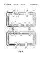
- FIG. 5 shows schematically one embodiment of the present invention.
- FIG. 6 shows schematically another embodiment of the present invention.
- FIG. 7 shows schematically a further embodiment of the present invention.
- FIG. 8 is a schematic illustration of a network made up of a plurality of rings connected by matched nodes.
- matched nodes use the working (in DCW mode) or protection (in the DCP mode) bandwidth of rings for the secondary path.
- the secondary path is only used under certain failure scenarios of the primary inter-ring connection.
- the bandwidth that is allocated for secondary paths cannot be used for anything else.
- either protection or working bandwidth which has been set aside for the secondary path is set to a “pass through” mode at any nodes which may be located between the primary and secondary nodes.
- no add/drop of traffic is permitted on that bandwidth set aside for the secondary path, thus limiting their capability as well as that of any other nodes on the rings which may want to communicate with these middle nodes.
- This bandwidth therefore does not generate any revenue and reduces over all capacity and capabilities of the ring.
- the use of secondary path bandwidth is of great concern for network operators who employ particularly large OC192 networks.
- the invention does not require the secondary path to be set aside in the matched nodes environment. This invention makes it possible to use the bandwidth which would have been unavailable to generate additional revenue.
- the present invention makes no use of the secondary path but uses the ring protection bandwidth to reroute traffic in case of a primary path or primary node failure (i.e., a failure in the primary inter-ring connection).
- Nodes in the rings are regular network elements such as add/drop multiplexers.
- the primary and secondary nodes and inter-ring connections are provisioned initially but neither service selectors nor drop-and-continue functionality is needed at the primary nodes.
- the invention uses the already available ring protection bandwidth for “secondary connection”. The invention hence frees up this bandwidth for other use which would normally have to be set aside for the secondary path.
- FIG. 5 illustrates one such embodiment of the invention.
- This embodiment includes a protection mechanism of the invention and would solve the problem of a primary inter-ring circuit failure.
- both primary nodes NE 6 and NE 8 will detect this condition by detecting a Loss of Signal (LOS or LAIS signals) on their tributaries.
- the both primary nodes are equipped with a protection module 102 and 104 which performs selective protection procedure in their own ring. According to this procedure, upon detecting a LOS or LAIS on its tributaries, a primary node performs a selective ring switch and reroute the affected traffic to the protection bandwidth.
- LOS or LAIS signals Loss of Signal
- the protection module 102 or 104 includes a detection module for detecting a failure, a signaling module for sending messages in the form of protocol signals to other nodes in its own ring and a protocol module for setting the protocol signals to inform of the failure and trigger a selective ring switch at the secondary node. While a ring switch according to the known BLSR protection mechanisms will reroute at a node the whole traffic on the working bandwidth to the protection bandwidth, the selective ring switch reroute only affected bandwidth, leaving other bandwidth nonimpacted. Therefore the local traffic is continued to be added/dropped on the unaffected bandwidths at the node where a selective ring switch is taking place.
- the secondary node NE 3 performs a selective ring switch and will pick up the affected traffic and drop it to its tributary (inter-ring connection between the two rings) from the protection bandwidths. If the other BLSR ring is equipped with the present invention, similar selective ring switches are performed at NE 8 and NE 10 , initiated by the protection module 104 at NE 8 .
- NE 8 when NE 8 fails, other primary node NE 6 will detect a LOS or LAIS.
- the protection module 202 executes similar procedure described above in ring 250 which includes a selective ring switch at NE 3 and NE 6 for the traffic that was dropped over the primary path (inter-ring circuit at NE 6 ).
- a node failure 254 at NE 8 would trigger the execution of regular protection mechanisms, which include a ring switch at neighboring nodes, e.g. NE 9 and NE 12 , as shown in the figure.
- FIG. 7 shows schematically the invention according to a further embodiment.
- the figures illustrates a fault 300 at NE 8 or a break 302 in the inter-ring circuit (primary path).
- NE 6 detects a loss-of-signal at its tributary.
- the protection module 304 would initiate a selective ring switch in ring 350 .
- NE 3 is the secondary node for this path and perform a selective ring switch in response to the indication from the primary node of a failure condition.
- a selective ring switch performed on the primary node may result in a long path to the secondary node, e.g.
- the protocol can direct to any node in the same ring to perform the selective ring switch.
- a selective ring switch can be performed at NE 7 or more commonly at NE 1 (source node or service access point) as shown in FIG. 7 . Due to the topology of the ring and other network parameters, it may be important to execute the ring switch at a certain node because it will result in shorter rerouting protection path, or other desirable performance.
- the ring switches can perform switch-over of a whole fiber as well as of only a specifically affected bandwidth.
- a selective ring switch of affected bandwidths is described in the embodiments thus far in which if a failure affects only one bandwidth of a connection between two communicating nodes, all other connections which are not affected by the failure will not be switched. Nodes in these embodiment includes protocol modules which allow selective ring switch of one or more certain bandwidths. It should of course noted that under certain circumstances, a regular ring switch of the whole bandwidths can be equally used to implement the inventive concept. It should further be noted that although breaks and failures are shown thus far to affect in two directions, it is possible for only one direction to fail. In regular practice, however, as both directions are often collocated, a failure in one direction would trigger protection mechanisms for both directions.
- FIG. 8 three or more rings are connected by matched nodes.
- P and S signify primary and secondary nodes. It illustrates that two or more rings can be considered as one larger ring and a failure in one ring could cause a selective ring switch in the larger ring.
- a failure of a primary node in ring 2 will cause a selective ring switch in ring 1 and a ring switch in ring 2 .
- the primary node in ring 2 becomes a “node” of ring 1 .
- ring 3 in the Figure extends to the primary nodes in ring 2 and 4 .
Abstract
Description
Claims (8)
Priority Applications (2)
| Application Number | Priority Date | Filing Date | Title |
|---|---|---|---|
| US09/339,254 US6259837B1 (en) | 1999-06-24 | 1999-06-24 | Optical inter-ring protection having matched nodes |
| CA002311399A CA2311399A1 (en) | 1999-06-24 | 2000-06-08 | Optical inter-ring protection having matched nodes |
Applications Claiming Priority (1)
| Application Number | Priority Date | Filing Date | Title |
|---|---|---|---|
| US09/339,254 US6259837B1 (en) | 1999-06-24 | 1999-06-24 | Optical inter-ring protection having matched nodes |
Publications (1)
| Publication Number | Publication Date |
|---|---|
| US6259837B1 true US6259837B1 (en) | 2001-07-10 |
Family
ID=23328180
Family Applications (1)
| Application Number | Title | Priority Date | Filing Date |
|---|---|---|---|
| US09/339,254 Expired - Lifetime US6259837B1 (en) | 1999-06-24 | 1999-06-24 | Optical inter-ring protection having matched nodes |
Country Status (2)
| Country | Link |
|---|---|
| US (1) | US6259837B1 (en) |
| CA (1) | CA2311399A1 (en) |
Cited By (22)
| Publication number | Priority date | Publication date | Assignee | Title |
|---|---|---|---|---|
| US6321004B1 (en) | 2001-04-24 | 2001-11-20 | Seneca Networks | Protection switching in bidirectional WDM optical communication networks |
| US6400859B1 (en) * | 1999-06-24 | 2002-06-04 | Nortel Networks Limited | Optical ring protection having matched nodes and alternate secondary path |
| US20020071148A1 (en) * | 2000-12-12 | 2002-06-13 | Purse Christopher M. | Optical communications network and nodes for forming such a network |
| US20020141334A1 (en) * | 2001-03-28 | 2002-10-03 | Deboer Evert E. | Dynamic protection bandwidth allocation in BLSR networks |
| US6616349B1 (en) * | 1999-12-20 | 2003-09-09 | Corning Incorporated | Two-fiber interconnected ring architecture |
| US20030206515A1 (en) * | 2000-05-26 | 2003-11-06 | Alcatel | Interconnection between telecommunication MS-SPRING and SNCP RING networks |
| EP1417796A2 (en) * | 2001-08-13 | 2004-05-12 | Tellabs Operations, Inc. | Inter-working mesh telecommunications networks |
| WO2005081435A1 (en) | 2004-02-20 | 2005-09-01 | Ericsson Ab | Communication network protection systems |
| US20050275340A1 (en) * | 2002-03-15 | 2005-12-15 | Lg Philips Lcd Co., Ltd. | Organic electroluminescent device including transparent conductive layer and fabricating method thereof |
| WO2006067194A1 (en) * | 2004-12-23 | 2006-06-29 | Ericsson Ab | Atm protection system |
| US7072580B2 (en) * | 2000-05-31 | 2006-07-04 | Cisco Technology, Inc. | Autoprotected optical communication ring network |
| US7170851B1 (en) * | 2001-07-26 | 2007-01-30 | Ciena Corporation | Systems and methods for automatic topology provisioning for SONET networks |
| US7209436B1 (en) * | 2000-12-30 | 2007-04-24 | Redback Networks Inc. | Method and apparatus for variable rate pipes |
| US20070220175A1 (en) * | 2006-03-17 | 2007-09-20 | Sanjay Khanna | Method and apparatus for media distribution using VPLS in a ring topology |
| US20070217331A1 (en) * | 2006-03-17 | 2007-09-20 | Sanjay Khanna | Method and apparatus for managing faults in a ring network |
| US20070237072A1 (en) * | 2006-04-07 | 2007-10-11 | Sbc Knowledge Ventures, L.P. | Resilient ip ring protocol and architecture |
| US7385917B1 (en) * | 2000-05-05 | 2008-06-10 | Fujitsu Limited | Method and system for providing a protection path for connectionless signals in a telecommunications network |
| US20090107315A1 (en) * | 2005-05-03 | 2009-04-30 | Blickle Sondermaschinen Gmbh & Co. Kg | Device for Rotary Processing of Rolled Materials |
| US20120089861A1 (en) * | 2010-10-12 | 2012-04-12 | International Business Machines Corporation | Inter-processor failure detection and recovery |
| US8554947B1 (en) * | 2003-09-15 | 2013-10-08 | Verizon Laboratories Inc. | Network data transmission systems and methods |
| GB2504172A (en) * | 2012-07-18 | 2014-01-22 | Fujitsu Ltd | Switch in interconnection coupling network ring which loops back some data in the event of an interconnection failure |
| US11658888B2 (en) | 2021-05-19 | 2023-05-23 | Ciena Corporation | Network timing trail visualization and method of troubleshooting |
Citations (1)
| Publication number | Priority date | Publication date | Assignee | Title |
|---|---|---|---|---|
| US6046833A (en) * | 1997-02-10 | 2000-04-04 | Optical Networks, Inc. | Method and apparatus for operation, protection, and restoration of heterogeneous optical communication networks |
-
1999
- 1999-06-24 US US09/339,254 patent/US6259837B1/en not_active Expired - Lifetime
-
2000
- 2000-06-08 CA CA002311399A patent/CA2311399A1/en not_active Abandoned
Patent Citations (1)
| Publication number | Priority date | Publication date | Assignee | Title |
|---|---|---|---|---|
| US6046833A (en) * | 1997-02-10 | 2000-04-04 | Optical Networks, Inc. | Method and apparatus for operation, protection, and restoration of heterogeneous optical communication networks |
Cited By (37)
| Publication number | Priority date | Publication date | Assignee | Title |
|---|---|---|---|---|
| US6400859B1 (en) * | 1999-06-24 | 2002-06-04 | Nortel Networks Limited | Optical ring protection having matched nodes and alternate secondary path |
| US6616349B1 (en) * | 1999-12-20 | 2003-09-09 | Corning Incorporated | Two-fiber interconnected ring architecture |
| US7385917B1 (en) * | 2000-05-05 | 2008-06-10 | Fujitsu Limited | Method and system for providing a protection path for connectionless signals in a telecommunications network |
| US7035203B2 (en) * | 2000-05-26 | 2006-04-25 | Alcatel | Interconnection between telecommunication MS-SPRING and SNCP ring networks |
| US20030206515A1 (en) * | 2000-05-26 | 2003-11-06 | Alcatel | Interconnection between telecommunication MS-SPRING and SNCP RING networks |
| US7072580B2 (en) * | 2000-05-31 | 2006-07-04 | Cisco Technology, Inc. | Autoprotected optical communication ring network |
| US20020071148A1 (en) * | 2000-12-12 | 2002-06-13 | Purse Christopher M. | Optical communications network and nodes for forming such a network |
| US6816680B2 (en) * | 2000-12-12 | 2004-11-09 | Nortel Networks Limited | Optical communications network and nodes for forming such a network |
| US7209436B1 (en) * | 2000-12-30 | 2007-04-24 | Redback Networks Inc. | Method and apparatus for variable rate pipes |
| US20020141334A1 (en) * | 2001-03-28 | 2002-10-03 | Deboer Evert E. | Dynamic protection bandwidth allocation in BLSR networks |
| US6321004B1 (en) | 2001-04-24 | 2001-11-20 | Seneca Networks | Protection switching in bidirectional WDM optical communication networks |
| US7170851B1 (en) * | 2001-07-26 | 2007-01-30 | Ciena Corporation | Systems and methods for automatic topology provisioning for SONET networks |
| EP1417796A4 (en) * | 2001-08-13 | 2009-03-25 | Tellabs Operations Inc | Inter-working mesh telecommunications networks |
| EP1417796A2 (en) * | 2001-08-13 | 2004-05-12 | Tellabs Operations, Inc. | Inter-working mesh telecommunications networks |
| US20050275340A1 (en) * | 2002-03-15 | 2005-12-15 | Lg Philips Lcd Co., Ltd. | Organic electroluminescent device including transparent conductive layer and fabricating method thereof |
| US8554947B1 (en) * | 2003-09-15 | 2013-10-08 | Verizon Laboratories Inc. | Network data transmission systems and methods |
| WO2005081435A1 (en) | 2004-02-20 | 2005-09-01 | Ericsson Ab | Communication network protection systems |
| US8203931B2 (en) * | 2004-02-20 | 2012-06-19 | Ericsson Ab | Communication network protection systems |
| CN1973466B (en) * | 2004-02-20 | 2011-09-28 | 爱立信股份有限公司 | Communication network protection systems and communication network |
| US20080219156A1 (en) * | 2004-02-20 | 2008-09-11 | Diego Caviglia | Communication Network Protection Systems |
| US20090034422A1 (en) * | 2004-12-23 | 2009-02-05 | Francesco Pasio | ATM Protection System |
| WO2006067194A1 (en) * | 2004-12-23 | 2006-06-29 | Ericsson Ab | Atm protection system |
| US20090107315A1 (en) * | 2005-05-03 | 2009-04-30 | Blickle Sondermaschinen Gmbh & Co. Kg | Device for Rotary Processing of Rolled Materials |
| US7971525B2 (en) * | 2005-05-03 | 2011-07-05 | Blickle Sondermaschinen Gmbh & Co. Kg | Device for rotary processing of rolled materials |
| US20070217331A1 (en) * | 2006-03-17 | 2007-09-20 | Sanjay Khanna | Method and apparatus for managing faults in a ring network |
| US7852754B2 (en) * | 2006-03-17 | 2010-12-14 | Tellabs San Jose, Inc. | Method and apparatus for managing faults in a ring network |
| US9083551B2 (en) | 2006-03-17 | 2015-07-14 | Tellabs Operations, Inc. | Method and apparatus for media distribution using VPLS in a ring topology |
| US20070220175A1 (en) * | 2006-03-17 | 2007-09-20 | Sanjay Khanna | Method and apparatus for media distribution using VPLS in a ring topology |
| US8570857B2 (en) * | 2006-04-07 | 2013-10-29 | At&T Intellectual Property I, Lp | Resilient IP ring protocol and architecture |
| US20070237072A1 (en) * | 2006-04-07 | 2007-10-11 | Sbc Knowledge Ventures, L.P. | Resilient ip ring protocol and architecture |
| US8850262B2 (en) * | 2010-10-12 | 2014-09-30 | International Business Machines Corporation | Inter-processor failure detection and recovery |
| US20120089861A1 (en) * | 2010-10-12 | 2012-04-12 | International Business Machines Corporation | Inter-processor failure detection and recovery |
| GB2504172A (en) * | 2012-07-18 | 2014-01-22 | Fujitsu Ltd | Switch in interconnection coupling network ring which loops back some data in the event of an interconnection failure |
| US20140025985A1 (en) * | 2012-07-18 | 2014-01-23 | Fujitsu Limited | Communication control device and communication control method |
| US9075769B2 (en) * | 2012-07-18 | 2015-07-07 | Fujitsu Limited | Communication control device and communication control method |
| GB2504172B (en) * | 2012-07-18 | 2016-09-07 | Fujitsu Ltd | Communication control device and communication control method |
| US11658888B2 (en) | 2021-05-19 | 2023-05-23 | Ciena Corporation | Network timing trail visualization and method of troubleshooting |
Also Published As
| Publication number | Publication date |
|---|---|
| CA2311399A1 (en) | 2000-12-24 |
Similar Documents
| Publication | Publication Date | Title |
|---|---|---|
| US6259837B1 (en) | Optical inter-ring protection having matched nodes | |
| US6400859B1 (en) | Optical ring protection having matched nodes and alternate secondary path | |
| Wu et al. | A class of self-healing ring architectures for SONET network applications | |
| US7426179B1 (en) | Method and apparatus for signaling path restoration information in a mesh network | |
| US5974027A (en) | Telecommunications network including a channel switching protection arrangement | |
| EP1083689B1 (en) | A method of sending routing data across a network and a network node using the method | |
| US7352966B2 (en) | Method and apparatus for capacity-efficient restoration in an optical communication system | |
| US7319662B2 (en) | Virtual line switched ring | |
| US6707789B1 (en) | Flexible SONET ring with integrated cross-connect system | |
| US20080285440A1 (en) | Mesh with protection channel access (MPCA) | |
| EP0984574B1 (en) | Backwards-compatible failure restoration in bidirectional multiplex section-switched ring transmission systems | |
| US6579018B1 (en) | Four-fiber ring optical cross connect system using 4×4 switch matrices | |
| JPH07112203B2 (en) | Dual hub device providing ring interconnect protection | |
| WO2002069540A2 (en) | Method and system for a bi-directional path switched network | |
| US6904542B2 (en) | System for group-based distributed protection switching | |
| US7145882B2 (en) | Multiplexed automatic protection switching channels | |
| US20040221058A1 (en) | Nested protection switching in a mesh connected communications network | |
| US6337846B1 (en) | Quantification of the quality of spare links in a telecommunications network | |
| EP1158831B1 (en) | Interconnection between telecommunication MS-SPRING and SNCP ring networks | |
| US20030235152A1 (en) | Network system incorporating protection paths in the transmission bandwidth of a virtual concatenation signal | |
| US20030172315A1 (en) | Method of restoring a facility failure in a communication network, a communication network, a network element, a protocol, a program module and a communication interface module therefor | |
| US6950883B1 (en) | Ring capacity efficient architecture | |
| US7512060B1 (en) | Method and apparatus for providing a connection matrix | |
| CA2356643C (en) | Virtual line switched ring | |
| JP2000041056A (en) | Line relieving method and ring network using the method |
Legal Events
| Date | Code | Title | Description |
|---|---|---|---|
| AS | Assignment |
Owner name: NORTEL NETWORKS CORPORATION, CANADA Free format text: ASSIGNMENT OF ASSIGNORS INTEREST;ASSIGNORS:DE BOER, EVERT;PHELPS, PETER WILLIAM;PARE, LOUIS RENE;AND OTHERS;REEL/FRAME:010073/0150;SIGNING DATES FROM 19990614 TO 19990616 |
|
| AS | Assignment |
Owner name: NORTEL NETWORKS LIMITED, CANADA Free format text: CHANGE OF NAME;ASSIGNOR:NORTEL NETWORKS CORPORATION;REEL/FRAME:011195/0706 Effective date: 20000830 Owner name: NORTEL NETWORKS LIMITED,CANADA Free format text: CHANGE OF NAME;ASSIGNOR:NORTEL NETWORKS CORPORATION;REEL/FRAME:011195/0706 Effective date: 20000830 |
|
| FEPP | Fee payment procedure |
Free format text: PAYER NUMBER DE-ASSIGNED (ORIGINAL EVENT CODE: RMPN); ENTITY STATUS OF PATENT OWNER: LARGE ENTITY Free format text: PAYOR NUMBER ASSIGNED (ORIGINAL EVENT CODE: ASPN); ENTITY STATUS OF PATENT OWNER: LARGE ENTITY |
|
| STCF | Information on status: patent grant |
Free format text: PATENTED CASE |
|
| FPAY | Fee payment |
Year of fee payment: 4 |
|
| FPAY | Fee payment |
Year of fee payment: 8 |
|
| AS | Assignment |
Owner name: CIENA LUXEMBOURG S.A.R.L.,LUXEMBOURG Free format text: ASSIGNMENT OF ASSIGNORS INTEREST;ASSIGNOR:NORTEL NETWORKS LIMITED;REEL/FRAME:024213/0653 Effective date: 20100319 Owner name: CIENA LUXEMBOURG S.A.R.L., LUXEMBOURG Free format text: ASSIGNMENT OF ASSIGNORS INTEREST;ASSIGNOR:NORTEL NETWORKS LIMITED;REEL/FRAME:024213/0653 Effective date: 20100319 |
|
| AS | Assignment |
Owner name: CIENA CORPORATION,MARYLAND Free format text: ASSIGNMENT OF ASSIGNORS INTEREST;ASSIGNOR:CIENA LUXEMBOURG S.A.R.L.;REEL/FRAME:024252/0060 Effective date: 20100319 Owner name: CIENA CORPORATION, MARYLAND Free format text: ASSIGNMENT OF ASSIGNORS INTEREST;ASSIGNOR:CIENA LUXEMBOURG S.A.R.L.;REEL/FRAME:024252/0060 Effective date: 20100319 |
|
| FPAY | Fee payment |
Year of fee payment: 12 |
|
| AS | Assignment |
Owner name: DEUTSCHE BANK AG NEW YORK BRANCH, NEW YORK Free format text: SECURITY INTEREST;ASSIGNOR:CIENA CORPORATION;REEL/FRAME:033329/0417 Effective date: 20140715 |
|
| AS | Assignment |
Owner name: BANK OF AMERICA, N.A., AS ADMINISTRATIVE AGENT, NO Free format text: PATENT SECURITY AGREEMENT;ASSIGNOR:CIENA CORPORATION;REEL/FRAME:033347/0260 Effective date: 20140715 |
|
| AS | Assignment |
Owner name: CIENA CORPORATION, MARYLAND Free format text: RELEASE BY SECURED PARTY;ASSIGNOR:DEUTSCHE BANK AG NEW YORK BRANCH;REEL/FRAME:050938/0389 Effective date: 20191028 |
|
| AS | Assignment |
Owner name: BANK OF AMERICA, N.A., AS COLLATERAL AGENT, ILLINO Free format text: PATENT SECURITY AGREEMENT;ASSIGNOR:CIENA CORPORATION;REEL/FRAME:050969/0001 Effective date: 20191028 |
|
| AS | Assignment |
Owner name: CIENA CORPORATION, MARYLAND Free format text: RELEASE BY SECURED PARTY;ASSIGNOR:BANK OF AMERICA, N.A.;REEL/FRAME:065630/0232 Effective date: 20231024 |