EP0984574B1 - Backwards-compatible failure restoration in bidirectional multiplex section-switched ring transmission systems - Google Patents
Backwards-compatible failure restoration in bidirectional multiplex section-switched ring transmission systems Download PDFInfo
- Publication number
- EP0984574B1 EP0984574B1 EP99306650A EP99306650A EP0984574B1 EP 0984574 B1 EP0984574 B1 EP 0984574B1 EP 99306650 A EP99306650 A EP 99306650A EP 99306650 A EP99306650 A EP 99306650A EP 0984574 B1 EP0984574 B1 EP 0984574B1
- Authority
- EP
- European Patent Office
- Prior art keywords
- node
- connection
- path
- jumpered
- jumper
- Prior art date
- Legal status (The legal status is an assumption and is not a legal conclusion. Google has not performed a legal analysis and makes no representation as to the accuracy of the status listed.)
- Expired - Lifetime
Links
- 230000005540 biological transmission Effects 0.000 title claims description 52
- 230000002457 bidirectional effect Effects 0.000 title claims description 12
- 238000012545 processing Methods 0.000 claims description 38
- 238000004891 communication Methods 0.000 claims description 24
- 238000000034 method Methods 0.000 claims description 16
- 230000004044 response Effects 0.000 claims description 11
- 230000003287 optical effect Effects 0.000 description 10
- 230000000644 propagated effect Effects 0.000 description 10
- 239000013307 optical fiber Substances 0.000 description 8
- 230000009471 action Effects 0.000 description 6
- 238000012790 confirmation Methods 0.000 description 5
- 238000010586 diagram Methods 0.000 description 5
- 230000000694 effects Effects 0.000 description 5
- 239000000835 fiber Substances 0.000 description 5
- 230000001902 propagating effect Effects 0.000 description 4
- 230000001360 synchronised effect Effects 0.000 description 4
- 230000015556 catabolic process Effects 0.000 description 3
- 230000008859 change Effects 0.000 description 3
- 230000006735 deficit Effects 0.000 description 3
- 238000006731 degradation reaction Methods 0.000 description 3
- 230000008569 process Effects 0.000 description 3
- 230000001934 delay Effects 0.000 description 2
- 230000001419 dependent effect Effects 0.000 description 1
- 238000001514 detection method Methods 0.000 description 1
- 230000006870 function Effects 0.000 description 1
- 229910000078 germane Inorganic materials 0.000 description 1
- RGNPBRKPHBKNKX-UHFFFAOYSA-N hexaflumuron Chemical compound C1=C(Cl)C(OC(F)(F)C(F)F)=C(Cl)C=C1NC(=O)NC(=O)C1=C(F)C=CC=C1F RGNPBRKPHBKNKX-UHFFFAOYSA-N 0.000 description 1
- 238000003780 insertion Methods 0.000 description 1
- 230000037431 insertion Effects 0.000 description 1
- 230000008054 signal transmission Effects 0.000 description 1
- PPASLZSBLFJQEF-RKJRWTFHSA-M sodium ascorbate Substances [Na+].OC[C@@H](O)[C@H]1OC(=O)C(O)=C1[O-] PPASLZSBLFJQEF-RKJRWTFHSA-M 0.000 description 1
Images


Classifications
-
- H—ELECTRICITY
- H04—ELECTRIC COMMUNICATION TECHNIQUE
- H04J—MULTIPLEX COMMUNICATION
- H04J3/00—Time-division multiplex systems
- H04J3/02—Details
- H04J3/08—Intermediate station arrangements, e.g. for branching, for tapping-off
- H04J3/085—Intermediate station arrangements, e.g. for branching, for tapping-off for ring networks, e.g. SDH/SONET rings, self-healing rings, meashed SDH/SONET networks
-
- H—ELECTRICITY
- H04—ELECTRIC COMMUNICATION TECHNIQUE
- H04J—MULTIPLEX COMMUNICATION
- H04J2203/00—Aspects of optical multiplex systems other than those covered by H04J14/05 and H04J14/07
- H04J2203/0001—Provisions for broadband connections in integrated services digital network using frames of the Optical Transport Network [OTN] or using synchronous transfer mode [STM], e.g. SONET, SDH
- H04J2203/0028—Local loop
- H04J2203/0039—Topology
- H04J2203/0042—Ring
-
- H—ELECTRICITY
- H04—ELECTRIC COMMUNICATION TECHNIQUE
- H04J—MULTIPLEX COMMUNICATION
- H04J2203/00—Aspects of optical multiplex systems other than those covered by H04J14/05 and H04J14/07
- H04J2203/0001—Provisions for broadband connections in integrated services digital network using frames of the Optical Transport Network [OTN] or using synchronous transfer mode [STM], e.g. SONET, SDH
- H04J2203/0057—Operations, administration and maintenance [OAM]
- H04J2203/006—Fault tolerance and recovery
Definitions
- This invention relates to bidirectional multiplex section-switched ring transmission systems and, more particularly, to a failure restoration method and apparatus for use in such systems.
- bi-directional multiplex section switched self-healing ring transmission systems also referred to herein as bi-directional line-switched rings (BLSRs)
- BLSRs bi-directional line-switched rings
- the length of the restoration path would be looped and may cause signals to traverse the ocean three times for particular fault conditions making the path extremely long, causing long delays and degraded system performance. The long delays and degraded service is extremely undesirable.
- BLSR line switched ring
- each node sends a subsequent node address contained in an APS byte of the K1 and K2 bytes in a multiplexed signal overhead to the subsequent node.
- each node adjacent the trouble sends the address of the node normally connected thereto via the troubled line.
- Each node of the network is provided with a bypass circuit for the APS byte and an address comparison circuit for comparing the address in the APS byte with a current node address.
- Each node closes the bypass circuit and receives the APS byte when the result of comparison proves coincident, and opens the bypass circuit and allows passage of ASP byte when the result proves non-coincident.
- the prior restoration problems resulting from a system transmission path degradation are overcome, in accordance with the principles of the invention, by the use of a jumper flag indicating an establishment of a jumpered connection path, for each active tributary affected by the path degradation.
- the jumpered connection path at an affected node eliminates any unnecessary loop formed in the re-established connection path caused by the loopback connection at that node.
- each node there is stored in memory at each node entries identifying (1) its provisioned (or normal) service connection path and (2) a jumper flag indicating if a jumpered connection path exists.
- a loopback setup complete message received at a node from both the first and second directions, it is determined if a jumpered connection is needed at that node. If a jumpered connection is not needed, conventional BLSR processing is performed. If a jumpered connection is needed, the provisioned connection is taken down, the jumpered connection is put up, a jumper flag is set, and conventional BLSR processing is performed.
- a jumper flag is set at that node. If the jumper flag is set, the jumpered connection is taken down, the provisioned connection is restored, and the jumper flag is reset. If the jumper flag is not set, conventional BLSR processing is performed.
- the present invention describes a communication node for use in a bidirectional multiplex section-switched ring transmission system including a plurality of nodes and a first and second transmission paths, each transmission path including a service path and a protection path interconnecting said plurality of nodes and transporting communications signals around said system from node to node in a different transmission direction, said node detecting a trouble in the transmission path and rerouting a connection around the troubled transmission path, said node CHARACTERIZED BY:
- the operation of the present invention can be programmed into existing node controllers and is compatible with existing restoration procedures.
- each item or block of each figure has a reference designation associated therewith, the first number of which refers to the figure in which that item is first located (e.g., 104 is located in Fig. 1).
- Fig. 1 shows, in simplified form, BLSR transmission system 100, which for brevity and clarity of exposition is shown as including only ring nodes 101 through 104, each incorporating an embodiment of the invention. It will be apparent that additional or fewer ring nodes and different orientation of ring nodes may be employed, as desired.
- Ring nodes 101 through 104 are interconnected by transmission path 110, including service path 110-S and protection path 110-P, in a counter-clockwise direction, and by transmission path 120, including service path 120-S and protection path 120-P, in a clockwise direction.
- transmission paths 110 and 120 are each comprised of two (2) optical fibers. It will be apparent, however, each of transmission paths 110 and 120 could be comprised of a single optical fiber.
- bidirectional multiplex section-switched ring transmission system 100 could be either a two (2) optical fiber or a four (4) optical fiber system.
- each of the fibers in transmission paths 110 and 120 includes service bandwidth and protection bandwidth.
- each of transmission paths 110 and 120 includes an optical fiber for service bandwidth and a separate optical fiber for protection bandwidth.
- Such bidirectional multiplex section-switched ring transmission systems are known.
- transmission of digital signals in the CCITT Synchronous Digital Hierarchy (SDH) digital signal format is assumed.
- SDH Synchronous Digital Hierarchy
- the invention is equally applicable to other digital signal formats, for example, the ANSI SONET digital signal format.
- requests and acknowledgments for protection switch action are transmitted in an Automatic Protection Switch (APS) channel in the SDH multiplex section overhead accompanying the protection paths 110-P and 120-P on each of transmission paths 110 and 120.
- the APS channel in the SDH format, comprises the K1 and K2 bytes (shown in Fig. 6) in the SDH overhead of each of protection paths 110-P and 120-P.
- a "communications circuit" is considered to be a AU-4 SDH digital signal having its entry and exit points on the ring.
- Each of ring nodes 101 through 104 comprises an add-drop multiplexer (ADM).
- ADM add-drop multiplexer
- Such add-drop multiplexer arrangements are known.
- the ADM operates in a transmission sense to pass, i.e., express, signals through the ring node, to add signals at the ring node, to drop signals at the ring node, and to bridge and switch signals, in accordance with the principles of the invention, during a protection switch at the ring node.
- the ADM operates in a transmission sense to pass, i.e., express, signals through the ring node, to add signals at the ring node, to drop signals at the ring node, and to bridge and switch signals, in accordance with the principles of the invention, during a protection switch at the ring node.
- Note that in the event of a loop failure normal "loopbacks" of the affected signals in ring nodes adjacent to (i.e.,border) the failure occur in a well known manner in these bidirectional
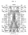
- Fig. 2 shows, in simplified block diagram form, details of ring nodes 101 through 104.
- a clockwise digital signal transmission direction is assumed in the service path 110-S and the protection path 110-P on transmission path 110. It will be apparent that operation of the ring node and the ADM therein would be similar for a counter-clockwise service path 120-S and the protection path 120-P on transmission path 120.
- service path 110-S and protection path 110-P entering the ring node and supplying STM-N SDH optical signals to receiver 201-S and receiver 201-P, respectively, where N is, for example, 16.
- service path 120-S and protection path 120-P entering the ring and supplying STM-N SDH optical signals to receiver 202-S and receiver 202-P, respectively, where N is, for example, 16.
- N is, for example, 16.
- receivers 201 and 202 are identical, and are shown in Fig. 3, to be described below.
- the SDH STM-N optical signals exit the ring node on service path 110-S as an output from transmitter 203-S, on service path 120-S as an output from transmitter 204-S, on protection path 110-P as an output from transmitter 203-P and on protection path 120-P as an output from transmitter 204-P.
- transmitters 203 and 204 are identical and are shown in Fig. 4, to be described below.
- AU-4 SDH output signals from receiver 201-S are routed under control of controller 210 either to transmitter 203-S, i.e., expressed through to service path 110-S, to interface 206-S to be dropped, also to interface 206-S for protection switching to interface 206-P where it will be dropped or to transmitter 203-P to be supplied to protection path 110-P.
- AU-4 SDH output signals from receiver 202-S are routed under control of controller 210 either to transmitter 204-S, i.e., expressed through to service path 120-S, to interface 207-S to be dropped, also to interface 206-S for protection switching to interface 206-P where it will be dropped or to transmitter 204-P to be supplied to protection path 120-P.
- the AU-4 signals from receiver 201-P are supplied either to transmitter 203-P, i.e., expressed through to protection path 110-P, to interface 206-S to be dropped or to transmitter 203-S to be supplied to service path 110-S.
- AU-4 signals from receiver 202-P are routed under control of controller 210 either to transmitter 204-P, i.e., expressed through to protection path 120-P, to interface 207-S to be dropped or to transmitter 204-S to be supplied to service path 120-S.
- AU-4 SDH signals being added and dropped via interface 206-S can be bridged to transmitter 203-P and, hence, protection path 110-P and can be switched from receiver 202-P and, hence, from protection path 120-P, all under control of controller 210.
- AU-4 SDH signals being added and dropped via interface 207-S can be bridged to transmitter 204-P and, hence, protection path 120-P and can be switched from receiver 201-P and, hence, from protection path 110-P, all under control of controller 210.
- Interfaces 206-S, 206-P, 207-S and 207-P are employed to interface to particular duplex links 216-S, 216-P, 217-S and 217, respectively, and could include any desired arrangement.
- interfaces 206 and 207 could include a CEPT-4 digital signal interface to a DSX, a STM-1E (electrical) SDH digital signal interfacing to a DSX, an optical extension interface to an STM-1 SDH optical signal or the like.
- Such interface arrangements are known.
- controller 210 uses the program shown in the flow charts of Fig. 10 (which are stored in memory 220) to control the adding, dropping, and bridging of the signals via interfaces 206 and 207, as well as, the direct bridging and switching of the AU-4 tributaries being added and dropped to and from protection paths 110-P and 120-P. Controller 210 also monitors the status of interfaces 206 and 207 and the digital signals supplied thereto via the control bus arrangement. Specifically, controller 210 monitors interfaces 206 and 207 for a signal failure condition, i.e., loss-of-signal, loss-of-frame, coding violations and the like. The controller also monitors for loopback completion, takedown completion, clear, and other messages.
- a signal failure condition i.e., loss-of-signal, loss-of-frame, coding violations and the like.
- Controller 210 operates to effect the jumpering (signal path to protection path connection), bridging, and switching of communications tributaries at ring nodes, if necessary. Controller 210 communicates with receivers 201 and 202, transmitters 203 and 204 and interfaces 206 and 207 via a control bus arrangement. Specifically, controller 210 monitors the incoming digital signals to determine loss-of-signal, SDH format K bytes (of Fig. 6) and the like. Additionally, controller 210 causes the insertion of appropriate K byte messages (of Fig. 6) for protection switching purposes, examples of which are described below.
- controller 210 is advantageously provisioned via bus 212 with the identities (IDs) of all the communications tributaries passing through the ring node, as well as, those communications tributaries being added and/or dropped at the ring node (stored in tables of Fig. 7 - 9), the identity of all the ring nodes in system 100 and the positions of the ring nodes in system 100 (stored in Fig. 5).
- IDs identities
- controller 210 is advantageously provisioned via bus 212 with the identities (IDs) of all the communications tributaries passing through the ring node, as well as, those communications tributaries being added and/or dropped at the ring node (stored in tables of Fig. 7 - 9), the identity of all the ring nodes in system 100 and the positions of the ring nodes in system 100 (stored in Fig. 5).
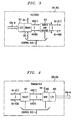
- Fig. 3 shows, in simplified form, details of receivers 201 and 202 of Fig. 2.
- the receiver includes an optical/electrical (O/E) interface 301, demultiplexer (DEMUX) 302 and driver and router 303.
- An STM-N SDH optical signal is supplied to O/E 301 which converts it to an electrical STM-N signal.
- the AUG (1) through AUG (N) signals are supplied to driver and router 303 where they are routed under control of controller 210 via the control bus as AU-4 (1) through AU-4 (M) SDH signals.
- each STM-N signal can include N AUG tributaries, in this example.
- the AU-4 (1) through AU-4 (M) signals are routed under control of controller 210, as described above regarding Fig. 2.
- DEMUX 302 also re-moves STM overhead (OH), and supplies the APS channel K bytes to controller 210 via the control bus.
- Fig. 4 shows, in simplified form, details of transmitters 203 and 204 of Fig. 2.
- the transmitter includes select unit 401, multiplexer (MUX) 402 and etectrical/optical interface (E/O) 403.
- the AUG tributaries are supplied to MUX 402 where overhead (OH) is added to yield an electrical STM-N SDH signal.
- E/O interface 403 converts the STM-N into an optical STM-N for transmission on the corresponding fiber transmission path.
- MUX 402 also inserts appropriate K byte messages under control of controller 210 via the control bus.
- Fig. 5 shows a ring node map table including the node identification (ID) of and relative location of each of ring nodes 101 through 104 of system 100.
- the ring node map table is provisioned via 212 in memory of controller 210.
- the K1 byte indicates a re-quest of a communications tributary for switch action.
- the first four (4) bits of the K1 byte indicate the switch re-quest priority and the last four (4) bits indicate the ring node identification (ID) of the destination ring node.
- the K2 byte indicates an acknowledgment of the requested protection switch action.
- the first four (4) bits of the K2 byte indicate the ring node ID of the source ring node and the last 4 bits indicate the action taken.
- the first four bits of the K1 bytes are "priority" field which indicated the type of system message, e.g., idle, SF-loop, clear, loopback complete, takedown, etc.
- the fifth bit of K2 bytes is a long/short bit which indicates the path length.
- the last three bits of the K2 bytes are called "action taken" field , e.g., idle, FERF (far end remote failure), etc.
- FIGs. 7 - 9 are illustrative node traffic tables for ring nodes 104, 101, and 102, respectively. These node traffic tables include the identification of the ring node communications traffic, i.e., the active communications tributaries, in both the clockwise (CW) direction and the counter-clockwise (CCW) direction of transmission. The active communications tributaries include those being added, dropped, bridged or expressed through the nodes 104, 101, and 102.
- Our illustrative tributary signal "X" connection shown in Fig. 1, enters node 104 and is routed via node 101 and exits at node 102.
- the tables of FIGs 7 - 9 include the IDs of active communications tributaries in the clockwise (CW) direction (shown as 701, 801, and 901, respectively) and counter-CW (CCW) direction (shown as 710, 810, and 910, respectively). These tables identify the tributaries (using AU-4#s), the "provisioned" destination paths of those tributaries, and the jumper statuses. Shown in the node 104 table of Fig. 7 is the AU-4 tributary identification, i.e., X in our example. As previously noted, the number of AU-4 tributaries can be up to 16. As shown in Fig.
- the provisioned connection 711 is designated 102 (s7) indicating that CW service channel 7 carries the X signal to node 102.
- the provisioned connection 811 is designated 104 (s7) indicating that CW service channel 7 carries the X signal from node 104.
- the provisioned connection 911 is designated T (S7) indicating that CW service channel 7 carries the X signal in an express manner, i.e., the X signal passes through rather than entering or exiting at this node.
- the X signal path after the transmission path break is shown as 721, 821, 921 in Figs. 7, 8, and 9 , respectively.
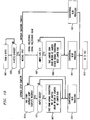
- Fig. 10 is a flow chart illustrating the operation of controller 210, in accordance with the invention, in controlling the operation of the ring nodes in order to effect the bridging and switching of tributary traffic paths in the presence of a ring impairment or removal of the impairment.
- a ring impairment is defined as a failure or degradation of the signals from any cause including failure of the transmission paths or of the equipment. It should be noted that all so-called part-time service which was being transported on the protection paths 110-P and 120-P is preempted upon detection of the failure. Thus, the part-time service is taken off of the protection paths 110- P and 120- P.
- the controller runs the process shown in the flowchart.
- the controller 210 loops between steps 1003 and 1001 perpetually checking for a change in the content of K bytes (of Fig. 6) of an incoming STM-N signal. If a change in the content of the K bytes is detected, then the process continues on to 1005; if not, it returns to 1001.
- the controller will take one of three branches depending on whether the new K-byte content indicates one of the following: (1) signal failure/degrade or clear, (2) loopback setup complete, or (3) loopback takedown complete. All other K-byte content changes are handled according to the rules laid down in the BLSR processing document (ITU-T G.841)
- control is passed to1013, which returns the controller to the wait loop of 1001.
- step involving the jumpered circuits is a null step, for no jumpers can exist at this point.
- step (2) it has been explicitly culled out to make it symmetrical with step (2).
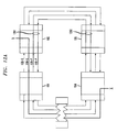
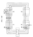
- Figs. 11 through 16 provide an illustration of the operation of the present invention for a single failure occurring within a normally operating ring, and will make reference to Figs. 7 through 10.
- the following description assumes that an X signal tributary connection has been established, in a well known manner, to enter node 104 and traverse node 101 and exit at node 102, as is shown in Fig. 11.
- the node tables for nodes 104, 102, and 101, shown in Figs. 7 - 9, respectively, have stored therein the "provisioned" connection information, in a well known manner, as depicted by 711, 811, and 911.
- a complete fiber cut fault has occurred between nodes 101 and 104.
- a cable cut interrupts the transmission of the X signal tributary (the two directions of the signal being indicated by bold lines).
- Nodes 101 and 104 which border the cable cut, determine that a failure has occurred and propagate a failure message via the K-bytes in both CW and CCW directions.
- both border nodes 101 and 104 are concurrently sending messages to the next node of the system (i.e., node 101 is sending to node 102 and node 104 to node 103).
- the controller When the failure message is received at node 102, the controller, having detected a change in the K-bytes, ceases looping at 1003, checks the message at 1005, and proceeds to step 1007, where it checks the jumper flag.
- the jumper flag In this example, we are assuming that the ring was unimpaired prior to the fiber cut fault, hence the jumper flag is not set, and therefore, control passes directly to step 1011. Normal BLSR processing is performed which consists of putting up a protection pass through 1201, which allows onward propagation of the K-bytes to node 103.
- step 1005 the receipt of the K-bytes at node 104 causes its controller to pass to step 1005.
- step 1005 There are no jumpers, so control passes on to 1011 and normal BLSR operation takes place - in this case this comprises the setting up of signal loopback 1203.
- Fig. 12b shows the signal "X" connection 1205 after each border node 104 and 101 has received the "failure" message which originated from the other border node and has performed a loopback connection.
- step 1011 the controllers of border nodes 101 and 104 then propagated a "loopback complete" confirmation message to the other system nodes. Control at the border nodes then returns, via step 1013, to looping at steps 1001-1003.
- step 1014 the "loopback complete" message from node 101 is received before the one from node 104 arrives, step 1014 is performed, and control is transferred to normal BLSR processing in step 1019, which does nothing further than pass on the "loopback complete" K-bytes.
- step 1014 When the "loopback complete" message from node 104 is received at node 102, it performs step 1014 and proceeds on to step 1015, since the other loopback complete message (i.e., the one from node 101) has already been received.
- step 1015 a jumper is needed, since the X signal tributary will need to be received from (and transmitted to) the right-hand side in order to eliminate the loop formed to the left.
- Step 1017 causes node 102 to remove provisioned connection 1205 and passthrough connection 1206 of Fig. 12b, and put in jumpers (1301 of Figs. 13a and 13b), and set the jumper flag (column 804 of row 821 of Fig. 8). Note that the record of the originally provisioned connection is maintained in the node's memory (column 803 of Fig. 8) for subsequent restoral.
- Node 102 then propagates the loopback completion message CCW to node 101, where per normal BLSR operation, steady state is reached. Control at 102 also returns to steady state (looping at 1001-1003) via step 1013.
- step 1003 the clear message is originated at both of the border nodes 101 and 104 and is propagated via node 102 and 103, respectively.
- step 1007 the jumper flag is checked; since the flag is set indicating that a jumper exists at node 102 (see column 804 and row 821 of Fig. 8) the controller performs step 1009, and (1) the jumpered connection is taken down, (2) normal (i.e., provisioned) circuit connections restored, and (3) the jumper flag reset.
- step 1011 whereupon normal BLSR processing is performed, which in this case means that the nodes propagates the clear message to the next node, 103.
- step 1013 the clear message
- the clear message is similarly processed in node 103, where it is merely passed through since there are no jumpers set at that node.
- the takedown confirmation messages from node 104 is propagated back through nodes 103 and 102 to 101, and similarly the takedown confirmation messages from node 101 is propagated back through nodes 102 and 103 to 104, with regular BLSR processing being performed at all nodes per step 1021 in Fig. 10, and stable operation is reached.
Landscapes
- Engineering & Computer Science (AREA)
- Computer Networks & Wireless Communication (AREA)
- Signal Processing (AREA)
- Small-Scale Networks (AREA)
- Time-Division Multiplex Systems (AREA)
Description
- This invention relates to bidirectional multiplex section-switched ring transmission systems and, more particularly, to a failure restoration method and apparatus for use in such systems.
- In prior known bidirectional multiplex section switched self-healing ring transmission systems (also referred to herein as bi-directional line-switched rings (BLSRs)), bridging and switching, in the presence of a fault, was restricted to switching at the BLSR nodes which border to the fault. A problem with such an arrangement, in long distance networks, is that the restoration path can be extremely long. In certain applications, for example, transoceanic BLSR transmission systems, the length of the restoration path would be looped and may cause signals to traverse the ocean three times for particular fault conditions making the path extremely long, causing long delays and degraded system performance. The long delays and degraded service is extremely undesirable.
- The notion of eliminating BLSR restoration path delay is not a new one, prior US Patent No. 5341364 entitled "Distributed Switching in Bi-directional Multiplex Section-Switched Ring Transmission Systems" by Marra et al., issued on Aug. 23, 1994 provided one solution to the problem. However, the method described in this patent has the disadvantage that it may not be compatible with conventional BLSR nodes, since it explicitly relies on the absence of BLSR loopbacks at the nodes bordering the failure. BLSR compatibility is important for at least two reasons: the first is mixed-vendor operation, and the second is software upgrades. What is needed is a method and apparatus which eliminates BLSR node restoration path delay yet which is compatible with existing BLSR loopback operation.
- Another bidirectional line switched ring (BLSR) network is described in U. S. Patent 5,636,205. In normal operation each node sends a subsequent node address contained in an APS byte of the K1 and K2 bytes in a multiplexed signal overhead to the subsequent node. When detecting a transmission line trouble, each node adjacent the trouble sends the address of the node normally connected thereto via the troubled line. Each node of the network is provided with a bypass circuit for the APS byte and an address comparison circuit for comparing the address in the APS byte with a current node address. Each node closes the bypass circuit and receives the APS byte when the result of comparison proves coincident, and opens the bypass circuit and allows passage of ASP byte when the result proves non-coincident.
- A method and apparatus according to the present invention are set out in the independent claims, to which the reader is now referred. Preferred features are laid out in the dependent claims.
- The prior restoration problems resulting from a system transmission path degradation are overcome, in accordance with the principles of the invention, by the use of a jumper flag indicating an establishment of a jumpered connection path, for each active tributary affected by the path degradation. The jumpered connection path at an affected node eliminates any unnecessary loop formed in the re-established connection path caused by the loopback connection at that node.
- In accordance with the invention, there is stored in memory at each node entries identifying (1) its provisioned (or normal) service connection path and (2) a jumper flag indicating if a jumpered connection path exists. In response to a loopback setup complete message received at a node, from both the first and second directions, it is determined if a jumpered connection is needed at that node. If a jumpered connection is not needed, conventional BLSR processing is performed. If a jumpered connection is needed, the provisioned connection is taken down, the jumpered connection is put up, a jumper flag is set, and conventional BLSR processing is performed.
- In response to a loopback takedown message received at a node, from both the first and second directions, conventional BLSR processing is performed.
- In response to a signal fail/degrade or a signal fail/degrade clear message received at a node, from both the first and second directions, it is determined if a jumper flag is set at that node. If the jumper flag is set, the jumpered connection is taken down, the provisioned connection is restored, and the jumper flag is reset. If the jumper flag is not set, conventional BLSR processing is performed.
- More specifically, the present invention describes a communication node for use in a bidirectional multiplex section-switched ring transmission system including a plurality of nodes and a first and second transmission paths, each transmission path including a service path and a protection path interconnecting said plurality of nodes and transporting communications signals around said system from node to node in a different transmission direction, said node detecting a trouble in the transmission path and rerouting a connection around the troubled transmission path, said node CHARACTERIZED BY:
- memory for storing entries identifying all the nodes and their relative positions in said system, and for storing entries for each of the communication tributaries active at a node which includes entries identifying its provisioned service connection path and a jumper flag indicating if a jumpered connection path exists;
- programmable controller for accessing and updating entries in said memory and for controlling communication tributaries and including;
- determining means responsive to a loopback setup complete message received at a node from both the first and second directions for determining if a jumpered connection is needed at that node;
- jumper connection means for establishing a jumpered connection if said determining means indicates a jumpered connection is needed, the jumper connection established by taking down the provisioned connection, putting up the jumpered connection and setting a jumper flag; and enabling said conventional BLSR processing means to perform BLSR processing
- BLSR processing means for performing BLSR processing if said determining means indicates a jumpered connection is not needed or after said jumper connection means has established the jumpered connection.
- Advantageously, the operation of the present invention can be programmed into existing node controllers and is compatible with existing restoration procedures.
- In the drawings
- Fig. 1 shows, in simplified block diagram form, BLSR
node transmission system 100 in which the present invention may be utilized, the system illustratively includesring nodes 101 through 104; - Fig. 2 shows an illustrative block diagram of a ring node including an embodiment of the invention;
- Fig. 3 shows an illustrative block diagram of a receiver used in the ring node of Fig 2;
- Fig. 4 shows an illustrative block diagram of a transmitter used in the ring node of Fig. 2;
- Fig. 5 is an exemplary ring node ID map included in memory of the controller of Fig. 2;
- Fig. 6 shows the format of the switch request message (K1) and switch acknowledgment message (K2);
- Fig. 7 shows communications tributary traffic pattern table for
ring node 104, also included in memory of the controller of Fig. 2; - Fig. 8 shows communications tributary traffic pattern table for
ring node 102,also included in memory of the controller of Fig. 2; - Fig. 9 shows communications tributary traffic pattern table for
ring node 101,also included in memory of the controller of Fig. 2 - Fig. 10 is a flow chart illustrating the bridge and switch operation of the controller of Fig. 2 in response to failure, clear, loopback completion, and takedown switch messages;
- Fig. 11 shows the system after a complete fiber cut fault between
ring nodes - Fig. 12a shows the signal "X" connection after each border node has received the "failure" message which originated from the other border node, but has not yet performed a loopback connection and any protection switching;
- Fig. 12b shows the signal "X" connection after each border node has performed a loopback connection and any protection switching, and has propagated a "loopback complete" message to other system body nodes;
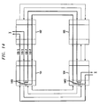
- Fig. 13a shows the signal "X" connection after each body node has received the "loopback complete" message without requiring jumpering at border nodes;
- Fig. 13b shows the signal "X" connection after each body node has received the "loopback complete" message requiring jumpering at border nodes;
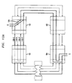
- Fig. 14 shows the signal "X" connection after the border nodes have each propagated a "clear" message through the body nodes; and
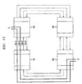
- Fig. 15 shows the signal "X" connection after each border node has received the "clear" message which originated from the other border node, has taken down the loopback connection and restored any provisioned switching connection, and propagates a "takedown" message complete through to the other system body nodes.
- In the following description, each item or block of each figure has a reference designation associated therewith, the first number of which refers to the figure in which that item is first located (e.g., 104 is located in Fig. 1).
- Fig. 1 shows, in simplified form,
BLSR transmission system 100, which for brevity and clarity of exposition is shown as including onlyring nodes 101 through 104, each incorporating an embodiment of the invention. It will be apparent that additional or fewer ring nodes and different orientation of ring nodes may be employed, as desired.Ring nodes 101 through 104 are interconnected bytransmission path 110, including service path 110-S and protection path 110-P, in a counter-clockwise direction, and bytransmission path 120, including service path 120-S and protection path 120-P, in a clockwise direction. In this ex-ample,transmission paths transmission paths ring transmission system 100 could be either a two (2) optical fiber or a four (4) optical fiber system. In a two (2) optical fiber system, each of the fibers intransmission paths transmission paths transmission paths - It is noted that requests and acknowledgments for protection switch action are transmitted in an Automatic Protection Switch (APS) channel in the SDH multiplex section overhead accompanying the protection paths 110-P and 120-P on each of
transmission paths - Each of
ring nodes 101 through 104 comprises an add-drop multiplexer (ADM). Such add-drop multiplexer arrangements are known. For generic requirements of a SDH based ADM see CCITT Recommendation G.782. In this example, the ADM operates in a transmission sense to pass, i.e., express, signals through the ring node, to add signals at the ring node, to drop signals at the ring node, and to bridge and switch signals, in accordance with the principles of the invention, during a protection switch at the ring node. Note that in the event of a loop failure, normal "loopbacks" of the affected signals in ring nodes adjacent to (i.e.,border) the failure occur in a well known manner in these bidirectional multiplex section-switched ring transmission systems. - Fig. 2 shows, in simplified block diagram form, details of
ring nodes 101 through 104. In this example, a clockwise digital signal transmission direction is assumed in the service path 110-S and the protection path 110-P ontransmission path 110. It will be apparent that operation of the ring node and the ADM therein would be similar for a counter-clockwise service path 120-S and the protection path 120-P ontransmission path 120. Specifically, shown are service path 110-S and protection path 110-P entering the ring node and supplying STM-N SDH optical signals to receiver 201-S and receiver 201-P, respectively, where N is, for example, 16. Similarly, shown are service path 120-S and protection path 120-P entering the ring and supplying STM-N SDH optical signals to receiver 202-S and receiver 202-P, respectively, where N is, for example, 16. Details ofreceivers - The SDH STM-N optical signals exit the ring node on service path 110-S as an output from transmitter 203-S, on service path 120-S as an output from transmitter 204-S, on protection path 110-P as an output from transmitter 203-P and on protection path 120-P as an output from transmitter 204-P. Details of
transmitters - AU-4 SDH output signals from receiver 201-S are routed under control of controller 210 either to transmitter 203-S, i.e., expressed through to service path 110-S, to interface 206-S to be dropped, also to interface 206-S for protection switching to interface 206-P where it will be dropped or to transmitter 203-P to be supplied to protection path 110-P. In similar fashion, AU-4 SDH output signals from receiver 202-S are routed under control of controller 210 either to transmitter 204-S, i.e., expressed through to service path 120-S, to interface 207-S to be dropped, also to interface 206-S for protection switching to interface 206-P where it will be dropped or to transmitter 204-P to be supplied to protection path 120-P. (Note that this invention does allow looping back of the AU-4 SDH signals to either protection path 110-P or protection path 120-P, as per conventional BLSR operation.) The AU-4 signals from receiver 201-P are supplied either to transmitter 203-P, i.e., expressed through to protection path 110-P, to interface 206-S to be dropped or to transmitter 203-S to be supplied to service path 110-S. In similar fashion, AU-4 signals from receiver 202-P are routed under control of controller 210 either to transmitter 204-P, i.e., expressed through to protection path 120-P, to interface 207-S to be dropped or to transmitter 204-S to be supplied to service path 120-S. Note that if needed, looping back of the AU-4 SDH signals from service path 110-S to the protection path 110-P occurs using the interfaces 206-S and 206-P. Similarly, looping back of the AU-4 SDH signals from service path 120-S to the protection path 120-P occurs using the interfaces 207-S and 207-P. AU-4 SDH signals being added and dropped via interface 206-S can be bridged to transmitter 203-P and, hence, protection path 110-P and can be switched from receiver 202-P and, hence, from protection path 120-P, all under control of controller 210. Similarly, AU-4 SDH signals being added and dropped via interface 207-S can be bridged to transmitter 204-P and, hence, protection path 120-P and can be switched from receiver 201-P and, hence, from protection path 110-P, all under control of controller 210.
- Interfaces 206-S, 206-P, 207-S and 207-P are employed to interface to particular duplex links 216-S, 216-P, 217-S and 217, respectively, and could include any desired arrangement. For example, interfaces 206 and 207 could include a CEPT-4 digital signal interface to a DSX, a STM-1E (electrical) SDH digital signal interfacing to a DSX, an optical extension interface to an STM-1 SDH optical signal or the like. Such interface arrangements are known.
- In accordance with the present invention, controller 210 uses the program shown in the flow charts of Fig. 10 (which are stored in memory 220) to control the adding, dropping, and bridging of the signals via
interfaces interfaces monitors interfaces - Controller 210 operates to effect the jumpering (signal path to protection path connection), bridging, and switching of communications tributaries at ring nodes, if necessary. Controller 210 communicates with
receivers transmitters interfaces bus 212 with the identities (IDs) of all the communications tributaries passing through the ring node, as well as, those communications tributaries being added and/or dropped at the ring node (stored in tables of Fig. 7 - 9), the identity of all the ring nodes insystem 100 and the positions of the ring nodes in system 100 (stored in Fig. 5). The bridging and switching of communications tributaries under control of controller 210 to effect the invention is described below. - Fig. 3 shows, in simplified form, details of
receivers interface 301, demultiplexer (DEMUX) 302 and driver androuter 303. An STM-N SDH optical signal is supplied to O/E 301 which converts it to an electrical STM-N signal. In turn,DEMUX 302 demultiplexes the STM-N signal, in known fashion, to obtain up to N AUG SDH signal, namely, AUG (1) through AUG (N). Again, in this example, N=16. The AUG (1) through AUG (N) signals are supplied to driver androuter 303 where they are routed under control of controller 210 via the control bus as AU-4 (1) through AU-4 (M) SDH signals. As indicated above, each STM-N signal can include N AUG tributaries, in this example. The AU-4 (1) through AU-4 (M) signals are routed under control of controller 210, as described above regarding Fig. 2.DEMUX 302 also re-moves STM overhead (OH), and supplies the APS channel K bytes to controller 210 via the control bus. - Fig. 4 shows, in simplified form, details of
transmitters select unit 401, multiplexer (MUX) 402 and etectrical/optical interface (E/O) 403. The AU-4 (1) through AU-4 (M) signals are supplied to selectunit 401 where the particular tributaries AUG (1) through AUG (N) are selected under control of controller 210 to be supplied to MUX 402. Again, in this example, N=16. The AUG tributaries are supplied to MUX 402 where overhead (OH) is added to yield an electrical STM-N SDH signal. In turn E/O interface 403 converts the STM-N into an optical STM-N for transmission on the corresponding fiber transmission path. MUX 402 also inserts appropriate K byte messages under control of controller 210 via the control bus. - Fig. 5 shows a ring node map table including the node identification (ID) of and relative location of each of
ring nodes 101 through 104 ofsystem 100. The ring node map table is provisioned via 212 in memory of controller 210. - With reference to Fig. 6 there is shown the format of the switch request message (K1) and switch acknowledgment message (K2). These K byte messages are both generated and monitored by controller 210. The K1 byte indicates a re-quest of a communications tributary for switch action. The first four (4) bits of the K1 byte indicate the switch re-quest priority and the last four (4) bits indicate the ring node identification (ID) of the destination ring node. The K2 byte indicates an acknowledgment of the requested protection switch action. The first four (4) bits of the K2 byte indicate the ring node ID of the source ring node and the last 4 bits indicate the action taken. The first four bits of the K1 bytes are "priority" field which indicated the type of system message, e.g., idle, SF-loop, clear, loopback complete, takedown, etc. The fifth bit of K2 bytes is a long/short bit which indicates the path length. The last three bits of the K2 bytes are called "action taken" field , e.g., idle, FERF (far end remote failure), etc.
- FIGs. 7 - 9 are illustrative node traffic tables for
ring nodes nodes node 104 and is routed vianode 101 and exits atnode 102. The tables of FIGs 7 - 9 include the IDs of active communications tributaries in the clockwise (CW) direction (shown as 701, 801, and 901, respectively) and counter-CW (CCW) direction (shown as 710, 810, and 910, respectively). These tables identify the tributaries (using AU-4#s), the "provisioned" destination paths of those tributaries, and the jumper statuses. Shown in thenode 104 table of Fig. 7 is the AU-4 tributary identification, i.e., X in our example. As previously noted, the number of AU-4 tributaries can be up to 16. As shown in Fig. 1, the X tributary entersnode 104 in the CW direction and exitsnode 101. The provisionedconnection 711 is designated 102 (s7) indicating that CW service channel 7 carries the X signal tonode 102. In node table 102 shown in Fig. 8, the provisionedconnection 811 is designated 104 (s7) indicating that CW service channel 7 carries the X signal fromnode 104. In node table 101 shown in Fig. 9, the provisionedconnection 911 is designated T (S7) indicating that CW service channel 7 carries the X signal in an express manner, i.e., the X signal passes through rather than entering or exiting at this node. As will be discussed in a later paragraph, the X signal path after the transmission path break is shown as 721, 821, 921 in Figs. 7, 8, and 9 , respectively. - Fig. 10 is a flow chart illustrating the operation of controller 210, in accordance with the invention, in controlling the operation of the ring nodes in order to effect the bridging and switching of tributary traffic paths in the presence of a ring impairment or removal of the impairment. A ring impairment is defined as a failure or degradation of the signals from any cause including failure of the transmission paths or of the equipment. It should be noted that all so-called part-time service which was being transported on the protection paths 110-P and 120-P is preempted upon detection of the failure. Thus, the part-time service is taken off of the protection paths 110- P and 120- P.
- At each node, the controller runs the process shown in the flowchart. The controller 210 loops between
steps - At 1005, the controller will take one of three branches depending on whether the new K-byte content indicates one of the following: (1) signal failure/degrade or clear, (2) loopback setup complete, or (3) loopback takedown complete. All other K-byte content changes are handled according to the rules laid down in the BLSR processing document (ITU-T G.841)
- (1) For a signal failure/degrade or clear message, control passes to 1007, where a check is made to see if the jumper flag for that node is set indicating that a jumper already exists. If it does not, then control passes to 1011. If it does, control passes to 1009, where the jumpers are removed, the record of the jumpers is erased, the connections existing prior to the jumpers are re-established, and the jumper flag is reset; control is then passed to 1011.
When control is received at 1011, conventional BLSR processing takes place, Such processing could take various forms depending on the nature of the failure message and the position of the node (i.e., whether it is a border node or a body node). For instance, if the node is a body node, then it will put up a (full or partial, depending on the type of message received) protection pass-through and propagate the message onward; if, on the other hand, it is a border node then it will perform loopback switching and generate a loopback setup complete message in the reverse direction. A key aspect and merit of the invention is that it is impervious to the details of this processing, since by virtue of the previous step, it has undone the jumpering and restored the node to a valid state germane to BLSR operation.
At the completion of the conventional BLSR processing, control is passed to1013, which returns the controller to the wait loop of 1001. - (2) For a loopback setup completion message, control passes to 1015, at which point the controller checks the node traffic pattern to determine if any of the circuits need jumpering. A jumper is needed when the node is an end-point (a node where traffic is added/dropped to/from the ring), unless the ring is segmented by multiple failures and the two end-points are not on the same segment. If the circuits do not need jumpering, then control is transferred to 1019, where conventional BLSR processing takes place. If a circuit needs jumpering, then control is transferred to 1017, where the controller removes the normal circuit connection and establishes the jumpered connection (this consists of disconnecting the dropped channel from the service line and reconnecting it to the same numbered channel on the protection channel coming in from the opposite direction.) When this is complete for all such circuits, a flag is set to indicate that this node is in a jumpered state, and a record of the jumpered connections is made; control is then transferred to 1019, where conventional BLSR processing takes place.
In this case, the conventional processing consists of putting up protection channel pass-throughs for all non-jumpered circuits, and propagating the loopback completion message unless the node happens to be a border node, in which case no further propagation is done.
At the completion of the conventional BLSR processing, control is passed to1013, which returns the controller to the wait loop of 1001. - (3) For a loopback takedown completion message, control passes to 1021, where conventional BLSR processing takes place, which consists of propagating the loopback completion message unless the node happens to be a border node, in which case no further propagation is done.
- At the completion of the conventional BLSR processing, control is passed to1013, which returns the controller to the wait loop of 1001.
- This last case is actually the same as case (1), since the step involving the jumpered circuits is a null step, for no jumpers can exist at this point. However, it has been explicitly culled out to make it symmetrical with step (2).
- Figs. 11 through 16 provide an illustration of the operation of the present invention for a single failure occurring within a normally operating ring, and will make reference to Figs. 7 through 10. The following description assumes that an X signal tributary connection has been established, in a well known manner, to enter
node 104 and traversenode 101 and exit atnode 102, as is shown in Fig. 11. The node tables fornodes - In Fig. 12a, a complete fiber cut fault has occurred between
nodes Nodes border nodes node 101 is sending tonode 102 andnode 104 to node 103). Note the following description traces the function performed at the different nodes (1) as the messages that originated atnode 101 are propagated throughnodes node 104 are propagated throughnodes - When the failure message is received at
node 102, the controller, having detected a change in the K-bytes, ceases looping at 1003, checks the message at 1005, and proceeds to step 1007, where it checks the jumper flag. In this example, we are assuming that the ring was unimpaired prior to the fiber cut fault, hence the jumper flag is not set, and therefore, control passes directly to step 1011. Normal BLSR processing is performed which consists of putting up a protection pass through 1201, which allows onward propagation of the K-bytes tonode 103. - At
node 103, similar events take place as atnode 102, resulting in a protection pass through 1202, and the K-bytes propagating on tonode 104. Note that this passthrough may already have been set up due to the receipt of K-bytes fromnode 104, which is closer. Again, all this is as per normal BLSR processing. - Referring now to Fig. 12b, the receipt of the K-bytes at
node 104 causes its controller to pass to step 1005. There are no jumpers, so control passes on to 1011 and normal BLSR operation takes place - in this case this comprises the setting up ofsignal loopback 1203. - Meanwhile, the K-byte messages originating at
node 104 and propagating throughnodes 103 and 101 (in like fashion to the above) result in the setting up ofsignal loopback 1204 atnode 101. - Thus Fig. 12b shows the signal "X"
connection 1205 after eachborder node - In accordance with normal BLSR processing in
step 1011, the controllers ofborder nodes step 1013, to looping at steps 1001-1003. - At
node 102, the "loopback complete" message fromnode 101 is received before the one fromnode 104 arrives,step 1014 is performed, and control is transferred to normal BLSR processing instep 1019, which does nothing further than pass on the "loopback complete" K-bytes. - When the "loopback complete" message from
node 104 is received atnode 102, it performsstep 1014 and proceeds on to step 1015, since the other loopback complete message (i.e., the one from node 101) has already been received. Instep 1015, a jumper is needed, since the X signal tributary will need to be received from (and transmitted to) the right-hand side in order to eliminate the loop formed to the left.Step 1017 causesnode 102 to remove provisionedconnection 1205 andpassthrough connection 1206 of Fig. 12b, and put in jumpers (1301 of Figs. 13a and 13b), and set the jumper flag (column 804 ofrow 821 of Fig. 8). Note that the record of the originally provisioned connection is maintained in the node's memory (column 803 of Fig. 8) for subsequent restoral. -
Node 102 then propagates the loopback completion message CCW tonode 101, where per normal BLSR operation, steady state is reached. Control at 102 also returns to steady state (looping at 1001-1003) viastep 1013. - Note that it is not necessary to put up jumpers at
node 104 since it will have the same effect as the loopback at that node (there being no extended loop to truncate), and the present invention does not call for such jumpers to be put up. However, optionally, one may indeed put up such jumpers (Figure 13b) if that is more desirable. - At this point in time, the system routing connection of the X signal, appears as shown in Fig. 13. As shown in Fig. 13, the resulting restored path is shorter for signal X.
- The controller at all of the nodes cycles through
steps border nodes node node 102 receives the clear message from 101, control is transferred to step 1007 where the jumper flag is checked; since the flag is set indicating that a jumper exists at node 102 (seecolumn 804 and row 821 of Fig. 8) the controller performsstep 1009, and (1) the jumpered connection is taken down, (2) normal (i.e., provisioned) circuit connections restored, and (3) the jumper flag reset. Control then moves to step 1011, whereupon normal BLSR processing is performed, which in this case means that the nodes propagates the clear message to the next node, 103. Control atnode 102 then passes to step 1013 and to step 1001. - The clear message is similarly processed in
node 103, where it is merely passed through since there are no jumpers set at that node. - With regard to the clear message sent from 104 to 103, since there are no jumpers at 103, no special actions take place there other than normal BLSR processing (the message merely gets propagated), and likewise at 102. At this time the routing of the X signal and other node connections appears as shown in Fig. 14, where the signals are flowing through the conventional BLSR loopback connections and not through the jumpered paths.
- When the clear message originated at 101
reaches node 104, since no jumper flag is set, control passes to step 1011 and it executes normal BLSR procedure, whereby theloopback connection 1401 is taken down. Per BLSR procedure, a takedown confirmation message is then sent fromnode 104. Control then passes to step 1017 and then to step 1001. - Likewise, the clear message sent from 104 results in
loopback connection 1402 to be taken down and a takedown confirmation message to be sent fromnode 101. - At this time the routing of the X signal and other node connections appears as shown in Fig. 15, which is the normal provisioned state.
- The takedown confirmation messages from
node 104 is propagated back throughnodes node 101 is propagated back throughnodes step 1021 in Fig. 10, and stable operation is reached. - While we have described the operation of the present invention for a single signal tributary X, it should be noted that our invention can process multiple signal tributaries entering and exiting from different nodes at the same or different times. Thus, our single tributary operational description was merely illustrative of the operation of the present invention. Additionally, the above-described circuits and arrangements are, of course, merely illustrative of the application of the principles of the invention.
Claims (12)
- A communication node (Fig. 2) for use in a bidirectional multiplex section-switched ring transmission system (Fig. 1) including a plurality of nodes (101-104) and a first (110) and second (120) transmission paths, each transmission path including a service path and a protection path interconnecting said plurality of nodes and transporting communications signals around said system from node to node in a different transmission direction, said node detecting a trouble in the transmission path and rerouting a connection around the troubled transmission path, said node CHARACTERIZED BY:memory (202) for storing entries identifying all the nodes and their relative positions in said system, and for storing entries for each of the communication tributaries active at a node which includes entries identifying its provisioned service connection path and a jumper flag (804) indicating if a jumpered connection (1301) path exists;programmable controller (200) for accessing and updating entries in said memory and for controlling communication tributaries and including;determining means (1015) responsive to a loopback setup complete message received at a node from both the first and second directions for determining if a jumpered connection is needed at that node;jumper connection means (1017) for establishing a jumpered connection if said determining means indicates a jumpered connection is needed, the jumper connection established by taking down the provisioned connection, putting up the jumpered connection and setting a jumper flag; and enabling said conventional BLSR processing means to perform BLSR processingBLSR processing means (1019) for performing BLSR processing if said determining means indicates a juinpered connection is not needed or after said jumpers connection means (1017) has established the jumpered connection.
- The node of claim 1 wherein in response to a loopback takedown message received at this node from both the first and second directions, conventional BLSR processing is performed.
- The node of claim 1 wherein
in response to a signal fail/degrade message received at this node from both the first and second directions it is determined if a jumper flag is to be set at that node,
if the jumper flag is set, the jumpered connection is taken down, the provisioned connection restored, and the jumper flag reset, and
if the jumper flag, is not set, conventional BLSR processing is performed. - The node of any of claims 1 to 3 wherein
in response to a clear message received at this node from both the first and second directions it is determined if a jumper flag is set at that node,
if the jumper flag is set, the jumpered connection is taken down, the provisioned connection restored, and the jumper flag reset, and
if the jumper flag is not set, conventional BLSR processing is performed. - The node of claim 1 wherein said message includes K-bytes.
- A bidirectional multiplex section-switched ring transmission system (Fig. 1) including said plurality of nodes (101-104), each node being the node of claim 1.
- The system of claim 6 wherein said jumpered connection is needed only at nodes at which traffic is being added or dropped from the first or second transmission paths.
- A method of operating a node (Fig. 2) of a bidirectional multiplex section-switched ring transmission system (100) including a plurality of nodes (101-104) and a first (110) and second (120) transmission paths, each transmission path including a service path and a protection path interconnecting said plurality of nodes and transporting communications signals around said system from node to node in a different transmission direction, said node detecting a trouble in the transmission path and rerouting a connection around the troubled transmission path, the method CHARACTERIZED BY the steps of :A. storing entries identifying all the nodes and their relative positions in said system;B. storing entries for each of the communication tributaries active at a node which includes entries identifying its provisioned service connection path, its jumpered connection (1301) path, and a jumper flag indicating if a jumpered connection path exists;C. in response to a loopback setup complete message received at a node from both the first and second directions, determining if a jumpered connection is needed at this node,C1. if a jumpered connection is not needed, performing conventional BLSR processing,C2. if a jumpered connection is needed, taking down the provisioned connection, putting up the jumpered connection, setting a jumper flag, and performing conventional BLSR processing.
- The method of claim 8 further including the step of:in response to a loopback takedown message received at this node from both the first and second directions, performing conventional BLSR processing.
- The method of any one of claims 8 or 9 further including the steps of:in response to a signal fail/degrade message received at this node from both the first and second directions, determining if a jumper flag is set at that node,if the jumper flag is set taking the jumpered connection down, restoring the provisioned connection, and resetting the jumper flag andif the jumper flag is not set, performing conventional BLSR processing.
- The method of any one of claims 8, 9, or 10 further including the step of :in response to a signal fail/degrade clear message received at this node from both the first and second directions, determining if a jumper flag is set at that node,if the jumper flag is set taking the jumpered connection down, restoring the provisioned connection, and resetting the jumper flag andif the jumper flag is not set, performing conventional BLSR processing.
- The method of claim 8 being performed at a plurality of nodes of said bidirectional multiplex section-switched ring transmission system.
Applications Claiming Priority (2)
| Application Number | Priority Date | Filing Date | Title |
|---|---|---|---|
| US09/146,209 US6246667B1 (en) | 1998-09-02 | 1998-09-02 | Backwards-compatible failure restoration in bidirectional multiplex section-switched ring transmission systems |
| US146209 | 1998-09-02 |
Publications (3)
| Publication Number | Publication Date |
|---|---|
| EP0984574A2 EP0984574A2 (en) | 2000-03-08 |
| EP0984574A3 EP0984574A3 (en) | 2003-12-03 |
| EP0984574B1 true EP0984574B1 (en) | 2007-03-21 |
Family
ID=22516296
Family Applications (1)
| Application Number | Title | Priority Date | Filing Date |
|---|---|---|---|
| EP99306650A Expired - Lifetime EP0984574B1 (en) | 1998-09-02 | 1999-08-23 | Backwards-compatible failure restoration in bidirectional multiplex section-switched ring transmission systems |
Country Status (6)
| Country | Link |
|---|---|
| US (1) | US6246667B1 (en) |
| EP (1) | EP0984574B1 (en) |
| JP (1) | JP3390705B2 (en) |
| AU (1) | AU4588299A (en) |
| CA (1) | CA2278828C (en) |
| DE (1) | DE69935560T2 (en) |
Families Citing this family (33)
| Publication number | Priority date | Publication date | Assignee | Title |
|---|---|---|---|---|
| JP3175826B2 (en) * | 1998-11-24 | 2001-06-11 | 日本電気株式会社 | Network configuration method and network management node |
| US6973267B1 (en) * | 1999-07-01 | 2005-12-06 | Cisco Technology, Inc. | Autoprotected optical communication ring network |
| EP1096712A3 (en) * | 1999-10-29 | 2005-09-07 | Nippon Telegraph and Telephone Corporation | Path network and path network operation method using conversion of protection path into working path |
| IT1316316B1 (en) * | 2000-02-01 | 2003-04-10 | Cit Alcatel | TRAFFIC PROTECTION METHOD IN FIBER OPTIC TRANSPORT NETWORKS IN WDM TECHNOLOGY |
| US6920113B1 (en) * | 2000-03-28 | 2005-07-19 | Telsima Inc. | Transport of iscochronous and bursty data on a sonet ring |
| US7085293B2 (en) | 2000-03-28 | 2006-08-01 | Telsima Inc. | Scaleable transport of TDM channels in a synchronous frame |
| EP1161014A1 (en) * | 2000-05-31 | 2001-12-05 | PIRELLI CAVI E SISTEMI S.p.A. | Autoprotected optical communication ring network |
| US6965572B1 (en) * | 2000-06-07 | 2005-11-15 | At&T Corp. | Loopback capability for bi-directional multi-protocol label switching traffic engineered trucks |
| US20020059408A1 (en) * | 2000-11-02 | 2002-05-16 | Krishna Pattabhiraman | Dynamic traffic management on a shared medium |
| US20030031126A1 (en) * | 2001-03-12 | 2003-02-13 | Mayweather Derek T. | Bandwidth reservation reuse in dynamically allocated ring protection and restoration technique |
| US6892329B2 (en) * | 2001-04-02 | 2005-05-10 | Corrigent Systems Ltd. | Selective protection for ring topologies |
| US7054264B2 (en) * | 2001-07-24 | 2006-05-30 | Corrigent Systems Ltd. | Interconnect and gateway protection in bidirectional ring networks |
| US7061859B2 (en) | 2001-08-30 | 2006-06-13 | Corrigent Systems Ltd. | Fast protection in ring topologies |
| US6766482B1 (en) | 2001-10-31 | 2004-07-20 | Extreme Networks | Ethernet automatic protection switching |
| US6917986B2 (en) * | 2002-01-07 | 2005-07-12 | Corrigent Systems Ltd. | Fast failure protection using redundant network edge ports |
| US6778492B2 (en) * | 2002-01-17 | 2004-08-17 | Cisco Technology, Inc. | Load balancing for fast reroute backup tunnels |
| US7158721B2 (en) * | 2002-02-25 | 2007-01-02 | Corrigent Systems Ltd. | Performance monitoring of multiple channels in an automatic protection switched network |
| US7151742B1 (en) * | 2002-03-08 | 2006-12-19 | Mindspeed Technologies, Inc. | Flow control for communication ring access control |
| US6801865B2 (en) * | 2002-03-21 | 2004-10-05 | Engage Networks, Inc. | Meter monitoring and tamper protection system and method |
| US7433593B1 (en) * | 2002-06-28 | 2008-10-07 | Ciena Corporation | Switching algorithm for optical fiber networks |
| US7032135B2 (en) * | 2002-08-02 | 2006-04-18 | Corrigent Systems Ltd. | Equipment protection using a partial star architecture |
| US7418493B1 (en) | 2002-09-30 | 2008-08-26 | Cisco Technology, Inc. | Method for computing FRR backup tunnels using aggregate bandwidth constraints |
| US7848249B1 (en) | 2002-09-30 | 2010-12-07 | Cisco Technology, Inc. | Method for computing FRR backup tunnels using aggregate bandwidth constraints |
| US20050058060A1 (en) * | 2003-09-16 | 2005-03-17 | Nortel Networks Limited | K-byte extension and tunnel identifying scheme for tunnel-based shared mesh protection |
| US7974223B2 (en) * | 2004-11-19 | 2011-07-05 | Corrigent Systems Ltd. | Virtual private LAN service over ring networks |
| US7402520B2 (en) * | 2004-11-26 | 2008-07-22 | Applied Materials, Inc. | Edge removal of silicon-on-insulator transfer wafer |
| US7983150B2 (en) * | 2006-01-18 | 2011-07-19 | Corrigent Systems Ltd. | VPLS failure protection in ring networks |
| US7808931B2 (en) * | 2006-03-02 | 2010-10-05 | Corrigent Systems Ltd. | High capacity ring communication network |
| US7593400B2 (en) * | 2006-05-19 | 2009-09-22 | Corrigent Systems Ltd. | MAC address learning in a distributed bridge |
| US7660303B2 (en) | 2006-08-22 | 2010-02-09 | Corrigent Systems Ltd. | Point-to-multipoint functionality in a bridged network |
| US7660234B2 (en) * | 2006-09-22 | 2010-02-09 | Corrigent Systems Ltd. | Fault-tolerant medium access control (MAC) address assignment in network elements |
| JP4866942B2 (en) * | 2009-07-09 | 2012-02-01 | 富士通テレコムネットワークス株式会社 | Transmission device, transmission control method, and OSC processing device |
| CN101998186A (en) * | 2009-08-13 | 2011-03-30 | 中兴通讯股份有限公司 | Network protection method and device |
Family Cites Families (7)
| Publication number | Priority date | Publication date | Assignee | Title |
|---|---|---|---|---|
| US5341364A (en) | 1992-06-02 | 1994-08-23 | At&T Bell Laboratories | Distributed switching in bidirectional multiplex section-switched ringtransmission systems |
| US5442623A (en) * | 1992-08-17 | 1995-08-15 | Bell Communications Research, Inc. | Passive protected self healing ring network |
| JPH0795225A (en) * | 1993-09-20 | 1995-04-07 | Fujitsu Ltd | Bidirectional ring network control system |
| JPH07264228A (en) * | 1994-03-17 | 1995-10-13 | Fujitsu Ltd | Blsr network with path ais generating function |
| JPH0897841A (en) * | 1994-09-29 | 1996-04-12 | Hitachi Ltd | Method for controlling path changeover transmitter and the path changeover transmitter |
| JP2630283B2 (en) * | 1994-12-21 | 1997-07-16 | 日本電気株式会社 | Orderwire communication control method for ring network system |
| JP2677244B2 (en) * | 1995-05-10 | 1997-11-17 | 日本電気株式会社 | Protection control signal transmission system |
-
1998
- 1998-09-02 US US09/146,209 patent/US6246667B1/en not_active Expired - Lifetime
-
1999
- 1999-07-26 CA CA002278828A patent/CA2278828C/en not_active Expired - Fee Related
- 1999-08-23 DE DE69935560T patent/DE69935560T2/en not_active Expired - Lifetime
- 1999-08-23 EP EP99306650A patent/EP0984574B1/en not_active Expired - Lifetime
- 1999-09-01 AU AU45882/99A patent/AU4588299A/en not_active Abandoned
- 1999-09-02 JP JP24811999A patent/JP3390705B2/en not_active Expired - Fee Related
Also Published As
| Publication number | Publication date |
|---|---|
| AU4588299A (en) | 2000-03-16 |
| DE69935560D1 (en) | 2007-05-03 |
| JP3390705B2 (en) | 2003-03-31 |
| US6246667B1 (en) | 2001-06-12 |
| DE69935560T2 (en) | 2007-12-06 |
| EP0984574A2 (en) | 2000-03-08 |
| EP0984574A3 (en) | 2003-12-03 |
| CA2278828C (en) | 2003-01-28 |
| CA2278828A1 (en) | 2000-03-02 |
| JP2000165427A (en) | 2000-06-16 |
Similar Documents
| Publication | Publication Date | Title |
|---|---|---|
| EP0984574B1 (en) | Backwards-compatible failure restoration in bidirectional multiplex section-switched ring transmission systems | |
| EP0573211B1 (en) | Distributed switching in bidirectional multiplex section-switched ring transmission systems | |
| EP0590872B1 (en) | Apparatus and method for selectively tributary switching in a bidirectional ring transmission system | |
| US5442620A (en) | Apparatus and method for preventing communications circuit misconnections in a bidirectional line-switched ring transmission system | |
| US5278824A (en) | Dual hubbing in a bidirectional line-switched ring transmission system | |
| US5440540A (en) | Ring interworking between a bidirectional line-switched ring transmission system and another ring transmission system | |
| CA2337352C (en) | Method and apparatus for signaling path restoration information in a mesh network | |
| US8116196B2 (en) | Shared mesh signaling method and apparatus | |
| EP0745294B1 (en) | Telecommunications network including a channel switching protection arrangement | |
| US6757306B1 (en) | Method and system for intermediate system level 2 transparency using the SONET LDCC | |
| EP0994635B1 (en) | Method and apparatus for data transmission in synchronous optical networks | |
| JPH07212382A (en) | Communication system | |
| JP2001016240A (en) | Optical ring network | |
| EP1217789B1 (en) | Self-relief method and re-estabishing method for traffic | |
| JP3226773B2 (en) | Method for use in a predetermined ring node of a plurality of ring nodes and method for deterministically squelching a communication circuit in a ring node transmission system |
Legal Events
| Date | Code | Title | Description |
|---|---|---|---|
| PUAI | Public reference made under article 153(3) epc to a published international application that has entered the european phase |
Free format text: ORIGINAL CODE: 0009012 |
|
| AK | Designated contracting states |
Kind code of ref document: A2 Designated state(s): AT BE CH CY DE DK ES FI FR GB GR IE IT LI LU MC NL PT SE |
|
| AX | Request for extension of the european patent |
Free format text: AL;LT;LV;MK;RO;SI |
|
| PUAL | Search report despatched |
Free format text: ORIGINAL CODE: 0009013 |
|
| AK | Designated contracting states |
Kind code of ref document: A3 Designated state(s): AT BE CH CY DE DK ES FI FR GB GR IE IT LI LU MC NL PT SE |
|
| AX | Request for extension of the european patent |
Extension state: AL LT LV MK RO SI |
|
| 17P | Request for examination filed |
Effective date: 20040522 |
|
| AKX | Designation fees paid |
Designated state(s): DE FR GB |
|
| GRAP | Despatch of communication of intention to grant a patent |
Free format text: ORIGINAL CODE: EPIDOSNIGR1 |
|
| GRAS | Grant fee paid |
Free format text: ORIGINAL CODE: EPIDOSNIGR3 |
|
| GRAA | (expected) grant |
Free format text: ORIGINAL CODE: 0009210 |
|
| AK | Designated contracting states |
Kind code of ref document: B1 Designated state(s): DE FR GB |
|
| REG | Reference to a national code |
Ref country code: GB Ref legal event code: FG4D |
|
| REF | Corresponds to: |
Ref document number: 69935560 Country of ref document: DE Date of ref document: 20070503 Kind code of ref document: P |
|
| ET | Fr: translation filed | ||
| PLBE | No opposition filed within time limit |
Free format text: ORIGINAL CODE: 0009261 |
|
| STAA | Information on the status of an ep patent application or granted ep patent |
Free format text: STATUS: NO OPPOSITION FILED WITHIN TIME LIMIT |
|
| 26N | No opposition filed |
Effective date: 20071227 |
|
| REG | Reference to a national code |
Ref country code: GB Ref legal event code: 732E Free format text: REGISTERED BETWEEN 20131031 AND 20131106 |
|
| REG | Reference to a national code |
Ref country code: FR Ref legal event code: CD Owner name: ALCATEL-LUCENT USA INC. Effective date: 20131122 |
|
| REG | Reference to a national code |
Ref country code: FR Ref legal event code: GC Effective date: 20140410 |
|
| REG | Reference to a national code |
Ref country code: FR Ref legal event code: RG Effective date: 20141015 |
|
| REG | Reference to a national code |
Ref country code: FR Ref legal event code: PLFP Year of fee payment: 17 |
|
| REG | Reference to a national code |
Ref country code: FR Ref legal event code: PLFP Year of fee payment: 18 |
|
| PGFP | Annual fee paid to national office [announced via postgrant information from national office to epo] |
Ref country code: GB Payment date: 20160819 Year of fee payment: 18 Ref country code: DE Payment date: 20160822 Year of fee payment: 18 |
|
| PGFP | Annual fee paid to national office [announced via postgrant information from national office to epo] |
Ref country code: FR Payment date: 20160822 Year of fee payment: 18 |
|
| REG | Reference to a national code |
Ref country code: DE Ref legal event code: R119 Ref document number: 69935560 Country of ref document: DE |
|
| GBPC | Gb: european patent ceased through non-payment of renewal fee |
Effective date: 20170823 |
|
| REG | Reference to a national code |
Ref country code: FR Ref legal event code: ST Effective date: 20180430 |
|
| PG25 | Lapsed in a contracting state [announced via postgrant information from national office to epo] |
Ref country code: DE Free format text: LAPSE BECAUSE OF NON-PAYMENT OF DUE FEES Effective date: 20180301 Ref country code: GB Free format text: LAPSE BECAUSE OF NON-PAYMENT OF DUE FEES Effective date: 20170823 |
|
| PG25 | Lapsed in a contracting state [announced via postgrant information from national office to epo] |
Ref country code: FR Free format text: LAPSE BECAUSE OF NON-PAYMENT OF DUE FEES Effective date: 20170831 |