US6257983B1 - Computer readable program product storing program for cursor display in ball-playing game, said program, and cursor display processing apparatus and method for ball-playing type game - Google Patents
Computer readable program product storing program for cursor display in ball-playing game, said program, and cursor display processing apparatus and method for ball-playing type game Download PDFInfo
- Publication number
- US6257983B1 US6257983B1 US09/633,150 US63315000A US6257983B1 US 6257983 B1 US6257983 B1 US 6257983B1 US 63315000 A US63315000 A US 63315000A US 6257983 B1 US6257983 B1 US 6257983B1
- Authority
- US
- United States
- Prior art keywords
- ball
- cursor display
- tilt
- cursor
- set forth
- Prior art date
- Legal status (The legal status is an assumption and is not a legal conclusion. Google has not performed a legal analysis and makes no representation as to the accuracy of the status listed.)
- Expired - Lifetime
Links
Images


Classifications
-
- G—PHYSICS
- G06—COMPUTING; CALCULATING OR COUNTING
- G06F—ELECTRIC DIGITAL DATA PROCESSING
- G06F3/00—Input arrangements for transferring data to be processed into a form capable of being handled by the computer; Output arrangements for transferring data from processing unit to output unit, e.g. interface arrangements
- G06F3/01—Input arrangements or combined input and output arrangements for interaction between user and computer
- G06F3/03—Arrangements for converting the position or the displacement of a member into a coded form
- G06F3/033—Pointing devices displaced or positioned by the user, e.g. mice, trackballs, pens or joysticks; Accessories therefor
- G06F3/038—Control and interface arrangements therefor, e.g. drivers or device-embedded control circuitry
-
- A—HUMAN NECESSITIES
- A63—SPORTS; GAMES; AMUSEMENTS
- A63F—CARD, BOARD, OR ROULETTE GAMES; INDOOR GAMES USING SMALL MOVING PLAYING BODIES; VIDEO GAMES; GAMES NOT OTHERWISE PROVIDED FOR
- A63F2300/00—Features of games using an electronically generated display having two or more dimensions, e.g. on a television screen, showing representations related to the game
- A63F2300/60—Methods for processing data by generating or executing the game program
- A63F2300/6045—Methods for processing data by generating or executing the game program for mapping control signals received from the input arrangement into game commands
-
- A—HUMAN NECESSITIES
- A63—SPORTS; GAMES; AMUSEMENTS
- A63F—CARD, BOARD, OR ROULETTE GAMES; INDOOR GAMES USING SMALL MOVING PLAYING BODIES; VIDEO GAMES; GAMES NOT OTHERWISE PROVIDED FOR
- A63F2300/00—Features of games using an electronically generated display having two or more dimensions, e.g. on a television screen, showing representations related to the game
- A63F2300/80—Features of games using an electronically generated display having two or more dimensions, e.g. on a television screen, showing representations related to the game specially adapted for executing a specific type of game
- A63F2300/8011—Ball
-
- G—PHYSICS
- G06—COMPUTING; CALCULATING OR COUNTING
- G06F—ELECTRIC DIGITAL DATA PROCESSING
- G06F2203/00—Indexing scheme relating to G06F3/00 - G06F3/048
- G06F2203/038—Indexing scheme relating to G06F3/038
- G06F2203/0382—Plural input, i.e. interface arrangements in which a plurality of input device of the same type are in communication with a PC
Definitions
- the present invention relates to a computer readable program product storing a program for processing of a cursor display of a ball-playing type game using a joystick or other control device, such a program, and a ball-playing type game processor and method.
- control units control panels, keypads, etc.
- game machines PlayStation (made by Sony Computer Entertainment), Dreamcast (made by Sega Enterprise), etc.)
- the control unit is in general comprised of a plurality of keys (or buttons) or a joystick. Whether a sports type game or a role-playing game, a control system comprised of a limited number of buttons and number of joysticks on a control unit is incorporated. Of course, a game can be played on even a personal computer. If using a keyboard, keys necessary for control of the game are assigned from the keyboard.
- a cursor is displayed inside a strike zone displayed on the screen or near it for designating the position of the thrown ball (hereinafter referred to as the “ball position”).
- This cursor is often displayed in the shape of a circle. The user can operate the joystick to make the cursor move on the display screen and designate any ball position.
- the strike zone includes portions where the ball position has to be accurately designated and portions where accurate designation is unnecessary.
- the ball zone sometimes is hard to hit solidly even if the batter were to swing. In such a case, for the user controlling the pitcher to prevent easy hits by the batter, it was necessary to accurately designate the ball position near the boundary between the strike zone and the ball zone.
- the general practice for the batter is to swing at the center portion of the zone rather than swing near the boundary between the zone and outside the zone.
- An object of the present invention is to provide a computer readable program product storing a program for processing of the cursor display of a ball-playing game enabling fine adjustment of the cursor display in the strike zone or batting zone in accordance with the desire of the user by an approach different from the above publication, such a program, and a cursor display processor and method for a ball-playing type game.
- a computer readable program product storing a program for processing of a cursor display in a ball-playing type game, the program product storing a program for making a computer receive as input tilt data output in accordance with operation by a user using a control device outputting tilt data expressing a tilt angle and tilt direction, calculate coordinate data based on the input tilt data using a first function linked with a first axial direction and a second function different from the first function and linked with a second axial direction for two intersecting axes when converting the input tilt data to two-dimensional coordinates, and process movement of the cursor display based on the calculated coordinate data.
- a program for processing a cursor display of a ball-playing type game making a computer receive as input tilt data output in accordance with operation by a user using a control device outputting tilt data expressing a tilt angle and tilt direction, calculate coordinate data based on the input tilt data using a first function linked with a first axial direction and a second function different from the first function and linked with a second axial direction for two intersecting axes when converting the input tilt data to two-dimensional coordinates, and process movement of the cursor display based on the calculated coordinate data.
- a cursor display processor for a ball-playing type game comprising a computer readable program product storing a program for processing of a cursor display of a ball-playing type game, a computer for reading and executing at least part of the program from the program product, and a display for displaying the ball-playing type game realized by the computer, the computer receiving as input tilt data output in accordance with operation by a user using a control device outputting tilt data expressing a tilt angle and tilt direction, calculating coordinate data based on the input tilt data using a first function linked with a first axial direction and a second function different from the first function and linked with a second axial direction for two intersecting axes when converting the input tilt data to two-dimensional coordinates, and displaying movement of the cursor display on the display based on the calculated coordinate data.
- a cursor display processing method for a ball-playing type game for processing of a cursor display of a ball-playing type game comprising receiving as input tilt data output in accordance with operation by a user using a control device outputting tilt data expressing a tilt angle and tilt direction, calculating coordinate data based on the input tilt data using a first function linked with a first axial direction and a second function different from the first function and linked with a second axial direction for two intersecting axes when converting the input tilt data to two-dimensional coordinates, and processing movement of the cursor display on the display based on the calculated coordinate data.
- the range of movement of the cursor display may be within a rectangular shape including a strike zone.
- the first and second functions may be functions expressing curves having tilt data as variables or may use sines.
- the range of movement of the cursor display may be within a rectangular shape forming a batting zone.
- the first and second functions may be functions expressing curves having tilt data as variables or includes a sine.
- FIG. 1 is a block diagram of an example of the hardware configuration of an embodiment of the present invention
- FIG. 2 is a view of the relationship between a tilt angle of a joystick and tilt data, according to an embodiment of the present invention
- FIG. 3 is a view of a coordinate system of a plane including a strike zone, according to an embodiment of the present invention.
- FIG. 4A shows the change in state of the joystick
- FIG. 4B shows the tilt data in the x-axial direction in accordance with the state of the joystick
- FIG. 4C shows the displacement in the X-axial direction of the target position of movement obtained in accordance with the tilt data, according to an embodiment of the present invention
- FIG. 5 is a view of an example of a function Fh(x) for designating the position of the cursor
- FIG. 6A is a first view schematically showing the state of movement of the cursor
- FIG. 6B is a second view schematically showing the state of movement of the cursor
- FIG. 6C is a second view schematically showing the state of movement of the cursor.
- FIG. 6D is a second view schematically showing the state of movement of the cursor, according to an embodiment of the present invention.
- FIG. 7 is a view of an example of a function Gh(x) for designating the position of the cursor
- FIG. 8A is a first view schematically showing the state of movement of a batting cursor
- FIG. 8B is a second view schematically showing the state of movement of the batting cursor, according to an embodiment of the present invention.
- FIG. 9 is a first view of an example of the change of state of the display image in the case of displaying a game image from a perspective behind the catcher;
- FIG. 10 is a second view of an example of the change of state of the display image in the case of displaying a game image from a perspective behind the catcher;
- FIG. 11 is a third view of an example of the change of state of the display image in the case of displaying a game image from a perspective behind the catcher;
- FIG. 12 is a flow chart of the routine of pitching processing, according to an embodiment of the present invention.
- FIG. 13 is a flow chart of the routine of batting processing, according to an embodiment of the present invention.
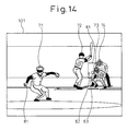
- FIG. 14 is a first view of an example of the change of state of the display image in the case of displaying a game image from a perspective behind the pitcher;
- FIG. 15 is a second view of an example of the change of state of the display image in the case of displaying a game image from a perspective behind the pitcher.
- FIG. 16 is a view of an example of the display image in the case of displaying an image from a plurality of perspectives.
- FIG. 1 shows an example of the configuration of a video game system according to an embodiment of the present invention.
- the video game system 10 shown in FIG. 1 is provided with the functions of a ball-playing type game processor according to an embodiment of the present invention. Further, the video game system 10 executes a program stored on a computer readable program product according to an embodiment of the present invention. Further, the video game system 10 is used for working the ball-playing type game processing method according to an embodiment of the present invention.
- the video game system 10 includes, for example, a game console 11 for processing a video game in accordance with a program, a keypad 50 for interactively controlling the video game, and a television set (hereinafter called a “TV set”) having a cathode ray tube (CRT) etc. as a monitor with speakers. Further, this video game system 10 is provided with a communications interface unit 21 and is connected to a network 111 by a communications line 110 for data communications with another network apparatus.
- a game console 11 for processing a video game in accordance with a program
- a keypad 50 for interactively controlling the video game
- TV set television set having a cathode ray tube (CRT) etc.
- this video game system 10 is provided with a communications interface unit 21 and is connected to a network 111 by a communications line 110 for data communications with another network apparatus.
- a keypad 50 has a group of buttons 50 a , 50 b , 50 c , 50 d , etc. or a joystick 50 e able to be operated by the user (operator). Instructions due to the button operation or joystick operation of the user are given to the game console 11 .
- a keypad 51 further has for example the group of buttons 51 a , 51 b , 51 c , 51 d , etc. or the joystick 51 e operable by the user.
- buttons or joystick have the functions of inputting a pitching operation of the pitcher, a swinging operation of the batter, a stealing operation of a runner, and a catching/throwing operation of a fielder in the operation of a baseball game explained later.
- the joysticks 50 e , 51 e have the function of designating the position of the cursor showing the ball position of the pitcher in the strike zone of the screen or around it and the position of the cursor showing the batting position of the batter (position through which the bat passes due to a swing) in the batting zone.
- the TV set 100 displays a video (image) or outputs sound in accordance with the content of the game based on a video signal and sound signal output from the game console 11 .
- the game console 11 has an internal bus 25 .
- the internal bus 25 has connected to it a controller provided with a central processing unit (CPU), read only memory (ROM), and other units, a random access memory (RAM) 13 , and a hard disk drive (HDD) 14 .
- CPU central processing unit
- ROM read only memory
- RAM random access memory
- HDD hard disk drive
- the controller 12 controls the hardware as a whole and stores all or part of the program in the RAM 13 for execution of the game processing.
- the RAM 13 is provided with a program area 13 A, an image data area 13 B, a work area 13 C, etc.
- the program area 13 A stores the program of the game. Specifically, the program area 13 A stores all or part of the game program read by the CD-ROM drive 20 from the CD-ROM 19 .
- the image data area 13 B stores image data such as the background or game characters required in the process of execution of the program.
- the work area 13 C stores various types of data generated in the process of execution of the program.
- the game program 15 and image data can be supplied from an HDD 14 other than a CD-ROM 19 .
- the game program 15 or image data may be stored in a storage medium (hard disk) of the HDD 14 .
- the hard disk may store the game program or image data installed in advance or downloaded through the communications line 110 from the network 111 .
- the internal bus 25 has connected to it an input interface unit 24 , a sound processor 18 , and a graphics processor 16 .
- the keypads 50 , 51 are connected through the input interface unit 24 to the internal bus 25 .
- the TV set 100 connects the sound processor 18 and graphics processor 16 through it to the internal bus 25 .
- the graphics processor 16 is provided with a video random access memory (VRAM) 17 having a frame buffer.
- VRAM video random access memory
- the graphics processor 16 generates a video signal based on the image data stored in the frame buffer by instructions from the controller 12 along with execution of the program and outputs the video signal to the TV set 100 . Due to this, an image is displayed on the display screen 101 of the TV set 100 by the image data stored in the frame buffer.
- the sound processor 18 generates a sound signal expressing voices, background music (BGM), sound effects, etc. in accordance with the instruction from the controller 12 and outputs the sound signal to the TV set 100 .
- BGM background music
- the internal bus 25 further has connected to it a CD-ROM drive 20 and a memory card reader-writer 23 .
- the CD-ROM drive 20 reads the game program, image data, sound data, etc. stored in the program product, that is, the CD-ROM 19 .
- the memory card reader-writer 23 writes data to and reads data from the memory card 22 in accordance with the control of the controller 12 .
- the data written in the memory card 22 includes data showing the intermediate elapse of the game, data indicating the environmental settings of the game, etc.
- the ball position or batting position can be designated by operation of joysticks 50 e and 51 e .
- the ball position means a position for designation of the course by which the ball will pass in the strike zone or a region around it when a character of the game, that is, the pitcher, pitches the ball.
- the batting position means a position (displacement position) through which the bat is made to pass when the batter swings the bat.
- the ball position and batting position are moved in accordance with the data showing the tilt direction and tilt angle of the joysticks 50 e and 51 e (hereinafter referred to as the “tilt data”). And the cursor is displayed at both the ball position and batting position.
- the display position of the cursor in the strike zone or its surroundings becomes the ball position, while the display position of the cursor in the batting zone becomes the batting position.
- the data showing the tilt direction and tilt angle of the joysticks 50 e and 51 e tilt data is input to the game console 11 through the keypads 50 and 51 .
- FIG. 2 is a view explaining the tilt data showing the state of a joystick. Note that in FIG. 2, the explanation is given using one joystick 50 e , but the same applies to the other joystick 51 e as well.
- the joystick 50 e is a device for inputting data in an analog fashion. It can be made to tilt in all directions 360 degrees around. The same applies to the joystick 51 e . If the joystick 50 e is tilted, the tilt direction and tilt angle are displayed by two-dimensional coordinate values. In the present embodiment, the tilt angle when tilting to the right or left in FIG. 2 is expressed as a coordinate value of the x-axial direction, while the tilt angle when tilting up and down is expressed as a coordinate value of the y-axial direction.
- the tilt angle with respect to the vertical and horizontal directions is expressed for example by real numbers.
- the tilt angle of the joystick 50 e to the left direction is for example expressed by a real number of 0 to 1 of the x-axis.
- the tilt angle of the joystick 50 e to the right direction is for example expressed by a real number of ⁇ 1 to 0 of the x-axis.
- the tilt angle of the joystick 50 e to the upward direction is for example expressed by a real number of 0 to 1 of the y-axis.
- the tilt angle of the joystick 50 e to the downward direction is for example expressed by a real number of ⁇ 1 to 0 of the y-axis.
- the numerical value showing the tilt angle shows a larger tilt angle the larger the absolute value of that value.
- the numerical value showing the tilt angle in the x-axial direction will be called the x-axis tilt data.
- the numerical value showing the tilt angle in the y-axial direction will be called the y-axis tilt data.
- the above x- and y-axial direction tilt data are obtained by converting the data corresponding to the states of the joysticks 50 e and 51 e sent from the keypads 50 and 51 to the game console 11 .
- the tilt angles of the x-axial direction and y-axial direction of the joysticks 50 e and 51 e are for example expressed by real numerical values of 0 to 255. Consider the case where these values are input to the game console
- the numerical value expressing the tilt angle in the x-axial direction when tilting the joystick 50 e the maximum in the right direction of the x-axial direction is “0” and that the numerical value expressing the tilt angle in the x-axial direction when tilting the joystick 50 e the maximum in the left direction of the x-axial direction is “255”. Further, assume that the numerical value expressing the tilt angle in the y-axial direction when tilting the joystick 50 e the maximum in the downward direction of the y-axial direction is “0” and that the numerical value expressing the tilt angle in the y-axial direction when tilting the joystick 50 e the maximum in the downward direction of the y-axial direction is “255”.
- the joystick is in a substantially vertical state.
- the tilt angle is shown from the difference from the value in the middle of “255”. Further, if the value in the middle of “255” is subtracted from the numerical value expressing the tilt angle and the result is divided by the value in the middle of “255”, it is possible to replace it by a value of ⁇ 1 to 1 as shown in FIG. 2 .
- FIG. 3 is a view schematically showing the strike zone according to the present embodiment.
- reference numeral 61 shows the strike zone.
- the strike zone 61 is set to the plane parallel to the X-Y plane in the three-dimensional space.
- the coordinates of the reference position O of the strike zone 61 are (X 0 ,Y 0 ). This is the position of the strike zone 61 in the plane including the strike zone 61 .
- the strike zone 61 is for example displayed on the screen as a rectangular frame centered about the reference position 0 .
- the range in the X-axial direction of the strike zone 61 is the range from X4 to X3.
- the range in the Y-axial direction of the strike zone 61 is the range from Y4 to Y3.
- the cursor 62 used at the time of pitching is displayed at the position P 1 inside the strike zone 61 or around the strike zone 61 .
- the cursor 62 is displayed as for example a circle.
- the position of the cursor 62 is the reference position for making the cursor 62 move.
- the cursor 62 may be moved in the strike zone 61 and in the range 64 around it.
- the range of an X-axial value of X2 to X1 and a Y-axial value of Y2 to Y1 is the movable range of the cursor 62 .
- the movable range 64 of the cursor 62 is set wider than the strike zone 61 since the user sometimes deliberately pitches the ball to a course outside the strike zone 61 . If pitching the ball to a course outside the strike zone 61 , the probability of the batter making a solid hit becomes extremely low. Therefore, pitching the ball to a course outside the strike zone 61 is an effective means for advantageously playing against another user.
- the cursor used at the time of batting (hereinafter called the “batting cursor”) 63 is displayed at a position P 3 inside the strike zone 61 .
- the batting cursor 63 is displayed by a circle.
- the position of the batting cursor 63 is the reference position for making the batting cursor 63 move.
- the batting cursor 63 can be moved in the strike zone 61 .
- the range of the X-axial value of X3 to X2 and the Y-axial value of Y3 to Y4 is the movable range of the batting cursor 63 .
- the target position of movement of the cursor 62 is determined in accordance with the state of the joystick 60 e .
- the cursor 62 is moved toward the target position of movement.
- the target position of movement is displayed by displacement from the reference position O of the strike zone 61 .
- the position P 1 of the cursor 62 and the target position of movement match.
- the distance in the X-axial direction from the reference position O of the strike zone 61 to the target position of movement, the position of the cursor 62 , and the batting cursor will be referred to as the X-axial direction displacement
- the distance in the Y-axial direction will be referred to as the Y-axial direction displacement.
- the X-axial direction displacement of the target position of movement of the pitching position is defined by a function Fh(x) having as a variable the tilt data (x) showing the x-axial direction tilt angle of the joystick 50 e .
- the Y-axial direction displacement of the batting cursor 63 is defined by the function Gv(y) having as a variable the tilt data (y) showing the y-axial direction tilt angle of the joystick.
- FIG. 4A, FIG. 4B, and FIG. 4C schematically show an example of the change in target position of movement corresponding to a change in state of the joystick 50 e .
- FIG. 4A, FIG. 4B, and FIG. 4C are examples of the case where the joystick 50 e is tilted in the positive direction of the x-axis.
- FIG. 4A shows the change in state of the joystick 50 e
- FIG. 4B shows the x-axial direction tilt data corresponding to the state of the joystick 50 e
- FIG. 4C show the value of the function Fh(x) obtained in accordance with the tilt data.
- FIG. 4A shows the tilted states of the joystick 50 e .
- seven states ST0, ST1, ST2, ST3, ST4, ST5, and ST6 are shown.
- the state ST0 shows the state where the joystick 50 e is not tilted.
- the tilt angle in the positive direction of the x-axis becomes larger in order starting from the state ST0 from, in order, the state ST1 to the state ST2, the state ST3, the state ST4, the state ST5, and the state ST6.
- the state ST6 is the state where the joystick is tilted to the maximum in the positive direction of the x-axis.
- the tilt data of the above seven states ST0, ST1, ST2, ST3, ST4, ST5, and ST6 are respectively “0”, “1/6”, “2/6”, “3/6”, “4/6”, “5/6”, and “1” (see FIG. 4 B). That is, the seven states of the joystick have values of tilt data increasing by 1/6 with each state from the state ST0.
- the displacements of the target position of movement in accordance with the tilt data “0”, “1/6”, “2/6”, “3/6”, “4/6”, “5/6”, and “1” are, respectively, Fh(0), Fh(1/6), Fh(2/6), Fh(3/6), Fh(4/6), Fh(5/6), and Fh(1) (see FIG. 4 C).
- Fh(0) is 0.
- Fh(1) is
- the larger the tilt angle of the joystick 50 e the smaller the amount of change of the target position of movement corresponding to the amount of change of the tilt angle of the joystick 50 e . That is, the value of the function Fh(x) showing the X-axial direction displacement of the target position of movement becomes as in the following function:
- the larger the tilt angle of the joystick 50 e the smaller the amount of change of the target position of movement corresponding to the change of the tilt angle of the joystick 50 e , so the larger the tilt angle, the slower the speed of movement of the target position of movement and the easier fine adjustment.
- the tilt angle of the joystick 50 e becomes larger, the displacement of the target position of movement of the cursor 62 becomes larger and the target position becomes closer to the region around the strike zone 61 . That is, fine adjustment of the target position of movement in the region surrounding the strike zone 61 becomes easy.
- FIG. 5 shows an example of the function Fh(x).
- FIG. 5 shows the absolute value of the tilt data on the horizontal axis (
- the curve L 1 shown in FIG. 5 is the sine curve using a sine.
- the function Fh(x) expressed by the curve L 1 becomes larger in value the larger the absolute value of the tilt data.
- the larger the absolute value of the tilt data the smaller the gradient of the tangent of the curve L 1 .
- the smaller the gradient of the tangent of the curve L 1 the smaller the change of the value of the function Fh(x) with respect to a change in the absolute value of the tilt data.
- x is the x-axial direction tilt data, while ⁇ is pi.
- X1 is the maximum value in the X-axis of the movable region of the cursor, while X0 is the X-axial coordinate value of the reference position of the movable region (same as reference position O of the strike zone).
- the X-axial coordinate value of the target position of movement is found by adding the value of Fh(x) to the X-axial coordinate value X0 of the reference position O of the movable region of the cursor. Further, if the x-axial direction tilt data is a negative value, the X-axial coordinate value of the target position of movement is found by subtracting the value of Fh(x) from the X-axial coordinate value X0 of the reference position O of the movable region of the cursor.
- y is the y-axial direction tilt data.
- Y1 is the maximum value of the Y-axis of the movable region of the cursor, while Y0 is the Y-axial coordinate value of the reference position O of the movable region.
- the tilt data is a positive value, the Y-axial coordinate value of the target position of movement is found by adding the value of Fv(y) to the Y-axial coordinate value Y0 of the reference position O of the movable region of the cursor.
- the tilt data is a negative value, the Y-axial coordinate value of the target position of movement is found by subtracting the value of Fv(y) from the Y-axial coordinate value Y0 of the reference position O of the movable region of the cursor.
- FIG. 6A, FIG. 6B, FIG. 6C, and FIG. 6 D are views schematically showing the state of movement of the cursor.
- the position of the cursor 62 is the reference position O in the movable range 64 . If the joystick 50 e is tilted in this state to designate the cursor position, as shown in FIG. 6B, the target position of movement P 2 corresponding to the state of the joystick is determined. If this happens, the cursor 62 moves from position P 11 toward the target position of movement at the preset speed V.
- the speed V is the amount of movement of the cursor 62 per frame for example.
- the cursor 62 is made to gradually approach the target position of movement P 2 such as for example by moving to the position P 12 and position P 13 with each frame as shown in FIGS. 6C and 6D.
- the cursor 62 is moved to the same position as the target position of movement P 2 .
- the cursor 62 is controlled to track the target position of movement. Therefore, it is possible to make the cursor 62 move smoothly at all times.
- the display of the batting cursor is controlled to enable fine adjustment of the position of the batting cursor near the center of the strike zone.
- the position of the batting cursor can be calculated by a function having as a variable the value of the tilt data of the joystick.
- a function having as a variable the value of the tilt data of the joystick For example, it is possible to use the function Gh(x) having as a variable the x-axial direction data of the tilt data to find the position of the batting cursor (X-axial direction displacement from the reference position O of the strike zone).
- the function Gv(y) having as a variable the y-axial direction data of the tilt data to find the position of the batting cursor (Y-axial direction displacement from the reference position O of the strike zone).
- FIG. 7 shows an example of the function Gh(x).
- FIG. 7 shows the absolute value of the x-axial direction tilt data on the horizontal axis and shows the value of the function Gh(x) on the vertical axis.
- the curve L 2 shown in FIG. 7 is the sine curve.
- the function Gh(x) expressed by the curve L 2 becomes larger in value the larger the absolute value of the tilt data.
- the gradient of the tangent of the curve L 2 becomes larger the larger the absolute value of the tilt data.
- the smaller the gradient of the tangent of the curve L 2 the smaller the change of the value of the function Gh(x) with respect to a change of the absolute value of the tilt data, that is, the slower the speed of movement.
- x is the x-axial direction tilt data.
- X3 is the maximum value in the X-axis of the movable region of the batting cursor, while X0 is the X-axial coordinate value of the reference position O of the movable region (strike zone 61 ). If the tilt data is a positive value, the X-axial coordinate value of the batting cursor is found by adding the value of Gh(x) to the X-axial coordinate value X0 of the reference position O of the strike zone. If the tilt data is a negative value, the X-axial coordinate value of the batting cursor is found by subtracting the value of Gh(x) from the X-axial coordinate value X0 of the reference position O of the strike zone.
- y is the y-axial direction tilt data.
- Y3 is the maximum value in the Y-axis of the movable region of the batting cursor, while Y0 is the Y-axial coordinate value of the reference position O of the movable region (strike zone 61 ). If the tilt data is a positive value, the Y-axial coordinate value of the batting cursor is found by adding the value of Gv(y) to the Y-axial coordinate value Y0 of the reference position O of the strike zone. If the tilt data is a negative value, the Y-axial coordinate value of the batting cursor is found by subtracting the value of Gv(y) from the Y-axial coordinate value Y0 of the reference position O of the strike zone.
- FIG. 8 A and FIG. 8B are views for explaining the correction of the position of the batting cursor.
- the batting cursor 63 is displayed at the position P 31 in the strike zone 61 .
- the arrival position P 4 of the ball is calculated.
- the arrival position P 4 is determined by processing by the computer in accordance with the position of the cursor 62 determined in accordance with the operational input etc. of the user of the team in the field or the type of the pitch (straight, curve, screwball, etc.)
- the position of the cursor 62 is used for determination of the direction of movement immediately after the ball 81 (FIG. 9) is pitched.
- the type of the pitch is used for calculation of the trajectory of the ball 81 .
- the position P 32 corresponding to the state of the joystick is determined by calculation using the function Gh(x) and/or Gv(y). This being so, the corrected position P 33 for making the position 32 approach the arrival position P 4 of the ball is determined.
- the corrected position P 33 is the position on the line segment connecting the position P 32 and the arrival position 4 for example. Further, as shown in FIG. 8B, the batting cursor 63 is moved to the position P 33 .
- the position of the batting cursor is corrected only when the distance between the arrival position of the ball and the position of the batting cursor determined in accordance with the state of the joystick becomes less than a predetermined distance.
- the “predetermined distance” is for example the distance from the center position of the strike zone 61 to the maximum value in the Y-axial direction of the strike zone 61 (
- correction amount ⁇ ( ⁇ is a real number) when correcting the position of the batting cursor can for example be found by the following equation:
- D is a real number showing the distance between the arrival position of the ball and the position of the batting cursor determined in accordance with the state of the joystick (value before correction).
- U is a real number preset for showing the degree of correction. The larger the value of U, the larger the amount of correction per frame. Note that in the present embodiment, no correction is made when the correction amount ⁇ has become a negative value.
- the position of the batting cursor is corrected only when the position of the batting cursor determined in accordance with the state of the joystick (value before correction) is updated to approach the arrival position of the ball. That is, the position of the batting cursor is corrected only when the joystick is operated by the user so that the batting cursor approaches the arrival position of the ball.
- the distance between the arrival position of the ball and the position of the batting cursor in the immediately preceding frame is stored. Further, the stored distance is compared with the distance between the arrival position of the ball and the position of the batting cursor in the present frame (position before correction). If the distance between the arrival position of the ball and the position of the batting cursor of the current frame (position before correction) is smaller, it is judged that the joystick is being operated so that the batting cursor approaches the arrival position of the ball.
- FIG. 9, FIG. 10, and FIG. 11 show an example of the change in state of an image at the time of pitching according to the present embodiment.
- the user of the team in the field operates the keypad 50 and the user of the team at bat operates the keypad 51 .
- the user operating the player of the team in the field can input an instruction to start a pitching action.
- any of the buttons 50 a , 50 b , 50 c , and 50 d of the keypad 50 may be linked with the instruction for start of the pitching action. If the button linked with the instruction for the start of the pitching action is pressed by the user, the motion for the pitching by the pitcher is displayed on the screen.
- FIG. 9 shows an example of the display screen after the pitcher starts the pitching action.
- three characters that is, the pitcher 71 , batter 72 , and catcher 73 , are displayed on the display screen 101 .
- the catcher 73 is displayed semitransparently on the screen.
- the strike zone 61 is displayed behind the catcher 73 .
- the cursor 62 for designating the ball position and the batting cursor 63 showing the position of the bat swing are displayed in the strike zone 61 .
- the pitcher 72 holds the ball 81 .
- the cursor 62 can be made to move in the strike zone 61 or around the strike zone 61 by the user operating the joystick 50 e . For example, if the user tilts the joystick 50 e downward, the cursor 62 moves downward in the display screen 101 . If the user tilts the joystick 50 e upward, the cursor 62 moves upward in the display screen 101 . If the user tilts the joystick 50 e to the right, the cursor 62 moves to the right in the display screen 101 . If the user tilts the joystick 50 e to the left, the cursor 62 moves to the left in the display screen 101 .
- the cursor 62 is moved to the position determined in accordance with the state of the joystick 50 e (tilt angle and tilt direction). Specifically, the target position of movement is determined in the plane including the strike zone 61 by the tilt angle and the tilt direction of the joystick 50 e . The cursor 62 moves by a constant speed toward the target position of movement.
- the image of the catcher 73 which had been displayed opaquely is displayed semitransparently.
- the transparency gradually becomes higher from the opaque state.
- the cursor 62 moves to the bottom left in the strike zone 61 .
- the cursor 62 can be made to move by the operation of the joystick 50 e until the ball 81 leaves the hand of the pitcher.
- the batting cursor 63 can be made to move in the strike zone 61 by the user of the team at bat operating the joystick 51 e of the keypad 51 .
- the user of the team at bat guesses the course over which the actual ball will be pitched from the position of the cursor 62 and makes the batting cursor 63 move toward that course. For example, if the user tilts the joystick 51 e downward, the batting cursor 63 moves downward in the display screen 101 . If the user tilts the joystick 51 e upward, the batting cursor 63 moves upward in the display screen 101 . If the user tilts the joystick 51 e to the right, the batting cursor 63 moves to the right in the display screen 101 . If the user tilts the joystick 51 e to the left, the batting cursor 63 moves to the left in the display screen 101 .
- the cursor 62 for designating the ball position disappears from the display screen 101 .
- the user of the team at bat can predict the trajectory of the ball 81 by the successively changing position of the ball 81 and make the batting cursor 63 move to the predicted position when the ball 81 is pitched.
- the batting cursor 63 is moved to the bottom left in the strike zone 61 .
- the cursor 62 for designating the ball position continuously even after the ball 81 leaves the hand of the pitcher. If the cursor 62 is continuously displayed, the user of the team at bat can make the batting cursor 63 move aiming at the position of the cursor 62 . This makes it easier for the user of the team at bat to hit the ball 81 .
- the batting cursor 63 disappears from the display screen 101 . Further, when the batting is instructed by the user of the team at bat by operational input using the keypad 51 , the swing motion of the batter 72 is displayed. The swing motion is motion whereby the bat held by the batter 72 passes through the position designated by the batting cursor 63 .
- the area near the center of the strike zone is set to be easy to hit, while the area near the boundary of the strike zone and its surroundings is set to be hard to hit. That is, by throwing the ball 81 near the surroundings of the strike zone 61 , the possibility of the batter being struck out rises.
- the present invention it is possible to finely adjust the position of the cursor 62 near the boundary of the strike zone 61 and its surroundings. Therefore, the user of the team in the field can make the ball be pitched over a course hard for the batter to hit. On the other hand, the user of the team at bat can finely adjust the position of the batting cursor near the center of the strike zone 61 . Therefore, it can accurately hit back the ball 81 when the ball is pitched near the center of the strike zone 61 .
- FIG. 12 is a flow chart explaining the pitching processing according to an embodiment of the present invention.
- the flow chart shows the processing in the case where the player of the team in the field is controlled by the user. Further, the flow chart shows processing from the state where the pitcher holds the ball.
- step S 11 it is judged if an instruction for start of the pitching has been input.
- the instruction for start of the pitching is input for example by operation of the buttons of the keypad determining the type of the pitch (straight, curve, etc.) or the joystick. If there is no instruction input for start of the pitching (step S 11 : NO route), the processing of step S 11 is repeated until the instruction for the start of pitching is input.
- step S 11 When it is judged at step S 11 that an instruction to start pitching was input (step S 11 : YES route), the state of the joystick operated by the user of the team in the field is detected (step S 12 ).
- the “state of the joystick” is the tilt angle and tilt direction of the joystick.
- the state of the joystick is expressed by the x-axial direction tilt data ( ⁇ 1 to +1) and the y-axial direction tilt data ( ⁇ 1 to +1).
- the target position of movement of the cursor is calculated in accordance with the state of the joystick (step S 13 ).
- the target position of movement is calculated for every frame by processing based on a function having the tilt data as a variable.
- step S 14 the distance from the position of the cursor currently displayed and the target position of movement calculated at step S 13 is found and whether the distance is within a predetermined distance is judged. Whether the distance between the cursor and the target position of movement is within the predetermined distance is judged for each display frame. When the distance between the cursor and the target position of movement is within a predetermined distance (step S 14 : YES route), the routine proceeds to step S 16 without the processing of step S 15 .
- step S 14 When it is judged that the distance between the cursor and the target position of movement is not less than the predetermined distance (step S 14 : NO route), the cursor is moved by a predetermined speed to approach the target position of movement and the cursor is displayed at the moved position (step S 15 ).
- step S 16 it is judged if the ball has been pitched. Whether the ball has been pitched can be judged for example by detecting if the pitching motion of the pitcher has proceeded to the position where the ball is released.
- step S 16 NO route
- the routine proceeds to step S 12 . Due to this, the control of movement of the cursor corresponding to the state of the joystick is repeated until the ball is pitched.
- step S 16 When the ball has been pitched (step S 16 : YES route), the movement of the ball is started toward the cursor (step S 17 ).
- the direction of movement of the ball when the ball is released from the hand of the pitcher is the direction designated by the position of the cursor, but when a curve ball is designated, the ball moves on a curved trajectory. Therefore, the ball does not necessarily pass through the position of the cursor.
- the processing for movement of the ball in the pitching processing ends at the point of time when the ball is hit by the batter or caught by the catcher. This ends the pitching processing as well.
- the cursor By determining the target position of movement in accordance with the state of the joystick and making the cursor designating the ball gradually approach the target position of movement, the cursor can be controlled to smoothly move.
- FIG. 13 is a flow chart for explaining the batting processing according to an embodiment of the present invention.
- the batting processing is started from the point of time when the pitching motion of the pitcher is started.
- the state of the joystick operated by the user of the side at bat is detected (step S 21 ).
- the “state of the joystick” is the tilt angle and tilt direction of the joystick.
- the state of the joystick is expressed by the x-axial direction tilt data ( ⁇ 1 to +1) and the y-axial direction tilt data ( ⁇ 1 to +1).
- the position of the batting cursor is calculated in accordance with the state of the joystick (step S 22 ).
- the position of the batting cursor can be calculated by processing based on a function having the tilt data as a variable.
- step S 23 It is judged if the distance between the position where the ball passes and the position of the batting cursor calculated at step S 22 is within the predetermined distance and the position of the batting cursor is closer than the immediately previous position (step S 23 ).
- the processing proceeds to step S 25 .
- step S 24 the position of the batting cursor is corrected.
- the position of the batting cursor is corrected so that the position of the batting cursor approaches the position where the ball passes. In this case, the shorter the distance between the position where the ball passes and the position of the batting cursor, the larger the amount of correction of the position of the batting cursor can be made.
- step S 25 batting cursor moved to the position calculated at step S 22 or the position corrected at step S 24 is displayed on the screen. Further, it is judged if an instruction for batting has been input from the keypad operated at the team at bat (step S 26 ). When no instruction for batting has been input (step S 26 : NO route), it is judged if the ball has passed through the strike zone or its surroundings (step S 27 ). For example, when the ball cuts across the plane including the strike zone, it can be judged that the ball has passed through the strike zone or its surroundings.
- step S 27 YES route
- step S 27 NO route
- step S 21 the processing for moving and displaying the batting cursor is continued.
- step S 26 when it is judged that a batting instruction has been input (step S 26 : YES route), the batting processing is performed toward the position of the batting cursor (step S 28 ). For example, motion of the batter by which the bat of the batter passes through the position of the batting cursor is displayed on the screen. The batting processing then ends.
- the speed of movement of the cursor near the boundary between the strike zone and its surroundings was made slower than the speed of movement in other regions. Due to this, fine adjustment of the ball position becomes easy near the boundary between the strike zone and its surroundings.
- the speed of movement of the batting cursor near the center position of the strike zone was made slower than the speed of movement in other regions. Due to this, fine adjustment of the batting position becomes easy near the center of the strike zone.
- the ball position is calculated using a function for designating the ball position and the batting position is calculated using a function separate from that function. Therefore, it is possible to use a function facilitating fine adjustment near the boundary between the strike zone and its surroundings for the ball position and possible to use a function facilitating fine adjustment near the center of the strike zone for the batting position. Due to this, it becomes possible for each user to designate the position using the joystick with a good operability.
- FIG. 14 and FIG. 15 show examples of the display screen from a perspective behind the pitcher.
- the display image of FIG. 14 shows an example of the display image when drawing the scene shown in FIG. 9 from a perspective behind the pitcher.
- FIG. 14 if displaying the image on the screen from a perspective behind the pitcher 71 , it is possible to display the batter 72 , catcher 73 , and umpire 74 from the front.
- the strike zone 61 , cursor 62 , and batting cursor 63 are displayed in front of the catcher 73 or umpire 74 . Due to this, the visibility when the user operates the joystick to make the cursor 62 or the batting cursor 63 move is improved.
- the display screen of FIG. 14 displays the strike zone 61 from a direction opposite to the display screen of FIG. 9 . Therefore, for example, when the user of the team in the field tilts the joystick to the left side, in the example of FIG. 9, the cursor moves in the direction away from the batter 72 , but in the example of FIG. 14, the cursor moves in the direction approaching the batter 72 .
- the cursor 62 is erased from the display. Note that until the ball 81 passes through the area around the strike zone 61 , the user of the team at bat can use the joystick to move the batting cursor 63 and designate the batting position.
- FIG. 16 shows an example of the display in the case of simultaneously displaying an image from a perspective behind the batter and an image from a perspective behind the pitcher on the screen simultaneously.
- the image from the perspective behind the batter is displayed at the left side of the display screen 101 .
- the image from the perspective behind the pitcher is displayed at the right side of the display screen 101 .
- the pitcher 71 a , batter 72 a , catcher 73 a , strike zone 61 a , cursor 62 a , batting cursor 63 a , and ball 81 a are displayed.
- the catcher 73 a in the image from the perspective behind the batter is displayed semitransparently.
- the pitcher 71 b , batter 72 b , catcher 73 b , umpire 74 b , strike zone 61 b , cursor 62 b , batting cursor 63 b , and ball 81 b are displayed.
- the cursor position is made to move on the two-dimensional plane by processing by functions based on sines with respect to the X-axial direction and Y-axial direction, it is possible to realize fine cursor movement in accordance with tilt of the control device. Due to this, when moving the cursor in the strike zone and batting zone, it is possible to improve the accuracy of the cursor display position and the operability.
- the above embodiment enables fine adjustment of the batting position and enables realization of fine control to the desired batting position.
- the example was given of a baseball game as a ball-playing type game, but the present invention is not limited to this. It may be applied to any ball-playing game having scenes where a joystick or other control device is used to designate a position in a predetermined region such as soccer, basketball, American football, tennis, and ice hockey.
- the present invention can be applied to any of a specialized game machine, arcade machine, personal computer, portable information terminal, mobile phone, etc.
- the program for realizing the embodiment of the present invention was stored in a CD-ROM or hard disk, but the present invention is not limited to this. It is also possible to store it on a magneto optical disk (MO), DVD, or other computer readable program product. Further, when downloading the above program on to a hard disk, it is possible to use a commercial network, the Internet, Intranet, Extranet, etc. for the network 111 .
- a commercial network the Internet, Intranet, Extranet, etc.
- a computer readable program product storing a program for processing of a cursor display of a ball-playing type game which moves a cursor on a two-dimensional plane by two intersecting functions to enable realization of fine cursor movement in accordance with the tilt of a control device and thereby enables improvement of the accuracy and operability of the cursor display position, such a program, and a cursor display processor and method of a ball-playing type game.
Abstract
Description
Claims (40)
Applications Claiming Priority (2)
| Application Number | Priority Date | Filing Date | Title |
|---|---|---|---|
| JP2000149076A JP2001327750A (en) | 2000-05-19 | 2000-05-19 | Recording medium storing program for processing cursor display of a ball game type game that can be read by computer and program, and device and method for processing cursor display of ball game type game |
| JP00-149076 | 2000-05-19 |
Publications (1)
| Publication Number | Publication Date |
|---|---|
| US6257983B1 true US6257983B1 (en) | 2001-07-10 |
Family
ID=18654988
Family Applications (1)
| Application Number | Title | Priority Date | Filing Date |
|---|---|---|---|
| US09/633,150 Expired - Lifetime US6257983B1 (en) | 2000-05-19 | 2000-08-04 | Computer readable program product storing program for cursor display in ball-playing game, said program, and cursor display processing apparatus and method for ball-playing type game |
Country Status (2)
| Country | Link |
|---|---|
| US (1) | US6257983B1 (en) |
| JP (1) | JP2001327750A (en) |
Cited By (26)
| Publication number | Priority date | Publication date | Assignee | Title |
|---|---|---|---|---|
| US20020103016A1 (en) * | 2001-02-01 | 2002-08-01 | Konami Computer Entertainment Osaka, Inc. | Game progress control program, computer-readable recording medium, game server and game progress control method |
| US20020107058A1 (en) * | 2001-02-08 | 2002-08-08 | Konami Computer Entertainment Osaka, Inc. | Game progress control program, computer-readable recording medium, game server and game progress control method |
| US6494783B2 (en) * | 2000-07-31 | 2002-12-17 | Konami Computer Entertainment Osaka, Inc. | Computer-readable recording medium whereon a game procedure control program is recorded, server, and game procedure control method |
| US20030017863A1 (en) * | 2001-07-18 | 2003-01-23 | Konami Computer Entertainment Osaka, Inc. | Recording medium storing game progess control program, game process control device, game process control method, game server device, and game progress control program |
| US20030022707A1 (en) * | 2001-07-30 | 2003-01-30 | Konami Computer Entertainment Osaka, Inc. | Recording medium storing game progress control program, game progress control program, game progress control method and game device |
| US20030171169A1 (en) * | 2002-01-09 | 2003-09-11 | Cavallaro Richard H. | Virtual strike zone |
| US20040053686A1 (en) * | 2002-09-12 | 2004-03-18 | Pacey Larry J. | Gaming machine performing real-time 3D rendering of gaming events |
| US20040058730A1 (en) * | 2002-07-02 | 2004-03-25 | Namco Ltd. | Game performing method, storage medium, game apparatus, data signal and program |
| US20040207602A1 (en) * | 2003-04-15 | 2004-10-21 | Konami Corporation | Cursor control apparatus and cursor control program |
| US6831659B1 (en) * | 1998-05-20 | 2004-12-14 | Kabushiki Kaisha Sega Enterprises | Image processor unit, game machine, image processing method, and recording medium |
| US20040259614A1 (en) * | 2003-06-19 | 2004-12-23 | Aruze Corp. | Computer-readable program product and gaming machine |
| EP1498161A1 (en) * | 2002-04-24 | 2005-01-19 | SSD Company Limited | Tennis game system |
| US20050113158A1 (en) * | 2003-04-10 | 2005-05-26 | Nintendo Of America Inc. | Baseball videogame having pitching meter, hero mode and user customization features |
| US20050193349A1 (en) * | 2004-03-01 | 2005-09-01 | Fuminori Sato | Image display system and information processing apparatus |
| US20060199626A1 (en) * | 2005-03-03 | 2006-09-07 | Sony Computer Entertainment America Inc. | In-game shot aiming indicator |
| US20060276241A1 (en) * | 2004-02-19 | 2006-12-07 | Konami Digital Entertainment Co., Ltd. | Game program, game device, and game method |
| US20060287023A1 (en) * | 2003-09-12 | 2006-12-21 | Konami Corporation | Video game program, video game device, and video game method |
| US20070197284A1 (en) * | 2004-09-21 | 2007-08-23 | Konami Digital Entertainment Co., Ltd. | Game program, game device, and game method |
| US20080219509A1 (en) * | 2007-03-05 | 2008-09-11 | White Marvin S | Tracking an object with multiple asynchronous cameras |
| US20080261692A1 (en) * | 2005-12-26 | 2008-10-23 | Konami Digital Entertainment Co., Ltd. | Video game program, video game device, and video game control method |
| US20080305871A1 (en) * | 2006-02-20 | 2008-12-11 | Konami Digital Entertainment Co., Ltd. | Game program, game machine, and game control method |
| US20090275371A1 (en) * | 2005-03-31 | 2009-11-05 | Konami Digital Entertainment Co., Ltd. | Competition Game System and Game Apparatus |
| US20110269542A1 (en) * | 1999-10-04 | 2011-11-03 | Hiromu Ueshima | Sensing ball game machine |
| US20120108303A1 (en) * | 2010-10-28 | 2012-05-03 | Konami Digital Entertainment Co., | Game device, game control method and recording medium |
| US20120302344A1 (en) * | 2011-05-23 | 2012-11-29 | Nintendo Co., Ltd. | Direction control system, direction control apparatus, storage medium having direction control program stored therein, and direction control method |
| US10864422B1 (en) * | 2017-12-09 | 2020-12-15 | Villanova University | Augmented extended realm system |
Families Citing this family (1)
| Publication number | Priority date | Publication date | Assignee | Title |
|---|---|---|---|---|
| AU2011203186A1 (en) | 2010-07-01 | 2012-01-19 | Aristocrat Technologies Australia Pty Limited | A method of gaming, a gaming system, and a game controller |
Citations (11)
| Publication number | Priority date | Publication date | Assignee | Title |
|---|---|---|---|---|
| US5191641A (en) * | 1988-09-26 | 1993-03-02 | Sharp Kabushiki Kaisha | Cursor shift speed control system |
| US5195179A (en) * | 1986-01-29 | 1993-03-16 | Hitachi, Ltd. | Coordinate input apparatus |
| US5432530A (en) * | 1991-05-15 | 1995-07-11 | Fujitsu Limited | Pointing device and method of control of same |
| US5710574A (en) * | 1995-11-14 | 1998-01-20 | International Business Machines Corporation | Method and system for positioning a graphical pointer within a widget of a data processing system graphical user interface |
| JPH10105328A (en) | 1996-08-05 | 1998-04-24 | Konami Co Ltd | Device and method for specifying position on display image, and readable recording medium stored with position specifying program |
| US5764219A (en) * | 1992-09-25 | 1998-06-09 | Ibm Corporation | Controller for improved computer pointing devices |
| US5786805A (en) * | 1996-12-27 | 1998-07-28 | Barry; Edwin Franklin | Method and apparatus for improving object selection on a computer display by providing cursor control with a sticky property |
| US5877748A (en) * | 1995-11-20 | 1999-03-02 | Redlich; Sanford I. | Computer control input interface system |
| US6052115A (en) * | 1998-02-05 | 2000-04-18 | International Business Machines Corporation | User interactive cursor control system with a programmable scale of orthogonal user movements to cursor movements |
| US6069614A (en) * | 1995-05-04 | 2000-05-30 | Singhal; Tara C | Man machine interface via display peripheral |
| US6115029A (en) * | 1996-01-02 | 2000-09-05 | International Business Machines Corporation | Graphical pointing device and method for controlling a graphical pointer within a data processing system |
-
2000
- 2000-05-19 JP JP2000149076A patent/JP2001327750A/en active Pending
- 2000-08-04 US US09/633,150 patent/US6257983B1/en not_active Expired - Lifetime
Patent Citations (11)
| Publication number | Priority date | Publication date | Assignee | Title |
|---|---|---|---|---|
| US5195179A (en) * | 1986-01-29 | 1993-03-16 | Hitachi, Ltd. | Coordinate input apparatus |
| US5191641A (en) * | 1988-09-26 | 1993-03-02 | Sharp Kabushiki Kaisha | Cursor shift speed control system |
| US5432530A (en) * | 1991-05-15 | 1995-07-11 | Fujitsu Limited | Pointing device and method of control of same |
| US5764219A (en) * | 1992-09-25 | 1998-06-09 | Ibm Corporation | Controller for improved computer pointing devices |
| US6069614A (en) * | 1995-05-04 | 2000-05-30 | Singhal; Tara C | Man machine interface via display peripheral |
| US5710574A (en) * | 1995-11-14 | 1998-01-20 | International Business Machines Corporation | Method and system for positioning a graphical pointer within a widget of a data processing system graphical user interface |
| US5877748A (en) * | 1995-11-20 | 1999-03-02 | Redlich; Sanford I. | Computer control input interface system |
| US6115029A (en) * | 1996-01-02 | 2000-09-05 | International Business Machines Corporation | Graphical pointing device and method for controlling a graphical pointer within a data processing system |
| JPH10105328A (en) | 1996-08-05 | 1998-04-24 | Konami Co Ltd | Device and method for specifying position on display image, and readable recording medium stored with position specifying program |
| US5786805A (en) * | 1996-12-27 | 1998-07-28 | Barry; Edwin Franklin | Method and apparatus for improving object selection on a computer display by providing cursor control with a sticky property |
| US6052115A (en) * | 1998-02-05 | 2000-04-18 | International Business Machines Corporation | User interactive cursor control system with a programmable scale of orthogonal user movements to cursor movements |
Cited By (61)
| Publication number | Priority date | Publication date | Assignee | Title |
|---|---|---|---|---|
| US6831659B1 (en) * | 1998-05-20 | 2004-12-14 | Kabushiki Kaisha Sega Enterprises | Image processor unit, game machine, image processing method, and recording medium |
| US20050035979A1 (en) * | 1998-05-20 | 2005-02-17 | Kabushiki Kaisha Sega Enterprises | Image processing unit, game machine, image processing method, and recording medium |
| US20110269542A1 (en) * | 1999-10-04 | 2011-11-03 | Hiromu Ueshima | Sensing ball game machine |
| US8480490B2 (en) * | 1999-10-04 | 2013-07-09 | Ssd Company Limited | Sensing ball game machine |
| US9033782B2 (en) * | 1999-10-04 | 2015-05-19 | Ssd Company Limited | Sensing ball game machine |
| US20140187299A1 (en) * | 1999-10-04 | 2014-07-03 | Hiromu Ueshima | Sensing ball game machine |
| US6494783B2 (en) * | 2000-07-31 | 2002-12-17 | Konami Computer Entertainment Osaka, Inc. | Computer-readable recording medium whereon a game procedure control program is recorded, server, and game procedure control method |
| US20020103016A1 (en) * | 2001-02-01 | 2002-08-01 | Konami Computer Entertainment Osaka, Inc. | Game progress control program, computer-readable recording medium, game server and game progress control method |
| US7022014B2 (en) | 2001-02-01 | 2006-04-04 | Konami Computer Entertainment Osaka, Inc. | Baseball game program, computer-readable recording medium, and method suited for use with personal computers |
| US20020107058A1 (en) * | 2001-02-08 | 2002-08-08 | Konami Computer Entertainment Osaka, Inc. | Game progress control program, computer-readable recording medium, game server and game progress control method |
| US7033269B2 (en) | 2001-02-08 | 2006-04-25 | Konami Computer Entertainment Osaka, Inc. | Input method and apparatus for a baseball game including simultaneous input of a directional input and selection input for a pitcher's action |
| US7361084B2 (en) * | 2001-07-18 | 2008-04-22 | Konami Digital Entertainment Co., Ltd. | Recording medium storing game progress control program, game progress control device, game progress control method, game server device, and game progress control program |
| US20030017863A1 (en) * | 2001-07-18 | 2003-01-23 | Konami Computer Entertainment Osaka, Inc. | Recording medium storing game progess control program, game process control device, game process control method, game server device, and game progress control program |
| US20030022707A1 (en) * | 2001-07-30 | 2003-01-30 | Konami Computer Entertainment Osaka, Inc. | Recording medium storing game progress control program, game progress control program, game progress control method and game device |
| US7740532B2 (en) * | 2001-07-30 | 2010-06-22 | Konami Computer Entertainment Osaka, Inc. | Recording medium storing game progress control program, game progress control program, game progress control method and game device each defining a key set having correspondence to game display areas each having plural sections |
| US7341530B2 (en) * | 2002-01-09 | 2008-03-11 | Sportvision, Inc. | Virtual strike zone |
| US20030171169A1 (en) * | 2002-01-09 | 2003-09-11 | Cavallaro Richard H. | Virtual strike zone |
| EP1498161A1 (en) * | 2002-04-24 | 2005-01-19 | SSD Company Limited | Tennis game system |
| EP1498161A4 (en) * | 2002-04-24 | 2005-06-08 | Ssd Co Ltd | Tennis game system |
| US7635301B2 (en) * | 2002-04-24 | 2009-12-22 | Ssd Company Ltd. | Game system |
| US20050176485A1 (en) * | 2002-04-24 | 2005-08-11 | Hiromu Ueshima | Tennis game system |
| US20070008283A1 (en) * | 2002-07-02 | 2007-01-11 | Namco Bandai Games Inc. | Game performing method, storage medium, game apparatus, data signal and program |
| US20040058730A1 (en) * | 2002-07-02 | 2004-03-25 | Namco Ltd. | Game performing method, storage medium, game apparatus, data signal and program |
| US7184021B2 (en) * | 2002-07-02 | 2007-02-27 | Namco Bandai Games, Inc. | Game performing method, storage medium, game apparatus, data signal and program |
| US8130196B2 (en) * | 2002-07-02 | 2012-03-06 | Namco Bandai Games Inc. | Game performing method, storage medium, game apparatus, data signal and program |
| US8454428B2 (en) * | 2002-09-12 | 2013-06-04 | Wms Gaming Inc. | Gaming machine performing real-time 3D rendering of gaming events |
| US20040053686A1 (en) * | 2002-09-12 | 2004-03-18 | Pacey Larry J. | Gaming machine performing real-time 3D rendering of gaming events |
| US20050153761A1 (en) * | 2003-04-10 | 2005-07-14 | Nintendo Of America, Inc. | Baseball videogame having pitching meter, hero mode and user customization features |
| US8662974B2 (en) | 2003-04-10 | 2014-03-04 | Nintendo Co., Ltd. | Baseball videogame having pitching meter, hero mode and user customization features |
| US9409091B2 (en) | 2003-04-10 | 2016-08-09 | Nintendo Co., Ltd. | Baseball videogame having pitching meter, hero mode and user customization features |
| US9302186B2 (en) | 2003-04-10 | 2016-04-05 | Nintendo Co., Ltd. | Baseball videogame having pitching meter, hero mode and user customerization features |
| US20050113158A1 (en) * | 2003-04-10 | 2005-05-26 | Nintendo Of America Inc. | Baseball videogame having pitching meter, hero mode and user customization features |
| US20050153762A1 (en) * | 2003-04-10 | 2005-07-14 | Nintendo Of America Inc. | Baseball videogame having pitching meter, hero mode and user customization features |
| US20050153764A1 (en) * | 2003-04-10 | 2005-07-14 | Nintendo Of America Inc. | Baseball videogame having pitching meter, hero mode and user customerization features |
| US20050153763A1 (en) * | 2003-04-10 | 2005-07-14 | Nintendo Of America Inc. | Baseball videogame having pitching meter, hero mode and user customization features |
| US8012003B2 (en) | 2003-04-10 | 2011-09-06 | Nintendo Co., Ltd. | Baseball videogame having pitching meter, hero mode and user customization features |
| US7699705B2 (en) * | 2003-04-15 | 2010-04-20 | Konami Corporation | Cursor control apparatus and cursor control program |
| US20040207602A1 (en) * | 2003-04-15 | 2004-10-21 | Konami Corporation | Cursor control apparatus and cursor control program |
| US7223174B2 (en) * | 2003-06-19 | 2007-05-29 | Aruze Corporation | Program for implementing a game and gaming machine |
| US20040259614A1 (en) * | 2003-06-19 | 2004-12-23 | Aruze Corp. | Computer-readable program product and gaming machine |
| US8147331B2 (en) * | 2003-09-12 | 2012-04-03 | Konami Digital Entertainment Co., Ltd. | Video game program, video game device, and video game method |
| US20060287023A1 (en) * | 2003-09-12 | 2006-12-21 | Konami Corporation | Video game program, video game device, and video game method |
| US7878890B2 (en) * | 2004-02-19 | 2011-02-01 | Konami Digital Entertainment Co., Ltd. | Game program, game device, and game method |
| US20060276241A1 (en) * | 2004-02-19 | 2006-12-07 | Konami Digital Entertainment Co., Ltd. | Game program, game device, and game method |
| US20050193349A1 (en) * | 2004-03-01 | 2005-09-01 | Fuminori Sato | Image display system and information processing apparatus |
| US20070197284A1 (en) * | 2004-09-21 | 2007-08-23 | Konami Digital Entertainment Co., Ltd. | Game program, game device, and game method |
| US20060199626A1 (en) * | 2005-03-03 | 2006-09-07 | Sony Computer Entertainment America Inc. | In-game shot aiming indicator |
| US8043149B2 (en) * | 2005-03-03 | 2011-10-25 | Sony Computer Entertainment America Llc | In-game shot aiming indicator |
| US8070607B2 (en) * | 2005-03-31 | 2011-12-06 | Konami Digital Entertainment Co., Ltd. | Competition game system and game apparatus |
| US20090275371A1 (en) * | 2005-03-31 | 2009-11-05 | Konami Digital Entertainment Co., Ltd. | Competition Game System and Game Apparatus |
| US20080261692A1 (en) * | 2005-12-26 | 2008-10-23 | Konami Digital Entertainment Co., Ltd. | Video game program, video game device, and video game control method |
| US20080305871A1 (en) * | 2006-02-20 | 2008-12-11 | Konami Digital Entertainment Co., Ltd. | Game program, game machine, and game control method |
| US20080219509A1 (en) * | 2007-03-05 | 2008-09-11 | White Marvin S | Tracking an object with multiple asynchronous cameras |
| US8705799B2 (en) | 2007-03-05 | 2014-04-22 | Sportvision, Inc. | Tracking an object with multiple asynchronous cameras |
| US8335345B2 (en) | 2007-03-05 | 2012-12-18 | Sportvision, Inc. | Tracking an object with multiple asynchronous cameras |
| US8827783B2 (en) * | 2010-10-28 | 2014-09-09 | Konami Digital Entertainment Co., Ltd | Game device, game control method and recording medium |
| US20120108303A1 (en) * | 2010-10-28 | 2012-05-03 | Konami Digital Entertainment Co., | Game device, game control method and recording medium |
| US8425319B2 (en) * | 2011-05-23 | 2013-04-23 | Nintendo Co., Ltd. | Direction control system, direction control apparatus, storage medium having direction control program stored therein, and direction control method |
| US20120302344A1 (en) * | 2011-05-23 | 2012-11-29 | Nintendo Co., Ltd. | Direction control system, direction control apparatus, storage medium having direction control program stored therein, and direction control method |
| US10864422B1 (en) * | 2017-12-09 | 2020-12-15 | Villanova University | Augmented extended realm system |
| US11331551B2 (en) | 2017-12-09 | 2022-05-17 | Villanova University | Augmented extended realm system |
Also Published As
| Publication number | Publication date |
|---|---|
| JP2001327750A (en) | 2001-11-27 |
Similar Documents
| Publication | Publication Date | Title |
|---|---|---|
| US6257983B1 (en) | Computer readable program product storing program for cursor display in ball-playing game, said program, and cursor display processing apparatus and method for ball-playing type game | |
| JP3462725B2 (en) | Position designation device on display image in video game, position designation method, and readable recording medium storing position designation program | |
| US8094153B2 (en) | Game apparatus, storage medium storing a game program, and game controlling method | |
| JP3954630B1 (en) | GAME DEVICE, GAME DEVICE CONTROL METHOD, AND PROGRAM | |
| EP1402928A1 (en) | Program for controlling playing of game, and game apparatus for running this program | |
| US20050255900A1 (en) | Storage medium storing game program and game apparatus | |
| US6503144B1 (en) | Computer readable program product storing program for ball-playing type game, said program, and ball-playing type game processing apparatus and method | |
| US8444463B2 (en) | Game device, method for controlling game device, program, and information storage medium | |
| US20090227373A1 (en) | Game program, game device, and game control method | |
| US20100240429A1 (en) | Game device, game device control method, program, and information storage medium | |
| JP5323881B2 (en) | GAME DEVICE AND GAME CONTROL PROGRAM | |
| US6340332B1 (en) | Computer readable program product storing program for ball-playing type game, said program, and ball-playing type game apparatus and method | |
| US6461237B1 (en) | Computer readable program product storing program for ball-playing type game, said program, and ball-playing type game processing apparatus and method | |
| US8465353B2 (en) | Game device, control method for game device, and information storage medium | |
| JP2003071134A (en) | Game information, information storage medium, and game device | |
| WO2007111089A1 (en) | Game system, game machine, game machine control method, and information storage medium | |
| US6334813B1 (en) | Computer readable recording medium and program recorded with ball game program, and ball game processing apparatus and method | |
| US9421469B2 (en) | Game machine, game system, game machine control method, and information storage medium | |
| JP2003190636A (en) | Video game program, readable recording medium on which video game program is recorded, method, and video game device | |
| JP4962975B2 (en) | Game program, battle game apparatus, and battle game control method | |
| JP3502869B2 (en) | Computer-readable recording medium recording a ball game video game program, computer program, ball game video game processing apparatus, and ball game video game processing method | |
| JP4962976B2 (en) | Game program, battle game apparatus, and battle game control method | |
| US8216037B2 (en) | Game device, game device control method, and information storage medium | |
| US8827786B2 (en) | Game device, method of controlling a game device, and information storage medium | |
| JP3372243B2 (en) | Computer-readable recording medium recording a ball game system program, ball game processing apparatus and method |
Legal Events
| Date | Code | Title | Description |
|---|---|---|---|
| AS | Assignment |
Owner name: MULLINS, ALBERT AUGUSTUS, TEXAS Free format text: ASSIGNMENT OF ASSIGNORS INTEREST;ASSIGNOR:VEGA, RAUL DANIEL;REEL/FRAME:011010/0044 Effective date: 20000801 |
|
| AS | Assignment |
Owner name: SQUARE CO. LTD., JAPAN Free format text: ASSIGNMENT OF ASSIGNORS INTEREST;ASSIGNOR:RIMOTO, SHIYU;REEL/FRAME:011365/0669 Effective date: 20001208 |
|
| STCF | Information on status: patent grant |
Free format text: PATENTED CASE |
|
| CC | Certificate of correction | ||
| AS | Assignment |
Owner name: KABUSHIKI KAISHA SQUARE ENIX (ALSO TRADING AS SQUA Free format text: MERGER;ASSIGNOR:SQUARE CO., LTD.;REEL/FRAME:014074/0196 Effective date: 20030401 |
|
| FEPP | Fee payment procedure |
Free format text: PAYOR NUMBER ASSIGNED (ORIGINAL EVENT CODE: ASPN); ENTITY STATUS OF PATENT OWNER: LARGE ENTITY |
|
| FPAY | Fee payment |
Year of fee payment: 4 |
|
| FPAY | Fee payment |
Year of fee payment: 8 |
|
| AS | Assignment |
Owner name: KABUSHIKI KAISHA SQUARE ENIX (ALSO AS SQUARE ENIX Free format text: CHANGE OF NAME;ASSIGNOR:KABUSHIKI KAISHA SQUARE ENIX (ALSO TRADING AS SQUARE ENIX CO., LTD.);REEL/FRAME:022368/0822 Effective date: 20081009 |
|
| FPAY | Fee payment |
Year of fee payment: 12 |