US6241240B1 - Cassette for stacking banknote - Google Patents
Cassette for stacking banknote Download PDFInfo
- Publication number
- US6241240B1 US6241240B1 US09/118,881 US11888198A US6241240B1 US 6241240 B1 US6241240 B1 US 6241240B1 US 11888198 A US11888198 A US 11888198A US 6241240 B1 US6241240 B1 US 6241240B1
- Authority
- US
- United States
- Prior art keywords
- guides
- support member
- cam
- banknote
- cassette
- Prior art date
- Legal status (The legal status is an assumption and is not a legal conclusion. Google has not performed a legal analysis and makes no representation as to the accuracy of the status listed.)
- Expired - Lifetime
Links
Images


Classifications
-
- B—PERFORMING OPERATIONS; TRANSPORTING
- B65—CONVEYING; PACKING; STORING; HANDLING THIN OR FILAMENTARY MATERIAL
- B65H—HANDLING THIN OR FILAMENTARY MATERIAL, e.g. SHEETS, WEBS, CABLES
- B65H29/00—Delivering or advancing articles from machines; Advancing articles to or into piles
- B65H29/38—Delivering or advancing articles from machines; Advancing articles to or into piles by movable piling or advancing arms, frames, plates, or like members with which the articles are maintained in face contact
- B65H29/46—Members reciprocated in rectilinear path
-
- B—PERFORMING OPERATIONS; TRANSPORTING
- B65—CONVEYING; PACKING; STORING; HANDLING THIN OR FILAMENTARY MATERIAL
- B65H—HANDLING THIN OR FILAMENTARY MATERIAL, e.g. SHEETS, WEBS, CABLES
- B65H2403/00—Power transmission; Driving means
- B65H2403/50—Driving mechanisms
- B65H2403/51—Cam mechanisms
- B65H2403/511—Cam mechanisms involving cylindrical cam, i.e. cylinder with helical groove at its periphery
-
- B—PERFORMING OPERATIONS; TRANSPORTING
- B65—CONVEYING; PACKING; STORING; HANDLING THIN OR FILAMENTARY MATERIAL
- B65H—HANDLING THIN OR FILAMENTARY MATERIAL, e.g. SHEETS, WEBS, CABLES
- B65H2701/00—Handled material; Storage means
- B65H2701/10—Handled articles or webs
- B65H2701/19—Specific article or web
- B65H2701/1912—Banknotes, bills and cheques or the like
Definitions
- the present invention relates to cassettes for receiving and stacking of banknotes.
- the invention relates to cassettes with improved stacking capability.
- Existing cassettes for banknote accepting devices such as currency validators or vending devices, include a mechanism for initially receiving a banknote in a guide with a movable actuator positioned between the guides for displacing the banknote laterally to add it to a stack of banknotes adjacent one side of the guides.
- this actuator moves the stack of banknotes a sufficient distance for the best banknote to clear the guides.
- the guides are stationary and aligned with a receiving slot of the cassette.
- a helical spring bias the banknote in one direction and the movement of the actuator also causes a compression of the spring.
- Cassettes of this type require considerable interior space for accommodating movement of the actuator through the stationary guides for stripping of the last received banknote. Furthermore, the actuator must have sufficient power for displacing the stack of banknotes and the spring when a banknote is added to the stack. In many cases, the maximum capacity of the cassette determines the frequency that the cassettes have to be removed and large capacity cassettes are normally desired. On the other hand, space is often at a premium and there is a trade-off between the size of the cassette and the space that is available. Larger capacity cassettes have also required higher power for the actuator as the size of the stack of banknotes which is displaced is also larger.
- the present invention provides a structure which more efficiently makes use of the interior volume of the cassette.
- a cassette for receiving banknotes comprises a housing having a slot for longitudinally receiving banknotes between two opposed guides, such that the guides engage opposite sides of a received banknote.
- a storage arrangement is located to one side of the guides and an actuator is located at the opposite side of the guides. The actuator cooperates with the guides for engaging a banknote received in the guides and moves the received banknote into the storage arrangement.
- a drive arrangement is connected to the actuator and the guides for causing the guides and the actuator to move a banknote into the storage arrangement by moving the actuator through the guides in one direction as the guides are moved in the opposite direction past the actuator.
- the drive arrangement includes a rotary cam which controls movement of both the guides and the actuator.
- the actuator is a platform member which in a banknote receipt position closes one side of the guides and acts as a flat support for a received banknote.
- the drive arrangement moves the guides in a direction away from the storage arrangement while moving the actuator towards the storage arrangement.
- the storage arrangement includes a spring unit for providing a spring force urging receiving banknotes maintained in a stack against the stop and allowing movement of such stack of received banknotes to accommodate a new banknote to said stack once the actuator moves through such guides.
- the stop for the banknote is defined by the guides and is movable with the guides.
- the banknote cassette comprises a housing defining an enclosure having a slot opening wall thereof through which a banknote can be longitudinally inserted into the cassette.
- a banknote receiving arrangement is associated with the slot opening and comprises opposed guides in an initial position for engaging the sides of received banknote and a support member in an initial position located between and to one side of said guides.
- a banknote storage arrangement is located to the side of the guides opposite the initial position of the support member and receives banknotes removed from the guides.
- a drive arrangement is provided for moving the guides towards the initial position of the support member and for moving of the support member towards the initial position of said guides to remove a received banknote from said guides and to locate the received banknote in the storage area and thereafter return the guides and the support member back to the initial positions.
- the cassette includes a rotating cam member which controls movement of both the support member and the guides during movement from and return to the initial position.
- the guides members and the support member each have their own linkage with a cam follow arrangement attached to said cam member with said linkages maintaining said guides and said support arrangement in a generally parallel relationship during movement of the support member through the guides.
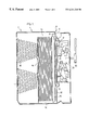
- FIG. 1 is a sectional view through the cassette
- FIG. 2 is a simplified view showing the guides and the support arrangement in an initial position for receipt of a banknote
- FIG. 3 shows initial movement of the support arrangement through the guides to start to remove a banknote from the guides
- FIG. 4 shows the relative movement of the support arrangement and the guides freeing the edges of a banknote from the guides
- FIG. 5 shows the guides returning to the initial position
- FIG. 6 shows movement of the support arrangement to the initial position such that the support arrangement and the guides are now positioned for receipt of a banknote
- FIG. 7 is a side view showing a cam actuator cooperating with a scissor linkage used to control the guides;
- FIG. 8 is a view of the cam drive arrangement as cooperation with a linkage is used to control the support arrangement
- FIG. 9 is a view similar to FIG. 8 with the support arrangement moved to an end position adding the banknote to a stack of banknotes;
- FIG. 10 is a simplified perspective view.
- the cassette 2 shown in FIG. 1 has a housing 4 with a slot opening 6 for allowing banknotes to enter the cassette. Associated with this slot opening 6 is an idler wheel 8 and a drive wheel 10 which cooperate to engage a banknote and drive it into a banknote slot 12 defined between opposed “U-shaped” guides 26 and 27 . Drive wheel 10 and idler wheel 8 are located at the slot opening 6 and drive a received banknote into the guides 26 and 27 without belts.
- the cassette to one side of the guides 26 and 27 has a banknote storage area 14 with a stack of banknotes generally shown as 13 .
- a plate 16 is attached to the springs 17 and 18 and generally bias the stack of banknotes 13 against one side of the guide members 26 and 27 .
- a moveable support 30 is located between the opposed guides 26 and 27 , and cooperates with the guides to strip a received banknote from the guide members and add it to the stack 13 banknotes.
- Movement of the guides 26 and 27 and the support arrangement 30 to cause a banknote to be stripped from the guides is controlled by the rotary cam 20 having an axis of rotation.
- the rotary cam 20 is secured in the cassette and the cam has continuous two tracks, one for engaging cam follower 22 for causing movement of the guides in a direction generally along the axis of rotation and the second t rack for cam follower 24 attached to the support 30 for moving support 30 in a direction generally along the axis of rotation.
- This cam allows opposite relative movement of the guides and the support for a superior stripping action.
- FIGS. 2, 3 , 4 , 5 and 6 show the movement imparted to the guides in the support arrangement for stripping of the banknote.
- the guides 26 and 27 are aligned with the opening slot and have received the banknote 40 .
- the guides 26 and 27 are oversized for receiving banknotes of differing widths. In this case, the depth of the “U-shaped” guides is sufficient for receiving the largest banknote centered in the slot as well as the smallest width banknote centered in the slot.
- the movable support 30 in FIG. 2 is located to one side of the banknote slot 12 and is positioned intermediary the guides 26 and 27 .
- the guides are in contact with the movable stop 31 controlled by link arm 35 .
- the stop 31 moves to a clear position when link arm 35 pivots, allowing the guides to move past the stop 31 .
- the rotary cam has now caused the support arrangement 30 to move towards the stack of banknotes 13 .
- the support now forms a stop for the stack of banknotes and the received banknotes are now in contact with the stack.
- FIG. 4 shows how the guides 26 and 27 are moved by the cam 20 in a direction away from the stack of banknotes 13 and the received banknote is stripped from the guides.
- both the support 30 and the guides 26 and 27 move relative to one another and reduce the amount of space required to strip a banknote 40 from the guides 26 and 27 .
- there is very little displacement of the stack of banknotes to add a banknote to the stack such that the energy requirements for the stacking operation is reduced and essentially constant, regardless of the size of the stack of banknotes.
- the stacked banknotes during the addition of a received banknote, undergo little displacement and are generally stationary.
- guides 26 and 27 and the support 30 are controlled by the cam.
- support 30 moves first and guides 26 and 27 move thereafter.
- Other arrangements are possible to achieve the relative movement therebetween.
- FIG. 5 shows how the guides have now been brought back to an initial position and the “U-shaped” stops 37 engage the banknote which has now been stripped from the guides.
- FIG. 6 shows how the support member 30 is now moved back to the opposite side of the guides in preparation for receiving of a banknote.
- the banknote slot 12 is now aligned with the slot 6 in the housing and is in a position for receiving a further banknote.
- the space generally shown as A in FIG. 4 is the maximum amount of space required in the cassette for the relative movements of the guides and support member. This space is less than the space required if the support member was designed to only move relative to fixed guides 26 and 27 which would also require a large shift in the stack of banknotes.
- FIG. 7 shows details of the rotary cam 20 .
- the rotary cam is engageable with a motor drive 50 shown in FIG. 1 and causes the cam followers 22 and 24 to impart the desired action to the guides 26 and 27 and the support 30 .
- the motor 50 is part of the device which receives a banknote cassette.
- FIG. 7 shows the scissor-type arrangement used to move the guides 26 and 27 in the manner described in FIGS. 2 through 6.
- the cam follower 22 moves within the cam channel 23 and imparts the desired action to the scissor-type linkage arrangement generally shown as 25 .
- the motor shaft 51 drives the rotary cam.
- FIGS. 8 and 9 illustrate the movement of the support member 30 from the banknote receipt position of FIG. 8 to the extended position for stripping of a banknote from the guides shown in FIG. 9 .
- the support member 30 is spring biased to provide a force maintaining the cam follower 24 in contact with the cam surface 29 at the end of cam member 20 .
- the cam 20 has cam followers 22 and 24 located 180° apart relative to the cam and as such cam surface 25 and cam track 23 have a similar profile.
- the 180° phase difference causes the opposite desired movement.
- the size of the cam can be kept smaller.
- the cam also allows considerate flexibility in importing the desired drive action for the linkages and the timing of these actions including accordation of the linkages.
- the single cam is driven in a single direction by motor 50 and is cost effective, as well as highly reliable.
- FIG. 10 is a perspective view illustrating the action of the rotary cam controlling support 30 and the guides 26 and 27 .
- Support 30 is shown as a transparent component to illustrate the components therebelow.
Landscapes
- Engineering & Computer Science (AREA)
- Mechanical Engineering (AREA)
- Pile Receivers (AREA)
- Sheets, Magazines, And Separation Thereof (AREA)
Abstract
Description
Claims (15)
Priority Applications (4)
| Application Number | Priority Date | Filing Date | Title |
|---|---|---|---|
| US09/118,881 US6241240B1 (en) | 1998-04-24 | 1998-07-20 | Cassette for stacking banknote |
| PCT/CA1999/000306 WO1999055610A1 (en) | 1998-04-24 | 1999-04-16 | Cassette for stacking banknote |
| CN99805401A CN1099991C (en) | 1998-04-24 | 1999-04-16 | Cassette for stacking banknote |
| EP99913048A EP1073602B1 (en) | 1998-04-24 | 1999-04-16 | Cassette for stacking banknote |
Applications Claiming Priority (2)
| Application Number | Priority Date | Filing Date | Title |
|---|---|---|---|
| CA002235781A CA2235781C (en) | 1998-04-24 | 1998-04-24 | Cassette for stacking banknote |
| US09/118,881 US6241240B1 (en) | 1998-04-24 | 1998-07-20 | Cassette for stacking banknote |
Publications (1)
| Publication Number | Publication Date |
|---|---|
| US6241240B1 true US6241240B1 (en) | 2001-06-05 |
Family
ID=25680164
Family Applications (1)
| Application Number | Title | Priority Date | Filing Date |
|---|---|---|---|
| US09/118,881 Expired - Lifetime US6241240B1 (en) | 1998-04-24 | 1998-07-20 | Cassette for stacking banknote |
Country Status (4)
| Country | Link |
|---|---|
| US (1) | US6241240B1 (en) |
| EP (1) | EP1073602B1 (en) |
| CN (1) | CN1099991C (en) |
| WO (1) | WO1999055610A1 (en) |
Cited By (14)
| Publication number | Priority date | Publication date | Assignee | Title |
|---|---|---|---|---|
| US6375185B1 (en) * | 2000-10-20 | 2002-04-23 | Gamemax Corporation | Paper currency receiving control assembly for currency-coin exchange machine |
| US6557757B1 (en) * | 1999-10-29 | 2003-05-06 | Ncr Corporation | Media cassette for self-service terminal |
| US20030137095A1 (en) * | 2001-01-31 | 2003-07-24 | Yukio Ito | Sheet processor and method of opening and closing sheet feed route of the sheet processor |
| US20030214095A1 (en) * | 2002-05-20 | 2003-11-20 | Allen Michael S. | Compact stacker for notes of various widths |
| US20040033832A1 (en) * | 2002-08-13 | 2004-02-19 | Gregg Solomon | Casino money handling system |
| US20050078864A1 (en) * | 2000-07-17 | 2005-04-14 | Japan Cash Machine Co., Ltd. | Bill handling apparatus |
| US20050234589A1 (en) * | 2002-05-15 | 2005-10-20 | Tadashi Hatamachi | Bill processing device |
| US20060225987A1 (en) * | 2005-04-06 | 2006-10-12 | International Currency Technologies Corporation | Bill cabinet |
| WO2007019694A1 (en) * | 2005-08-19 | 2007-02-22 | Crane Canada Co. | Banknote cassette |
| WO2007019698A2 (en) | 2005-08-19 | 2007-02-22 | Crane Canada Co. | Drive mechanism for stacker linkage |
| US20110006471A1 (en) * | 2008-03-11 | 2011-01-13 | Universal Entertainment Corporation | Paper sheet handling device |
| US9251636B2 (en) | 2014-01-29 | 2016-02-02 | Japan Cash Machine Co., Ltd. | Document validating/stacking device |
| US20160221786A1 (en) * | 2013-09-13 | 2016-08-04 | Japan Cash Machine, Co., Ltd. | Stacker for storing documents |
| CN106144791A (en) * | 2016-08-31 | 2016-11-23 | 上海古鳌电子科技股份有限公司 | A kind of bill storage device |
Families Citing this family (4)
| Publication number | Priority date | Publication date | Assignee | Title |
|---|---|---|---|---|
| DE102010004582A1 (en) * | 2010-01-14 | 2011-07-21 | WINCOR NIXDORF International GmbH, 33106 | Device for handling notes of value |
| RU2692221C1 (en) * | 2015-06-08 | 2019-06-21 | Кастом С.П.А. | Paper anti-jamming device for printing apparatus with a stacker |
| CN107689102B (en) * | 2017-09-30 | 2023-11-14 | 深圳怡化电脑股份有限公司 | Lower core and financial equipment |
| CN107833358A (en) * | 2017-12-18 | 2018-03-23 | 上海古鳌电子科技股份有限公司 | A kind of banknote ejecting device |
Citations (4)
| Publication number | Priority date | Publication date | Assignee | Title |
|---|---|---|---|---|
| JPS5781050A (en) * | 1980-11-07 | 1982-05-20 | Fuji Electric Co Ltd | Device for receiving sheets of paper |
| JPS5964469A (en) | 1982-09-30 | 1984-04-12 | Fujitsu Ltd | Paper sheets containing mechanism |
| JPS62290671A (en) | 1986-06-10 | 1987-12-17 | Fuji Electric Co Ltd | Stacking/storing mechanism for paper sheets |
| US5564691A (en) | 1993-11-05 | 1996-10-15 | Kabushiki Kaisha Nippon Conlux | Bill processor |
-
1998
- 1998-07-20 US US09/118,881 patent/US6241240B1/en not_active Expired - Lifetime
-
1999
- 1999-04-16 WO PCT/CA1999/000306 patent/WO1999055610A1/en active IP Right Grant
- 1999-04-16 EP EP99913048A patent/EP1073602B1/en not_active Expired - Lifetime
- 1999-04-16 CN CN99805401A patent/CN1099991C/en not_active Expired - Fee Related
Patent Citations (4)
| Publication number | Priority date | Publication date | Assignee | Title |
|---|---|---|---|---|
| JPS5781050A (en) * | 1980-11-07 | 1982-05-20 | Fuji Electric Co Ltd | Device for receiving sheets of paper |
| JPS5964469A (en) | 1982-09-30 | 1984-04-12 | Fujitsu Ltd | Paper sheets containing mechanism |
| JPS62290671A (en) | 1986-06-10 | 1987-12-17 | Fuji Electric Co Ltd | Stacking/storing mechanism for paper sheets |
| US5564691A (en) | 1993-11-05 | 1996-10-15 | Kabushiki Kaisha Nippon Conlux | Bill processor |
Non-Patent Citations (3)
| Title |
|---|
| Patent Abstracts of Japan vol 012, No. 179 (M-701) May 26, 1988 -& JP 62 290671 A (Fuji Electric Co. Ltd.) Dec. 17, 1987 abstract; figures. |
| Patent Abstracts of Japan vol. 006 No. 167 (M-153) Aug. 31, 1982-JP 57 081050 A (Fuji Electric Co. Ltd.), May 20, 1982 abstract. |
| Patent Abstracts of Japan vol. 008, No. 170 (M-315), Aug. 7, 1984-& JP 59 064469 (Fujitsu KK), Apr. 12, 1984 abstract. |
Cited By (22)
| Publication number | Priority date | Publication date | Assignee | Title |
|---|---|---|---|---|
| US6557757B1 (en) * | 1999-10-29 | 2003-05-06 | Ncr Corporation | Media cassette for self-service terminal |
| US7192023B2 (en) * | 2000-07-17 | 2007-03-20 | Japan Cash Machine Co., Ltd. | Bill handling apparatus |
| US20050078864A1 (en) * | 2000-07-17 | 2005-04-14 | Japan Cash Machine Co., Ltd. | Bill handling apparatus |
| US6375185B1 (en) * | 2000-10-20 | 2002-04-23 | Gamemax Corporation | Paper currency receiving control assembly for currency-coin exchange machine |
| US20030137095A1 (en) * | 2001-01-31 | 2003-07-24 | Yukio Ito | Sheet processor and method of opening and closing sheet feed route of the sheet processor |
| US6948607B2 (en) * | 2001-01-31 | 2005-09-27 | Nippon Conlux Co., Ltd. | Sheet handling apparatus and method for opening/closing sheet transport path in the handling apparatus |
| US20050234589A1 (en) * | 2002-05-15 | 2005-10-20 | Tadashi Hatamachi | Bill processing device |
| US20030214095A1 (en) * | 2002-05-20 | 2003-11-20 | Allen Michael S. | Compact stacker for notes of various widths |
| US6698751B2 (en) * | 2002-05-20 | 2004-03-02 | Money Controls, Inc. | Compact stacker for notes of various widths |
| US20040033832A1 (en) * | 2002-08-13 | 2004-02-19 | Gregg Solomon | Casino money handling system |
| US20060225987A1 (en) * | 2005-04-06 | 2006-10-12 | International Currency Technologies Corporation | Bill cabinet |
| WO2007019694A1 (en) * | 2005-08-19 | 2007-02-22 | Crane Canada Co. | Banknote cassette |
| WO2007019698A2 (en) | 2005-08-19 | 2007-02-22 | Crane Canada Co. | Drive mechanism for stacker linkage |
| CN101300605B (en) * | 2005-08-19 | 2010-05-19 | 天鹤加拿大公司 | Banknote cassette |
| AU2006281883B2 (en) * | 2005-08-19 | 2012-01-19 | Crane Canada Co. | Banknote cassette |
| US20110006471A1 (en) * | 2008-03-11 | 2011-01-13 | Universal Entertainment Corporation | Paper sheet handling device |
| US8167301B2 (en) * | 2008-03-11 | 2012-05-01 | Universal Entertainment Corporation | Paper sheet handling device |
| US20160221786A1 (en) * | 2013-09-13 | 2016-08-04 | Japan Cash Machine, Co., Ltd. | Stacker for storing documents |
| US9643810B2 (en) * | 2013-09-13 | 2017-05-09 | Japan Cash Machine Co., Ltd. | Stacker for storing documents |
| US9251636B2 (en) | 2014-01-29 | 2016-02-02 | Japan Cash Machine Co., Ltd. | Document validating/stacking device |
| US9598256B2 (en) | 2014-01-29 | 2017-03-21 | Japan Cash Machine, Co., Ltd. | Document validating/stacking device |
| CN106144791A (en) * | 2016-08-31 | 2016-11-23 | 上海古鳌电子科技股份有限公司 | A kind of bill storage device |
Also Published As
| Publication number | Publication date |
|---|---|
| WO1999055610A1 (en) | 1999-11-04 |
| CN1298365A (en) | 2001-06-06 |
| CN1099991C (en) | 2003-01-29 |
| EP1073602A1 (en) | 2001-02-07 |
| EP1073602B1 (en) | 2005-06-08 |
Similar Documents
| Publication | Publication Date | Title |
|---|---|---|
| US6241240B1 (en) | Cassette for stacking banknote | |
| US6064544A (en) | Information medium conveying method and apparatus | |
| EP0339687B1 (en) | Cartridge tape drive | |
| US6126036A (en) | Apparatus for dispensing articles | |
| US6250552B1 (en) | Card reader having means for reducing the size of the card reader | |
| EP1934954B1 (en) | Drive mechanism for stacker linkage | |
| US5099292A (en) | Finisher for an image forming apparatus | |
| CA2235781C (en) | Cassette for stacking banknote | |
| US7987474B2 (en) | Disc ejecting device for slot-in type disc drive | |
| JP2010252115A (en) | Slide mechanism and opening/closing type electronic apparatus with the same | |
| KR970005355B1 (en) | Device for storing magnetic tape cassettes | |
| JPWO2007029868A1 (en) | Rotary encoder and drive device | |
| JP2002032820A (en) | Bill processing apparatus | |
| CN221719146U (en) | Card storage protection box | |
| US20230202726A1 (en) | Inner buckling type tool box | |
| JP2609155B2 (en) | Stacking device for paper sheets | |
| JP3602883B2 (en) | Card-shaped media ejection mechanism | |
| KR970003668B1 (en) | Jogger apparatus for a tray | |
| KR100773464B1 (en) | Small disk blocking apparatus for disk drive | |
| JPH03250389A (en) | Mobile punch type magnetic card reader | |
| JP3472049B2 (en) | Head moving mechanism | |
| JP2002362767A (en) | Book carry-out device | |
| JP3517878B2 (en) | Cassette mounting device | |
| KR0136584Y1 (en) | Head moving apparatus of deck mechanism for head phone stereo | |
| JPH0311015B2 (en) |
Legal Events
| Date | Code | Title | Description |
|---|---|---|---|
| AS | Assignment |
Owner name: CASHCODE COMPANY INC., CANADA Free format text: ASSIGNMENT OF ASSIGNORS INTEREST;ASSIGNOR:BUKHMAN, SERGEY;REEL/FRAME:009340/0663 Effective date: 19980515 |
|
| STCF | Information on status: patent grant |
Free format text: PATENTED CASE |
|
| FPAY | Fee payment |
Year of fee payment: 4 |
|
| FEPP | Fee payment procedure |
Free format text: PAT HOLDER NO LONGER CLAIMS SMALL ENTITY STATUS, ENTITY STATUS SET TO UNDISCOUNTED (ORIGINAL EVENT CODE: STOL); ENTITY STATUS OF PATENT OWNER: LARGE ENTITY |
|
| AS | Assignment |
Owner name: CRANE CANADA CO., CANADA Free format text: ASSIGNMENT OF ASSIGNORS INTEREST;ASSIGNOR:CASHCODE COMPANY INC.;REEL/FRAME:021590/0398 Effective date: 20060117 Owner name: CRANE CANADA CO.,CANADA Free format text: ASSIGNMENT OF ASSIGNORS INTEREST;ASSIGNOR:CASHCODE COMPANY INC.;REEL/FRAME:021590/0398 Effective date: 20060117 |
|
| FPAY | Fee payment |
Year of fee payment: 8 |
|
| FPAY | Fee payment |
Year of fee payment: 12 |