US6238556B1 - Filtration system including a back washable pre-filtration apparatus - Google Patents
Filtration system including a back washable pre-filtration apparatus Download PDFInfo
- Publication number
- US6238556B1 US6238556B1 US09/411,733 US41173399A US6238556B1 US 6238556 B1 US6238556 B1 US 6238556B1 US 41173399 A US41173399 A US 41173399A US 6238556 B1 US6238556 B1 US 6238556B1
- Authority
- US
- United States
- Prior art keywords
- vessel
- filtration apparatus
- liquid
- bed
- fluid outlet
- Prior art date
- Legal status (The legal status is an assumption and is not a legal conclusion. Google has not performed a legal analysis and makes no representation as to the accuracy of the status listed.)
- Expired - Fee Related
Links
- 238000011045 prefiltration Methods 0.000 title claims abstract description 183
- 238000001914 filtration Methods 0.000 title claims abstract description 131
- 239000007788 liquid Substances 0.000 claims abstract description 133
- 239000012530 fluid Substances 0.000 claims abstract description 124
- 238000011001 backwashing Methods 0.000 claims abstract description 48
- 239000013618 particulate matter Substances 0.000 claims abstract description 30
- 238000004891 communication Methods 0.000 claims description 19
- 239000000356 contaminant Substances 0.000 claims description 4
- 238000007599 discharging Methods 0.000 claims 3
- 239000002699 waste material Substances 0.000 description 28
- 230000037452 priming Effects 0.000 description 15
- 239000011324 bead Substances 0.000 description 14
- 239000000463 material Substances 0.000 description 8
- XLYOFNOQVPJJNP-UHFFFAOYSA-N water Substances O XLYOFNOQVPJJNP-UHFFFAOYSA-N 0.000 description 6
- 239000002245 particle Substances 0.000 description 4
- 230000003247 decreasing effect Effects 0.000 description 3
- 239000011521 glass Substances 0.000 description 3
- 230000005484 gravity Effects 0.000 description 3
- 241000251468 Actinopterygii Species 0.000 description 2
- 241000894006 Bacteria Species 0.000 description 2
- 235000008331 Pinus X rigitaeda Nutrition 0.000 description 2
- 241000018646 Pinus brutia Species 0.000 description 2
- 235000011613 Pinus brutia Nutrition 0.000 description 2
- 238000010276 construction Methods 0.000 description 2
- 239000012535 impurity Substances 0.000 description 2
- 230000000977 initiatory effect Effects 0.000 description 2
- 230000013011 mating Effects 0.000 description 2
- 238000000034 method Methods 0.000 description 2
- 238000005086 pumping Methods 0.000 description 2
- 239000007787 solid Substances 0.000 description 2
- 229910001220 stainless steel Inorganic materials 0.000 description 2
- 239000010935 stainless steel Substances 0.000 description 2
- OYPRJOBELJOOCE-UHFFFAOYSA-N Calcium Chemical compound [Ca] OYPRJOBELJOOCE-UHFFFAOYSA-N 0.000 description 1
- 244000025254 Cannabis sativa Species 0.000 description 1
- 241000238631 Hexapoda Species 0.000 description 1
- 244000057845 Pinus roxburghii Species 0.000 description 1
- 229910052791 calcium Inorganic materials 0.000 description 1
- 239000011575 calcium Substances 0.000 description 1
- 239000003610 charcoal Substances 0.000 description 1
- 230000002708 enhancing effect Effects 0.000 description 1
- 210000003608 fece Anatomy 0.000 description 1
- 238000011010 flushing procedure Methods 0.000 description 1
- 239000008187 granular material Substances 0.000 description 1
- 239000011236 particulate material Substances 0.000 description 1
- 239000011148 porous material Substances 0.000 description 1
- 238000012827 research and development Methods 0.000 description 1
- 239000011435 rock Substances 0.000 description 1
- 239000004576 sand Substances 0.000 description 1
- 239000002689 soil Substances 0.000 description 1
- 230000001960 triggered effect Effects 0.000 description 1
- 238000004065 wastewater treatment Methods 0.000 description 1
Images


Classifications
-
- B—PERFORMING OPERATIONS; TRANSPORTING
- B01—PHYSICAL OR CHEMICAL PROCESSES OR APPARATUS IN GENERAL
- B01D—SEPARATION
- B01D37/00—Processes of filtration
- B01D37/04—Controlling the filtration
-
- B—PERFORMING OPERATIONS; TRANSPORTING
- B01—PHYSICAL OR CHEMICAL PROCESSES OR APPARATUS IN GENERAL
- B01D—SEPARATION
- B01D24/00—Filters comprising loose filtering material, i.e. filtering material without any binder between the individual particles or fibres thereof
- B01D24/02—Filters comprising loose filtering material, i.e. filtering material without any binder between the individual particles or fibres thereof with the filter bed stationary during the filtration
- B01D24/10—Filters comprising loose filtering material, i.e. filtering material without any binder between the individual particles or fibres thereof with the filter bed stationary during the filtration the filtering material being held in a closed container
- B01D24/16—Upward filtration
- B01D24/167—Upward filtration the container having distribution or collection headers or pervious conduits
-
- B—PERFORMING OPERATIONS; TRANSPORTING
- B01—PHYSICAL OR CHEMICAL PROCESSES OR APPARATUS IN GENERAL
- B01D—SEPARATION
- B01D24/00—Filters comprising loose filtering material, i.e. filtering material without any binder between the individual particles or fibres thereof
- B01D24/36—Filters comprising loose filtering material, i.e. filtering material without any binder between the individual particles or fibres thereof with the filter bed fluidised during the filtration
-
- B—PERFORMING OPERATIONS; TRANSPORTING
- B01—PHYSICAL OR CHEMICAL PROCESSES OR APPARATUS IN GENERAL
- B01D—SEPARATION
- B01D24/00—Filters comprising loose filtering material, i.e. filtering material without any binder between the individual particles or fibres thereof
- B01D24/38—Feed or discharge devices
- B01D24/40—Feed or discharge devices for feeding
- B01D24/407—Feed or discharge devices for feeding provoking a tangential stream
-
- B—PERFORMING OPERATIONS; TRANSPORTING
- B01—PHYSICAL OR CHEMICAL PROCESSES OR APPARATUS IN GENERAL
- B01D—SEPARATION
- B01D24/00—Filters comprising loose filtering material, i.e. filtering material without any binder between the individual particles or fibres thereof
- B01D24/46—Regenerating the filtering material in the filter
- B01D24/4631—Counter-current flushing, e.g. by air
- B01D24/4636—Counter-current flushing, e.g. by air with backwash shoes; with nozzles
-
- C—CHEMISTRY; METALLURGY
- C02—TREATMENT OF WATER, WASTE WATER, SEWAGE, OR SLUDGE
- C02F—TREATMENT OF WATER, WASTE WATER, SEWAGE, OR SLUDGE
- C02F2103/00—Nature of the water, waste water, sewage or sludge to be treated
- C02F2103/42—Nature of the water, waste water, sewage or sludge to be treated from bathing facilities, e.g. swimming pools
Definitions
- U.S. Pat. No. 4,322,296 discloses a method for waste water treatment in a vessel having a fixed perforated plate and a movable perforated plate.
- a particulate carrier having a specific gravity greater than water is employed as the filtering medium within the vessel.
- U.S. Pat. No. 5,453,183 discloses a fluidized bed biological filter system for fish tanks. This system utilizes glass beads having a specific gravity greater than 1.5 times that of water as particulate media.
- the present invention is a filtration system for filtering particulate matter from a liquid.
- the filtration system comprises a pre-filtration apparatus and a main filtration apparatus.
- the pre-filtration apparatus comprises a vessel having a fluid inlet, a fluid outlet, and a back-washing outlet, and a filtering medium disposed in the vessel and capable of filtering large particulate matter from the liquid and passing fine particulate matter.
- the fluid inlet and the fluid outlet are positioned such that liquid flowing therebetween is passed through the filtering medium.
- the fluid outlet and back-washing outlet are positioned such that liquid flowing therebetween is passed through the filtering medium.
- the main filtration apparatus comprises a vessel having a fluid inlet, a fluid outlet, and a filtering medium disposed in the vessel and capable of filtering fine particulate matter from the liquid.
- the fluid inlet and the fluid outlet are positioned such that liquid flowing therebetween is passed through the filtering medium.
- a pump is fluidly connected between the pre-filtration apparatus and the main filtration apparatus.
- the pump has a suction side and a discharge side.
- a pre-filter control assembly is fluidly connected between the pre-filtration apparatus and the pump.
- the pre-filter control assembly has a normal operation setting wherein the fluid outlet of the pre-filtration apparatus is fluidly connected to the suction side of the pump to draw liquid sequentially through the fluid inlet of the pre-filtration apparatus, and the filtering medium of the pre-filtration apparatus.
- the pre-filter control assembly is also provided with a back wash operation setting wherein the fluid outlet of the pre-filtration apparatus is fluidly connected to the discharge side of the pump to force liquid sequentially through the fluid outlet of the pre-filtration apparatus, the filtering medium of the pre-filtration apparatus, and the fluid outlet of the pre-filtration apparatus.
- the pre-filtration apparatus functions as a vacuum container during normal operation and as a pressurized container during back wash.
- the fluid outlet of the pre-filtration apparatus is offset laterally from a centrally disposed elongated axis of the vessel of the pre-filtration apparatus.
- the lateral offset of the fluid outlet causes a turbulent vortex to form in the pre-filtration apparatus during back washing to more effectively scour and remove the accumulated particulate matter from the filtering medium.
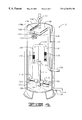
- FIG. 1 is a front elevational representation of a pre-filtration apparatus constructed in accordance with the present invention.
- FIG. 2 is a back cross-sectional representation of the pre-filtration apparatus depicted in FIG. 1 .
- FIG. 3 is a cross-sectional representation of a portion of the pre-filtration apparatus taken along the lines 3 — 3 of FIG. 2 .
- FIG. 4 is a partially diagrammatical representation of a main filtration apparatus constructed in accordance with the present invention.
- FIG. 5 is a diagrammatical representation of a filtration system constructed in accordance with the present invention wherein the pre-filtration apparatus and the main filtration apparatus are both operating in a normal mode.
- FIG. 6 is a diagrammatical representation of the filtration system depicted in FIG. 6 wherein the pre-filtration apparatus is operating in a back wash mode.
- FIG. 7 is a diagrammatical representation of the filtration system depicted in FIG. 6 wherein the pre-filtration apparatus is operating in the normal mode and the main filtration apparatus is operating in a back wash mode.
- FIG. 1 shown therein and designated by the reference numeral 10 is a pre-filtration apparatus constructed in accordance with the present invention which functions as a vacuum container during normal operation and as a pressurized container during back wash.
- the pre-filter apparatus 10 is thus capable of pre-filtering contaminated liquid before such contaminated liquid is transferred to a main filtration apparatus 12 (FIG. 4 ).
- FIGS. 4 see FIGS.
- contaminated liquid such as water from a decorative pond, pool, fish tank or the like
- pre-filtration apparatus 10 which pre-filters out large particular matter such as pine needles, bird droppings, and leaves from the contaminated liquid
- main filtration apparatus 12 which filters out the smaller particulate matter, such as dirt.
- the pre-filtration apparatus 10 functions as a pressurized container.
- the pre-filtration apparatus 10 includes a vessel 14 and a filtering medium, such as a bed of positively buoyant particulate 16 (FIG. 2 ). Only isolated portions of the bed of positively buoyant particulate 16 is shown in FIG. 2 for purposes of clarity.
- the bed of positively buoyant particulate 16 is disposed in the vessel 14 and suspended in a liquid 18 .
- the contaminated liquid is passed through the bed of positively buoyant particulate 16 so as to strain or filter out the large particulate matter, i.e. pine needles, leaves, grass and the like, in the contaminated liquid.
- the quantity of positively buoyant particulate 16 is adequate to provide the filtering medium extending in the upper thirty to fifty percent of the vessel 14 .
- the amount of positively buoyant particulate 16 used may be increased or decreased depending on the type of liquid being filtered and the desired filtering results.
- the dimensions and quantities of positively buoyant particulate 16 affect the filtering efficiency and the throughput of the pre-filtration apparatus 10 .
- small volumes of coarse particulate result in greater throughput but with fewer impurities removed from the contaminated liquid.
- large quantities of fine particulate produce better filtration but reduced throughput or increased pumping requirements to pull the contaminated liquid through the pre-filtration apparatus 10 .
- the sizes and quantities of positively buoyant particulate 16 should be selected according to the filtration characteristics desired.
- the vessel 14 has a medial portion 20 and a lower end 22 .
- the medial portion 20 supports a cap assembly 24 of the vessel 14 in a fluid tight relationship therewith. Due to its buoyancy, the bed of positively buoyant particulate 16 is amassed in the medial portion 20 and the cap assembly 24 of the vessel 14 .
- the lower end 22 of the vessel 14 forms a stand 26 for supporting the pre-filtration apparatus 10 .
- a fluid inlet 30 is formed through the lower end 22 of the vessel 14 such that liquid can pass through the fluid inlet 30 and into the vessel 14 during a normal mode of operation of the pre-filtration apparatus 10 .
- a back washing outlet 32 is formed through the lower end 22 of the vessel 14 such that liquid and the large particulate matter previously accumulated in the bed of positively buoyant particulate 16 can pass out of the vessel 14 through the back washing outlet 32 during a back washing mode of operation of the pre-filtration apparatus 10 .
- a drain outlet 34 is also formed through the lower end 22 of the vessel 14 so that liquid can be drained out of the vessel 14 , if desired.
- An inner tube 36 is supported in the lower end 22 of the vessel 14 so as to channel liquid passing through the fluid inlet 30 upwardly towards the bed of positively buoyant particulate 16 during the normal mode of operation of the pre-filtration apparatus 10 .
- an annular lip 38 extends outwardly from an upper end 40 of the inner tube 36 so as to form an annular fluid discharge passageway 42 in fluid communication with the vessel 14 , and also in fluid communication with the back washing outlet 32 .
- the annular lip 38 is sized so that the positively buoyant particulate 16 cannot pass through the annular fluid discharge passage way 42 during the back washing mode of operation.
- a plurality of external threads 44 are formed on an exterior surface 46 of the vessel 14 , generally near the medial portion 20 thereof.
- the external threads 44 threadingly receive an external collar 48 for maintaining the cap assembly 24 in the fluid tight relationship with the medial portion 20 of the vessel 14 .
- the cap assembly 24 of the vessel 14 includes an upper portion 52 and a lower portion 54 .
- An outwardly extending shoulder 56 is formed on the lower portion 54 for mating engagement with the medial portion 20 of the vessel 14 .
- a portion of the external collar 48 extends over the shoulder 56 for securely maintaining the cap assembly 24 on the medial portion 20 of the vessel 14 .
- the upper portion 52 and the lower portion 54 of the cap assembly 24 are in fluid communication.
- the upper portion 52 has a diameter which is less than the diameter of the lower portion 54 .
- the vessel 14 has a fluid outlet 58 formed through the upper portion 52 of the cap assembly 24 so that the fluid outlet 58 is in fluid communication with the upper portion 52 of the cap assembly 24 .
- the fluid outlet 58 is laterally offset from a centrally disposed, elongated axis 60 of the vessel 14 so as to create a turbulent vortex in the cap assembly 24 and the vessel 14 so as to more effectively scour and clean the positively buoyant particulate 16 during the back washing mode of operation of the pre-filtration apparatus 10 .
- the vessel 14 includes a strainer assembly 64 supported in a cavity 66 defined by the lower portion 54 of the cap assembly 24 so as to prevent the positively buoyant particulate 16 from exiting through the fluid outlet 58 during the normal mode of operation of the pre-filtration apparatus 10 .
- the strainer assembly 64 is connected to a downwardly extending annular flange 68 , which is connected to the lower portion 54 of the cap assembly 24 .
- the strainer assembly 64 includes a strainer body 70 having a plurality of slots 72 formed there through. The slots 72 are in fluid communication with the fluid outlet 58 for a purpose to be described hereinafter.
- contaminated liquid such as contaminated water from a decorative pond, pool or aquarium
- the fluid inlet 30 contaminated water from a decorative pond, pool or aquarium
- the bed of positively buoyant particulate 16 is passed sequentially through the fluid inlet 30 , the bed of positively buoyant particulate 16 , the slots 72 and the fluid outlet 58 .
- the large particulate matter in the contaminated liquid accumulates in the bed of positively buoyant particulate 16 so as to filter or strain out the large particulate matter in the contaminated liquid.
- liquid is passed sequentially through the fluid outlet 58 , the slots 72 , the bed of positively buoyant particulate 16 , and the back washing outlet 32 .
- the lateral offset position of the fluid outlet 58 causes a vortex to form in the vessel 14 so as to turbulently agitate and separate the individual positively buoyant particulate in the bed of positively buoyant particulate 16 during the back washing mode of operation to more effectively remove the accumulated large particulate matter therefrom.
- the vessel includes a priming assembly 74 connected to the upper portion 52 of the cap assembly 24 .
- the priming assembly 74 includes a priming tube 76 in fluid communication with the upper portion 52 , and a priming cap 78 removably secured to the priming tube 76 .
- the priming cap 78 is removed from the priming tube 76 and the liquid 18 is added through the priming tube 76 until the vessel 14 , the cap assembly 24 and the priming tube 76 are filled with liquid.
- the priming cap 78 is replaced on the priming tube 76 so as to form a fluid tight seal there with, and the pre-filtration apparatus 10 can then be operated in either of the normal mode or back washing mode of operations.
- the priming cap 78 can be removably secured to the priming tube 76 by any suitable assembly, such as mating threads (not shown) disposed on the priming cap 78 and the priming tube 76 .
- the bed of positively buoyant particulate 16 contained in the vessel 14 may comprise a wide variety of materials.
- Positively buoyant polymeric beads are a preferred positively buoyant particulate.
- the beads may be solid, porous, hollow, air-filled, vacuum-filled, gas-filled, or any other bead which is positively buoyant in the liquid to be filtered.
- the size and shape of the positively buoyant particulate may be varied greatly as long as the bed of positively buoyant particulate 16 define a medium which is porous to liquids disposed in the vessel 14 .
- the positively buoyant particulate should have dimensions such that it will neither pass through nor clog the slots 72 in the strainer assembly 64 or the fluid discharge passageway 42 .
- the main filtration apparatus 12 is constructed and operated in an identical manner as the filtering apparatus 10 b described in U.S. Pat. No. 5,932,092, except as discussed hereinafter.
- the entire content of U.S. Pat. No. 5,932,092, relating to the filtering apparatus 10 b is hereby incorporated herein by reference.
- the main filtration apparatus 12 includes a vessel 100 for housing a filtering medium, such as a bed of positively buoyant particulate 102 and a bed of negatively buoyant particulate 104 in a manner identical to that described in U.S. Pat. No. 5,932,092, the content of which is incorporated herein by reference.
- a filtering medium such as a bed of positively buoyant particulate 102 and a bed of negatively buoyant particulate 104 in a manner identical to that described in U.S. Pat. No. 5,932,092, the content of which is incorporated herein by reference.
- the beds of positively and negatively buoyant particulates 102 and 104 function as filtering mediums to filter out the smaller particulate matter which was not previously filtered out by the pre-filtration apparatus 10 .
- the vessel 100 is characterized as having an upper end 106 and a lower end 108 .
- the main filtration apparatus 12 further includes a lower conduit assembly 110 forming a fluid inlet of the vessel 100 , and an upper conduit
- the vessel 100 is similar to the vessels 12 and 12 a described in U.S. Pat. No. 5,932,092 (the content of which is incorporated herein by reference), except as noted below. Thus, for the sake of brevity, a detailed discussion of such components will not be repeated herein with reference to the main filtration apparatus 12 .
- the lower conduit assembly 110 includes a primary conduit 114 , a pair of lateral conduits 116 a and 116 b , and a discharge conduit 118 .
- the primary conduit 114 has one end disposed within the vessel 100 proximate the lower end 108 thereof.
- the lateral conduits 116 a and 116 b each have an inlet end connected to the primary conduit 114 and extend outwardly therefrom.
- Each lateral conduit 116 a and 116 b has a slotted area 122 a and 122 b , respectively, positioned within the bed of negatively buoyant particulate 104 .
- a check valve 124 is interposed between the primary conduit 114 and the lateral conduit 116 a
- a check valve 126 is interposed between the primary conduit 114 and the lateral conduit 116 b .
- the check valves 124 and 126 are directionally positioned to allow liquid to pass through the check valves 124 and 126 as liquid flows in a direction from the primary conduit 114 to the lateral conduits 116 a and 116 b.
- the discharge conduit 118 has a main tube 128 , which is connected to the primary conduit 114 so as to establish fluid communication therebetween, and a pair of branch tubes 130 a and 130 b .
- Each branch tube 130 a and 130 b has a slotted area 132 a and 132 b , respectively.
- the discharge conduit 118 is supported within the vessel 100 so that the slotted areas 132 a and 132 b are positioned between the bed of positively buoyant particulate 102 and the bed of negatively buoyant particulate 104 when the main filtration apparatus 12 is in operation.
- a check valve 134 is interposed between the main tube 128 of the discharge conduit 118 and the primary conduit 114 .
- the check valve 134 is directionally positioned to allow liquid to pass through the check valve 134 as liquid flows in a direction from the discharge conduit 118 to the primary conduit 114 .
- the upper conduit assembly 112 includes a primary conduit 136 having one end extended into the vessel 100 proximate the upper end 106 thereof, as substantially shown in FIG. 4 .
- the primary conduit 136 is provided with a pair of slotted areas 138 a and 138 b which are positioned within the bed of positively buoyant particulate 102 .
- the slotted area 138 b has a smaller area than the slotted area 138 a .
- the slotted area 138 b may only be formed in the top of the primary conduit 136 so that the slotted area 138 b faces upwardly, while the slotted area 138 a may be formed in the top and sides of the primary conduit 136 .
- a check valve 140 is interposed in between the slotted areas 138 a and 138 b .
- the check valve is directionally positioned to allow liquid to pass through the check valve as liquid flows in a direction from the slotted area 138 a to the slotted area 138 b .
- the check valve 140 can be a commercially available swing check valve.
- a vent conduit 142 extends upwardly through the upper end 106 of the vessel 100 .
- the vent conduit 142 is provided with a manual relief valve 144 , for permitting the selective release of gaseous fluids trapped in the upper end 106 of the vessel 100 .
- the bed of positively buoyant particulate 102 contained in the vessel 100 may comprise a wide variety of materials.
- Positively buoyant polymeric beads are a preferred positively buoyant particulate.
- the beads may be solid, porous, hollow, air-filled, vacuum-filled, gas-filled, or any other bead which is positively buoyant in the liquid to be filtered.
- the size and shape of the positively buoyant particulate may be varied greatly as long as the positively buoyant particulate define a medium which is porous to a liquids disposed in the vessel 100 .
- the positively buoyant particulate should have dimensions such that it will neither pass through nor clog the slots 138 a and 138 b in the primary conduit 136 .
- the quantity of positively buoyant particulate utilized is adequate to provide a bed of positively buoyant particulate for the upper ten to thirty percent of the vessel 100 .
- the amount of positively buoyant particulate used may be increased or decreased depending on the type of liquid being filtered and the desired filtering results.
- the bed of negatively buoyant particulate 104 contained in the vessel 100 may comprise a wide variety of negatively buoyant materials.
- Sand and gravel are preferred materials for the negatively buoyant particulate.
- Other materials which may be used for the negatively buoyant particulate include crushed rock, granules of charcoal or the like, stainless steel balls, stainless steel beads, metallic balls, metallic beads, glass beads, plastic beads, filled polymeric beads, glass balls, metallic balls coated with a polymeric material, metallic beads coated with a polymeric material, and polymeric beads filled with a suitable material such as calcium.
- the size and shape of the negatively buoyant particulate may be varied greatly as long as the negatively buoyant particulate define a medium which is porous to the liquid being filtered. However, the negatively buoyant particulate should have dimensions such that it will neither pass through nor clog the slotted area 122 in the lateral conduits 116 .
- the quantity of negatively buoyant particulate is adequate to provide a medium of porous material extending over the lower ten to thirty percent of the vessel 100 .
- the amount of negatively buoyant particulate used may be increased or decreased depending on the type of liquid being filtered and the desired filtering results.
- the dimensions and quantities of positively buoyant particulate and negatively buoyant particulate affect the filtering efficiency and the throughput of the main filtration apparatus 12 .
- small volumes of coarse particulate result in greater throughput but with fewer impurities removed from the liquid.
- large quantities of fine particulate produce better filtration but reduced throughput or increased pumping requirements to push the liquid through the main filtration apparatus 12 .
- the sizes and quantities of positively buoyant and negatively buoyant particulate should be selected according to the filtration characteristics desired.
- the filtration system 150 includes the pre-filtration apparatus 10 , and the main filtration apparatus 12 disposed downstream from the pre-filtration apparatus 10 .
- the filtration system 150 is also provided with a pre-filter control assembly 156 , a main filter control assembly 158 , an ultraviolet sterilizer 160 , a pump 162 , a pre-filtration waste valve 164 , and a conduit assembly 166 .
- the pre-filter control assembly 156 provides directional control of the liquids to selectively operate the pre-filtration apparatus 10 in the normal or back wash modes of operation.
- the pre-filter control assembly includes a valve body 168 defining a first port 170 , a second port 172 , a third port 174 , a fourth port 176 , and a fifth port 178 .
- the pre-filter control assembly 156 also includes a valve handle 180 which is selectively movable so as to control the flow of liquids through the first, second, third, fourth and fifth ports 170 - 178 .
- the pre-filter control assembly 156 can be a multi-port valve.
- the main filter control assembly 158 provides directional control of the liquids to selectively operate the main filter control assembly in the normal or back wash modes of operation.
- the main filter control assembly 158 includes a valve body 182 , a first port 184 , a second port 186 , a third port 188 , a fourth port 190 , a fifth port 192 , and a valve handle 194 .
- the valve handle 194 is selectively movable so as to control the flow of liquids through the first, second, third, fourth and fifth ports 184 - 192 .
- the main filter control assembly 158 can be a commercially available multi-port valve.
- the ultraviolet sterilizer 160 includes an inlet port 200 and an outlet port 202 .
- the ultraviolet sterilizer 160 can be a commercially available ultraviolet sterilizer, which is known in the art.
- the pump 162 moves the liquids 152 through the filtration system 150 .
- the pump 162 includes a suction side 204 and a discharge side 206 .
- the pump 162 can be a commercially available pump, which is known in the art.
- the size of the pump 162 can vary widely and depends on the sizes of the vessel 154 , the pre-filtration apparatus 10 , and the main filtration apparatus 12 .
- the pre-filtration waste valve 164 controls the flow of liquids 152 from the back-washing outlet 32 to a waste line 207 .
- the pre-filtration waste valve 164 includes an inlet port 208 and an outlet port 210 .
- the pre-filtration waste valve 164 can be a commercially available valve.
- the conduit assembly 166 connects the vessel 154 , pre-filtration apparatus 10 , main filtration apparatus 12 , pre-filter control assembly 156 , main filter control assembly 158 , ultraviolet sterilizer 160 , the pump 162 and the pre-filtration waste valve 164 to establish fluid communication therebetween.
- the pre-filter control assembly 156 , and the main filter control assembly 158 cooperate to provide directional control of the flow of the liquid 152 to operate the filtration system 150 in three modes of operation: a normal mode of operation (as shown in FIG. 5 with directional flow arrows), a pre-filtration apparatus back washing mode of operation (as shown in FIG. 6 with directional flow arrows), and a main filtration back washing mode of operation (as shown in FIG. 7 with directional flow arrow).
- a normal mode of operation as shown in FIG. 5 with directional flow arrows
- a pre-filtration apparatus back washing mode of operation as shown in FIG. 6 with directional flow arrows
- main filtration back washing mode of operation as shown in FIG.
- the liquid 152 is pumped from the vessel 154 , and sequentially directed through the pre-filtration apparatus 10 (from the fluid inlet 30 upwardly to the fluid outlet 58 ), the pump 162 , the main filtration apparatus 12 , and the ultraviolet sterilizer 160 .
- the filtered liquid 152 is then directed by the conduit assembly 166 back into the vessel 154 .
- the pre-filtration apparatus 10 filters out the large particles in the liquid 152 , such as pine needles and leaves, and the main filtration apparatus 12 filters out the small particles in the liquid 152 , such as soil and insect larvae.
- liquid 152 is pumped from the vessel 154 , and sequentially directed through the pump 162 , the pre-filtration apparatus 10 (from the fluid outlet 58 downwardly to the back-washing outlet 32 ), and to the waste line 207 .
- the pre-filtration apparatus back washing mode of operation removes the accumulated large particulate matter from the positively buoyant particles in the bed of positively buoyant particulate 16 .
- liquid 152 is pumped from the vessel 154 , and sequentially directed through the pre-filtration apparatus 10 (from the fluid inlet 30 upwardly to the fluid outlet 58 ), the pump 162 , through the main filtration apparatus 12 (from the primary conduit 136 of the upper conduit assembly 112 to the slots of the slotted areas 132 b ) and discharged to the waste line 207 .
- the main filtration back washing mode of operation removes the accumulated small particulate matter from the positively buoyant particles in the bed of positively buoyant particulate 102 while maintaining the bed of negatively buoyant particulate 104 in a relatively undisturbed state so as not to remove the bacteria growth from the surface of the particulate making up the bed of negatively buoyant particulate 104 .
- conduit assembly 166 for fluidly interconnecting the pre-filtration apparatus 10 , the main filtration apparatus 12 , the vessel 154 , the pre-filter control assembly 156 , the main filter control assembly 158 , the ultraviolet sterilizer 160 , the pump 162 , and the pre-filtration waste valve 164 will now be described.
- the conduit assembly 166 includes a fluid source conduit 212 .
- the fluid source conduit 212 has one end connected to the vessel 154 so as to establish fluid communication therewith and an opposite end connected to the fluid inlet 30 of the pre-filtration apparatus 10 .
- a directional check valve 214 is provided adjacent to the fluid inlet 30 so as to permit the liquid 152 to flow into the vessel 14 of the pre-filtration apparatus 10 .
- the conduit assembly 166 also includes a pre-filter upper conduit 216 .
- the pre-filter upper conduit 216 has one end connected to the fluid outlet 58 of the pre-filtration apparatus 10 and an opposite end connected to the fourth port 176 of the pre-filter control assembly 156 so as to establish fluid communication between the fluid outlet 58 and the fourth port 176 .
- the conduit assembly 166 also includes a pre-filter back wash conduit 218 .
- the pre-filter back wash conduit 218 has one end connected to the fluid source conduit 212 and an opposite end connected to the fifth port 178 of the pre-filter control assembly 156 so as to establish fluid communication there between.
- a directional check valve 220 is positioned in the pre-filter back wash conduit 218 so as to permit the flow of the liquid 152 in a direction generally toward the pre-filter control assembly 156 .
- the conduit assembly 166 is further provided with a first pump conduit 222 .
- the first pump conduit 222 has one end connected to the third port 174 of the pre-filter control assembly 156 and an opposite end connected to the suction side 204 of the pump 162 so as to establish fluid communication there between.
- the conduit assembly 166 is also provided with a second pump conduit 224 .
- the second pump conduit 224 has one end connected to the discharge side 206 of the pump 162 , and an opposite end connected to the first port 170 of the pre-filter control assembly 156 so as to establish fluid communication there between.
- the conduit assembly 166 is further provided with a pre-filter discharge conduit 226 .
- the pre-filter discharge conduit 226 has one end connected to the second port 172 of the pre-filter control assembly 156 and an opposite end connected to the second port 186 of the main filter control assembly 158 so as to establish fluid communication there between.
- the conduit assembly 166 also includes a main filter lower conduit 228 .
- the main filter lower conduit 228 has one end connected to the third port 188 of the main filter control assembly 158 and an opposite end connected to the primary conduit 244 so as to establish fluid communication there between.
- the primary conduit 136 of the main filtration apparatus 12 is connected to the fifth port 192 of the main filter control assembly 158 so as to establish fluid communication there between.
- the conduit assembly 166 also includes a main filter discharge conduit 230 .
- the main filter discharge conduit 230 has one end connected to the first port 184 of the main filter control assembly 158 and an opposite end connected to the inlet port 200 of the ultraviolet sterilizer 160 so as to establish fluid communication there between.
- the conduit assembly 166 is further provided with a fluid discharge conduit 232 .
- the fluid discharge conduit 232 has one and connected to the outlet port 202 of the ultraviolet sterilizer 160 and an opposite end positioned to discharge the liquid.
- the conduit assembly 166 is provided with a pre-filter lower conduit 238 .
- the pre-filter lower conduit 238 has one end connected to the back washing outlet 32 of the pre-filtration apparatus 10 and an opposite end connected to the inlet port 208 of the pre-filtration waste valve 164 . It should be understood that for proper operation of the pre-filtration apparatus 10 during back washing, the pre-filtration waste valve 164 should be positioned about level with or slightly above the fluid outlet 58 formed in the cap assembly 24 of the pre-filtration apparatus 10 .
- the waste line 207 is connected to the outlet port 210 of the pre-filtration waste valve 164 for discharge of the liquid utilized for back washing into the waste line 207 .
- the waste line 207 is also connected to the fourth port 190 of the main filter control assembly 158 for discharge of the liquid utilized in back washing the main filtration apparatus 12 .
- valve handles 180 and 194 of the pre-filter control assembly 156 and the main filter control assembly 158 are manipulated so as to set the pre-filter control assembly 156 and the main filter control assembly 158 into a normal mode of operation setting.
- the pre-filtration waste valve 164 is set so as to close the pre-filter lower conduit 238 .
- liquid 152 can be pre-filtered through the pre-filtration apparatus 10 .
- the pump 162 is then actuated to begin movement of the liquid 152 from the vessel 154 .
- the liquid 152 passes from the fluid source conduit 212 and through the fluid inlet 30 of the pre-filtration apparatus 10 .
- the liquid 152 passes upwardly through the vessel 14 , through the bed of positively buoyant particulate 16 , to pre-filter the liquid 152 and remove the large particulate matter therefrom.
- the liquid 152 then passes through the slots 72 formed in the strainer body 70 and then through the fluid outlet 58 and into the pre-filter upper conduit 216 .
- the pre-filtered liquid 152 passing through the fluid outlet 58 is then directed into the fourth port 176 of the pre-filter control assembly 156 .
- the pre-filtered liquid 152 then passes sequentially through the fourth port 176 , the third port 174 , the first pump conduit 222 , the first port 204 of the pump 162 , the pump 162 , the second port 206 of the pump 162 , the second pump conduit 224 , the first and second ports 170 and 172 of the pre-filter control assembly 156 and the pre-filter discharge conduit 226 .
- the liquid passing through the pre-filter discharge conduit 226 then passes through the second and third ports 186 and 188 of the main filter control assembly 158 .
- the liquid exiting the main filter control assembly 158 is then directed into the primary conduit 114 .
- the check valve 134 is forced into a closed position, and the liquid is thereby caused to pass into the lateral conduits 116 a and 116 b , through the slots of the slotted areas 122 a and 122 b , and into the bed of negatively buoyant particulate 104 .
- the liquid is forced up through the bed of negatively buoyant particulate 104 whereby the upwardly moving liquid creates a fluidized bed in which the liquid undergoes a nitrification process.
- the liquid Upon passing through the bed of negatively buoyant particulate 104 , the liquid travels up through the vessel 100 and through the bed of positively buoyant particulate 102 . Due to the upward movement of the liquid and the positive buoyancy of the bed of positively buoyant particulate 102 , the particulate which make up the bed of positively buoyant particulate 102 are compacted so as to create a filter bed which strains particulate contaminants from the liquid.
- the strained liquid then passes into the slots of the slotted areas 138 a and 138 b of the primary conduit 136 of the upper conduit assembly 112 , through the primary conduit 136 , and sequentially through the fifth and first ports 192 and 184 of the main filter control assembly 158 into the main filter discharge conduit 230 .
- the liquid is then forced through the ultraviolet sterilizer 160 via the inlet port 200 and exit port 202 thereof, and returned into the vessel 154 via the fluid discharge conduit 232 .
- Pre-Filtration Apparatus Back Washing Mode of Operation When the Pre-Filtration Apparatus Functions as a Pressurized Vessel
- valve handle 180 of the pre-filter control assembly 156 is manipulated so as to set the pre-filter control assembly 156 into a back washing mode of operation setting wherein the fluid outlet 58 of the pre-filtration apparatus 10 communicates with the discharge side 204 of the pump 162 .
- the pre-filtration waste valve 164 is set so as to open the pre-filter lower conduit assembly 238 to permit liquid to pass through the pre-filtration waste valve 164 .
- liquid is pumped from the vessel 154 , and sequentially directed through the pump 162 , and forced into the fluid outlet 58 formed in the cap assembly 24 of the pre-filtration apparatus 10 .
- the liquid is forced through the slots 72 in the strainer assembly 64 and directed downwardly into the vessel 14 and through the bed of positively buoyant particulate 16 to remove the accumulated large particulate matter therefrom.
- the positively buoyant particulate in the bed of positively buoyant particulate have a strong tendency to resist the flow of the liquid passing through the vessel 14 , which aids in the removal of the accumulated large particulate matter therefrom.
- the lateral offset position of the fluid outlet 58 in the cap assembly 24 causes a vortex to form in the cap assembly 24 and the vessel 14 so as to turbulently agitate and separate the individual positively buoyant particulate in the bed of positively buoyant particulate 16 to even more effectively remove the accumulated large particulate matter therefrom.
- the check valve 214 prevents the liquid from passing through the fluid inlet 30 .
- the liquid passing through the bed of positively buoyant particulate 16 (and large particulate matter removed from the bed of positively buoyant particulate 16 ) is then directed (under pressure) through the fluid discharge passageway defined in between the annular lip 38 and the vessel 14 and passed sequentially through the back-washing outlet 32 , the pre-filter lower conduit 238 , the pre-filtration waste valve 164 and into the waste line 207 .
- valve handles 180 and 194 of the pre-filter control assembly 156 and the main filter control assembly 158 are manipulated so as to set the pre-filter control assembly 156 into the normal mode of operation setting and the main filter control assembly 158 into a back washing mode of operation setting.
- the pre-filtration waste valve 164 is set so as to close off the pre-filter lower conduit assembly 238 .
- liquid 152 is pumped from the vessel 154 , and sequentially directed through the pre-filtration apparatus 10 (from the fluid inlet 30 upwardly to the fluid outlet 58 ), the pump 162 , the pre-filter control assembly 156 as discussed above with reference to FIG. 6, and into the pre-filter discharge conduit 226 .
- the liquid Under pressure, the liquid is then forced into the primary conduit 136 via the second and fifth ports 184 and 192 of the main filter control assembly 158 .
- the liquid is forced through the primary conduit 136 and through the slots of the slotted areas 138 b .
- the check valve 140 prevents the liquid from traveling through the slotted areas 136 a , thereby enhancing the pressure of the liquid passing through the slots of the slotted area 136 b , as compared to the liquid passing through the slotted area 272 b in the back washing mode of the filtering apparatus 10 b described in U.S. Pat. No. 5,932,092.
- the liquid passes down through the bed of positively buoyant particulate 102 thereby flushing the particulate contaminants from the bed of positively buoyant particulate 102 .
- the liquid Upon passing through the bed of positively buoyant particulate 102 , the liquid takes the path of least resistance and thus passes into the slots of the slotted areas 132 a and 132 b of the discharge conduit 118 . It will be appreciated that because the slotted areas 132 a and 132 b are positioned below the bed of positively buoyant particulate 102 and above the bed of negatively buoyant particulate 104 , the back washing liquid is circulated through the vessel 100 so as to flush or rinse the bed of positively buoyant particulate 102 while maintaining the bed of negatively buoyant particulate 104 in a relatively undisturbed state so as not to remove the bacteria growth from the surface of the particulate making up the bed of negatively buoyant particulate 104 .
- the liquid Upon entering the discharge conduit 118 , the liquid passes through the check valve 134 , through the primary conduit 114 , and through the main filter control assembly 158 (via the fifth port 192 and the fourth port 190 ) and into the waste line 207 .
- the initiation of the pre-filtration apparatus back washing mode of operation, and/or the initiation of the main filtration back washing mode of operation may be triggered (1) by pressure differential between pressure sensors arranged to determine whether the pre-filtration apparatus 10 and/or the main filtration apparatus 12 are becoming clogged with particulate contaminants, (2) at a preset time interval, or (3) by manual operation of the pre-filtration waste valvel 164 , and the valve handles 180 , and 194 of the pre-filter control assembly 156 and the main filter control assembly 158 .
- a return to the normal mode of operation may be initiated (1) by a drop in the differential pressure between pressure sensors arranged to determine whether the pre-filtration apparatus 10 and/or the main filtration apparatus 12 are becoming unclogged, (2) by a preset time interval, or (3) by manual operation of the pre-filtration waste valve 164 , and the valve handles 180 , and 194 of the pre-filter control assembly 156 and the main filter control assembly 158 .
- a suitable system for automatically determining the differential pressure across a filter apparatus is disclosed in U.S. Pat. No. 5,932,092, which content is hereby incorporated herein by reference.
Landscapes
- Chemical & Material Sciences (AREA)
- Chemical Kinetics & Catalysis (AREA)
- Filtration Of Liquid (AREA)
Abstract
A filtration system for filtering particulate matter from a liquid, the filtration system comprises a pre-filtration apparatus and a main filtration apparatus. The pre-filtration apparatus comprises a vessel having a fluid inlet, a fluid outlet, and a back-washing outlet, and a filtering medium disposed in the vessel and capable of filtering large particulate matter from the liquid and passing fine particulate matter. The fluid inlet and the fluid outlet are positioned such that liquid flowing therebetween is passed through the filtering medium. The fluid outlet and back-washing outlet are positioned such that liquid flowing therebetween is passed through the filtering medium. The main filtration apparatus comprises a vessel having a fluid inlet, a fluid outlet, and a filtering medium disposed in the vessel and capable of filtering fine particulate matter from the liquid. The fluid inlet and the fluid outlet are positioned such that liquid flowing therebetween is passed through the filtering medium. A pump is fluidly connected between the pre-filtration apparatus and the main filtration apparatus. The pump has a suction side and a discharge side. A pre-filter control assembly is fluidly connected between the pre-filtration apparatus and the pump. The pre-filter control assembly has a normal operation setting wherein the fluid outlet of the pre-filtration apparatus is fluidly connected to the suction side of the pump to draw liquid sequentially through the fluid inlet of the pre-filtration apparatus, and the filtering medium of the pre-filtration apparatus. The pre-filter control assembly is also provided with a back wash operation setting wherein the fluid outlet of the pre-filtration apparatus is fluidly connected to the discharge side of the pump to force liquid sequentially through the fluid outlet of the pre-filtration apparatus, the filtering medium of the pre-filtration apparatus, and the fluid outlet of the pre-filtration apparatus.
Description
Not applicable.
Not applicable.
Many types of fluidized beds are known in the art. For example, U.S. Pat. No. 4,322,296 discloses a method for waste water treatment in a vessel having a fixed perforated plate and a movable perforated plate. A particulate carrier having a specific gravity greater than water is employed as the filtering medium within the vessel.
As a further example, U.S. Pat. No. 5,453,183 discloses a fluidized bed biological filter system for fish tanks. This system utilizes glass beads having a specific gravity greater than 1.5 times that of water as particulate media.
In these filtration systems, contaminated water is passed through a negatively buoyant particulate medium. Thus, these systems only accomplish one type of filtration, i.e., filtration through a particulate carrier having a specific gravity greater than water.
The present invention is a filtration system for filtering particulate matter from a liquid. The filtration system comprises a pre-filtration apparatus and a main filtration apparatus. The pre-filtration apparatus comprises a vessel having a fluid inlet, a fluid outlet, and a back-washing outlet, and a filtering medium disposed in the vessel and capable of filtering large particulate matter from the liquid and passing fine particulate matter.
The fluid inlet and the fluid outlet are positioned such that liquid flowing therebetween is passed through the filtering medium. The fluid outlet and back-washing outlet are positioned such that liquid flowing therebetween is passed through the filtering medium.
The main filtration apparatus comprises a vessel having a fluid inlet, a fluid outlet, and a filtering medium disposed in the vessel and capable of filtering fine particulate matter from the liquid. The fluid inlet and the fluid outlet are positioned such that liquid flowing therebetween is passed through the filtering medium.
A pump is fluidly connected between the pre-filtration apparatus and the main filtration apparatus. The pump has a suction side and a discharge side.
A pre-filter control assembly is fluidly connected between the pre-filtration apparatus and the pump. The pre-filter control assembly has a normal operation setting wherein the fluid outlet of the pre-filtration apparatus is fluidly connected to the suction side of the pump to draw liquid sequentially through the fluid inlet of the pre-filtration apparatus, and the filtering medium of the pre-filtration apparatus. The pre-filter control assembly is also provided with a back wash operation setting wherein the fluid outlet of the pre-filtration apparatus is fluidly connected to the discharge side of the pump to force liquid sequentially through the fluid outlet of the pre-filtration apparatus, the filtering medium of the pre-filtration apparatus, and the fluid outlet of the pre-filtration apparatus. Thus, the pre-filtration apparatus functions as a vacuum container during normal operation and as a pressurized container during back wash.
In one aspect of the present invention, the fluid outlet of the pre-filtration apparatus is offset laterally from a centrally disposed elongated axis of the vessel of the pre-filtration apparatus. The lateral offset of the fluid outlet causes a turbulent vortex to form in the pre-filtration apparatus during back washing to more effectively scour and remove the accumulated particulate matter from the filtering medium.
Other advantages and features of the present invention will become apparent to those of ordinary skill in the art when the following detailed description is read in conjunction with the appended claims and the attached drawings.
FIG. 1 is a front elevational representation of a pre-filtration apparatus constructed in accordance with the present invention.
FIG. 2 is a back cross-sectional representation of the pre-filtration apparatus depicted in FIG. 1.
FIG. 3 is a cross-sectional representation of a portion of the pre-filtration apparatus taken along the lines 3—3 of FIG. 2.
FIG. 4 is a partially diagrammatical representation of a main filtration apparatus constructed in accordance with the present invention.
FIG. 5 is a diagrammatical representation of a filtration system constructed in accordance with the present invention wherein the pre-filtration apparatus and the main filtration apparatus are both operating in a normal mode.
FIG. 6 is a diagrammatical representation of the filtration system depicted in FIG. 6 wherein the pre-filtration apparatus is operating in a back wash mode.
FIG. 7 is a diagrammatical representation of the filtration system depicted in FIG. 6 wherein the pre-filtration apparatus is operating in the normal mode and the main filtration apparatus is operating in a back wash mode.
Referring now to the drawings, and in particular to FIG. 1, shown therein and designated by the reference numeral 10 is a pre-filtration apparatus constructed in accordance with the present invention which functions as a vacuum container during normal operation and as a pressurized container during back wash. The pre-filter apparatus 10 is thus capable of pre-filtering contaminated liquid before such contaminated liquid is transferred to a main filtration apparatus 12 (FIG. 4). In general, (see FIGS. 5-7) contaminated liquid, such as water from a decorative pond, pool, fish tank or the like, is directed sequentially through the pre-filtration apparatus 10, which pre-filters out large particular matter such as pine needles, bird droppings, and leaves from the contaminated liquid, and the main filtration apparatus 12, which filters out the smaller particulate matter, such as dirt. However, when the pre-filtration apparatus 10 is being back washed to remove particulate material entrapped in the pre-filtration apparatus 10, the pre-filtration apparatus 10 functions as a pressurized container.
The pre-filtration apparatus 10 includes a vessel 14 and a filtering medium, such as a bed of positively buoyant particulate 16 (FIG. 2). Only isolated portions of the bed of positively buoyant particulate 16 is shown in FIG. 2 for purposes of clarity. The bed of positively buoyant particulate 16 is disposed in the vessel 14 and suspended in a liquid 18. The contaminated liquid is passed through the bed of positively buoyant particulate 16 so as to strain or filter out the large particulate matter, i.e. pine needles, leaves, grass and the like, in the contaminated liquid. Typically, the quantity of positively buoyant particulate 16 is adequate to provide the filtering medium extending in the upper thirty to fifty percent of the vessel 14. However, the amount of positively buoyant particulate 16 used may be increased or decreased depending on the type of liquid being filtered and the desired filtering results.
The dimensions and quantities of positively buoyant particulate 16 affect the filtering efficiency and the throughput of the pre-filtration apparatus 10. In general, small volumes of coarse particulate result in greater throughput but with fewer impurities removed from the contaminated liquid. Conversely, large quantities of fine particulate produce better filtration but reduced throughput or increased pumping requirements to pull the contaminated liquid through the pre-filtration apparatus 10. Thus, the sizes and quantities of positively buoyant particulate 16 should be selected according to the filtration characteristics desired.
The vessel 14 has a medial portion 20 and a lower end 22. The medial portion 20 supports a cap assembly 24 of the vessel 14 in a fluid tight relationship therewith. Due to its buoyancy, the bed of positively buoyant particulate 16 is amassed in the medial portion 20 and the cap assembly 24 of the vessel 14. The lower end 22 of the vessel 14 forms a stand 26 for supporting the pre-filtration apparatus 10.
A fluid inlet 30 is formed through the lower end 22 of the vessel 14 such that liquid can pass through the fluid inlet 30 and into the vessel 14 during a normal mode of operation of the pre-filtration apparatus 10. A back washing outlet 32 is formed through the lower end 22 of the vessel 14 such that liquid and the large particulate matter previously accumulated in the bed of positively buoyant particulate 16 can pass out of the vessel 14 through the back washing outlet 32 during a back washing mode of operation of the pre-filtration apparatus 10. A drain outlet 34 is also formed through the lower end 22 of the vessel 14 so that liquid can be drained out of the vessel 14, if desired.
An inner tube 36 is supported in the lower end 22 of the vessel 14 so as to channel liquid passing through the fluid inlet 30 upwardly towards the bed of positively buoyant particulate 16 during the normal mode of operation of the pre-filtration apparatus 10. To channel liquid to the back washing outlet 32, while preventing discharge of the positively buoyant particulate 16 during the back washing mode of operation of the pre-filtration apparatus 10, an annular lip 38 extends outwardly from an upper end 40 of the inner tube 36 so as to form an annular fluid discharge passageway 42 in fluid communication with the vessel 14, and also in fluid communication with the back washing outlet 32. The annular lip 38 is sized so that the positively buoyant particulate 16 cannot pass through the annular fluid discharge passage way 42 during the back washing mode of operation.
A plurality of external threads 44 are formed on an exterior surface 46 of the vessel 14, generally near the medial portion 20 thereof. The external threads 44 threadingly receive an external collar 48 for maintaining the cap assembly 24 in the fluid tight relationship with the medial portion 20 of the vessel 14.
The cap assembly 24 of the vessel 14 includes an upper portion 52 and a lower portion 54. An outwardly extending shoulder 56 is formed on the lower portion 54 for mating engagement with the medial portion 20 of the vessel 14. A portion of the external collar 48 extends over the shoulder 56 for securely maintaining the cap assembly 24 on the medial portion 20 of the vessel 14.
The upper portion 52 and the lower portion 54 of the cap assembly 24 are in fluid communication. The upper portion 52 has a diameter which is less than the diameter of the lower portion 54. The vessel 14 has a fluid outlet 58 formed through the upper portion 52 of the cap assembly 24 so that the fluid outlet 58 is in fluid communication with the upper portion 52 of the cap assembly 24. As best shown in FIG. 3, the fluid outlet 58 is laterally offset from a centrally disposed, elongated axis 60 of the vessel 14 so as to create a turbulent vortex in the cap assembly 24 and the vessel 14 so as to more effectively scour and clean the positively buoyant particulate 16 during the back washing mode of operation of the pre-filtration apparatus 10.
The vessel 14 includes a strainer assembly 64 supported in a cavity 66 defined by the lower portion 54 of the cap assembly 24 so as to prevent the positively buoyant particulate 16 from exiting through the fluid outlet 58 during the normal mode of operation of the pre-filtration apparatus 10. The strainer assembly 64 is connected to a downwardly extending annular flange 68, which is connected to the lower portion 54 of the cap assembly 24. The strainer assembly 64 includes a strainer body 70 having a plurality of slots 72 formed there through. The slots 72 are in fluid communication with the fluid outlet 58 for a purpose to be described hereinafter.
During the normal mode of operation of the pre-filtration apparatus 10 (i.e. when the pre-filtration apparatus 10 functions as a vacuum container), contaminated liquid, such as contaminated water from a decorative pond, pool or aquarium, is passed sequentially through the fluid inlet 30, the bed of positively buoyant particulate 16, the slots 72 and the fluid outlet 58. The large particulate matter in the contaminated liquid accumulates in the bed of positively buoyant particulate 16 so as to filter or strain out the large particulate matter in the contaminated liquid.
During the back washing mode of operation of the pre-filtration apparatus 10 (i.e. when the pre-filtration apparatus 10 is functioning as a pressurized container to remove the accumulated large particulate matter from the bed of positively buoyant particulate 16), liquid is passed sequentially through the fluid outlet 58, the slots 72, the bed of positively buoyant particulate 16, and the back washing outlet 32. As discussed above, the lateral offset position of the fluid outlet 58 causes a vortex to form in the vessel 14 so as to turbulently agitate and separate the individual positively buoyant particulate in the bed of positively buoyant particulate 16 during the back washing mode of operation to more effectively remove the accumulated large particulate matter therefrom.
To permit liquid to be added to the pre-filtration apparatus 10 prior to operation thereof, the vessel includes a priming assembly 74 connected to the upper portion 52 of the cap assembly 24. The priming assembly 74 includes a priming tube 76 in fluid communication with the upper portion 52, and a priming cap 78 removably secured to the priming tube 76. In operation, the priming cap 78 is removed from the priming tube 76 and the liquid 18 is added through the priming tube 76 until the vessel 14, the cap assembly 24 and the priming tube 76 are filled with liquid. Thereafter, the priming cap 78 is replaced on the priming tube 76 so as to form a fluid tight seal there with, and the pre-filtration apparatus 10 can then be operated in either of the normal mode or back washing mode of operations. The priming cap 78 can be removably secured to the priming tube 76 by any suitable assembly, such as mating threads (not shown) disposed on the priming cap 78 and the priming tube 76.
The bed of positively buoyant particulate 16 contained in the vessel 14 may comprise a wide variety of materials. Positively buoyant polymeric beads are a preferred positively buoyant particulate. The beads may be solid, porous, hollow, air-filled, vacuum-filled, gas-filled, or any other bead which is positively buoyant in the liquid to be filtered. The size and shape of the positively buoyant particulate may be varied greatly as long as the bed of positively buoyant particulate 16 define a medium which is porous to liquids disposed in the vessel 14. However, the positively buoyant particulate should have dimensions such that it will neither pass through nor clog the slots 72 in the strainer assembly 64 or the fluid discharge passageway 42.
The operation of the pre-filtration apparatus 10 will be described hereinafter with reference to FIGS. 6-8.
Referring now to FIG. 4, shown therein is the main filtration apparatus 12. The main filtration apparatus 12 is constructed and operated in an identical manner as the filtering apparatus 10 b described in U.S. Pat. No. 5,932,092, except as discussed hereinafter. The entire content of U.S. Pat. No. 5,932,092, relating to the filtering apparatus 10 b, is hereby incorporated herein by reference.
The main filtration apparatus 12 includes a vessel 100 for housing a filtering medium, such as a bed of positively buoyant particulate 102 and a bed of negatively buoyant particulate 104 in a manner identical to that described in U.S. Pat. No. 5,932,092, the content of which is incorporated herein by reference. Generally, the beds of positively and negatively buoyant particulates 102 and 104 function as filtering mediums to filter out the smaller particulate matter which was not previously filtered out by the pre-filtration apparatus 10. The vessel 100 is characterized as having an upper end 106 and a lower end 108. The main filtration apparatus 12 further includes a lower conduit assembly 110 forming a fluid inlet of the vessel 100, and an upper conduit assembly 112 forming a fluid outlet of the vessel 100.
It should be noted that the vessel 100 is similar to the vessels 12 and 12 a described in U.S. Pat. No. 5,932,092 (the content of which is incorporated herein by reference), except as noted below. Thus, for the sake of brevity, a detailed discussion of such components will not be repeated herein with reference to the main filtration apparatus 12.
The lower conduit assembly 110 includes a primary conduit 114, a pair of lateral conduits 116 a and 116 b, and a discharge conduit 118. The primary conduit 114 has one end disposed within the vessel 100 proximate the lower end 108 thereof.
The lateral conduits 116 a and 116 b each have an inlet end connected to the primary conduit 114 and extend outwardly therefrom. Each lateral conduit 116 a and 116 b has a slotted area 122 a and 122 b, respectively, positioned within the bed of negatively buoyant particulate 104.
A check valve 124 is interposed between the primary conduit 114 and the lateral conduit 116 a, and a check valve 126 is interposed between the primary conduit 114 and the lateral conduit 116 b. The check valves 124 and 126 are directionally positioned to allow liquid to pass through the check valves 124 and 126 as liquid flows in a direction from the primary conduit 114 to the lateral conduits 116 a and 116 b.
The discharge conduit 118 has a main tube 128, which is connected to the primary conduit 114 so as to establish fluid communication therebetween, and a pair of branch tubes 130 a and 130 b. Each branch tube 130 a and 130 b has a slotted area 132 a and 132 b, respectively. The discharge conduit 118 is supported within the vessel 100 so that the slotted areas 132 a and 132 b are positioned between the bed of positively buoyant particulate 102 and the bed of negatively buoyant particulate 104 when the main filtration apparatus 12 is in operation. A check valve 134 is interposed between the main tube 128 of the discharge conduit 118 and the primary conduit 114. The check valve 134 is directionally positioned to allow liquid to pass through the check valve 134 as liquid flows in a direction from the discharge conduit 118 to the primary conduit 114.
The upper conduit assembly 112 includes a primary conduit 136 having one end extended into the vessel 100 proximate the upper end 106 thereof, as substantially shown in FIG. 4. The primary conduit 136 is provided with a pair of slotted areas 138 a and 138 b which are positioned within the bed of positively buoyant particulate 102. The slotted area 138 b has a smaller area than the slotted area 138 a. For example, the slotted area 138 b may only be formed in the top of the primary conduit 136 so that the slotted area 138 b faces upwardly, while the slotted area 138 a may be formed in the top and sides of the primary conduit 136. A check valve 140 is interposed in between the slotted areas 138 a and 138 b. The check valve is directionally positioned to allow liquid to pass through the check valve as liquid flows in a direction from the slotted area 138 a to the slotted area 138 b. The check valve 140 can be a commercially available swing check valve.
A vent conduit 142 extends upwardly through the upper end 106 of the vessel 100. The vent conduit 142 is provided with a manual relief valve 144, for permitting the selective release of gaseous fluids trapped in the upper end 106 of the vessel 100.
The bed of positively buoyant particulate 102 contained in the vessel 100 may comprise a wide variety of materials. Positively buoyant polymeric beads are a preferred positively buoyant particulate. The beads may be solid, porous, hollow, air-filled, vacuum-filled, gas-filled, or any other bead which is positively buoyant in the liquid to be filtered. The size and shape of the positively buoyant particulate may be varied greatly as long as the positively buoyant particulate define a medium which is porous to a liquids disposed in the vessel 100. However, the positively buoyant particulate should have dimensions such that it will neither pass through nor clog the slots 138 a and 138 b in the primary conduit 136.
Typically, the quantity of positively buoyant particulate utilized is adequate to provide a bed of positively buoyant particulate for the upper ten to thirty percent of the vessel 100. Of course, the amount of positively buoyant particulate used may be increased or decreased depending on the type of liquid being filtered and the desired filtering results.
The bed of negatively buoyant particulate 104 contained in the vessel 100 may comprise a wide variety of negatively buoyant materials. Sand and gravel are preferred materials for the negatively buoyant particulate. Other materials which may be used for the negatively buoyant particulate include crushed rock, granules of charcoal or the like, stainless steel balls, stainless steel beads, metallic balls, metallic beads, glass beads, plastic beads, filled polymeric beads, glass balls, metallic balls coated with a polymeric material, metallic beads coated with a polymeric material, and polymeric beads filled with a suitable material such as calcium. The size and shape of the negatively buoyant particulate may be varied greatly as long as the negatively buoyant particulate define a medium which is porous to the liquid being filtered. However, the negatively buoyant particulate should have dimensions such that it will neither pass through nor clog the slotted area 122 in the lateral conduits 116.
Typically, the quantity of negatively buoyant particulate is adequate to provide a medium of porous material extending over the lower ten to thirty percent of the vessel 100. However, the amount of negatively buoyant particulate used may be increased or decreased depending on the type of liquid being filtered and the desired filtering results.
The dimensions and quantities of positively buoyant particulate and negatively buoyant particulate affect the filtering efficiency and the throughput of the main filtration apparatus 12. In general, small volumes of coarse particulate result in greater throughput but with fewer impurities removed from the liquid. Conversely, large quantities of fine particulate produce better filtration but reduced throughput or increased pumping requirements to push the liquid through the main filtration apparatus 12. Thus, the sizes and quantities of positively buoyant and negatively buoyant particulate should be selected according to the filtration characteristics desired.
Referring now to FIGS. 5-7, shown therein and designated by the reference numeral 150 is a diagrammatic representation of a filtration system constructed in accordance with the present invention for filtering liquids 152 contained in a vessel 154. The filtration system 150 includes the pre-filtration apparatus 10, and the main filtration apparatus 12 disposed downstream from the pre-filtration apparatus 10. The filtration system 150 is also provided with a pre-filter control assembly 156, a main filter control assembly 158, an ultraviolet sterilizer 160, a pump 162, a pre-filtration waste valve 164, and a conduit assembly 166.
The pre-filter control assembly 156 provides directional control of the liquids to selectively operate the pre-filtration apparatus 10 in the normal or back wash modes of operation. The pre-filter control assembly includes a valve body 168 defining a first port 170, a second port 172, a third port 174, a fourth port 176, and a fifth port 178. The pre-filter control assembly 156 also includes a valve handle 180 which is selectively movable so as to control the flow of liquids through the first, second, third, fourth and fifth ports 170-178. The pre-filter control assembly 156 can be a multi-port valve.
The main filter control assembly 158 provides directional control of the liquids to selectively operate the main filter control assembly in the normal or back wash modes of operation. The main filter control assembly 158 includes a valve body 182, a first port 184, a second port 186, a third port 188, a fourth port 190, a fifth port 192, and a valve handle 194. The valve handle 194 is selectively movable so as to control the flow of liquids through the first, second, third, fourth and fifth ports 184-192. The main filter control assembly 158 can be a commercially available multi-port valve.
The ultraviolet sterilizer 160 includes an inlet port 200 and an outlet port 202. The ultraviolet sterilizer 160 can be a commercially available ultraviolet sterilizer, which is known in the art.
The pump 162 moves the liquids 152 through the filtration system 150. The pump 162 includes a suction side 204 and a discharge side 206. The pump 162 can be a commercially available pump, which is known in the art. The size of the pump 162 can vary widely and depends on the sizes of the vessel 154, the pre-filtration apparatus 10, and the main filtration apparatus 12.
The pre-filtration waste valve 164 controls the flow of liquids 152 from the back-washing outlet 32 to a waste line 207. The pre-filtration waste valve 164 includes an inlet port 208 and an outlet port 210. The pre-filtration waste valve 164 can be a commercially available valve.
The conduit assembly 166 connects the vessel 154, pre-filtration apparatus 10, main filtration apparatus 12, pre-filter control assembly 156, main filter control assembly 158, ultraviolet sterilizer 160, the pump 162 and the pre-filtration waste valve 164 to establish fluid communication therebetween. The pre-filter control assembly 156, and the main filter control assembly 158 cooperate to provide directional control of the flow of the liquid 152 to operate the filtration system 150 in three modes of operation: a normal mode of operation (as shown in FIG. 5 with directional flow arrows), a pre-filtration apparatus back washing mode of operation (as shown in FIG. 6 with directional flow arrows), and a main filtration back washing mode of operation (as shown in FIG. 7 with directional flow arrow). A brief summary of each of these three modes of operations follows.
In the normal mode of operation, the liquid 152 is pumped from the vessel 154, and sequentially directed through the pre-filtration apparatus 10 (from the fluid inlet 30 upwardly to the fluid outlet 58), the pump 162, the main filtration apparatus 12, and the ultraviolet sterilizer 160. The filtered liquid 152 is then directed by the conduit assembly 166 back into the vessel 154. The pre-filtration apparatus 10 filters out the large particles in the liquid 152, such as pine needles and leaves, and the main filtration apparatus 12 filters out the small particles in the liquid 152, such as soil and insect larvae.
In the pre-filtration apparatus back washing mode of operation, liquid 152 is pumped from the vessel 154, and sequentially directed through the pump 162, the pre-filtration apparatus 10 (from the fluid outlet 58 downwardly to the back-washing outlet 32), and to the waste line 207. The pre-filtration apparatus back washing mode of operation removes the accumulated large particulate matter from the positively buoyant particles in the bed of positively buoyant particulate 16.
In the main filtration back washing mode of operation, liquid 152 is pumped from the vessel 154, and sequentially directed through the pre-filtration apparatus 10 (from the fluid inlet 30 upwardly to the fluid outlet 58), the pump 162, through the main filtration apparatus 12 (from the primary conduit 136 of the upper conduit assembly 112 to the slots of the slotted areas 132 b) and discharged to the waste line 207. The main filtration back washing mode of operation removes the accumulated small particulate matter from the positively buoyant particles in the bed of positively buoyant particulate 102 while maintaining the bed of negatively buoyant particulate 104 in a relatively undisturbed state so as not to remove the bacteria growth from the surface of the particulate making up the bed of negatively buoyant particulate 104.
Referring now in particular to FIGS. 5-7, one embodiment of the conduit assembly 166, for fluidly interconnecting the pre-filtration apparatus 10, the main filtration apparatus 12, the vessel 154, the pre-filter control assembly 156, the main filter control assembly 158, the ultraviolet sterilizer 160, the pump 162, and the pre-filtration waste valve 164 will now be described.
The conduit assembly 166 includes a fluid source conduit 212. The fluid source conduit 212 has one end connected to the vessel 154 so as to establish fluid communication therewith and an opposite end connected to the fluid inlet 30 of the pre-filtration apparatus 10. A directional check valve 214 is provided adjacent to the fluid inlet 30 so as to permit the liquid 152 to flow into the vessel 14 of the pre-filtration apparatus 10.
The conduit assembly 166 also includes a pre-filter upper conduit 216. The pre-filter upper conduit 216 has one end connected to the fluid outlet 58 of the pre-filtration apparatus 10 and an opposite end connected to the fourth port 176 of the pre-filter control assembly 156 so as to establish fluid communication between the fluid outlet 58 and the fourth port 176.
The conduit assembly 166 also includes a pre-filter back wash conduit 218. The pre-filter back wash conduit 218 has one end connected to the fluid source conduit 212 and an opposite end connected to the fifth port 178 of the pre-filter control assembly 156 so as to establish fluid communication there between. A directional check valve 220 is positioned in the pre-filter back wash conduit 218 so as to permit the flow of the liquid 152 in a direction generally toward the pre-filter control assembly 156.
The conduit assembly 166 is further provided with a first pump conduit 222. The first pump conduit 222 has one end connected to the third port 174 of the pre-filter control assembly 156 and an opposite end connected to the suction side 204 of the pump 162 so as to establish fluid communication there between.
The conduit assembly 166 is also provided with a second pump conduit 224. The second pump conduit 224 has one end connected to the discharge side 206 of the pump 162, and an opposite end connected to the first port 170 of the pre-filter control assembly 156 so as to establish fluid communication there between.
The conduit assembly 166 is further provided with a pre-filter discharge conduit 226. The pre-filter discharge conduit 226 has one end connected to the second port 172 of the pre-filter control assembly 156 and an opposite end connected to the second port 186 of the main filter control assembly 158 so as to establish fluid communication there between.
The conduit assembly 166 also includes a main filter lower conduit 228. The main filter lower conduit 228 has one end connected to the third port 188 of the main filter control assembly 158 and an opposite end connected to the primary conduit 244 so as to establish fluid communication there between.
The primary conduit 136 of the main filtration apparatus 12 is connected to the fifth port 192 of the main filter control assembly 158 so as to establish fluid communication there between.
The conduit assembly 166 also includes a main filter discharge conduit 230. The main filter discharge conduit 230 has one end connected to the first port 184 of the main filter control assembly 158 and an opposite end connected to the inlet port 200 of the ultraviolet sterilizer 160 so as to establish fluid communication there between.
The conduit assembly 166 is further provided with a fluid discharge conduit 232. The fluid discharge conduit 232 has one and connected to the outlet port 202 of the ultraviolet sterilizer 160 and an opposite end positioned to discharge the liquid.
To provide a fluid flow path for the waste liquid discharged by the pre-filtration apparatus 10 during the back washing mode of operation, the conduit assembly 166 is provided with a pre-filter lower conduit 238. The pre-filter lower conduit 238 has one end connected to the back washing outlet 32 of the pre-filtration apparatus 10 and an opposite end connected to the inlet port 208 of the pre-filtration waste valve 164. It should be understood that for proper operation of the pre-filtration apparatus 10 during back washing, the pre-filtration waste valve 164 should be positioned about level with or slightly above the fluid outlet 58 formed in the cap assembly 24 of the pre-filtration apparatus 10. The waste line 207 is connected to the outlet port 210 of the pre-filtration waste valve 164 for discharge of the liquid utilized for back washing into the waste line 207.
The waste line 207 is also connected to the fourth port 190 of the main filter control assembly 158 for discharge of the liquid utilized in back washing the main filtration apparatus 12.
Referring now in particular to FIG. 6, the normal mode of operation of the filtration system 150 will be described in more detail. Initially, the valve handles 180 and 194 of the pre-filter control assembly 156 and the main filter control assembly 158 are manipulated so as to set the pre-filter control assembly 156 and the main filter control assembly 158 into a normal mode of operation setting. Then, the pre-filtration waste valve 164 is set so as to close the pre-filter lower conduit 238.
Once the pre-filter control assembly 156, the main filter control assembly 158 and the pre-filtration waste valve 164 are set to direct the flow of the liquid 152 through the normal mode of operation, liquid 152 can be pre-filtered through the pre-filtration apparatus 10. The pump 162 is then actuated to begin movement of the liquid 152 from the vessel 154. The liquid 152 passes from the fluid source conduit 212 and through the fluid inlet 30 of the pre-filtration apparatus 10. Then, the liquid 152 passes upwardly through the vessel 14, through the bed of positively buoyant particulate 16, to pre-filter the liquid 152 and remove the large particulate matter therefrom. The liquid 152 then passes through the slots 72 formed in the strainer body 70 and then through the fluid outlet 58 and into the pre-filter upper conduit 216.
The pre-filtered liquid 152 passing through the fluid outlet 58 is then directed into the fourth port 176 of the pre-filter control assembly 156. The pre-filtered liquid 152 then passes sequentially through the fourth port 176, the third port 174, the first pump conduit 222, the first port 204 of the pump 162, the pump 162, the second port 206 of the pump 162, the second pump conduit 224, the first and second ports 170 and 172 of the pre-filter control assembly 156 and the pre-filter discharge conduit 226. The liquid passing through the pre-filter discharge conduit 226 then passes through the second and third ports 186 and 188 of the main filter control assembly 158.
The liquid exiting the main filter control assembly 158 is then directed into the primary conduit 114. Referring again to FIG. 4, the check valve 134 is forced into a closed position, and the liquid is thereby caused to pass into the lateral conduits 116 a and 116 b, through the slots of the slotted areas 122 a and 122 b, and into the bed of negatively buoyant particulate 104. Under pressure, the liquid is forced up through the bed of negatively buoyant particulate 104 whereby the upwardly moving liquid creates a fluidized bed in which the liquid undergoes a nitrification process.
Upon passing through the bed of negatively buoyant particulate 104, the liquid travels up through the vessel 100 and through the bed of positively buoyant particulate 102. Due to the upward movement of the liquid and the positive buoyancy of the bed of positively buoyant particulate 102, the particulate which make up the bed of positively buoyant particulate 102 are compacted so as to create a filter bed which strains particulate contaminants from the liquid. The strained liquid then passes into the slots of the slotted areas 138 a and 138 b of the primary conduit 136 of the upper conduit assembly 112, through the primary conduit 136, and sequentially through the fifth and first ports 192 and 184 of the main filter control assembly 158 into the main filter discharge conduit 230.
The liquid is then forced through the ultraviolet sterilizer 160 via the inlet port 200 and exit port 202 thereof, and returned into the vessel 154 via the fluid discharge conduit 232.
Referring now in particular to FIG. 6, the pre-filtration apparatus back washing mode of operation of the filtration system 150 will be described in more detail. Initially, the valve handle 180 of the pre-filter control assembly 156 is manipulated so as to set the pre-filter control assembly 156 into a back washing mode of operation setting wherein the fluid outlet 58 of the pre-filtration apparatus 10 communicates with the discharge side 204 of the pump 162. Then, the pre-filtration waste valve 164 is set so as to open the pre-filter lower conduit assembly 238 to permit liquid to pass through the pre-filtration waste valve 164.
Once the pre-filter control assembly 156, and the pre-filtration waste valve 164 are set to direct the flow of the liquid 152 through the pre-filtration apparatus back washing mode of operation, liquid is pumped from the vessel 154, and sequentially directed through the pump 162, and forced into the fluid outlet 58 formed in the cap assembly 24 of the pre-filtration apparatus 10. Referring to FIG. 6 in combination with FIG. 2, under pressure, the liquid is forced through the slots 72 in the strainer assembly 64 and directed downwardly into the vessel 14 and through the bed of positively buoyant particulate 16 to remove the accumulated large particulate matter therefrom. The positively buoyant particulate in the bed of positively buoyant particulate have a strong tendency to resist the flow of the liquid passing through the vessel 14, which aids in the removal of the accumulated large particulate matter therefrom. Moreover, as discussed above, the lateral offset position of the fluid outlet 58 in the cap assembly 24 causes a vortex to form in the cap assembly 24 and the vessel 14 so as to turbulently agitate and separate the individual positively buoyant particulate in the bed of positively buoyant particulate 16 to even more effectively remove the accumulated large particulate matter therefrom.
The check valve 214 prevents the liquid from passing through the fluid inlet 30. Thus, the liquid passing through the bed of positively buoyant particulate 16 (and large particulate matter removed from the bed of positively buoyant particulate 16) is then directed (under pressure) through the fluid discharge passageway defined in between the annular lip 38 and the vessel 14 and passed sequentially through the back-washing outlet 32, the pre-filter lower conduit 238, the pre-filtration waste valve 164 and into the waste line 207.
Referring now in particular to FIG. 7, the main filtration back washing mode of operation of the filtration system 150 will be described in more detail. Initially, the valve handles 180 and 194 of the pre-filter control assembly 156 and the main filter control assembly 158 are manipulated so as to set the pre-filter control assembly 156 into the normal mode of operation setting and the main filter control assembly 158 into a back washing mode of operation setting. Then, the pre-filtration waste valve 164 is set so as to close off the pre-filter lower conduit assembly 238.
Once the pre-filter control assembly 156, the main filter control assembly 158 and the pre-filtration waste valve 164 are set to the main filtration back washing mode of operation, liquid 152 is pumped from the vessel 154, and sequentially directed through the pre-filtration apparatus 10 (from the fluid inlet 30 upwardly to the fluid outlet 58), the pump 162, the pre-filter control assembly 156 as discussed above with reference to FIG. 6, and into the pre-filter discharge conduit 226.
Under pressure, the liquid is then forced into the primary conduit 136 via the second and fifth ports 184 and 192 of the main filter control assembly 158. The liquid is forced through the primary conduit 136 and through the slots of the slotted areas 138 b. It should be noted that the check valve 140 prevents the liquid from traveling through the slotted areas 136 a, thereby enhancing the pressure of the liquid passing through the slots of the slotted area 136 b, as compared to the liquid passing through the slotted area 272 b in the back washing mode of the filtering apparatus 10 b described in U.S. Pat. No. 5,932,092. The liquid passes down through the bed of positively buoyant particulate 102 thereby flushing the particulate contaminants from the bed of positively buoyant particulate 102.
Upon passing through the bed of positively buoyant particulate 102, the liquid takes the path of least resistance and thus passes into the slots of the slotted areas 132 a and 132 b of the discharge conduit 118. It will be appreciated that because the slotted areas 132 a and 132 b are positioned below the bed of positively buoyant particulate 102 and above the bed of negatively buoyant particulate 104, the back washing liquid is circulated through the vessel 100 so as to flush or rinse the bed of positively buoyant particulate 102 while maintaining the bed of negatively buoyant particulate 104 in a relatively undisturbed state so as not to remove the bacteria growth from the surface of the particulate making up the bed of negatively buoyant particulate 104.
Upon entering the discharge conduit 118, the liquid passes through the check valve 134, through the primary conduit 114, and through the main filter control assembly 158 (via the fifth port 192 and the fourth port 190) and into the waste line 207.
The initiation of the pre-filtration apparatus back washing mode of operation, and/or the initiation of the main filtration back washing mode of operation may be triggered (1) by pressure differential between pressure sensors arranged to determine whether the pre-filtration apparatus 10 and/or the main filtration apparatus 12 are becoming clogged with particulate contaminants, (2) at a preset time interval, or (3) by manual operation of the pre-filtration waste valvel 164, and the valve handles 180, and 194 of the pre-filter control assembly 156 and the main filter control assembly 158.
Conversely, a return to the normal mode of operation may be initiated (1) by a drop in the differential pressure between pressure sensors arranged to determine whether the pre-filtration apparatus 10 and/or the main filtration apparatus 12 are becoming unclogged, (2) by a preset time interval, or (3) by manual operation of the pre-filtration waste valve 164, and the valve handles 180, and 194 of the pre-filter control assembly 156 and the main filter control assembly 158. For example, a suitable system for automatically determining the differential pressure across a filter apparatus is disclosed in U.S. Pat. No. 5,932,092, which content is hereby incorporated herein by reference.
Changes may be made in the combinations, operations and arrangements of the various parts and elements described herein without departing from the spirit and scope of the invention as defined in the following claims.
Claims (10)
1. A filtration system for filtering particulate matter from a liquid, the filtration system comprising:
a pre-filtration apparatus comprising:
a vessel having a fluid inlet, a fluid outlet, and a back-washing outlet; and
a filtering medium disposed in the vessel and capable of filtering large particulate matter from the liquid and passing fine particulate matter, the fluid inlet and the fluid outlet positioned such that liquid flowing therebetween is passed through the filtering medium, and the fluid outlet and back-washing outlet positioned such that liquid flowing therebetween is passed through the filtering medium;
a main filtration apparatus comprising:
a vessel having a fluid inlet and a fluid outlet; and
a filtering medium disposed in the vessel and capable of filtering fine particulate matter from the liquid, the fluid inlet and the fluid outlet positioned such that liquid flowing therebetween is passed through the filtering medium;
a pump fluidly connected between the pre-filtration apparatus and the main filtration apparatus, the pump having a suction side and a discharge side; and
a pre-filter control assembly fluidly connected between the pre-filtration apparatus and the pump, the pre-filter control assembly having a normal operation setting wherein the fluid outlet of the pre-filtration apparatus is fluidly connected to the suction side of the pump to draw liquid sequentially through the fluid inlet of the pre-filtration apparatus, and the filtering medium of the pre-filtration apparatus, whereby the pre-filtration apparatus functions as a vacuum container, and a back wash operation setting wherein the fluid outlet of the pre-filtration apparatus is fluidly connected to the discharge side of the pump to force liquid sequentially through the fluid outlet of the pre-filtration apparatus, the filtering medium of the pre-filtration apparatus, and the fluid outlet of the pre-filtration apparatus whereby the pre-filtration apparatus functions as a pressurized vessel.
2. A filtration system as defined in claim 1, wherein the filtering medium of the pre-filtration apparatus is further defined as a bed of positively buoyant particulate occupying a volume of between about 30% to about 50% of the volume of the vessel.
3. A filtration system as defined in claim 1, wherein the fluid outlet of the pre-filtration apparatus is offset laterally from an elongated axis of the vessel so as to cause a vortex to form in the vessel when the pre-filter control assembly is set in the back wash operation setting and the liquid is forced through the fluid outlet by the pump.
4. A filtration system as defined in claim 1, wherein the vessel of the main filtration apparatus is further defined as having an upper end and a lower end, and the main filtration apparatus further comprises:
a bed of negatively buoyant particulate positioned in the lower end of the vessel;
a bed of positively buoyant particulate suspendable in the upper end of the vessel in a spaced apart relationship from the bed of negatively buoyant particulate;
means for introducing contaminated liquid into the lower end of the vessel in a filtering mode wherein the contaminated liquid is caused to pass through the bed of negatively buoyant particulate and through the bed of positively buoyant particulate to produce a filtered liquid;
means for discharging the filtered liquid from the vessel in the filtering mode;
means for introducing a back wash liquid into the vessel in a back wash mode wherein the back wash liquid is passed through the bed of positively buoyant particulate to flush particulate contaminants therefrom; and
means for discharging the back wash liquid from the vessel at a location between the bed of negatively buoyant particulate and the bed of positively buoyant particulate.
5. A filtration system as defined in claim 4, wherein the bed of negatively buoyant particulate of the main filtration apparatus occupies a volume of about ten to thirty percent of the vessel and wherein the bed of positively buoyant particulate of the main filtration apparatus occupies a volume of about ten to thirty percent of the vessel.
6. A filtration system as defined in claim 4, wherein the means for introducing the contaminated liquid into the vessel comprises:
a primary conduit extending into the vessel; and
a pair of laterally extending conduits connected to the primary conduit so as to establish fluid communication therewith in the filtering mode, each laterally extending conduit having a slotted area positioned within the bed of negatively buoyant particulate.
7. A filtration system as defined in claim 6, wherein the means for discharging the back wash liquid from the vessel comprises:
a discharge conduit connected to the primary conduit so as to establish fluid communication therewith in the back wash mode, the conduit having a slotted area positioned between the bed of negatively buoyant particulate and the bed of positively buoyant particulate.
8. A pre-filtration apparatus, comprising:
a vessel having a fluid inlet, a fluid outlet, and a back-washing outlet, the fluid outlet being offset laterally from a centrally disposed elongated axis of the vessel; and
a filtering medium comprised of a bed of positively buoyant particulate and disposed in the vessel and capable of filtering large particulate matter from the liquid and passing fine particulate matter, the fluid inlet and the fluid outlet positioned such that liquid flowing therebetween is passed through the filtering medium, and the fluid outlet and back-washing outlet positioned such that liquid flowing therebetween is passed through the filtering medium whereby when liquid is forced through the fluid outlet and into the vessel, a vortex is formed to back wash the filtering medium.
9. A pre-filtration apparatus as defined in claim 8, wherein the vessel has a medial portion, and wherein the vessel further comprises a cap assembly positioned on the medial portion of the vessel and removably connected thereto so as to form a fluid tight relationship between the cap assembly and the medial portion of the vessel, the fluid outlet being formed through a portion of the cap assembly.
10. A pre-filtration apparatus as defined in claim 8, wherein the vessel has a lower end and the back-washing outlet is formed in the lower end of the vessel, and wherein the vessel further comprises means for preventing the positively buoyant particulate in the bed of positively buoyant particulate from passing through the back-washing outlet as liquid is passed from the fluid outlet to the back-washing outlet.
Priority Applications (2)
| Application Number | Priority Date | Filing Date | Title |
|---|---|---|---|
| US09/411,733 US6238556B1 (en) | 1999-10-01 | 1999-10-01 | Filtration system including a back washable pre-filtration apparatus |
| US09/792,162 US20010022286A1 (en) | 1999-10-01 | 2001-02-23 | Filtration system including a back washable pre-filtration apparatus |
Applications Claiming Priority (1)
| Application Number | Priority Date | Filing Date | Title |
|---|---|---|---|
| US09/411,733 US6238556B1 (en) | 1999-10-01 | 1999-10-01 | Filtration system including a back washable pre-filtration apparatus |
Related Child Applications (1)
| Application Number | Title | Priority Date | Filing Date |
|---|---|---|---|
| US09/792,162 Continuation US20010022286A1 (en) | 1999-10-01 | 2001-02-23 | Filtration system including a back washable pre-filtration apparatus |
Publications (1)
| Publication Number | Publication Date |
|---|---|
| US6238556B1 true US6238556B1 (en) | 2001-05-29 |
Family
ID=23630092
Family Applications (2)
| Application Number | Title | Priority Date | Filing Date |
|---|---|---|---|
| US09/411,733 Expired - Fee Related US6238556B1 (en) | 1999-10-01 | 1999-10-01 | Filtration system including a back washable pre-filtration apparatus |
| US09/792,162 Abandoned US20010022286A1 (en) | 1999-10-01 | 2001-02-23 | Filtration system including a back washable pre-filtration apparatus |
Family Applications After (1)
| Application Number | Title | Priority Date | Filing Date |
|---|---|---|---|
| US09/792,162 Abandoned US20010022286A1 (en) | 1999-10-01 | 2001-02-23 | Filtration system including a back washable pre-filtration apparatus |
Country Status (1)
| Country | Link |
|---|---|
| US (2) | US6238556B1 (en) |
Cited By (12)
| Publication number | Priority date | Publication date | Assignee | Title |
|---|---|---|---|---|
| US20020053549A1 (en) * | 2000-11-08 | 2002-05-09 | Mark Voll | Well water filtration apparatus and system |
| US6428690B1 (en) * | 2000-09-13 | 2002-08-06 | Tom Tse | Filter module with improved backwash capability |
| US20040134847A1 (en) * | 2002-12-24 | 2004-07-15 | Jen-Wei Lin | Water activating apparatus |
| WO2006031086A3 (en) * | 2004-09-17 | 2006-05-11 | Ki-Suk Kim | System for automatically filtering floating material from wastewater |
| WO2006130052A1 (en) * | 2005-05-30 | 2006-12-07 | Lennart Olausson | Method and device for purification of water |
| US7731841B1 (en) * | 2005-10-13 | 2010-06-08 | Tennyson Jr Irven H | Flow control systems and methods for artificial ponds |
| US20150314220A1 (en) * | 2012-12-04 | 2015-11-05 | Enhydra Ltd. | Filtration arrangement and method |
| CN106904672A (en) * | 2017-03-14 | 2017-06-30 | 浙江倍世环境科技有限公司 | A kind of Mini-sized water purifier of self-cleaning |
| US11247918B2 (en) * | 2017-12-08 | 2022-02-15 | Westech Engineering, Llc | Multi-media clarification systems and methods |
| CN114502250A (en) * | 2019-08-13 | 2022-05-13 | 滴管公司 | Methods and compositions for sample filtration |
| US20220258091A1 (en) * | 2020-09-25 | 2022-08-18 | Mark Henderson | Pool filter assembly |
| US11583788B1 (en) * | 2022-01-18 | 2023-02-21 | Theodore A. Kuepper | Lightweight fibrous media (LFM) filter |
Families Citing this family (4)
| Publication number | Priority date | Publication date | Assignee | Title |
|---|---|---|---|---|
| CN1281298C (en) * | 2001-04-20 | 2006-10-25 | Q-B10Tech株式会社 | Biofilter system with mounted entrance load balancing apparatus for removing volatile organic compound |
| US6958118B2 (en) * | 2002-08-27 | 2005-10-25 | Maax, Inc. | Self-cleaning water filtration system and method |
| DE102009002540A1 (en) * | 2009-04-21 | 2010-10-28 | BSH Bosch und Siemens Hausgeräte GmbH | Filter container, filter device, household appliance and method for filtering |
| CN102847352A (en) * | 2012-09-26 | 2013-01-02 | 湖北中碧环保科技有限公司 | Water treatment method and device for synchronously realizing filtering and back washing |
Citations (38)
| Publication number | Priority date | Publication date | Assignee | Title |
|---|---|---|---|---|
| US1541921A (en) | 1923-05-05 | 1925-06-16 | John E Caps | Water softener and filter |
| US1640249A (en) | 1923-05-10 | 1927-08-23 | Charles H Perry | Apparatus for filtering and purifying liquids |
| US1737202A (en) | 1927-07-30 | 1929-11-26 | Geo A Schaal | Water heater and softener |
| US2466662A (en) | 1947-04-22 | 1949-04-05 | Permutit Co | Operation of ion exchange beds |
| US2467433A (en) | 1946-05-29 | 1949-04-19 | John C King | Water treating plant |
| US2572082A (en) | 1948-02-26 | 1951-10-23 | James E Welsh | Service or rental type water softener and means and method for regenerating same |
| US3260366A (en) | 1963-10-30 | 1966-07-12 | Union Tank Car Co | Filter |
| US3384240A (en) | 1966-11-09 | 1968-05-21 | Martin J. Berardi | Activated charcoal filter assembly having backwash means |
| US3424674A (en) | 1966-05-10 | 1969-01-28 | Ritter Pfaudler Corp | Upflow filtration of fluids |
| US3471025A (en) | 1968-12-13 | 1969-10-07 | Procter & Gamble | Filter comprising a bed of buoyant and a bed of non-bouyant sand |
| US3480542A (en) | 1966-04-09 | 1969-11-25 | Passavant Werke | Method and apparatus for the purification of waste water |
| US3616915A (en) | 1969-05-15 | 1971-11-02 | Aquamatic Inc | Automatic filter control |
| GB1305399A (en) * | 1970-02-05 | 1973-01-31 | ||
| US3812969A (en) | 1972-10-16 | 1974-05-28 | Sybron Corp | Apparatus for fluid treatment |
| US3814245A (en) | 1972-08-21 | 1974-06-04 | Hydromation Filter Co | Method of filtering |
| US3814247A (en) | 1972-08-21 | 1974-06-04 | Hydromation Filter Co | Method of filtering |
| US3954621A (en) | 1973-05-07 | 1976-05-04 | Kenji Etani | Filtration system having prefilter and main filter |
| US3956128A (en) | 1973-07-16 | 1976-05-11 | Degremont, S.A. | Apparatus for treating industrial and domestic waste waters |
| US4155850A (en) * | 1977-01-27 | 1979-05-22 | Lucas Industries Limited | Fluidic filters |
| US4246119A (en) | 1979-02-12 | 1981-01-20 | Alldredge Robert L | Liquid sand filter |
| US4309292A (en) | 1978-12-07 | 1982-01-05 | The Dehydro Corporation | Filtering methods |
| US4322296A (en) | 1980-08-12 | 1982-03-30 | Kansas State Univ. Research Foundation | Method for wastewater treatment in fluidized bed biological reactors |
| US4379050A (en) * | 1981-10-27 | 1983-04-05 | The United States Of America As Represented By The Secretary Of The Army | Granular fluid biofilter reversing |
| GB2124921A (en) * | 1982-08-02 | 1984-02-29 | Ecodyne Corp | Filtering method and apparatus |
| US4519917A (en) | 1980-10-29 | 1985-05-28 | Bayer Aktiengesellschaft | Counter-current adsorption filters for the treatment of liquids and a method of operating the filter |
| US4547286A (en) | 1980-07-22 | 1985-10-15 | Neptune Microfloc, Inc. | Water filtration process and apparatus having upflow filter with buoyant filter media and downflow filter with nonbuoyant filter media |
| US4627118A (en) | 1984-05-04 | 1986-12-09 | Baker William H | Vacuum filter for swimming pools controlling water recirculation capacity to accommodate varying gutter flow |
| US4780219A (en) * | 1987-07-06 | 1988-10-25 | Witek Joseph F | System for filtering suspended solids from a liquid |
| US4806236A (en) | 1987-08-13 | 1989-02-21 | Mccormack Austin F | Apparatus for upflow ion exchange |
| US4885083A (en) * | 1987-08-10 | 1989-12-05 | Banks James V | Single chamber filter vessel |
| US5114595A (en) * | 1991-02-19 | 1992-05-19 | Coyanosa Operations Company, Inc. | Multiple screen filter and method |
| US5198124A (en) | 1990-08-01 | 1993-03-30 | Roberts Filter Manufacturing Company | Upflow filter and method of washing same |
| US5330640A (en) | 1991-07-19 | 1994-07-19 | Mountain Safety Research, Inc. | Portable water filter having an inlet conduit with a weight and float construction |
| US5453183A (en) | 1994-07-29 | 1995-09-26 | Hoffa; Gary | Fluidized bed biological filter system for fish tanks |
| US5516434A (en) | 1995-05-26 | 1996-05-14 | Unicel, Inc. | Single cell gas flotation separator with filter media |
| US5573349A (en) | 1994-10-20 | 1996-11-12 | Paoluccio; John A. | Sediment dike with absorber apparatus |
| US5723043A (en) * | 1996-06-13 | 1998-03-03 | Hawk; William D. | Filtering apparatus having positively buoyant and negatively buoyant particulate |
| US5932092A (en) * | 1996-06-13 | 1999-08-03 | Hawk; William D. | Filtering apparatus having positively buoyant and negatively buoyant particulate |
-
1999
- 1999-10-01 US US09/411,733 patent/US6238556B1/en not_active Expired - Fee Related
-
2001
- 2001-02-23 US US09/792,162 patent/US20010022286A1/en not_active Abandoned
Patent Citations (38)
| Publication number | Priority date | Publication date | Assignee | Title |
|---|---|---|---|---|
| US1541921A (en) | 1923-05-05 | 1925-06-16 | John E Caps | Water softener and filter |
| US1640249A (en) | 1923-05-10 | 1927-08-23 | Charles H Perry | Apparatus for filtering and purifying liquids |
| US1737202A (en) | 1927-07-30 | 1929-11-26 | Geo A Schaal | Water heater and softener |
| US2467433A (en) | 1946-05-29 | 1949-04-19 | John C King | Water treating plant |
| US2466662A (en) | 1947-04-22 | 1949-04-05 | Permutit Co | Operation of ion exchange beds |
| US2572082A (en) | 1948-02-26 | 1951-10-23 | James E Welsh | Service or rental type water softener and means and method for regenerating same |
| US3260366A (en) | 1963-10-30 | 1966-07-12 | Union Tank Car Co | Filter |
| US3480542A (en) | 1966-04-09 | 1969-11-25 | Passavant Werke | Method and apparatus for the purification of waste water |
| US3424674A (en) | 1966-05-10 | 1969-01-28 | Ritter Pfaudler Corp | Upflow filtration of fluids |
| US3384240A (en) | 1966-11-09 | 1968-05-21 | Martin J. Berardi | Activated charcoal filter assembly having backwash means |
| US3471025A (en) | 1968-12-13 | 1969-10-07 | Procter & Gamble | Filter comprising a bed of buoyant and a bed of non-bouyant sand |
| US3616915A (en) | 1969-05-15 | 1971-11-02 | Aquamatic Inc | Automatic filter control |
| GB1305399A (en) * | 1970-02-05 | 1973-01-31 | ||
| US3814245A (en) | 1972-08-21 | 1974-06-04 | Hydromation Filter Co | Method of filtering |
| US3814247A (en) | 1972-08-21 | 1974-06-04 | Hydromation Filter Co | Method of filtering |
| US3812969A (en) | 1972-10-16 | 1974-05-28 | Sybron Corp | Apparatus for fluid treatment |
| US3954621A (en) | 1973-05-07 | 1976-05-04 | Kenji Etani | Filtration system having prefilter and main filter |
| US3956128A (en) | 1973-07-16 | 1976-05-11 | Degremont, S.A. | Apparatus for treating industrial and domestic waste waters |
| US4155850A (en) * | 1977-01-27 | 1979-05-22 | Lucas Industries Limited | Fluidic filters |
| US4309292A (en) | 1978-12-07 | 1982-01-05 | The Dehydro Corporation | Filtering methods |
| US4246119A (en) | 1979-02-12 | 1981-01-20 | Alldredge Robert L | Liquid sand filter |
| US4547286A (en) | 1980-07-22 | 1985-10-15 | Neptune Microfloc, Inc. | Water filtration process and apparatus having upflow filter with buoyant filter media and downflow filter with nonbuoyant filter media |
| US4322296A (en) | 1980-08-12 | 1982-03-30 | Kansas State Univ. Research Foundation | Method for wastewater treatment in fluidized bed biological reactors |
| US4519917A (en) | 1980-10-29 | 1985-05-28 | Bayer Aktiengesellschaft | Counter-current adsorption filters for the treatment of liquids and a method of operating the filter |
| US4379050A (en) * | 1981-10-27 | 1983-04-05 | The United States Of America As Represented By The Secretary Of The Army | Granular fluid biofilter reversing |
| GB2124921A (en) * | 1982-08-02 | 1984-02-29 | Ecodyne Corp | Filtering method and apparatus |
| US4627118A (en) | 1984-05-04 | 1986-12-09 | Baker William H | Vacuum filter for swimming pools controlling water recirculation capacity to accommodate varying gutter flow |
| US4780219A (en) * | 1987-07-06 | 1988-10-25 | Witek Joseph F | System for filtering suspended solids from a liquid |
| US4885083A (en) * | 1987-08-10 | 1989-12-05 | Banks James V | Single chamber filter vessel |
| US4806236A (en) | 1987-08-13 | 1989-02-21 | Mccormack Austin F | Apparatus for upflow ion exchange |
| US5198124A (en) | 1990-08-01 | 1993-03-30 | Roberts Filter Manufacturing Company | Upflow filter and method of washing same |
| US5114595A (en) * | 1991-02-19 | 1992-05-19 | Coyanosa Operations Company, Inc. | Multiple screen filter and method |
| US5330640A (en) | 1991-07-19 | 1994-07-19 | Mountain Safety Research, Inc. | Portable water filter having an inlet conduit with a weight and float construction |
| US5453183A (en) | 1994-07-29 | 1995-09-26 | Hoffa; Gary | Fluidized bed biological filter system for fish tanks |
| US5573349A (en) | 1994-10-20 | 1996-11-12 | Paoluccio; John A. | Sediment dike with absorber apparatus |
| US5516434A (en) | 1995-05-26 | 1996-05-14 | Unicel, Inc. | Single cell gas flotation separator with filter media |
| US5723043A (en) * | 1996-06-13 | 1998-03-03 | Hawk; William D. | Filtering apparatus having positively buoyant and negatively buoyant particulate |
| US5932092A (en) * | 1996-06-13 | 1999-08-03 | Hawk; William D. | Filtering apparatus having positively buoyant and negatively buoyant particulate |
Non-Patent Citations (3)
| Title |
|---|
| purex triton Swimming Pool Systems; "DE Filters"; pp. 9 and 84. |
| purex triton Swimming Pool Systems; "Sand Filters"; p. 4 and p. 6. |
| purex triton Swimming Pool Systems; "Sand Filters"; Valves, Kits and Accessories for Side Mounted Sand Filters. |
Cited By (17)
| Publication number | Priority date | Publication date | Assignee | Title |
|---|---|---|---|---|
| US6428690B1 (en) * | 2000-09-13 | 2002-08-06 | Tom Tse | Filter module with improved backwash capability |
| US20020053549A1 (en) * | 2000-11-08 | 2002-05-09 | Mark Voll | Well water filtration apparatus and system |
| US6755967B2 (en) * | 2000-11-08 | 2004-06-29 | Mark Voll | Well water filtration apparatus and system |
| US20040134847A1 (en) * | 2002-12-24 | 2004-07-15 | Jen-Wei Lin | Water activating apparatus |
| WO2006031086A3 (en) * | 2004-09-17 | 2006-05-11 | Ki-Suk Kim | System for automatically filtering floating material from wastewater |
| WO2006130052A1 (en) * | 2005-05-30 | 2006-12-07 | Lennart Olausson | Method and device for purification of water |
| US7731841B1 (en) * | 2005-10-13 | 2010-06-08 | Tennyson Jr Irven H | Flow control systems and methods for artificial ponds |
| US20150314220A1 (en) * | 2012-12-04 | 2015-11-05 | Enhydra Ltd. | Filtration arrangement and method |
| CN106904672A (en) * | 2017-03-14 | 2017-06-30 | 浙江倍世环境科技有限公司 | A kind of Mini-sized water purifier of self-cleaning |
| US11247918B2 (en) * | 2017-12-08 | 2022-02-15 | Westech Engineering, Llc | Multi-media clarification systems and methods |
| CN114502250A (en) * | 2019-08-13 | 2022-05-13 | 滴管公司 | Methods and compositions for sample filtration |
| CN114502250B (en) * | 2019-08-13 | 2023-10-24 | 滴管公司 | Methods and compositions for sample filtration |
| US20220258091A1 (en) * | 2020-09-25 | 2022-08-18 | Mark Henderson | Pool filter assembly |
| US11883771B2 (en) * | 2020-09-25 | 2024-01-30 | Mark Henderson | Pool filter assembly |
| US20240238715A1 (en) * | 2020-09-25 | 2024-07-18 | Mark Henderson | Pool filter assembly |
| US12128344B2 (en) * | 2020-09-25 | 2024-10-29 | Mark Henderson | Pool filter assembly |
| US11583788B1 (en) * | 2022-01-18 | 2023-02-21 | Theodore A. Kuepper | Lightweight fibrous media (LFM) filter |
Also Published As
| Publication number | Publication date |
|---|---|
| US20010022286A1 (en) | 2001-09-20 |
Similar Documents
| Publication | Publication Date | Title |
|---|---|---|
| US6238556B1 (en) | Filtration system including a back washable pre-filtration apparatus | |
| US11879236B2 (en) | Intake filter for water collection system with pressure activated backwash valve | |
| US5932092A (en) | Filtering apparatus having positively buoyant and negatively buoyant particulate | |
| US8246818B2 (en) | Syphon filtration system | |
| US6641737B2 (en) | Vertical filter | |
| US6605216B1 (en) | Deep media filter | |
| KR20120047198A (en) | Water filtration with automatic backwash | |
| US3459302A (en) | Apparatus and method of filtering solids from a liquid effluent | |
| USRE28458E (en) | Apparatus and method of filtering solids from a liquid effluent | |
| US20110042311A1 (en) | Membrane system | |
| US5723043A (en) | Filtering apparatus having positively buoyant and negatively buoyant particulate | |
| US4533475A (en) | Method and apparatus for fluid filtration including particle precipitation | |
| KR102222106B1 (en) | Pollution Decontamination Unit Including Backwashing Device | |
| CN108706775A (en) | A kind of water treatment system and processing method | |
| JP2600966Y2 (en) | Artificial river with filtration and purification equipment | |
| US5368752A (en) | Method of washing filters, and filters for liquid filtration | |
| WO2011019746A1 (en) | Cleanable filtering device | |
| JP7361246B2 (en) | water treatment equipment | |
| CN208700673U (en) | Aerator | |
| JP7329728B2 (en) | water treatment equipment | |
| JP7316492B2 (en) | water treatment equipment | |
| KR100707828B1 (en) | Device for separating plant fluids and relics in soil | |
| CN208711136U (en) | Filter | |
| WO2004045742A1 (en) | Water filter and a method of water purification, backwashing and rinsing | |
| KR200188537Y1 (en) | Pressure-type filtering apparatus with improved reverse-washing efficiency |
Legal Events
| Date | Code | Title | Description |
|---|---|---|---|
| AS | Assignment |
Owner name: FLUID ART TECHNOLOGIES, LLC, OKLAHOMA Free format text: ASSIGNMENT OF ASSIGNORS INTEREST;ASSIGNORS:HAWK, WILLIAM D.;CRYER, GARY D.;REEL/FRAME:010296/0104 Effective date: 19990930 |
|
| FPAY | Fee payment |
Year of fee payment: 4 |
|
| FPAY | Fee payment |
Year of fee payment: 8 |
|
| REMI | Maintenance fee reminder mailed | ||
| LAPS | Lapse for failure to pay maintenance fees | ||
| STCH | Information on status: patent discontinuation |
Free format text: PATENT EXPIRED DUE TO NONPAYMENT OF MAINTENANCE FEES UNDER 37 CFR 1.362 |
|
| FP | Lapsed due to failure to pay maintenance fee |
Effective date: 20130529 |