US6232566B1 - Apparatus in a lifting device for reducing error in weight measurements - Google Patents
Apparatus in a lifting device for reducing error in weight measurements Download PDFInfo
- Publication number
- US6232566B1 US6232566B1 US09/351,865 US35186599A US6232566B1 US 6232566 B1 US6232566 B1 US 6232566B1 US 35186599 A US35186599 A US 35186599A US 6232566 B1 US6232566 B1 US 6232566B1
- Authority
- US
- United States
- Prior art keywords
- load
- sprocket
- wheel
- weight
- movement
- Prior art date
- Legal status (The legal status is an assumption and is not a legal conclusion. Google has not performed a legal analysis and makes no representation as to the accuracy of the status listed.)
- Expired - Fee Related
Links
- 238000005259 measurement Methods 0.000 title claims abstract description 35
- 230000033001 locomotion Effects 0.000 claims abstract description 36
- 238000012545 processing Methods 0.000 claims description 9
- 238000001514 detection method Methods 0.000 claims description 5
- 238000004891 communication Methods 0.000 claims description 4
- 238000000034 method Methods 0.000 claims description 2
- 230000003287 optical effect Effects 0.000 claims description 2
- 238000009530 blood pressure measurement Methods 0.000 claims 9
- 238000012360 testing method Methods 0.000 claims 2
- 238000012935 Averaging Methods 0.000 claims 1
- 238000000926 separation method Methods 0.000 claims 1
- 239000012530 fluid Substances 0.000 description 9
- 238000005303 weighing Methods 0.000 description 9
- 230000001133 acceleration Effects 0.000 description 5
- 238000012937 correction Methods 0.000 description 3
- 238000006073 displacement reaction Methods 0.000 description 2
- 230000007613 environmental effect Effects 0.000 description 2
- 230000005484 gravity Effects 0.000 description 2
- 230000000007 visual effect Effects 0.000 description 2
- 238000009825 accumulation Methods 0.000 description 1
- 239000000853 adhesive Substances 0.000 description 1
- 230000001070 adhesive effect Effects 0.000 description 1
- 230000015556 catabolic process Effects 0.000 description 1
- 238000006243 chemical reaction Methods 0.000 description 1
- 230000006835 compression Effects 0.000 description 1
- 238000007906 compression Methods 0.000 description 1
- 239000000470 constituent Substances 0.000 description 1
- 238000010276 construction Methods 0.000 description 1
- 125000004122 cyclic group Chemical group 0.000 description 1
- 238000006731 degradation reaction Methods 0.000 description 1
- 238000013461 design Methods 0.000 description 1
- 238000010586 diagram Methods 0.000 description 1
- 238000011835 investigation Methods 0.000 description 1
- 238000004519 manufacturing process Methods 0.000 description 1
- 239000000463 material Substances 0.000 description 1
- 230000002028 premature Effects 0.000 description 1
- 238000006467 substitution reaction Methods 0.000 description 1
- 239000000725 suspension Substances 0.000 description 1
- 238000003466 welding Methods 0.000 description 1
Images


Classifications
-
- G—PHYSICS
- G01—MEASURING; TESTING
- G01G—WEIGHING
- G01G19/00—Weighing apparatus or methods adapted for special purposes not provided for in the preceding groups
- G01G19/08—Weighing apparatus or methods adapted for special purposes not provided for in the preceding groups for incorporation in vehicles
- G01G19/083—Weighing apparatus or methods adapted for special purposes not provided for in the preceding groups for incorporation in vehicles lift truck scale
Definitions
- the present invention pertains to the field of weight sensing systems. Specifically, the present invention pertains to an apparatus for reducing errors in weight measurements in hydraulic lifting devices.
- the pallets of goods may be individually transported to a scale where they are then weighed.
- a problem with this procedure is that it is time consuming, resulting in increased transportation costs for a given load.
- An obvious solution to this problem would be to provide a scale for each truck receiving a load, thereby providing dynamic weighing of the total load of the truck as pallets of goods are placed thereon. This would require having a separate scale for each truck receiving pallets of goods, or creating a queue of trucks for each scale present so that each may in turn be placed on the scale during loading. Both of these solutions result in the same drawbacks as individually weighing pallets of goods.
- Weigh-Tronix, Inc. describes, in a sales brochure, a device for weighing loads supported by a forklift.
- the Weigh-Tronix device includes a large frame fitting between the carriage and a pair of forks.
- the frame is mounted parallel to the carriage and includes two plates parallel to the carriage and the forks.
- the first plate is affixed to the carriage of the forklift.
- the second plate is constructed similarly to the forklifts original carriage, and serves as the attachment point of the forks.
- Load cells are mounted between the plates. These load cells deflect as the load is placed on the forks, causing the two plates to deflect vertically with respect to each other, while remaining parallel.
- prior art devices have placed a weight transducer in the hydraulic lift circuit. In this manner, a portion of the hydraulic fluid is transmitted along a bypass from the main lift circuit. A transducer is positioned to measure the pressure of the fluid in the bypass.
- U.S. Pat. Nos. 5,287,885; 5,195,418; and 5,139,101 to Smith each discloses such a bypass system.
- a motion control system for hydraulically operated lifting devices including, in pertinent part, a two-way valve having a normally open valve in one chamber and a normally closed valve in another chamber.
- the normally open valve may be closed to re-direct flow of hydraulic fluid from a main valve, under pressure from a hydraulic pump, to a bypass chamber having a flow control valve.
- the normally closed valve may be opened to direct flow from a lift circuit of the second flow control valve to pass the hydraulic fluid back to a hydraulic fluid reservoir tank.
- These bypass systems are, however, slow to operate and may not be operated during the normal course of the forklift's operation. They are also susceptible to error from the chains of the lift, as will be described herein.
- U.S. Pat. No. 5,461,933 to Ives et al. discloses a compressive load cell having a shear web design.
- the load cell includes, in pertinent part, an annular body concentrically disposed about a longitudinal axis of a cylindrical body. Two pairs of flexible webs interconnect the annular body, with each web in a pair disposed opposite of the remaining web. The webs are spaced-apart about the cylindrical body, 90° from an adjacent web. Two strain-gauges are attached to each web on opposing surfaces. The strain-gauges are connected in a wheatstone bridge configuration, which is provided with thermally-compensating potentiometers.
- U.S. Pat. No. 4,212,360 to Chesher discloses a load weighing system for a forklift.
- the system includes, in pertinent part, load cell transducers disposed to measure compressive forces exerted between a supporting chain and the anchorage of the chain.
- the chain supports the carriage to which lifting forks of the forklift are attached.
- the load cell transducers are formed from a spool-shaped body that has a plurality of resistive strain-gauge elements affixed to it using a suitable adhesive.
- the strain-gauge elements are connected in a bridge arrangement such that the degree of unbalance of the bridge is a measure of the magnitude of the compressive forces applied across the ends of the spool-shaped body.
- U.S. Pat. No. 2,813,709 to Brier discloses a strain-gauge load cell that includes strain-gauges attached to suspension springs of trucks. Also included is a compensation gauge. The compensation gauge and the strain-gauges are both electronically coupled to a bridge circuit. The total impedance across the bridge circuit is affected by both the load on the strain-gauges and the temperature sensed by the compensation gauge. The compensation gauge is chosen so that the impedance across the bridge circuit is constant for a particular weight upon the strain-gauge regardless of the temperature of the surrounding atmosphere.
- U.S. Pat. No. 2,582,886 to Ruge discloses a differential load device that includes a load cell having a load button.
- a helical compression spring is disposed around the load cell.
- the spring is chosen to receive a predetermined base weight, with any additional load, or differential load, being distributed between the load cell and the spring.
- the spring includes two strain-gauges on the outer surface of the wire that forms the spring.
- the spring is chosen so that its axial stiffness is relatively small compared to that of the load cell. In this manner, the load cell is rendered extremely sensitive to any differential load that is placed on it.
- the two gauges allow detection of the total load on the device, i.e. the base load and the differential load.
- load cells are directed to accurate measurements of an applied load despite environmental anomalies.
- environmental anomalies include ambient temperature fluctuations.
- the accuracy of the load measured is often degraded due to various mechanical disturbances, e.g. shaking and vibration,. as well as the position of the load on the cell.
- What is needed is a lifting device capable of producing a high precision weight measurement, dynamically, without degradation of the measurement's accuracy by mechanical disturbances in the lifting device.
- a lifting device comprises a frame having a telescoping element. Attached to the telescoping end of the telescoping element is a sprocket-wheel (mast roller).
- a chain passes over the sprocket-wheel and is attached at one end to an anchor on the frame and at the other end to a lift carriage.
- the chain is thus composed of two sections: the portion between the sprocket-wheel and the carriage, referred to as the load portion; and the portion between the sprocket-wheel and the anchor, referred to as the anchor portion.
- the lifting device includes a force sensing device to provide, either directly or indirectly, the weight of a load carried by the carrier.
- the invention is based upon the discovery that, for a given load, the anchor portion of the chain is subjected to a tension that differs from the tension on the load portion of the chain as the load is being raised or lowered.
- the measured weight of the load therefore varies with the vertical height of the load, thus making weight determinations inaccurate.
- the lifting device of the present features an error correction scheme to compensate for these errors in weight determination.
- the error correction scheme comprises an equalizer system to substantially eliminate variations in weight measurements, wherein the sprocket-wheel has a specific dimension relative to certain dimensions of the chain.
- each of the constituent links of the chain includes two rollers separated by a distance, defining a pitch.
- the pitch dimension and the sprocket-wheel diameter are selected so that the chain is symmetrically disposed about the center of the sprocket-wheel. This symmetry is achieved when the pitch and wheel diameter are selected so that an angle ⁇ divides into 180° substantially an even integral number of times, where ⁇ is the half angle subtended by two radii extending from the center of the sprocket-wheel to the centers of two adjacent rollers of the chain. It was discovered that such a symmetrical arrangement of the chain about the sprocket-wheel ensures that the load portion and the anchor portion of the chain experience the same tension force during lifting or lowering of the load.
- the error correction scheme comprises a weight integrative weighing system.
- the weighing system includes a processor which accumulates force measurements from the force sensing device during lifting or lowering of the load.
- a force transducer coupled to measure tension in the chain provides a measurement of the weight of the load.
- a pressure sensor provides an indication of the weight in terms of pressure readings which are readily converted to units of weight.
- the force measurements vary during movement of the load. It was discovered that such variations during the movement of the load were cyclic in nature. More particularly, it was discovered that the cycle repeats itself for every 2 ⁇ ° of angular displacement of the sprocket-wheel, where ⁇ is defined above. Force measurements are collected for a predetermined duration during movement of the load. The collected data is then averaged to produce an accurate value of the weight of the load.
- the weighing system includes an angular displacement detector to indicate when the sprocket-wheel has rotated by an amount equal to an integral multiple of 2 ⁇ °.
- This information is fed into the processor so that the force measurements can be averaged over a proper range of motion, namely any integral multiple of 2 ⁇ ° of rotation of the sprocket-wheel.
- the processor averages the measurements and produces a corresponding weight measurement.
- FIG. 1 is a side view of a mast for a forklift apparatus.
- FIG. 2 is a front elevational view of the mast shown in FIG. 1 .
- FIG. 3 is an enlarged detailed view of a chain anchorage assembly shown in FIGS. 1 and 2.
- FIG. 4 is a side plan view of a sprocket-wheel and chain of the forklift shown in FIG. 1 .
- FIG. 5 is a detailed schematic view of a sprocket-wheel and a chain shown in FIGS. 1 and 4.
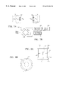
- FIG. 6 is a view of a load cell shown in FIG. 3 .
- FIGS. 7A and 7B show diagrams of the electrical connection of strain-gauge elements shown in FIG. 6 .
- FIG. 8A is a side perspective view of a load cell as an alternate to the one shown in FIG. 6, in accord with an alternate embodiment of the present invention.
- FIG. 8B is a top down view of the load cell shown in FIG. 8 A.
- FIG. 9 is a graph depicting weight in pound, versus data sample number to demonstrate a data stream produced in accord with the present invention.
- FIG. 10 shows the use of a pressure gauge in the hydraulic system for sensing force.
- a forklift truck 10 has a mast assembly 12 comprising a generally U-shaped bottom mast section 14 having a pair of spaced-apart and parallel hollow legs 16 and 18 secured to a base member 20 extending therebetween.
- a longitudinal axis 22 of the bottom mast section 14 is disposed substantially vertical to a chassis of the forklift truck 10 .
- a top mast portion 24 is coupled to a hydraulic ram 32 .
- the ram has a cylinder 34 , mounted on the base member 20 , and a piston rod 36 , connected to an axle 30 .
- the hydraulic ram 32 positions the top mast section 24 , with respect to the bottom mast section 14 , between extended and retracted positions.
- a carriage assembly 38 includes a plate-like member 40 that extends parallel to base member 20 . Brackets 42 and 44 are secured to the member 40 . Brackets 42 and 44 extend from member 40 in a direction transverse to base member 20 . A fork 13 , or other load bearing member, extends from member 40 , in a direction opposite to brackets 42 and 44 -and opposite to transverse member 20 .
- Carriage support chains 54 and 56 pass over respective sprockets 58 and 60 which are supported by axle 30 .
- Each support chain 54 and 56 is secured, at one end, to the carriage assembly 38 .
- the remaining end of each support chain 54 and 56 is secured to an anchor member 62 .
- each chain 54 and 56 forms two spaced-apart and opposing portions, shown in FIG. 2 with respect to chain 54 as anchor portion 54 a and load portion 54 b .
- Anchor portion 54 a extends from anchor member 62 and terminates proximate to longitudinal axis 22 .
- Load portion 54 b extends from carriage assembly 38 and terminates proximate to longitudinal axis 22 .
- the anchor member 62 is attached to the bottom mast section 14 , on the side opposite to the carriage assembly 38 .
- the anchor member 62 comprises an L-section girder secured (e.g. by welding) to the legs 16 and 18 , so that a flange 64 of the anchor member 62 projects horizontally outward past the plane of the legs 16 and 18 .
- Eye-bolts 66 and 68 are secured to the ends of the chains 54 and 56 by respective pins 70 and 72 .
- the shanks of the eye-bolts 66 and 68 pass through respective clearance holes 74 and 76 in the flange 64 .
- Load cell transducers 78 and 80 are fitted over the shanks of the eye-bolts 66 and 68 between the underside of the flange 64 and respective washers 82 and 84 and retaining nuts 86 and 88 .
- the pull on the chains 54 and 56 exerts compressive forces on the load cell transducers 78 and 80 .
- chain 54 includes a plurality of links 54 c , each of which includes two rollers 54 d and 54 e separated by a distance, defining a pitch P.
- a force F p is imparted upon the sprocket-wheel 58 which loads both the anchor and load portions 54 a and 54 b of the chain 54 .
- the effective force, F ANCHOR placed upon the anchor portion 54 , and sensed by the load cell transducer 78 , may be defined as follows:
- R A is the distance between the center of anchor portion 54 a and the axis of rotation 65 of the sprocket wheel 58 , measured parallel to the axis 63 .
- R L is the distance between the center of load portion 54 b and the axis of rotation 65 of the sprocket wheel 58 , measured parallel to the axis 63 . Both R A and R L , however, vary while the carriage 38 is moved along the mast 12 due to the geometry of the chain 54 .
- R A , R L or both may be equal to the radius of sprocket wheel 58 , R S , plus the radius of the roller 54 d or 54 e , R R , defining a maximum radius R M .
- R A , R L or both may measure distance R N , which is less than R M , defining a minimum distance.
- the minimum distance R N is simply R S plus R D , the distance from the center of the link to the edge of the sprocket wheel 58 .
- R A and R L each moves cyclically between distances R M and R N .
- equation (1) it can be seen that this cyclical change in measurement for R A , R L causes the actual force upon anchor portion 54 a to differ from the force disposed upon load portion 54 b , unless R A equals R L , i.e., the ratio of R L /R A is a constant. This introduces an error in the load sensed by the load cell transducer 78 .
- an equalizer system is employed which ensures that R A equals R L so that the chain 54 hangs symmetrically about sprocket-wheel 58 , with each link 54 c subtending a predetermined portion of the circumference of the sprocket-wheel 58 . It was determined that the aforementioned symmetry is present when the relative geometry of the sprocket-wheel 58 and the chain 54 is defined as follows:
- the equalizer system would include providing the chain 54 and the sprocket-wheel 58 with the physical characteristics so that equation (2) is satisfied. This abrogates measurement errors in the load cell transducers by ensuring the force present on the anchor system portion 54 a is substantially similar to the force on the load portion 54 b.
- equation (1) effectively becomes:
- One manner in which to sense the rotational movement of the sprocket-wheel 58 is to provide indicia upon sprocket-wheel 58 demarking increments of 2 ⁇ .
- a detector could be positioned to sense the indicia.
- the angular movement of 2 ⁇ in the sprocket-wheel 58 corresponds to 2P of movement of the carriage in a direction parallel to gravity, where P is the pitch defined by each link in the chain 54 .
- P the pitch defined by each link in the chain 54 .
- One manner in which to detect 2P of relative movement is to attach a proximity sensor to one of the mast sections 14 or 24 so as to be in data communication with the remaining mast section 14 or 24 .
- the proximity sensor is an optical detector 67 attached to the lower mast portion 14 so as to be selectively placed in data communication with an optically responsive strip 69 attached to the carriage 38 .
- the strip 69 is chosen so that it has a length l equal to multiples of 2P. For example, the length l may be equal to 2P, 4P, 6P, etc.
- the strip 69 is attached to platelike member 40 so that its longitudinal axis extends parallel to axis 22 . In this fashion, load measurements could occur during movement of the sprocket-wheel through angles 2 ⁇ , 4 ⁇ , 6 ⁇ , etc.
- detector 67 is a photoelectric sensor sold by Honeywell under catalog number CP18LDNL2.
- any type of optically responsive strip may be employed, however, it is preferred that optically responsive strip 69 is reflective sheeting manufactured by 3M Company, St. Paul, Minn. and sold under the catalog number 580-10.
- the detector 67 is positioned to sense the strip at a point about 12 to 15 inches from base member 20 . At this point, the acceleration of the carriage has ceased.
- detector 67 has been described as employing a photoelectric detector, the detector 67 may include a magnetic sensor, such as the type sold by Honeywell under the designation SR3 series. As a result, strip 69 would comprise of a magnetic stripping.
- load cells 78 and 80 each is preferably a torsional sensing load cell 500 as shown in FIG. 6, and as fully disclosed in pending U.S. application for patent, identified as Ser. No. 08/942,314 filed Oct. 1, 1997 and assigned to the assignee of the present invention, herein incorporated by reference.
- load cell 500 consists of a body member 560 that has a split to form a gap 550 .
- An upper loading platform 520 is attached to one end 565 of the gap and a bottom loading platform 540 is attached to the other end 567 of the gap.
- a first transducer 502 is disposed on body member 560 and a second transducer (not shown) is disposed on body member 560 in diametrically opposed relation to transducer 502 .
- An axial opening 530 passes through the load cell.
- load cells 78 and 80 are mounted by fitting eye-bolts 66 and 68 through their respective openings 530 .
- the respective upper loading platforms 520 support flange 64 .
- the respective bottom loading platforms 540 bear upon washers 82 and 84 .
- body member 560 experiences a torsional force.
- the transducers mounted to the body member sense this torsional stress.
- a 5,000 lb. capacity forklift would comprise a pair of 3,000 lb. rated load cells. Each load cell would have a diameter (D) of 2 inches and a height (H) of 2 inches.
- Transducer 502 is shown with diametrically opposed transducer 504 , both mounted on body member 560 .
- Each transducer comprises a pair of resistive strain-gauge elements; transducer 502 comprises elements R TA and R CA having a common connection, while transducer 504 comprises elements R TB and R CB having a common connection.
- FIG. 7B shows the transducers coupled in a standard Wheatstone bridge configuration 112 .
- the common connection between R TA and R CA is coupled to a drive voltage V D
- the common connection between R TB and R CB is coupled to ground potential.
- the voltages at output nodes 116 and 118 vary depending on the strain (in this case torsional strain) sensed by the strain-gauge elements, which in turn depends on the load experienced by load cells 78 , 80 .
- the voltages are fed into processing circuitry 120 , so as to transmit load measurements to the circuitry.
- Detector 67 (FIG. 2) is coupled to the processing circuitry and controls it such that load measurements are accumulated only for a predetermined amount of rotational movement of sprocket wheel 58 .
- the information generated is then supplied to a visual display device 122 .
- the piston 32 raises carriage 38 .
- the detector 67 passes strip 69 , it impinges a beam thereupon which is reflected back to the detector 67 . So long as the detector 67 senses the beam, the proximity sensor 71 transmits a signal to the processing circuity 120 , allowing the same to accumulate data samples corresponding to the load sensed. After the detector 67 has passed strip 69 , the beam is no longer detected thereby, causing the proximity sensor to cease the accumulation of data by the processing circuitry 120 .
- the processing circuitry 120 creates a data stream 121 from the load data, with each of the data samples being associated with a unique increment of the stream. The data samples are then summed and the average load sensed is calculated. The weight of the load is made visible of the visual display 122 .
- compressive load cell transducers may include a generally spool-shaped body 200 having a central cylindrical portion 202 disposed between end portion 204 and 206 . Each of the end portions 204 and 206 are a greater diameter than that of the central portion 202 .
- An axial bore 208 has a diameter such that the shank of eye-bolts 66 and 68 may pass freely therethrough.
- strain-gauge element there is at least one resistive strain-gauge element affixed to the outer surface of portion 202 such that the element is responsive to compressive forces applied between the end surfaces 206 and 208 of the load cell transducer.
- two strain-gauge elements 210 and 212 are affixed symmetrically to the central portion 202 so as to be responsive to compressive forces.
- Two further elements 214 and 216 are affixed so as to be affected by compressive forces as defined by Poisson's ratio.
- the strain-gauge members 210 , 212 , 214 and 216 are electrically connected as discussed above with respect to FIGS. 7A and 7B.
- tension load cells may be employed in lieu of compressive load cells.
- tension load cell is sold by Industrial Electronic
- the hydraulic ram 32 includes a hydraulic pump 610 which pumps hydraulic fluid between a reservoir 612 and the cylinder 34 to raise or lower the piston rod 36 .
- a hydraulic pump 610 which pumps hydraulic fluid between a reservoir 612 and the cylinder 34 to raise or lower the piston rod 36 .
- variations in the tension in chain 54 ( 56 ) will be transmitted to the piston rod 36 by virtue of the mechanical connection of the sprocket-wheel 58 and the chain. Therefore, the pressure of the hydraulic fluid will vary in the manner as discussed in connection with Eqn. 1.
- an alternative to the use of force measurements provided by load cells 78 and 80 is the use of pressure readings taken by a pressure sensor 602 which can be accumulated in processor 120 and averaged. A subsequent conversion, namely multiplication by the cross-sectional area of cylinder 34 , of the averaged pressure readings is then made to arrive at the corresponding weight of the load.
- W is the weight of the load
- A is the effective area of piston 36 .
- g is the acceleration due to gravity
- k is a factor ( ⁇ 1) that varies with the geometry of roller 58 .
- the coefficient of friction term B is desirable to determine. This allows the forklift to be operated at different velocities while still producing accurate weight measurements.
- the coefficient B is computed first by taking a pressure reading while lifting a load at one constant velocity and taking another pressure reading while lifting the same load at another constant velocity.
- the ratio of the difference between pressure readings to the difference between lifting velocities is the coefficient of friction B.
- the means by which the weight of the load is sensed is not crucial to the invention.
- a direct measurement such as the use of transducers 78 and 80 coupled to the chain 54 can be used.
- an indirect measurement such as the pressure readings from the hydraulic system can is equally effective. It is important only that the force which is sensed reflects the variations in detected load caused by the sprocket-wheel and chain combination as discussed in connection with Egn. 1.
Landscapes
- Physics & Mathematics (AREA)
- General Physics & Mathematics (AREA)
- Forklifts And Lifting Vehicles (AREA)
Abstract
Description


Claims (10)
Priority Applications (1)
| Application Number | Priority Date | Filing Date | Title |
|---|---|---|---|
| US09/351,865 US6232566B1 (en) | 1999-07-12 | 1999-07-12 | Apparatus in a lifting device for reducing error in weight measurements |
Applications Claiming Priority (1)
| Application Number | Priority Date | Filing Date | Title |
|---|---|---|---|
| US09/351,865 US6232566B1 (en) | 1999-07-12 | 1999-07-12 | Apparatus in a lifting device for reducing error in weight measurements |
Publications (1)
| Publication Number | Publication Date |
|---|---|
| US6232566B1 true US6232566B1 (en) | 2001-05-15 |
Family
ID=23382749
Family Applications (1)
| Application Number | Title | Priority Date | Filing Date |
|---|---|---|---|
| US09/351,865 Expired - Fee Related US6232566B1 (en) | 1999-07-12 | 1999-07-12 | Apparatus in a lifting device for reducing error in weight measurements |
Country Status (1)
| Country | Link |
|---|---|
| US (1) | US6232566B1 (en) |
Cited By (14)
| Publication number | Priority date | Publication date | Assignee | Title |
|---|---|---|---|---|
| US20030155564A1 (en) * | 2002-02-15 | 2003-08-21 | Fmc Technologies, Inc. | Anchor chain load measurement arrangement |
| US20040094336A1 (en) * | 2001-03-09 | 2004-05-20 | Axel Weyer | Method and device for weighing the content of a metallurgical vessel, particularly the content of a distributing launder in steel continuous casting installations |
| US20050051367A1 (en) * | 2003-08-26 | 2005-03-10 | Hagen Martin H. | Bin lifting and weigh scale arrangement |
| US20050092530A1 (en) * | 2003-10-30 | 2005-05-05 | Rice Thomas S. | Apparatus and method for weighting objects on a fork lift truck |
| US20050132818A1 (en) * | 2003-09-05 | 2005-06-23 | Gerald Simons | Device for leaf chain load cell |
| WO2006128454A1 (en) * | 2005-06-03 | 2006-12-07 | Torben Winther Hansen | Method of weight determination of a load carried by a lifter of a lifting device and weighing device |
| EP1953114A3 (en) * | 2007-02-01 | 2010-01-27 | STILL WAGNER GmbH | Industrial truck with a hydraulically liftable load pick-up |
| US20110206483A1 (en) * | 2010-02-19 | 2011-08-25 | Gauthier Steven | Weight sensing method and apparatus for forklifts |
| EP2023099A3 (en) * | 2007-07-30 | 2011-08-31 | Soehnle Professional GmbH & Co. KG | Device for determining a force on a pulling device |
| CN108020303A (en) * | 2017-12-21 | 2018-05-11 | 沪东中华造船(集团)有限公司 | A kind of load-bearing ground pier and measuring and operating method that can monitor segmentation block weight in real time |
| US20200198614A1 (en) * | 2018-12-20 | 2020-06-25 | Bendix Commercial Vehicle Systems Llc | System and method for determining status of a brake spring |
| WO2022231805A1 (en) * | 2021-04-27 | 2022-11-03 | Illinois Tool Works Inc. | Forklift truck sensor scale |
| US11503754B2 (en) * | 2016-12-28 | 2022-11-22 | Cnh Industrial America Llc | Process for weighing the harvested crop stored in a tank on a harvesting machine |
| US12612294B2 (en) | 2021-04-27 | 2026-04-28 | Illinois Tool Works Inc. | Forklift truck sensor scale |
Citations (11)
| Publication number | Priority date | Publication date | Assignee | Title |
|---|---|---|---|---|
| US2582886A (en) | 1948-03-13 | 1952-01-15 | Baldwin Lima Hamilton Corp | Differential load weighing device |
| US2813709A (en) | 1954-01-06 | 1957-11-19 | Ohio Commw Eng Co | Strain gauge load indicator |
| US4212360A (en) | 1977-10-20 | 1980-07-15 | Pye (Electronics Products) Limited | Load measuring arrangements for fork lift trucks or the like |
| US5139101A (en) | 1991-04-10 | 1992-08-18 | Wray-Tech Instruments, Inc. | Hydraulic control system for weighing and two-way valve therefor |
| US5195418A (en) | 1991-04-10 | 1993-03-23 | Wray-Tech Instruments, Inc. | Hydraulic control system for weighting and two-way valve therefor |
| US5461933A (en) | 1994-02-04 | 1995-10-31 | Acutus Industries, Inc. | Shear web load cell having thermal compensation |
| US5509293A (en) * | 1994-12-20 | 1996-04-23 | Caterpillar Inc. | Dynamic payload monitor |
| US5666295A (en) * | 1996-01-05 | 1997-09-09 | Sentek Products | Apparatus and method for dynamic weighing of loads in hydraulically operated lifts |
| US5783755A (en) | 1997-03-04 | 1998-07-21 | Gagetek Company | Lifting device employing an equalizer system to reduce weight measurement error |
| US5824963A (en) * | 1997-03-04 | 1998-10-20 | Gagetek Company | Lifting device employing a weight integrative weighing system |
| US5925832A (en) * | 1997-10-01 | 1999-07-20 | Gagetek Company | Torsional sensing load cell |
-
1999
- 1999-07-12 US US09/351,865 patent/US6232566B1/en not_active Expired - Fee Related
Patent Citations (12)
| Publication number | Priority date | Publication date | Assignee | Title |
|---|---|---|---|---|
| US2582886A (en) | 1948-03-13 | 1952-01-15 | Baldwin Lima Hamilton Corp | Differential load weighing device |
| US2813709A (en) | 1954-01-06 | 1957-11-19 | Ohio Commw Eng Co | Strain gauge load indicator |
| US4212360A (en) | 1977-10-20 | 1980-07-15 | Pye (Electronics Products) Limited | Load measuring arrangements for fork lift trucks or the like |
| US5139101A (en) | 1991-04-10 | 1992-08-18 | Wray-Tech Instruments, Inc. | Hydraulic control system for weighing and two-way valve therefor |
| US5195418A (en) | 1991-04-10 | 1993-03-23 | Wray-Tech Instruments, Inc. | Hydraulic control system for weighting and two-way valve therefor |
| US5287885A (en) | 1991-04-10 | 1994-02-22 | Wray-Tech Instruments, Inc. | Hydraulic control system for weighing and two-way valve therefor |
| US5461933A (en) | 1994-02-04 | 1995-10-31 | Acutus Industries, Inc. | Shear web load cell having thermal compensation |
| US5509293A (en) * | 1994-12-20 | 1996-04-23 | Caterpillar Inc. | Dynamic payload monitor |
| US5666295A (en) * | 1996-01-05 | 1997-09-09 | Sentek Products | Apparatus and method for dynamic weighing of loads in hydraulically operated lifts |
| US5783755A (en) | 1997-03-04 | 1998-07-21 | Gagetek Company | Lifting device employing an equalizer system to reduce weight measurement error |
| US5824963A (en) * | 1997-03-04 | 1998-10-20 | Gagetek Company | Lifting device employing a weight integrative weighing system |
| US5925832A (en) * | 1997-10-01 | 1999-07-20 | Gagetek Company | Torsional sensing load cell |
Non-Patent Citations (1)
| Title |
|---|
| Denco Sales Co. data sheet, "Scotchlite Reflective Sheeting", Mar. 31, 1995. |
Cited By (24)
| Publication number | Priority date | Publication date | Assignee | Title |
|---|---|---|---|---|
| US20040094336A1 (en) * | 2001-03-09 | 2004-05-20 | Axel Weyer | Method and device for weighing the content of a metallurgical vessel, particularly the content of a distributing launder in steel continuous casting installations |
| US20030155564A1 (en) * | 2002-02-15 | 2003-08-21 | Fmc Technologies, Inc. | Anchor chain load measurement arrangement |
| US6925890B2 (en) * | 2002-02-15 | 2005-08-09 | Fmc Technologies, Inc. | Anchor chain load measurement arrangement |
| US20050051367A1 (en) * | 2003-08-26 | 2005-03-10 | Hagen Martin H. | Bin lifting and weigh scale arrangement |
| US7211747B2 (en) * | 2003-08-26 | 2007-05-01 | Shred-Tech Corporation | Bin lifting and weigh scale arrangement |
| US7082845B2 (en) * | 2003-09-05 | 2006-08-01 | Weigh Point Incorporated | Device for leaf chain load cell |
| US20050132818A1 (en) * | 2003-09-05 | 2005-06-23 | Gerald Simons | Device for leaf chain load cell |
| US20050092530A1 (en) * | 2003-10-30 | 2005-05-05 | Rice Thomas S. | Apparatus and method for weighting objects on a fork lift truck |
| US7026557B2 (en) * | 2003-10-30 | 2006-04-11 | Mettler-Toledo | Apparatus and method for weighting objects on a fork lift truck |
| WO2006128454A1 (en) * | 2005-06-03 | 2006-12-07 | Torben Winther Hansen | Method of weight determination of a load carried by a lifter of a lifting device and weighing device |
| US20080314649A1 (en) * | 2005-06-03 | 2008-12-25 | Torben Winther Hansen | Method of Weight Determination of a Load Carried by a Lifter of a Lifting Device and Weighing Device |
| EA011053B1 (en) * | 2005-06-03 | 2008-12-30 | Торбен Винтер Хансен | Method of weight determination of a load carried by a lifter of a lifting device and weighing device |
| CN101223424B (en) * | 2005-06-03 | 2011-08-10 | 托尔文·温瑟·汉森 | Method and weighing device for determining the weight of a load carried by a lifter of a lifting device |
| US7795547B2 (en) | 2005-06-03 | 2010-09-14 | Torben Winther Hansen | Method of weight determination of a load carried by a lifter of a lifting device and weighing device |
| EP1953114A3 (en) * | 2007-02-01 | 2010-01-27 | STILL WAGNER GmbH | Industrial truck with a hydraulically liftable load pick-up |
| EP2023099A3 (en) * | 2007-07-30 | 2011-08-31 | Soehnle Professional GmbH & Co. KG | Device for determining a force on a pulling device |
| US20110206483A1 (en) * | 2010-02-19 | 2011-08-25 | Gauthier Steven | Weight sensing method and apparatus for forklifts |
| US8779306B2 (en) * | 2010-02-19 | 2014-07-15 | Methode Electronics, Inc. | Weight sensing method and apparatus for forklifts |
| US11503754B2 (en) * | 2016-12-28 | 2022-11-22 | Cnh Industrial America Llc | Process for weighing the harvested crop stored in a tank on a harvesting machine |
| CN108020303A (en) * | 2017-12-21 | 2018-05-11 | 沪东中华造船(集团)有限公司 | A kind of load-bearing ground pier and measuring and operating method that can monitor segmentation block weight in real time |
| US20200198614A1 (en) * | 2018-12-20 | 2020-06-25 | Bendix Commercial Vehicle Systems Llc | System and method for determining status of a brake spring |
| US10919511B2 (en) * | 2018-12-20 | 2021-02-16 | Bendix Commercial Vehicle Systems Llc | System and method for determining status of a brake spring |
| WO2022231805A1 (en) * | 2021-04-27 | 2022-11-03 | Illinois Tool Works Inc. | Forklift truck sensor scale |
| US12612294B2 (en) | 2021-04-27 | 2026-04-28 | Illinois Tool Works Inc. | Forklift truck sensor scale |
Similar Documents
| Publication | Publication Date | Title |
|---|---|---|
| US6232566B1 (en) | Apparatus in a lifting device for reducing error in weight measurements | |
| US5824963A (en) | Lifting device employing a weight integrative weighing system | |
| US3938603A (en) | Constant moment weigh scale with floating flexure beam | |
| US5666295A (en) | Apparatus and method for dynamic weighing of loads in hydraulically operated lifts | |
| US4260034A (en) | Conveyor scale | |
| CA1076617A (en) | Flexure scale | |
| US5090493A (en) | Load cells and scales therefrom | |
| US5783755A (en) | Lifting device employing an equalizer system to reduce weight measurement error | |
| US11092477B2 (en) | Planar load cell assembly | |
| US20070074560A1 (en) | Loadcell live idler platform scale | |
| US9617116B2 (en) | Load measuring device for an elevator installation | |
| US3724575A (en) | Force detecing and evaluating apparatus | |
| WO1999017087A1 (en) | Torsional sensing load cell | |
| US3474875A (en) | Strain-gaged treadle scales | |
| US3103984A (en) | Weighing device | |
| US3603416A (en) | Weighing apparatus for belt conveyor | |
| EP3531086B1 (en) | Conveyor system with weighing capability | |
| US20240295430A1 (en) | Method for measuring the load on a vehicle axle with temperature compensation using a strain gauge (variants) | |
| USRE32003E (en) | Constant moment weigh scale with floating flexure beam | |
| US5239137A (en) | Method for calibrating sensors arranged in pairs on loaded structural parts | |
| JP3444810B2 (en) | Seat weight measuring device | |
| US4757867A (en) | Single load cell weighing systems | |
| WO1997004289A1 (en) | Strain measuring devices, and monitoring of vehicle container loads | |
| WO2011056865A1 (en) | Improvements relating to load cells | |
| US20080041638A1 (en) | Low Profile Load Cell |
Legal Events
| Date | Code | Title | Description |
|---|---|---|---|
| AS | Assignment |
Owner name: GAGETEK TECHNOLOGIES, LLC, CALIFORNIA Free format text: ASSIGNMENT OF ASSIGNORS INTEREST;ASSIGNOR:BRUNS, ROBERT W.;REEL/FRAME:010137/0257 Effective date: 19990701 |
|
| AS | Assignment |
Owner name: GAGE TEK TECHNOLOGIES HOLDINGS COMPANY, CALIFORNIA Free format text: ASSIGNMENT OF ASSIGNORS INTEREST;ASSIGNOR:GAGE TEK TECHNOLOGIES, LLC;REEL/FRAME:011651/0332 Effective date: 20010306 |
|
| AS | Assignment |
Owner name: GAGETEK TECHNOLOGIES HOLDINGS COMPANY, CALIFORNIA Free format text: ASSIGNMENT OF ASSIGNORS INTEREST;ASSIGNOR:GAGETEK TECHNOLOGIES, LLC;REEL/FRAME:011796/0129 Effective date: 20010306 |
|
| REMI | Maintenance fee reminder mailed | ||
| FEPP | Fee payment procedure |
Free format text: PETITION RELATED TO MAINTENANCE FEES FILED (ORIGINAL EVENT CODE: PMFP); ENTITY STATUS OF PATENT OWNER: SMALL ENTITY |
|
| FEPP | Fee payment procedure |
Free format text: PETITION RELATED TO MAINTENANCE FEES GRANTED (ORIGINAL EVENT CODE: PMFG); ENTITY STATUS OF PATENT OWNER: SMALL ENTITY |
|
| REIN | Reinstatement after maintenance fee payment confirmed | ||
| LAPS | Lapse for failure to pay maintenance fees |
Free format text: PATENT EXPIRED FOR FAILURE TO PAY MAINTENANCE FEES (ORIGINAL EVENT CODE: EXP.); ENTITY STATUS OF PATENT OWNER: SMALL ENTITY |
|
| FP | Lapsed due to failure to pay maintenance fee |
Effective date: 20050515 |
|
| FPAY | Fee payment |
Year of fee payment: 4 |
|
| SULP | Surcharge for late payment | ||
| PRDP | Patent reinstated due to the acceptance of a late maintenance fee |
Effective date: 20050811 |
|
| AS | Assignment |
Owner name: BRUNS, ROBERT W., CALIFORNIA Free format text: ASSIGNMENT OF ASSIGNORS INTEREST;ASSIGNOR:GAGETEK TECHNOLOGIES HOLDING COMPANY;REEL/FRAME:020897/0713 Effective date: 20080414 |
|
| REMI | Maintenance fee reminder mailed | ||
| FPAY | Fee payment |
Year of fee payment: 8 |
|
| SULP | Surcharge for late payment |
Year of fee payment: 7 |
|
| REMI | Maintenance fee reminder mailed | ||
| LAPS | Lapse for failure to pay maintenance fees | ||
| STCH | Information on status: patent discontinuation |
Free format text: PATENT EXPIRED DUE TO NONPAYMENT OF MAINTENANCE FEES UNDER 37 CFR 1.362 |
|
| FP | Lapsed due to failure to pay maintenance fee |
Effective date: 20130515 |