US6227798B1 - Turbine nozzle segment band cooling - Google Patents
Turbine nozzle segment band cooling Download PDFInfo
- Publication number
- US6227798B1 US6227798B1 US09/451,279 US45127999A US6227798B1 US 6227798 B1 US6227798 B1 US 6227798B1 US 45127999 A US45127999 A US 45127999A US 6227798 B1 US6227798 B1 US 6227798B1
- Authority
- US
- United States
- Prior art keywords
- intake duct
- vane
- flange portion
- outer band
- vanes
- Prior art date
- Legal status (The legal status is an assumption and is not a legal conclusion. Google has not performed a legal analysis and makes no representation as to the accuracy of the status listed.)
- Expired - Lifetime
Links
Images


Classifications
-
- F—MECHANICAL ENGINEERING; LIGHTING; HEATING; WEAPONS; BLASTING
- F01—MACHINES OR ENGINES IN GENERAL; ENGINE PLANTS IN GENERAL; STEAM ENGINES
- F01D—NON-POSITIVE DISPLACEMENT MACHINES OR ENGINES, e.g. STEAM TURBINES
- F01D25/00—Component parts, details, or accessories, not provided for in, or of interest apart from, other groups
- F01D25/08—Cooling; Heating; Heat-insulation
- F01D25/12—Cooling
-
- F—MECHANICAL ENGINEERING; LIGHTING; HEATING; WEAPONS; BLASTING
- F01—MACHINES OR ENGINES IN GENERAL; ENGINE PLANTS IN GENERAL; STEAM ENGINES
- F01D—NON-POSITIVE DISPLACEMENT MACHINES OR ENGINES, e.g. STEAM TURBINES
- F01D5/00—Blades; Blade-carrying members; Heating, heat-insulating, cooling or antivibration means on the blades or the members
- F01D5/12—Blades
- F01D5/14—Form or construction
- F01D5/18—Hollow blades, i.e. blades with cooling or heating channels or cavities; Heating, heat-insulating or cooling means on blades
-
- F—MECHANICAL ENGINEERING; LIGHTING; HEATING; WEAPONS; BLASTING
- F01—MACHINES OR ENGINES IN GENERAL; ENGINE PLANTS IN GENERAL; STEAM ENGINES
- F01D—NON-POSITIVE DISPLACEMENT MACHINES OR ENGINES, e.g. STEAM TURBINES
- F01D9/00—Stators
- F01D9/02—Nozzles; Nozzle boxes; Stator blades; Guide conduits, e.g. individual nozzles
- F01D9/04—Nozzles; Nozzle boxes; Stator blades; Guide conduits, e.g. individual nozzles forming ring or sector
- F01D9/041—Nozzles; Nozzle boxes; Stator blades; Guide conduits, e.g. individual nozzles forming ring or sector using blades
-
- F—MECHANICAL ENGINEERING; LIGHTING; HEATING; WEAPONS; BLASTING
- F05—INDEXING SCHEMES RELATING TO ENGINES OR PUMPS IN VARIOUS SUBCLASSES OF CLASSES F01-F04
- F05D—INDEXING SCHEME FOR ASPECTS RELATING TO NON-POSITIVE-DISPLACEMENT MACHINES OR ENGINES, GAS-TURBINES OR JET-PROPULSION PLANTS
- F05D2230/00—Manufacture
- F05D2230/20—Manufacture essentially without removing material
- F05D2230/21—Manufacture essentially without removing material by casting
-
- F—MECHANICAL ENGINEERING; LIGHTING; HEATING; WEAPONS; BLASTING
- F05—INDEXING SCHEMES RELATING TO ENGINES OR PUMPS IN VARIOUS SUBCLASSES OF CLASSES F01-F04
- F05D—INDEXING SCHEME FOR ASPECTS RELATING TO NON-POSITIVE-DISPLACEMENT MACHINES OR ENGINES, GAS-TURBINES OR JET-PROPULSION PLANTS
- F05D2240/00—Components
- F05D2240/10—Stators
- F05D2240/12—Fluid guiding means, e.g. vanes
- F05D2240/128—Nozzles
-
- F—MECHANICAL ENGINEERING; LIGHTING; HEATING; WEAPONS; BLASTING
- F05—INDEXING SCHEMES RELATING TO ENGINES OR PUMPS IN VARIOUS SUBCLASSES OF CLASSES F01-F04
- F05D—INDEXING SCHEME FOR ASPECTS RELATING TO NON-POSITIVE-DISPLACEMENT MACHINES OR ENGINES, GAS-TURBINES OR JET-PROPULSION PLANTS
- F05D2260/00—Function
- F05D2260/20—Heat transfer, e.g. cooling
- F05D2260/201—Heat transfer, e.g. cooling by impingement of a fluid
-
- Y—GENERAL TAGGING OF NEW TECHNOLOGICAL DEVELOPMENTS; GENERAL TAGGING OF CROSS-SECTIONAL TECHNOLOGIES SPANNING OVER SEVERAL SECTIONS OF THE IPC; TECHNICAL SUBJECTS COVERED BY FORMER USPC CROSS-REFERENCE ART COLLECTIONS [XRACs] AND DIGESTS
- Y02—TECHNOLOGIES OR APPLICATIONS FOR MITIGATION OR ADAPTATION AGAINST CLIMATE CHANGE
- Y02T—CLIMATE CHANGE MITIGATION TECHNOLOGIES RELATED TO TRANSPORTATION
- Y02T50/00—Aeronautics or air transport
- Y02T50/60—Efficient propulsion technologies, e.g. for aircraft
Definitions
- This invention relates to aircraft gas turbine engine turbine nozzle segments and, more particularly, to cooling of bands between which airfoils of the segments are mounted.
- HPT high pressure turbine
- LPT low pressure turbine
- Each LPT turbine nozzle includes a plurality of circumferentially spaced apart stationary nozzle vanes supported between radially outer and inner bands.
- Each turbine rotor stage includes a plurality of circumferentially spaced apart rotor blades extending radially outwardly from a rotor disk which carries torque developed during operation.
- the LPT nozzles are typically formed in arcuate segments having a plurality of vanes integrally joined between corresponding segments of the outer and inner bands. Each nozzle segment is supported at its radially outer end by a flange bolted to an annular outer casing. Each vane has a cooled hollow airfoil disposed between radially inner and outer band panels which form the inner and outer bands, a flange portion along a mid portion of the outer band panel, and a cooling air intake duct for directing cooling air through an opening in the flange portion into the hollow interior or cooling circuit of the airfoil.
- the intake duct has a 90 degree bend between an axially forward intake duct inlet and an axially aft and radially inward intake duct outlet.
- the 90 degree bend curves radially inwardly from the opening which in the flange portion toward the hollow airfoil and axially as it extends aft and ends at an intake duct outlet.
- the airfoil, inner and outer band portions, flange portion, and intake duct are typically cast together such that each vane is a single casting.
- the vanes are brazed together along interfaces of the flange segments, inner band panels, and outer band panels to form the nozzle segment.
- the intake duct has a significant amount of convective cooling which it conducts to the band locally but not to the middle of the band between the intake ducts or airfoils. This region of the band between intake ducts operates significantly hotter.
- Cooling schemes that use cooling air from the compressor enhance band cooling for a given amount of cooling flow but also have significant negative effects on engine performance. Impingement baffles, film holes, pin banks and trailing edge holes are all cooling features that have been used in production engines for cooling HPT nozzle bands. Cooling holes disposed through the flange have been used to direct cooling air from a cooling air plenum onto the braze joint along the interface between the outer band panels of the flange portions of an LPT nozzle band.
- Location of the cooling holes that are disposed through the flange include avoiding obstruction by bolt heads in a flange joint with the engine casing and the cooling air jet from the holes travels far before impinging the band at highly stressed areas further aft of the flange.
- LPT band cooling It is highly desirable to improve LPT band cooling while minimizing the amount of cooling flow used to do so. It is also highly desirable to improve LPT band cooling to prevent cracking along brazed joints to extend the life of the part and time between repairs of the nozzle segments and vane assemblies. It is desirable to have the impingement jet strike the band farther aft than currently possible without increasing the distance the jet target travels to impingement, thus, minimizing jet velocity decay and improving the convection over the band from the jet. It is also desirable to allow more flexibility in choosing impingement jet location, orientation and angle to the band surface, thus, permitting maximization of cooling effect.
- a gas turbine engine nozzle segment includes at least two circumferentially adjacent vanes joined together along an interface between the vanes.
- Each of the vanes includes a hollow airfoil disposed between radially inner and outer band panels and a cooling air intake duct leading to a hollow interior of the airfoil for directing cooling air into the hollow interior.
- the intake duct has a duct wall protruding radially outward from the outer band panel and at least one impingement cooling hole disposed through the intake duct wall and circumferentially and radially inwardly angled.
- a flange portion extends circumferentially along a mid portion of the outer band panel and an opening in the flange portion is in fluid communication with the intake duct.
- the hollow airfoil, radially inner and outer band panels, intake duct wall, and flange portion are integrally formed and preferably integrally cast such that the vane is a single piece integrally cast vane.
- FIG. 1 is a schematic cross-sectional view illustration of gas turbine engine high and low pressure turbine sections with an exemplary embodiment of a low pressure turbine nozzle assembly of the present invention.
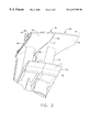
- FIG. 2 is a perspective view illustration of a nozzle segment of the nozzle assembly in FIG. 1 from a radially inward point looking radially outwardly and axially aftwardly.
- FIG. 3 is a perspective view illustration of a radially outer band of the nozzle segment in FIG. 2 .
- FIG. 4 is a schematic crosss-sectional view illustration of an impingement cooling hole through a wall of an intake duct taken through lines 4 — 4 of a radially outer portion of the nozzle segment in FIG. 3 .
- FIG. 5 is a cut-a-way perspective view illustration of the intake duct in FIGS. 1 and 4 .
- FIG. 1 Illustrated in FIG. 1, is a portion of an aircraft gas turbine engine hot section, generally designated 2 , having an axial extending centerline 6 about which runs through a combustor 10 , a high pressure turbine (HPT) 12 , and a first stage of a low pressure turbine (LPI) 14 .
- Circumscribed about centerline 6 is high pressure casing 15 around the combustor 10 and the HPT 12 and a low pressure casing 17 around the LPI 14 .
- Air is compressed in a compressor (not shown) and mixed with fuel in the combustor 10 to produce a high energy hot gas stream 11 .
- Aft of the combustor 10 is a HPT nozzle 18 which directs the hot gas stream 11 from the combustor to HPT blades 20 mounted on a first periphery 22 around a HPT disk 26 .
- the hot gas stream 11 is then flowed through a LPT nozzle assembly 30 having an assembly of arcuate LPT nozzle segments 32 , illustrating an exemplary embodiment of the present invention, which directs the hot gas stream to LPT blades 27 mounted on a second periphery 28 around a LPT disk 29 .
- FIG. 2 One of circumferentially adjoining nozzle segments 32 is illustrated in FIG. 2 .
- Each of the nozzle segments 32 includes two or more circumferentially spaced apart nozzle vanes 34 , two for example, having hollow airfoils 40 extending radially between arcuate radially inner and outer bands 36 and 38 formed integrally therewith.
- the hollow airfoils 40 each have a hollow interior 42 (illustrated in FIG. 1) for receiving cooling air 44 for cooling the airfoils 40 and HPT and LPT blades 20 and 27 and and LPT disks 26 and 29 respectively.
- the hollow interior 42 is schematically illustrated as a cooling air circuit 45 in FIG. 1 .
- each of the vanes 34 includes one of the hollow airfoils 40 disposed between radially inner and outer band panels 52 and 54 .
- the circumferentially adjacent ones of the inner and outer band panels 52 and 54 form corresponding ones of the inner and outer arcuate bands 36 and 38 .
- Adjacent ones of the vanes 34 in the nozzle segments 32 are joined together along an interface 39 , typically, by brazing to form a brazed joint 41 .
- An air intake duct 58 leads to the hollow interior 42 of the airfoil 40 for directing cooling air into the hollow interior and, more particularly, into the cooling air circuit 45 .
- the intake duct 58 has a duct wall 60 protruding radially outward from the outer band panel 54 .
- the present invention provides a cooling air impingement means for directing cooling air 44 from the intake duct 58 to impinge onto the outer band 38 at the brazed joint 41 between adjacent ones of the outer band panels 54 as illustrated in FIGS. 3 and 4.
- the cooling air impingement means is operable to impinge the cooling air on the outer band 38 with a circumferential and radially inward velocity V so as to provide cooling of the brazed joint 41 and the outer band panel 54 at an operationally heat induced distressed location. This location is preferably one at which a substantially maximum heat induced stresses occur.
- the impingement cooling air also provides additional convective cooling of the outer band 38 after it impinges on the outer band.
- the cooling air impingement means used in the exemplary embodiment includes at least one impingement cooling hole 64 disposed through the intake duct wall 60 and which is circumferentially and radially inwardly angled at an angle A and generally directs a cooling air impingement jet 67 towards the outer band panel 54 , the interface 39 , and, more particularly, at the brazed joint 41 near the distressed location.
- Other cooling air impingement means for directing cooling air 44 from the intake duct 58 onto the outer band 38 include, but are not limited to, one or more impingement cooling holes 64 disposed through one or more of the intake duct walls 60 of the outer band panels 54 of the LPT nozzle segment 32 . Apertures other than the impingement cooling holes 64 may also be used such as slots or slits.
- a flange portion 66 extends circumferentially along an axially located mid portion 68 of the outer band panel 54 and an opening 70 in the flange portion is in fluid communication with the intake duct 58 .
- the intake duct 58 has a 90 degree bend 71 between an axially forward intake duct inlet 75 and an axially aft and radially inward intake duct outlet 77 .
- the 90 degree bend curves radially inwardly from the opening 70 in the flange portion toward the hollow airfoil and axially as it extends aft and ends at the intake duct outlet 77 on the outer band panel 54 .
- the intake duct 58 changes in crossectional shape between the intake duct inlet 75 to the intake duct outlet 77 .
- the intake duct 58 changes in cross-sectional shape from a cross-sectional first shape which is circular to a cross-sectional second shape of the intake duct outlet 77 which is rounded though not circular and shaped to facilitate cooling air entry into a vane cooling inlet 73 .
- Cooling air 44 enters the hollow interior 42 and cooling air circuit 45 through the vane cooling inlet 73 which coincides with the intake duct outlet 77 .
- the hollow airfoil 40 , radially inner and outer band panels 52 and 54 , intake duct wall 60 , and flange portion are integrally formed and preferably integrally cast such that the vane 34 is a single piece integrally cast vane.
- the flange portion 66 includes bolt holes 74 by which the flange portion is bolted to a support 92 between the high pressure and low pressure casings 15 and 17 as illustrated in FIG. 1.
- a cooling air cavity 80 is located radially outwardly of the HPT 12 and axially between the combustor 10 and the LPT 14 . Cooling air 44 from a stage of the compressor, such as the fourth stage of a GE 404 engine, is piped into the cavity 80 for cooling the hot section 2 of the engine.
- the pressurized cooling air 44 flows through cooling air holes 86 in a heat shield 82 to and through the opening 70 and into the intake duct 58 , thus, supplying cooling air to the cooling air circuit 45 and the impingement cooling hole 64 .
- a set of second impingement cooling holes 90 may be disposed through the flange portion 66 as done in the prior art.
Landscapes
- Engineering & Computer Science (AREA)
- Mechanical Engineering (AREA)
- General Engineering & Computer Science (AREA)
- Turbine Rotor Nozzle Sealing (AREA)
Abstract
Description
Claims (20)
Priority Applications (6)
| Application Number | Priority Date | Filing Date | Title |
|---|---|---|---|
| US09/451,279 US6227798B1 (en) | 1999-11-30 | 1999-11-30 | Turbine nozzle segment band cooling |
| DE60031226T DE60031226T2 (en) | 1999-11-30 | 2000-07-28 | Cooling of a turbine nozzle segment |
| JP2000228020A JP4509325B2 (en) | 1999-11-30 | 2000-07-28 | Turbine nozzle segment wall cooling |
| AT00306463T ATE342431T1 (en) | 1999-11-30 | 2000-07-28 | COOLING A TURBINE GUIDE SEGMENT |
| EP00306463A EP1106787B1 (en) | 1999-11-30 | 2000-07-28 | Turbine nozzle segment band cooling |
| ES00306463T ES2273648T3 (en) | 1999-11-30 | 2000-07-28 | REFRIGERATION OF A BAND OF A SEGMENT OF THE TOWER OF A TURBINE. |
Applications Claiming Priority (1)
| Application Number | Priority Date | Filing Date | Title |
|---|---|---|---|
| US09/451,279 US6227798B1 (en) | 1999-11-30 | 1999-11-30 | Turbine nozzle segment band cooling |
Publications (1)
| Publication Number | Publication Date |
|---|---|
| US6227798B1 true US6227798B1 (en) | 2001-05-08 |
Family
ID=23791568
Family Applications (1)
| Application Number | Title | Priority Date | Filing Date |
|---|---|---|---|
| US09/451,279 Expired - Lifetime US6227798B1 (en) | 1999-11-30 | 1999-11-30 | Turbine nozzle segment band cooling |
Country Status (6)
| Country | Link |
|---|---|
| US (1) | US6227798B1 (en) |
| EP (1) | EP1106787B1 (en) |
| JP (1) | JP4509325B2 (en) |
| AT (1) | ATE342431T1 (en) |
| DE (1) | DE60031226T2 (en) |
| ES (1) | ES2273648T3 (en) |
Cited By (46)
| Publication number | Priority date | Publication date | Assignee | Title |
|---|---|---|---|---|
| WO2002070867A1 (en) * | 2001-02-28 | 2002-09-12 | General Electric Company | Methods and apparatus for cooling gas turbine engine blade tips |
| US20040115047A1 (en) * | 2001-10-11 | 2004-06-17 | Michel Sabourin | Hydraulic turbine with increased power capacities |
| US20040161336A1 (en) * | 2003-02-14 | 2004-08-19 | Snecma Moteurs | Annular platform for a nozzle of a low-pressure turbine of a turbomachine |
| US20040170498A1 (en) * | 2003-02-27 | 2004-09-02 | Peterman Jonathan Jordan | Gas turbine engine turbine nozzle bifurcated impingement baffle |
| US20040170499A1 (en) * | 2003-02-27 | 2004-09-02 | Powis Andrew Charles | Gas turbine engine turbine nozzle segment with a single hollow vane having a bifurcated cavity |
| US20040170496A1 (en) * | 2003-02-27 | 2004-09-02 | Powis Andrew Charles | Turbine nozzle segment cantilevered mount |
| US6843637B1 (en) | 2003-08-04 | 2005-01-18 | General Electric Company | Cooling circuit within a turbine nozzle and method of cooling a turbine nozzle |
| WO2007000409A1 (en) | 2005-06-28 | 2007-01-04 | Siemens Aktiengesellschaft | A gas turbine engine |
| US20070134088A1 (en) * | 2005-12-08 | 2007-06-14 | General Electric Company | Methods and apparatus for assembling turbine engines |
| FR2899281A1 (en) * | 2006-03-30 | 2007-10-05 | Snecma Sa | DEVICE FOR COOLING A TURBINE HOUSING OF A TURBOMACHINE |
| US20080056907A1 (en) * | 2006-08-29 | 2008-03-06 | General Electric Company | Method and apparatus for fabricating a nozzle segment for use with turbine engines |
| US20080085182A1 (en) * | 2006-10-06 | 2008-04-10 | Snecma | Transition channel between two turbine stages |
| US20080152488A1 (en) * | 2006-12-21 | 2008-06-26 | Kammel Raafat A | Cantilevered nozzle with crowned flange to improve outer band low cycle fatigue |
| US20080152485A1 (en) * | 2006-12-21 | 2008-06-26 | General Electric Company | Crowned rails for supporting arcuate components |
| WO2009154891A1 (en) * | 2008-06-16 | 2009-12-23 | General Electric Company | Windward cooled turbine nozzle |
| US20100012750A1 (en) * | 2008-07-21 | 2010-01-21 | General Electric Company | Fuel nozzle centerbody and method of assembling the same |
| WO2009153108A3 (en) * | 2008-05-26 | 2010-07-15 | Alstom Technology Ltd. | Gas turbine comprising a guide vane |
| WO2010119127A1 (en) * | 2009-04-17 | 2010-10-21 | Siemens Aktiengesellschaft | Part of a casing, especially of a turbo machine |
| US20110052413A1 (en) * | 2009-08-31 | 2011-03-03 | Okey Kwon | Cooled gas turbine engine airflow member |
| US20110236199A1 (en) * | 2010-03-23 | 2011-09-29 | Bergman Russell J | Nozzle segment with reduced weight flange |
| EP1748155A3 (en) * | 2005-07-28 | 2011-11-09 | General Electric Company | Cooled shroud assembly and method of cooling a shroud |
| FR2979573A1 (en) * | 2011-09-07 | 2013-03-08 | Snecma | PROCESS FOR MANUFACTURING TURBINE DISPENSER SECTOR OR COMPRESSOR RECTIFIER OF COMPOSITE MATERIAL FOR TURBOMACHINE AND TURBINE OR COMPRESSOR INCORPORATING A DISPENSER OR RECTIFIER FORMED OF SUCH SECTORS |
| EP2639408A1 (en) * | 2012-03-12 | 2013-09-18 | MTU Aero Engines GmbH | Gas turbine, guide vane for a housing of a gas turbine and method of manufacturing a guide vane |
| FR3003295A1 (en) * | 2013-03-14 | 2014-09-19 | Snecma | SEAL COLLECTION DEVICE FOR TURBOMACHINE, ASSEMBLY METHOD |
| US8864445B2 (en) | 2012-01-09 | 2014-10-21 | General Electric Company | Turbine nozzle assembly methods |
| US8944751B2 (en) | 2012-01-09 | 2015-02-03 | General Electric Company | Turbine nozzle cooling assembly |
| US9011079B2 (en) | 2012-01-09 | 2015-04-21 | General Electric Company | Turbine nozzle compartmentalized cooling system |
| US9011078B2 (en) | 2012-01-09 | 2015-04-21 | General Electric Company | Turbine vane seal carrier with slots for cooling and assembly |
| US9033673B2 (en) | 2010-06-28 | 2015-05-19 | Herakles | Turbomachine blade or vane having complementary asymmetrical geometry |
| US9039350B2 (en) | 2012-01-09 | 2015-05-26 | General Electric Company | Impingement cooling system for use with contoured surfaces |
| US9045992B2 (en) | 2010-06-28 | 2015-06-02 | Herakles | Turbomachine blades or vanes having complementary even/odd geometry |
| US9062562B2 (en) | 2008-11-28 | 2015-06-23 | Herakles | Composite material turbomachine engine blade or vane, compressor stator segment or turbine nozzle segment incorporating such vanes and method for manufacturing same |
| EP2146056A3 (en) * | 2008-07-17 | 2015-09-09 | Rolls-Royce Deutschland Ltd & Co KG | Gasturbine engine with variable stator vanes |
| US9133724B2 (en) | 2012-01-09 | 2015-09-15 | General Electric Company | Turbomachine component including a cover plate |
| EP3045666A1 (en) * | 2015-01-16 | 2016-07-20 | United Technologies Corporation | Airfoil platform with cooling feed orifices |
| US9506355B2 (en) | 2009-12-14 | 2016-11-29 | Snecma | Turbine engine blade or vane made of composite material, turbine nozzle or compressor stator incorporating such vanes and method of fabricating same |
| EP3112599A1 (en) * | 2015-07-02 | 2017-01-04 | United Technologies Corporation | Transfer tube and turbine section comprising transfer tube |
| GB2551777A (en) * | 2016-06-30 | 2018-01-03 | Rolls Royce Plc | A stator vane arrangement and a method of casting a stator vane arrangement |
| US20180094545A1 (en) * | 2016-10-04 | 2018-04-05 | United Technologies Corporation | Flange heat shield |
| US10301953B2 (en) * | 2017-04-13 | 2019-05-28 | General Electric Company | Turbine nozzle with CMC aft Band |
| EP3597334A1 (en) * | 2012-09-17 | 2020-01-22 | Honeywell International Inc. | Methods for manufacturing turbine stator airfoil assemblies by additive manufacturing |
| EP3656989A1 (en) * | 2018-11-21 | 2020-05-27 | United Technologies Corporation | Flange stress-reduction features |
| US10697313B2 (en) | 2017-02-01 | 2020-06-30 | General Electric Company | Turbine engine component with an insert |
| US20230050740A1 (en) * | 2019-01-24 | 2023-02-16 | General Electric Company | Weld-brazing techniques |
| WO2023147117A1 (en) * | 2022-01-28 | 2023-08-03 | Raytheon Technologies Corporation | Cooled vane with forward rail for gas turbine engine |
| WO2023147119A1 (en) * | 2022-01-28 | 2023-08-03 | Raytheon Technologies Corporation | Cooled vane with forward rail for gas turbine engine |
Families Citing this family (2)
| Publication number | Priority date | Publication date | Assignee | Title |
|---|---|---|---|---|
| US7052231B2 (en) * | 2003-04-28 | 2006-05-30 | General Electric Company | Methods and apparatus for injecting fluids in gas turbine engines |
| US7140835B2 (en) * | 2004-10-01 | 2006-11-28 | General Electric Company | Corner cooled turbine nozzle |
Citations (10)
| Publication number | Priority date | Publication date | Assignee | Title |
|---|---|---|---|---|
| US4017207A (en) * | 1974-11-11 | 1977-04-12 | Rolls-Royce (1971) Limited | Gas turbine engine |
| US4187054A (en) | 1978-04-20 | 1980-02-05 | General Electric Company | Turbine band cooling system |
| US4214851A (en) | 1978-04-20 | 1980-07-29 | General Electric Company | Structural cooling air manifold for a gas turbine engine |
| US5344283A (en) * | 1993-01-21 | 1994-09-06 | United Technologies Corporation | Turbine vane having dedicated inner platform cooling |
| US5593277A (en) * | 1995-06-06 | 1997-01-14 | General Electric Company | Smart turbine shroud |
| US5762471A (en) * | 1997-04-04 | 1998-06-09 | General Electric Company | turbine stator vane segments having leading edge impingement cooling circuits |
| US5772398A (en) * | 1996-01-04 | 1998-06-30 | Societe Nationale D'etude Et De Construction De Moteurs D'aviation "Snecma" | Cooled turbine guide vane |
| US5813832A (en) | 1996-12-05 | 1998-09-29 | General Electric Company | Turbine engine vane segment |
| US5997245A (en) * | 1997-04-24 | 1999-12-07 | Mitsubishi Heavy Industries, Ltd. | Cooled shroud of gas turbine stationary blade |
| US6019572A (en) * | 1998-08-06 | 2000-02-01 | Siemens Westinghouse Power Corporation | Gas turbine row #1 steam cooled vane |
Family Cites Families (7)
| Publication number | Priority date | Publication date | Assignee | Title |
|---|---|---|---|---|
| BE755567A (en) * | 1969-12-01 | 1971-02-15 | Gen Electric | FIXED VANE STRUCTURE, FOR GAS TURBINE ENGINE AND ASSOCIATED TEMPERATURE ADJUSTMENT ARRANGEMENT |
| JPS4826086A (en) * | 1971-08-04 | 1973-04-05 | ||
| FR2540937B1 (en) * | 1983-02-10 | 1987-05-22 | Snecma | RING FOR A TURBINE ROTOR OF A TURBOMACHINE |
| US5217348A (en) * | 1992-09-24 | 1993-06-08 | United Technologies Corporation | Turbine vane assembly with integrally cast cooling fluid nozzle |
| US5480281A (en) * | 1994-06-30 | 1996-01-02 | General Electric Co. | Impingement cooling apparatus for turbine shrouds having ducts of increasing cross-sectional area in the direction of post-impingement cooling flow |
| US5645397A (en) * | 1995-10-10 | 1997-07-08 | United Technologies Corporation | Turbine vane assembly with multiple passage cooled vanes |
| US6146091A (en) * | 1998-03-03 | 2000-11-14 | Mitsubishi Heavy Industries, Ltd. | Gas turbine cooling structure |
-
1999
- 1999-11-30 US US09/451,279 patent/US6227798B1/en not_active Expired - Lifetime
-
2000
- 2000-07-28 JP JP2000228020A patent/JP4509325B2/en not_active Expired - Fee Related
- 2000-07-28 DE DE60031226T patent/DE60031226T2/en not_active Expired - Lifetime
- 2000-07-28 ES ES00306463T patent/ES2273648T3/en not_active Expired - Lifetime
- 2000-07-28 EP EP00306463A patent/EP1106787B1/en not_active Expired - Lifetime
- 2000-07-28 AT AT00306463T patent/ATE342431T1/en not_active IP Right Cessation
Patent Citations (10)
| Publication number | Priority date | Publication date | Assignee | Title |
|---|---|---|---|---|
| US4017207A (en) * | 1974-11-11 | 1977-04-12 | Rolls-Royce (1971) Limited | Gas turbine engine |
| US4187054A (en) | 1978-04-20 | 1980-02-05 | General Electric Company | Turbine band cooling system |
| US4214851A (en) | 1978-04-20 | 1980-07-29 | General Electric Company | Structural cooling air manifold for a gas turbine engine |
| US5344283A (en) * | 1993-01-21 | 1994-09-06 | United Technologies Corporation | Turbine vane having dedicated inner platform cooling |
| US5593277A (en) * | 1995-06-06 | 1997-01-14 | General Electric Company | Smart turbine shroud |
| US5772398A (en) * | 1996-01-04 | 1998-06-30 | Societe Nationale D'etude Et De Construction De Moteurs D'aviation "Snecma" | Cooled turbine guide vane |
| US5813832A (en) | 1996-12-05 | 1998-09-29 | General Electric Company | Turbine engine vane segment |
| US5762471A (en) * | 1997-04-04 | 1998-06-09 | General Electric Company | turbine stator vane segments having leading edge impingement cooling circuits |
| US5997245A (en) * | 1997-04-24 | 1999-12-07 | Mitsubishi Heavy Industries, Ltd. | Cooled shroud of gas turbine stationary blade |
| US6019572A (en) * | 1998-08-06 | 2000-02-01 | Siemens Westinghouse Power Corporation | Gas turbine row #1 steam cooled vane |
Non-Patent Citations (1)
| Title |
|---|
| "F404 Training Guide", Published by General Electric Company, Aircraft Engine Business Group, Technical Training Operation, Third Issue, Jul., 1982, 6 pages. |
Cited By (87)
| Publication number | Priority date | Publication date | Assignee | Title |
|---|---|---|---|---|
| WO2002070867A1 (en) * | 2001-02-28 | 2002-09-12 | General Electric Company | Methods and apparatus for cooling gas turbine engine blade tips |
| US6926494B2 (en) | 2001-10-11 | 2005-08-09 | Alstom Canada Inc. | Hydraulic turbine with increased power capacities |
| US20040115047A1 (en) * | 2001-10-11 | 2004-06-17 | Michel Sabourin | Hydraulic turbine with increased power capacities |
| US20040161336A1 (en) * | 2003-02-14 | 2004-08-19 | Snecma Moteurs | Annular platform for a nozzle of a low-pressure turbine of a turbomachine |
| FR2851287A1 (en) * | 2003-02-14 | 2004-08-20 | Snecma Moteurs | ANNULAR LOW PRESSURE TURBINE TURBINE DISTRIBUTOR PLATFORM |
| EP1452691A1 (en) * | 2003-02-14 | 2004-09-01 | Snecma Moteurs | Annular stator blade platform for low pressure turbine in a gas turbine engine |
| US7004721B2 (en) | 2003-02-14 | 2006-02-28 | Snecma Moteurs | Annular platform for a nozzle of a low-pressure turbine of a turbomachine |
| US20040170499A1 (en) * | 2003-02-27 | 2004-09-02 | Powis Andrew Charles | Gas turbine engine turbine nozzle segment with a single hollow vane having a bifurcated cavity |
| US20040170496A1 (en) * | 2003-02-27 | 2004-09-02 | Powis Andrew Charles | Turbine nozzle segment cantilevered mount |
| US6932568B2 (en) | 2003-02-27 | 2005-08-23 | General Electric Company | Turbine nozzle segment cantilevered mount |
| US6969233B2 (en) | 2003-02-27 | 2005-11-29 | General Electric Company | Gas turbine engine turbine nozzle segment with a single hollow vane having a bifurcated cavity |
| US20040170498A1 (en) * | 2003-02-27 | 2004-09-02 | Peterman Jonathan Jordan | Gas turbine engine turbine nozzle bifurcated impingement baffle |
| US7008185B2 (en) | 2003-02-27 | 2006-03-07 | General Electric Company | Gas turbine engine turbine nozzle bifurcated impingement baffle |
| US6843637B1 (en) | 2003-08-04 | 2005-01-18 | General Electric Company | Cooling circuit within a turbine nozzle and method of cooling a turbine nozzle |
| US20050031444A1 (en) * | 2003-08-04 | 2005-02-10 | Pothier Michael R. | Cooling circuit within a turbine nozzle and method of cooling a turbine nozzle |
| US20090104029A1 (en) * | 2005-06-28 | 2009-04-23 | John David Maltson | Flow Machine |
| GB2427657B (en) * | 2005-06-28 | 2011-01-19 | Siemens Ind Turbomachinery Ltd | A gas turbine engine |
| US8002521B2 (en) | 2005-06-28 | 2011-08-23 | Siemens Aktiengesellschaft | Flow machine |
| WO2007000409A1 (en) | 2005-06-28 | 2007-01-04 | Siemens Aktiengesellschaft | A gas turbine engine |
| EP1748155A3 (en) * | 2005-07-28 | 2011-11-09 | General Electric Company | Cooled shroud assembly and method of cooling a shroud |
| US20070134088A1 (en) * | 2005-12-08 | 2007-06-14 | General Electric Company | Methods and apparatus for assembling turbine engines |
| US7360988B2 (en) | 2005-12-08 | 2008-04-22 | General Electric Company | Methods and apparatus for assembling turbine engines |
| FR2899281A1 (en) * | 2006-03-30 | 2007-10-05 | Snecma Sa | DEVICE FOR COOLING A TURBINE HOUSING OF A TURBOMACHINE |
| EP1847687A1 (en) * | 2006-03-30 | 2007-10-24 | Snecma | Device for cooling a turbine casing of a turbomachine and a distributor therefore |
| US7972107B2 (en) | 2006-03-30 | 2011-07-05 | Snecma | Device for cooling a turbomachine turbine casing |
| US20080056907A1 (en) * | 2006-08-29 | 2008-03-06 | General Electric Company | Method and apparatus for fabricating a nozzle segment for use with turbine engines |
| US7806650B2 (en) | 2006-08-29 | 2010-10-05 | General Electric Company | Method and apparatus for fabricating a nozzle segment for use with turbine engines |
| US20080085182A1 (en) * | 2006-10-06 | 2008-04-10 | Snecma | Transition channel between two turbine stages |
| US8011879B2 (en) * | 2006-10-06 | 2011-09-06 | Snecma | Transition channel between two turbine stages |
| US7798775B2 (en) | 2006-12-21 | 2010-09-21 | General Electric Company | Cantilevered nozzle with crowned flange to improve outer band low cycle fatigue |
| US8096755B2 (en) | 2006-12-21 | 2012-01-17 | General Electric Company | Crowned rails for supporting arcuate components |
| US20080152485A1 (en) * | 2006-12-21 | 2008-06-26 | General Electric Company | Crowned rails for supporting arcuate components |
| US20080152488A1 (en) * | 2006-12-21 | 2008-06-26 | Kammel Raafat A | Cantilevered nozzle with crowned flange to improve outer band low cycle fatigue |
| US8210797B2 (en) | 2008-05-26 | 2012-07-03 | Alstom Technology Ltd | Gas turbine with a stator blade |
| WO2009153108A3 (en) * | 2008-05-26 | 2010-07-15 | Alstom Technology Ltd. | Gas turbine comprising a guide vane |
| US20110085894A1 (en) * | 2008-05-26 | 2011-04-14 | Alstom Technology Ltd | Gas turbine with a stator blade |
| GB2473971B (en) * | 2008-06-16 | 2012-07-11 | Gen Electric | Windward cooled turbine nozzle |
| WO2009154891A1 (en) * | 2008-06-16 | 2009-12-23 | General Electric Company | Windward cooled turbine nozzle |
| GB2473971A (en) * | 2008-06-16 | 2011-03-30 | Gen Electric | Windward cooled turbine nozzle |
| EP2146056A3 (en) * | 2008-07-17 | 2015-09-09 | Rolls-Royce Deutschland Ltd & Co KG | Gasturbine engine with variable stator vanes |
| US20100012750A1 (en) * | 2008-07-21 | 2010-01-21 | General Electric Company | Fuel nozzle centerbody and method of assembling the same |
| US8555645B2 (en) | 2008-07-21 | 2013-10-15 | General Electric Company | Fuel nozzle centerbody and method of assembling the same |
| US9062562B2 (en) | 2008-11-28 | 2015-06-23 | Herakles | Composite material turbomachine engine blade or vane, compressor stator segment or turbine nozzle segment incorporating such vanes and method for manufacturing same |
| EP2243933A1 (en) * | 2009-04-17 | 2010-10-27 | Siemens Aktiengesellschaft | Part of a casing, especially of a turbo machine |
| WO2010119127A1 (en) * | 2009-04-17 | 2010-10-21 | Siemens Aktiengesellschaft | Part of a casing, especially of a turbo machine |
| US10125633B2 (en) | 2009-04-17 | 2018-11-13 | Siemens Aktiengesellschaft | Part of a casing, especially of a turbo machine |
| US20110052413A1 (en) * | 2009-08-31 | 2011-03-03 | Okey Kwon | Cooled gas turbine engine airflow member |
| US8342797B2 (en) | 2009-08-31 | 2013-01-01 | Rolls-Royce North American Technologies Inc. | Cooled gas turbine engine airflow member |
| US9506355B2 (en) | 2009-12-14 | 2016-11-29 | Snecma | Turbine engine blade or vane made of composite material, turbine nozzle or compressor stator incorporating such vanes and method of fabricating same |
| US20110236199A1 (en) * | 2010-03-23 | 2011-09-29 | Bergman Russell J | Nozzle segment with reduced weight flange |
| US8360716B2 (en) | 2010-03-23 | 2013-01-29 | United Technologies Corporation | Nozzle segment with reduced weight flange |
| US9033673B2 (en) | 2010-06-28 | 2015-05-19 | Herakles | Turbomachine blade or vane having complementary asymmetrical geometry |
| US9045992B2 (en) | 2010-06-28 | 2015-06-02 | Herakles | Turbomachine blades or vanes having complementary even/odd geometry |
| WO2013034857A3 (en) * | 2011-09-07 | 2013-10-24 | Snecma | Method for manufacturing a sector of a turbine nozzle or compressor stator vane made of a composite material for a turbine engine, and turbine or compressor including a nozzle or stator vane consisting of said sectors |
| FR2979573A1 (en) * | 2011-09-07 | 2013-03-08 | Snecma | PROCESS FOR MANUFACTURING TURBINE DISPENSER SECTOR OR COMPRESSOR RECTIFIER OF COMPOSITE MATERIAL FOR TURBOMACHINE AND TURBINE OR COMPRESSOR INCORPORATING A DISPENSER OR RECTIFIER FORMED OF SUCH SECTORS |
| US9133724B2 (en) | 2012-01-09 | 2015-09-15 | General Electric Company | Turbomachine component including a cover plate |
| US9011078B2 (en) | 2012-01-09 | 2015-04-21 | General Electric Company | Turbine vane seal carrier with slots for cooling and assembly |
| US9011079B2 (en) | 2012-01-09 | 2015-04-21 | General Electric Company | Turbine nozzle compartmentalized cooling system |
| US8944751B2 (en) | 2012-01-09 | 2015-02-03 | General Electric Company | Turbine nozzle cooling assembly |
| US8864445B2 (en) | 2012-01-09 | 2014-10-21 | General Electric Company | Turbine nozzle assembly methods |
| US9039350B2 (en) | 2012-01-09 | 2015-05-26 | General Electric Company | Impingement cooling system for use with contoured surfaces |
| EP2639408A1 (en) * | 2012-03-12 | 2013-09-18 | MTU Aero Engines GmbH | Gas turbine, guide vane for a housing of a gas turbine and method of manufacturing a guide vane |
| US9359903B2 (en) | 2012-03-12 | 2016-06-07 | MTU Aero Engines AG | Gas turbine and guide blade for a housing of a gas turbine |
| EP3597334A1 (en) * | 2012-09-17 | 2020-01-22 | Honeywell International Inc. | Methods for manufacturing turbine stator airfoil assemblies by additive manufacturing |
| FR3003295A1 (en) * | 2013-03-14 | 2014-09-19 | Snecma | SEAL COLLECTION DEVICE FOR TURBOMACHINE, ASSEMBLY METHOD |
| US9982560B2 (en) | 2015-01-16 | 2018-05-29 | United Technologies Corporation | Cooling feed orifices |
| EP3045666A1 (en) * | 2015-01-16 | 2016-07-20 | United Technologies Corporation | Airfoil platform with cooling feed orifices |
| US10018062B2 (en) | 2015-07-02 | 2018-07-10 | United Technologies Corporation | Axial transfer tube |
| EP3112599A1 (en) * | 2015-07-02 | 2017-01-04 | United Technologies Corporation | Transfer tube and turbine section comprising transfer tube |
| GB2551777B (en) * | 2016-06-30 | 2018-09-12 | Rolls Royce Plc | A stator vane arrangement and a method of casting a stator vane arrangement |
| US10570761B2 (en) | 2016-06-30 | 2020-02-25 | Rolls-Royce Plc | Stator vane arrangement and a method of casting a stator vane arrangement |
| GB2551777A (en) * | 2016-06-30 | 2018-01-03 | Rolls Royce Plc | A stator vane arrangement and a method of casting a stator vane arrangement |
| US20180094545A1 (en) * | 2016-10-04 | 2018-04-05 | United Technologies Corporation | Flange heat shield |
| US10519811B2 (en) * | 2016-10-04 | 2019-12-31 | United Technologies Corporation | Flange heat shield |
| US10697313B2 (en) | 2017-02-01 | 2020-06-30 | General Electric Company | Turbine engine component with an insert |
| US10822974B2 (en) * | 2017-04-13 | 2020-11-03 | General Electric Company | Turbine nozzle with CMC aft band |
| US10301953B2 (en) * | 2017-04-13 | 2019-05-28 | General Electric Company | Turbine nozzle with CMC aft Band |
| EP3656989A1 (en) * | 2018-11-21 | 2020-05-27 | United Technologies Corporation | Flange stress-reduction features |
| US11428124B2 (en) | 2018-11-21 | 2022-08-30 | Raytheon Technologies Corporation | Flange stress-reduction features |
| US20230050740A1 (en) * | 2019-01-24 | 2023-02-16 | General Electric Company | Weld-brazing techniques |
| US12042875B2 (en) * | 2019-01-24 | 2024-07-23 | Ge Infrastructure Technology Llc | Weld-brazing techniques |
| WO2023147117A1 (en) * | 2022-01-28 | 2023-08-03 | Raytheon Technologies Corporation | Cooled vane with forward rail for gas turbine engine |
| WO2023147119A1 (en) * | 2022-01-28 | 2023-08-03 | Raytheon Technologies Corporation | Cooled vane with forward rail for gas turbine engine |
| US20230304412A1 (en) * | 2022-01-28 | 2023-09-28 | Raytheon Technologies Corporation | Vane forward rail for gas turbine engine assembly |
| US20230374908A1 (en) * | 2022-01-28 | 2023-11-23 | Rtx Corporation | Vane Forward Rail for Gas Turbine Engine Assembly |
| US12297752B2 (en) * | 2022-01-28 | 2025-05-13 | Rtx Corporation | Vane forward rail for gas turbine engine assembly |
| US12416240B2 (en) * | 2022-01-28 | 2025-09-16 | Rtx Corporation | Vane forward rail for gas turbine engine assembly |
Also Published As
| Publication number | Publication date |
|---|---|
| JP4509325B2 (en) | 2010-07-21 |
| ES2273648T3 (en) | 2007-05-16 |
| EP1106787A3 (en) | 2004-03-17 |
| EP1106787B1 (en) | 2006-10-11 |
| EP1106787A2 (en) | 2001-06-13 |
| DE60031226D1 (en) | 2006-11-23 |
| DE60031226T2 (en) | 2007-08-23 |
| JP2001152806A (en) | 2001-06-05 |
| ATE342431T1 (en) | 2006-11-15 |
Similar Documents
| Publication | Publication Date | Title |
|---|---|---|
| US6227798B1 (en) | Turbine nozzle segment band cooling | |
| US12590546B2 (en) | Engine component assembly with a cooling aperture | |
| US11448076B2 (en) | Engine component with cooling hole | |
| US7597537B2 (en) | Thermal control of gas turbine engine rings for active clearance control | |
| JP4659206B2 (en) | Turbine nozzle with graded film cooling | |
| US7503179B2 (en) | System and method to exhaust spent cooling air of gas turbine engine active clearance control | |
| EP1106782B1 (en) | Cooled airfoil for gas turbine engine and method of making the same | |
| US7452184B2 (en) | Airfoil platform impingement cooling | |
| EP2105580B1 (en) | Hybrid impingement cooled turbine nozzle | |
| US20170191417A1 (en) | Engine component assembly | |
| JP2017072128A (en) | Stator parts | |
| US20190085705A1 (en) | Component for a turbine engine with a film-hole | |
| CN106949494B (en) | Cooled burners for gas turbine engines | |
| EP3485147B1 (en) | Impingement cooling of a blade platform | |
| JP2007162698A5 (en) | ||
| US20170298743A1 (en) | Component for a turbine engine with a film-hole | |
| KR20240016880A (en) | Turbomachine airfoil having impingement cooling passages | |
| CN110735664B (en) | Components for turbine engines with cooling holes | |
| CN115680791B (en) | Gap control components | |
| GB2054046A (en) | Cooling turbine rotors |
Legal Events
| Date | Code | Title | Description |
|---|---|---|---|
| AS | Assignment |
Owner name: GENERAL ELECTRIC COMPANY, NEW YORK Free format text: ASSIGNMENT OF ASSIGNORS INTEREST;ASSIGNORS:DEMERS, DANIEL E.;GLEDHILL, MARK D.;CURRIN, AUREEN C.;AND OTHERS;REEL/FRAME:010424/0847 Effective date: 19991123 |
|
| AS | Assignment |
Owner name: NAVY, SECRETARY OF THE UNITED STATES OF AMERICA, V Free format text: CONFIRMATORY LICENSE;ASSIGNOR:GENERAL ELECTRIC COMPANY;REEL/FRAME:010878/0756 Effective date: 20000110 |
|
| STCF | Information on status: patent grant |
Free format text: PATENTED CASE |
|
| FEPP | Fee payment procedure |
Free format text: PAYOR NUMBER ASSIGNED (ORIGINAL EVENT CODE: ASPN); ENTITY STATUS OF PATENT OWNER: LARGE ENTITY |
|
| FPAY | Fee payment |
Year of fee payment: 4 |
|
| FPAY | Fee payment |
Year of fee payment: 8 |
|
| FPAY | Fee payment |
Year of fee payment: 12 |