US6222996B1 - Camera with distance measuring apparatus for preferentially controlling passive and active type AF system - Google Patents
Camera with distance measuring apparatus for preferentially controlling passive and active type AF system Download PDFInfo
- Publication number
- US6222996B1 US6222996B1 US09/349,221 US34922199A US6222996B1 US 6222996 B1 US6222996 B1 US 6222996B1 US 34922199 A US34922199 A US 34922199A US 6222996 B1 US6222996 B1 US 6222996B1
- Authority
- US
- United States
- Prior art keywords
- signal
- unit
- camera
- light
- detecting
- Prior art date
- Legal status (The legal status is an assumption and is not a legal conclusion. Google has not performed a legal analysis and makes no representation as to the accuracy of the status listed.)
- Expired - Lifetime
Links
Images


Classifications
-
- G—PHYSICS
- G02—OPTICS
- G02B—OPTICAL ELEMENTS, SYSTEMS OR APPARATUS
- G02B7/00—Mountings, adjusting means, or light-tight connections, for optical elements
- G02B7/28—Systems for automatic generation of focusing signals
- G02B7/30—Systems for automatic generation of focusing signals using parallactic triangle with a base line
- G02B7/32—Systems for automatic generation of focusing signals using parallactic triangle with a base line using active means, e.g. light emitter
Definitions
- the present invention relates to a camera, and in particular to a camera with a distance measuring apparatus having various functions which are selectively utilized to measure information on the distance to an object.
- an auto focus (AF) distance measuring apparatus for a camera, namely, an “active type AF system” using a reference signal light applied onto an object from the camera and a “passive type AF system” using the luminance distribution information on the object.
- the former “active type AF system” is capable of measuring a distance to an object in a dark environment or a distance to a low contrast object without a luminance distribution. However, the accuracy for measuring an object at a long distance which cannot be reached by reflection light is low.
- the latter passive type AF system by contrast, can provide stable distance measurement for both an object at a short distance and an object at a long distance. Conversely, however, the passive type AF system is basically incapable of measuring a distance to an object in a dark environment or a distance to a low contrast object.
- the camera is disadvantageous in terms of cost and space. Due to this, there has been little chances of actually producing a camera provided with the both systems.
- the photoelectric transfer apparatus disclosed in the above mentioned Japanese patent application is provided with sensor arrays for transferring light to electric charges and two series of capacitors for storing electric charges, and extracts signal light in an active AF manner in accordance with the difference in storage charges between the time at which distance measurement light is projected and that no distance measurement light is projected.
- this photoelectric transfer apparatus detects images in a passive AF mode based on the arrangement of the charges stored in the respective sensor arrays.
- This U.S. Pat. No. 5,652,926 also discloses a technique related to “a distance measuring apparatus for a camera” provided with an active system distance measuring unit and an active type distance measuring unit, wherein the active system unit is caused to conduct distance measurement once, if the measurement value of the active system unit is lower than a predetermined value, and whereby the measurement value is adopted if it is higher than the predetermined value, adopting a measurement value of the passive system distance measuring unit.
- FIG. 13 is a flow chart showing a normal control sequence for focusing a camera having AF functions of two systems, i.e., the active system and the passive system.
- step S 1 a sub-routine for displaying the number of modes provided in a finder or at a dram of the camera and that of photographic frames is repeated (in step S 2 ).
- step S 3 After the release switch is depressed, light is measured for exposure (in step S 3 ) and an AF sequence is executed (in steps S 4 to S 10 ). Based on these steps, focus adjustment (in step S 11 ) and shutter control (exposure control) (in step S 12 ) are conducted.
- step S 4 the active system AF is first conducted in step S 4 in order to take full advantage of the active and passive systems. Then, a distance to the object is calculated from a reflection light positional signal obtained by the step S 4 (in step S 5 ). Based on the result, it is determined whether to conduct the passive system AF (in step S 6 ).
- step S 6 if the result of the step S 6 is “NO”, that is, the result of the active AF system is appropriate, focusing adjustment is instantly conducted.
- step S 6 if the result of the step S 6 is “YES”, that is, the result of the active AF system is inappropriate, the processing moves to the integrating operation of the passive AF system (in step S 7 ) and focusing control is conducted by calculating a distance using an image signal in steps S 8 to S 11 ).
- a conventional camera having two AF systems of the active and passive systems has disadvantages in that it is necessary to determine which of the measurement results of the active and passive systems should be utilized for focusing. As a result so-called release time lag occurs during the determination, whereby a photographer misses shutter timing due to the time lag.
- the present invention has been made in consideration of the above disadvantages. It is, therefore, an object of the present invention to provide a camera with a distance measuring apparatus capable of solving the problem of missed shutter timing due to release time lag, and to provide a small-size, high-speed camera system which has distance measuring functions of both an active AF system and a passive AF system to thereby allow good distance measurement with respect to objects in wide variety of conditions.
- a camera with a distance measuring apparatus comprising:
- first signal means having light receiving means for receiving reflection signal light of the signal light from the object, for forming a signal used for measuring a distance to the object;
- second signal means having image signal detecting means for detecting an image signal of the object, for forming a signal used for measuring the distance to the object;
- photographing start detecting means for detecting that a photographing start operating means operates when a photographer is to take a photograph
- control means for obtaining a signal by actuating one of the first and second signal means before the photographing start detecting means detects operation of the photographing start operating means and after actuating the actuating means, and for determining a priority as to actuating one of the first and second signal means at timing after the photographing start detecting means detects the operation of the photographing start operating member based on the signal.
- a camera with a distance measuring apparatus comprising:
- first signal forming means having light projecting means for projecting distance measurement light onto an object and light receiving means for receiving a reflection signal of the distance measurement light from the object, for forming a focusing signal for the object;
- second signal forming means having an image signal detecting unit monitoring a luminance distribution state of the object, for forming a focusing signal for the object;
- release detecting means for detecting that a photographer operates a release operating member
- object condition detecting means for detecting an object condition based on a signal obtained by operating one of the first signal forming means and the second signal forming means before operation of the release operating member;
- selective control means for selectively controlling the first signal forming means and the second signal forming means to use one of the first signal forming means and the second signal forming means so as to obtain the focusing signal for the object based on a detection result of the object condition detecting means if the release detecting means detects the operation of the release operating member.
- a camera with a distance measuring apparatus comprising:
- first signal forming means having light projecting means for projecting distance measurement light onto an object and light receiving means for receiving a reflection signal of the distance measurement light from the object, for forming a focusing signal for the object;
- second signal forming means having an image signal detecting means monitoring a luminance distribution state of the object, for forming a focusing signal for the object based on the image signal detecting means;
- release detecting means for detecting that a photographer operates a release operating member
- object condition detecting means for detecting an object condition based on a signal obtained by actuating the first signal forming means before operation of the release operating member
- selective control means for selectively controlling the first signal forming means and the second signal forming means to use one of the first signal forming means and the second signal forming means so as to obtain the focusing signal for the object based on a detection result of the object condition detecting means if the release detecting means detects the operation of the release operating member.
- a camera with a distance measuring apparatus comprising:
- first signal forming means having light projecting means for projecting distance measurement light onto an object and light receiving means for receiving a reflection signal of the distance measurement light from the object, for forming a focusing signal for the object;
- second signal forming means having an image signal detecting means monitoring a luminance distribution state of the object, for forming a focusing signal for the object based on the image signal detecting means;
- release detecting means for detecting that a photographer operates a release operating member
- object condition detecting means for detecting an object condition based on a signal obtained by actuating the image signal detecting means before operation of the release operating member
- selective control means for selectively controlling the first signal forming means and the second signal forming means to use one of the first signal forming means and the second signal forming means so as to obtain the focusing signal for the object based on a detection result of the object condition detecting means if the release detecting means detects the operation of the release operating member.
- a camera with a distance measuring apparatus comprising:
- first distance measuring means having a plurality of light emitting means for measuring distances to a plurality of points in an image plan, for projecting distance measurement light from the light emitting means onto an object in the image plane and for receiving and utilizing reflection light of the distance measurement light;
- control means for selecting one of the plurality of light emitting means included in the distance measuring means to allow the selected light emitting means to project distance measurement light based on a result of the determining means.
- a camera comprising:
- a detecting unit detecting a luminance distribution state of an object
- a passive distance measuring unit measuring a distance to the object based on an output of the detecting unit
- an active distance measuring unit projecting distance measuring light onto the object and measuring a distance to the object based on a light receiving position of a reflection light of the distance measurement light;
- a selective controlling unit selectively controlling driving a photographing lens using an output signal of one of the passive distance measuring unit and the active distance measuring unit based on the luminance distribution state detected by the detecting unit so as to make a photographing optical system in a focusing state.
- a camera comprising:
- image detecting means for detecting an image of an object
- first focusing signal forming means for forming a signal for focusing the camera on the object in accordance with an output of the image detecting means
- second focusing signal forming means for projecting distance measurement light onto the object, for detecting a position of a reflection light of the distance measurement light and for forming a signal for focusing the camera on the object;
- a camera comprising:
- image detecting means for detecting an image of an object
- first focusing signal forming means forming a signal for focusing the camera on the object in accordance with an output of the image detecting means
- second focusing signal forming means for projecting distance measurement light in a plurality of directions in an image plane, for detecting a position of a reflection signal light of the distance measurement light; and measurement light;
- selecting means selecting the plurality of distance measurement lights in accordance with an output signal of the image detecting means after actuating the image detecting means and at timing before actuating the first focusing signal forming means.
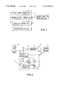
- FIG. 1 is a block diagram showing the conceptual constitution of a camera with a distance measuring apparatus according to the present invention
- FIG. 2 is a block diagram showing the constitution of a camera with a distance measuring apparatus in a first embodiment according to the present invention
- FIGS. 3A through 3F are timing charts for explaining selective control sequences for an active system and a passive system
- FIG. 4 is a block diagram of important parts showing the outline of a camera with a distance measuring apparatus in the second embodiment according to the present invention
- FIGS. 5A and 5B show the luminance patterns of light incident on sensor arrays 32 a and 32 b shown in FIG. 4 and outputs of sensor cells forming the sensor arrays, respectively;
- FIG. 6 is a curve showing FF values
- FIGS. 7A through 7D show the outputs of the sensor arrays 32 a and 32 b in FIG. 4, respectively;
- FIG. 8 shows the principle of an active AF distance measurement
- FIG. 9 shows a state of a reflection signal light spot Sp having a width of b formed on a half-division sensor 32 B;
- FIG. 10 is a circuit diagram showing the connection of the sensor arrays
- FIG. 11 is a circuit diagram for realizing a method of A/D converting the outputs of the respective sensor cells in the censor arrays in a passive AF mode;
- FIG. 12 is an amplifier output waveform view for realizing a method of A/D converting the outputs of the respective sensor cells in the sensor arrays in a passive AF mode;
- FIG. 13 is a flow chart for describing an ordinary control sequence when a camera having two AF systems, i.e., an active system and a passive system according to the conventional technique conducts focusing control;
- FIG. 14 is a flow chart for describing a control sequence for a camera with a distance measuring apparatus in the second embodiment according to the present invention.
- FIG. 15 shows the constitution of an application of the camera with a distance measuring apparatus in the second embodiment according to the present invention
- FIG. 16 is a flow chart for describing the operation of the application of the camera with a distance measuring apparatus in the second embodiment according to the present invention.
- FIG. 17 shows a scene in which an object is not at the center on a plane.
- FIG. 1 is the conceptual view of a camera with a distance measuring apparatus according to the present invention.
- the camera with a distance measuring apparatus of the present invention includes at least a first signal forming unit 1 , a second signal forming unit 2 , a selective control unit 3 , a release detecting unit 4 and an object condition detecting unit 5 .
- the camera with a distance measuring apparatus is formed by connecting those constituent elements as shown in FIG. 1 .
- the first signal forming unit 1 has a light projecting unit and a light receiving unit described later. A distance measuring light is projected from the light projecting unit, a reflection signal of the distance measuring light reflected by an object is received by the light receiving unit and a focusing signal for the object is formed.
- the second signal forming unit 2 has an image signal detecting unit described later.
- the image signal detecting unit monitors a luminance distribution state using light constantly applied onto the object, and forms a focusing signal for the object.
- the release detecting unit 4 detects that a photographer has operated a release operating member described later.
- the object condition detecting unit 5 operates either the first or second signal forming unit 1 or 2 before the operation of the release operating member and detects the condition of the object based on the obtained signal.
- the selective control unit 3 selectively controls the first and second signal forming unit 1 and 2 so as to obtain a focusing signal for the object based on the detection result of the object condition detecting unit 5 when the release detecting unit 4 detects the operation of the release operating member.
- the camera with a distance measuring apparatus of the present invention selects one of the two focusing systems; a passive system and an active system before a release switch as the release operating member is depressed and takes control as if one of the systems is already selected by the time the release is turned on. By so doing, release time lag is removed.
- focusing is effected by the system which has been selected through sufficient judgment without considering processing time at which either of the system should be selected, whereby more accurate focusing can be expected.
- FIG. 2 is a block diagram showing the constitution of a camera with a distance measuring apparatus in the first embodiment according to the present invention.
- This embodiment concerns a case where the present invention is applied to a digital camera for photographing an object using an image pickup device.
- an image of an object 26 is formed on an image pickup device 12 such as a CCD by a photographing lens 11 .
- An image signal from the image pickup device 12 is stored in a memory 13 provided in a later stage in a synchronous manner with timing at which the release switch 15 as the release operating member is turned on.
- a CPU 14 comprising of a one-chip microcomputer and the like, compresses the image signal stored in the memory 13 into a predetermined format and records the resultant signal in a storage medium 17 .
- the CPU 14 also assumes control of the respective elements including a focusing control unit 18 .
- An active type AF unit 25 includes a driver circuit 19 receiving an output from the CPU, an infrared light emitting diode 20 connected to the driver circuit 19 and serving as a light projecting unit, a light projecting lens 21 arranged in front of the infrared light emitting diode 20 , a light receiving lens 22 serving as a light receiving unit forming an image of a reflection light from the object, a light position detecting unit (referred to as ‘PSD’ hereinafter) 23 and an integrated circuit (referred to as ‘AFIC’) 24 .
- PSD light position detecting unit
- AFIC integrated circuit
- the CPU 14 controls the driver circuit 19 at a predetermined timing to project light from the infrared light emitting diode 20 .
- an image of the reflection light from the object 26 is formed on the PDS 23 through the light receiving lens 22 .
- the PSD 23 outputs a current signal dependent on the position of incident signal light.
- the AFIC 24 amplifies the current signal, performs an analog operation, converts the current signal into a signal according to a distance to the object and outputs the resultant signal to the CPU 14 .
- the CPU 14 performs an operation to determine a focusing position based on the signal from the AFIC 24 .
- the incident position of the reflection signal light from the object 26 on the PSD 23 is changed in accordance with the distance to the object.
- the reflection light is incident on a position distant from a light projection system, whereas if the distance to the object 26 is long, the reflection light is incident on a position close to the light projection system.
- the active AF unit 25 functions to determine the distance to the object by means of a tigonometrical survey system.
- a power switch 16 to appropriately switch on the respective elements only when the camera is used.
- a normal electronic camera employs a focusing system in which a contrast is determined while moving the photographing lens 11 to provide the highest contrast of an image signal obtained at the image pickup device 12 to thereby allow the CPU 14 to determine an optimum focusing position.
- a contrast is determined while moving the photographing lens 11 to provide the highest contrast of an image signal obtained at the image pickup device 12 to thereby allow the CPU 14 to determine an optimum focusing position.
- the object has a low contrast or the object is in a dark environment, sufficient accuracy cannot be obtained.
- this embodiment is intended to correctly measure the distance to the object even in the above-described situations by employing the active system AF unit 25 .
- focusing control is conducted with respect to an object in a dark environment or that with a low contrast based on the distance measurement result of the active type AF, thereby increasing the number of targets whose distances can be measured with high accuracy.
- the active type AF is not appropriate for a distant object or a black object. In those cases, use of the contrast system is preferable.
- the active system AF is actuated at certain intervals to thereby allow the CPU 14 to determine rough distance information in advance of a time at which a photographer depresses the release switch 15 .
- the CPU 14 determines whether focusing operation should be conducted by the contrast system or the active system. If the measurement result prior to the operation of the release switch 15 indicates a long distance, the contrast system is used to conduct focusing operation.
- the active system AF is re-executed to thereby conduct focusing operation.
- this embodiment adopts the active type AF to measure a distance prior to the operation of the release switch is that the active system AF is capable of measuring a distance at higher speed than that of the contrast system.
- the contrast system occasionally determines the contrast of the obtained image while moving the lens as stated above. Due to this, the power to move the lens is unnecessarily consumed. From the viewpoint of energy saving, it is advantageous to employ the active AF first.
- the CPU 14 determines which system is appropriate from the distance measurement result obtained in advance. While operating the release switch 15 , focusing control is conducted by means of the selected system, with the result that it is possible to provide a camera with a distance measuring apparatus without causing time loss and without missing shutter timing.
- the present invention is assumed to be applied to a digital camera including an image pickup device used as a photographing system. Needless to say, the present invention is applicable to focusing control for other cameras such as a so-called “silver camera”.
- an optical system dedicated to distance measurement and an image detecting device may be sometimes additionally provided and focusing control is conducted by means of the passive type AF.
- the active AF for radiating infrared is made use of in many cameras.
- a camera with a distance measuring apparatus in a second embodiment according to the present invention is assumed to be applied to an image pickup camera having the above constitution.
- FIG. 4 is a block diagram of important parts showing the schematic constitution of the camera with a distance measuring apparatus in the second embodiment according to the present invention.
- the distance measuring apparatus in this embodiment mainly consists of a CPU 40 serving as control means for assuming control of the overall measuring apparatus, a distance measuring unit 36 for introducing distance measurement light and conducting distance measuring processing, an LED driver 38 and a light emitting diode (LED) 38 a serving as light projecting means and an AFIC 37 serving as a detecting circuit for active AF.
- This apparatus is capable of executing distance measurement both in the first distance measurement mode, i.e., a passive AF mode and in the second distance measuring mode, i.e., an active AF mode.
- a switch denoted by a reference symbol 41 is a release switch corresponding to the release switch 15 in FIG. 3 .
- the switch may be a remote control switch actuated upon receiving a remote control signal from a remote controller which is not shown in FIG. 4 .
- sensor arrays 32 a and 32 b for passive AF incorporated in the distance measuring unit 36 are used.
- each of the sensor cells is converted from an analog to a digital signal by an analog/digital (A/D) converter circuit 34 incorporating therein an integrating circuit serving as the integrating means. Thereafter, image displacement quantities on the sensor arrays 32 a and 32 b are operated by an operating circuit 35 .
- A/D analog/digital
- the operating circuit 35 operates a distance Z to an object based on the image displacement quantities.
- the LED 38 a serving as light projecting means emits light and projects a pulse-like signal light toward the object 49 .
- the reflection light is introduced to one sensor array 32 b of the two sensor arrays 32 a and 32 b.
- the outputs of the sensor cells in the sensor array 32 b are separated from the A/D converter circuit 34 incorporating the integrating circuit by the switching circuit 33 incorporated in the distance measuring unit 36 .
- the outputs are inputted into the active AFIC 37 as a combined output.
- the AFIC 37 obtains a distance to the object based on the information on the image of the object by means of the trigonometric survey system.
- a focusing lens is fed to the object focusing position by a focusing drive control unit which is not shown.
- two light receiving lenses 31 a and 31 b are arranged spaced apart from each other by a base length B1 or parallax and two sensor arrays 32 a and 32 b are arranged at a focal length f to the lenses.
- a distance Z to object is obtained based on the luminance pattern image shifted quantities of the object 49 on the sensor arrays 32 a and 32 b due to the parallax.
- the object light is incident on the sensor arrays 32 a and 32 b through the light receiving lenses 31 a and 31 b.
- the outputs of the sensor arrays 32 a and 32 b are introduced into the A/D converter circuit 34 in units of sensor cell through the switching circuit 33 . After being integrated, the outputs are converted from analog to digital signals.
- the operating circuit 35 operates the object distance Z based on the digital information from the A/D converter circuit 34 .
- pulse-like light emitted from the light emitting diode (LED) 38 serving as light projecting means is converged onto the light projecting lens 39 and then projected onto the object 49 .
- the reflection light from the object 49 is incident on the sensor array 32 b through one of the light receiving lenses 31 b.
- the output of the sensor array 32 b is inputted into the active AFIC 37 serving as the detecting circuit in such a way that outputs of the respective cells are combined.
- the outputs of the sensor array 32 b are halved at the central portion of the array in the switching circuit 33 and outputted as combined output.
- the AFIC 37 comprises of a steady light removing circuit 37 a and a signal processing circuit 37 b.
- a well-known steady light removing circuit 37 a functions to remove light other than the signal light constantly incident on the sensor array 32 b , that is, photocurrent based on background light is removed, whereby only the pulse-like photocurrent components based on the signal light are subjected to processing by the signal processing circuit 37 b.
- the switching circuit 33 can switch over the sensor arrays to individually deal with the output signals of the sensor arrays and to deal with the respective outputs by adding them.
- the output line of the sensor array 321 is not connected to the AFIC 37 if the mode is switched to the active AF mode and it functions only in the passive AF mode.
- the relative positional difference x of the distribution of light incident on the sensor arrays 32 a and 32 b is changed depending on the object distance Z because of the base length B1 which is a distance by which the light receiving lenses 31 a and 31 b are spaced apart.
- the object distance Z is obtained as:
- the sensor cells of the sensor arrays 32 a and 32 b then output current signals in accordance with the quantity of incident light.
- the outputs of the current signals are converted to digital signals by the A/D converter circuit 34 including the integrating circuit serving as integrating means for integrating the current signals.
- the relative positional difference x can be obtained if the image shift quantity operating circuit 35 performs a correlation operation base on the distal signals.
- the result is inputted to the CPU 40 comprising a one-chip microcomputer or the like and serving as operation control means.
- the CPU 40 the above expression (1) is operated to thereby obtain the object distance Z.
- the above is an ordinary constitution of the passive system, tigonometrical distance measuring apparatus.
- the shift quantity operating function normally comprises of two processes described later.
- the two processes may be incorporated into the CPU 40 as software processing.
- a photographic focusing lens of the camera is controlled through an actuator such as a motor by the CPU 40 which assumes control of the operation of the camera at the time of adjusting the focus of the camera, it is possible to realize a camera with AF (auto-focus) feature.
- a correlation operation step of examining a shift in units of sensor pitches, i.e., at sensor cell pitches and an interpolation operation step of calculating the shift quantity with higher resolution than that of the former step by interpolation are required as the two processes for operating the image shift quantity on the sensor arrays.
- FIGS. 5A and 5B show the relationship between the sensor cell position indicating the luminance pattern of light incident on the sensor arrays 32 a and 32 b and the outputs of the sensor cells forming the sensor arrays.
- the sensor array 32 a which is a right (R) sensor, comprises of sensor cells a 1 to a 6 , where indexes 1 to 6 indicate the absolute position of a sensor cell ai based on the optical axis of the light receiving lens 32 a.
- the sensor array 32 b which is a left (L) sensor, comprises of sensor cells b 1 to b 6 as in the case of the sensor array 32 a , where indexes 1 to 6 indicate the absolute position of a sensor cell b 1 based on the optical axis of the light receiving lens 32 a.
- the sensor cell pitch is set at Ps.
- a difference added value FF obtained by subtracting an output L of a sensor cell from an output R of a corresponding sensor cell and absolute values added for the respective sensor cells may be used.
- the sensor cell output L(i) is subtracted from the sensor cell output R(i) while the sensor cells correspond to each other and the absolute value of the difference is obtained.
- the difference added value FF(i) is obtained.
- the difference added value FF(i+1) can be represented by the following expression:
- the outputs of the right and left sensor arrays 32 a and 32 b are balanced at a shift quantity Sf at which the difference added value FF obtained by adding the differences between outputs R and L has a minimum Fmin.
- the shift quantity Sf at this time becomes the sensor cell shift quantity S.
- FIGS. 5A and 5B are the output distributions of both the sensor arrays 32 a and 32 b which are diagrammatically shown in view of the above sensor cell shift quantity S. That is, a luminance pattern of the output R of the index-added sensor cell ai in the sensor array 32 a without shift, as shown in FIG. 5A, and a luminance pattern of the output L of the index-added sensor cell bi+S in the sensor array 32 b which is shifted by the shift quantity S as shown in FIG. 5B are obtained.
- the image shift quantities on the two sensor arrays 32 a and 32 b are not shifted according to the sensor cell pitch.
- This process is referred to as an ‘interpolation operation’ which will be described based on FIGS. 7A through 7D showing outputs of the respective sensor arrays.
- FIGS. 7A through 7D denote outputs of part of sensor cells in the sensor arrays 32 a and 32 b shown in FIG. 4, respectively.
- FIGS. 7A through 7D are arranged for the sake of comparison, while indicating a state in which the above-stated correlation operation is finished and in which the outputs are shifted by the above shift quantity S.
- the outputs L0 to L4 in FIGS. 7A through 7D should be actually described as LS to LS+4 which are outputs shifted by S.
- the shift quantity S is not shown therein to avoid making drawing appear.
- FIG. 8 shows the principle of active AF distance measurement. Description will be given with a half-division sensor 32 B instead of the sensor array 32 b used in the constitution of the distance measuring apparatus in this embodiment.
- the LED 38 a emits pulse-like distance measurement light toward the object 49 through the light projecting lens 39 .
- the output of the distance measurement reflection signal light, reflected by the object 49 , is incident on the half-division sensor 32 B through the light receiving lens 31 b . Since the reflection signal light is pulse-like light opposed to the background light constantly incident on the sensor, the signal light is separated by the AFIC 37 using frequency difference and timing.
- FIG. 9 shows the state of a reflection signal light spot Sp having a width of b which image is formed on the half-division sensor 32 B.
- the center of the spot Sp enters a position xp which satisfies the following relationship:
- ipa ip ⁇ (Xp+b/2 ⁇ a)/b
- ipb ip ⁇ ( ⁇ Xp+b/2+a)/b (7)
- a is a distance from the reference K to a division point Cp on the halved sensor array 32 b.
- Symbol ip is total signal photocurrent. If the photocurrents ipa and ipb are added, the ip is obtained.
- the above-mentioned sensor array 32 b is applied as the half-division sensor 32 B in the distance measuring apparatus in FIG. 8 .
- the apparatus in this embodiment is the same as that of FIG. 8 in constitution except for the sensor array 32 b and the switching circuit 33 for switching the output of the array 32 b.
- the distance measuring apparatus comprises the LED 38 a and the light projecting lens 39 , which serve as the light projecting means, for applying pulse-like distance measurement light toward the object 49 , the light receiving lens 31 b introducing the reflection signal light of the object 49 , the AFIC 37 separating the reflection signal light as pulse signal light and performing distance measuring operation and the like.
- the outputs of the respective cells in the sensor array 32 b are halved at the half-division point Cp, combined by the switching circuit 3 and outputted to the AFIC 37 as photocurrents ipa and ipb.
- the apparatus in FIG. 10 can exhibit the same advantage as that of FIG. 8 .
- the switching operation of the switching circuit 33 allows the outputs of the sensor array 32 b used for the distance measurement in the passive AF mode to be changed to a combined output state as shown in FIG. 10 in the active AF mode and photocurrents ipa and ipb to be outputted.
- the distance can be measured in the passive AF mode and the active AF mode using the same cell array by switching operation.
- FIG. 11 is a circuit diagram showing details of a sensor cell 32 b i which is a light receiving device forming the sensor array 32 b shown in FIG. 4, the switching circuit 33 switching the output of the sensor cell 32 b i and the integrating circuit.
- the light receiving sensor cell 32 b i of the sensor array 32 outputs a photocurrent according to the intensity of the incident light.
- switch-over switches SW 1 and SW 2 of the switching circuit 33 are turned off and on, respectively by a switch (SW) control circuit 40 a incorporated in the CPU 40 , the photocurrents are integrated and converted into voltages by the function of an integrating amplifier 41 and an integrating capacitor 42 which use the first reference voltage Vref 1 as a reference voltage.
- SW switch
- the outputs are inputted to a comparator 43 and compared with a second reference voltage Vref 2 .
- the switch-over switch SW 3 is turned on by the switch control circuit 40 a and then turned off, the output control circuit 40 a and then turned off, the output of the integrating amplifier 41 is first fixed to the reference voltage Vref 1 .
- the integrated voltage is changed depending on the magnitude of photocurrent, i.e., on light intensity.
- a comparator 43 determines time TINT required until the integrated voltage reaches the reference voltage Vref 2 .
- the time TINT is shorter. If smaller, integrating operation is slower and the time TINT is longer.
- the intensity of light incident on the respective sensor cells 32 b i can be obtained digitally and a signal indicating an object condition can be obtained.
- the switch-over switch SW 2 is turned off and the SW 1 is turned on.
- the terminals 44 are bound together as shown in the circuit diagram of FIG. 10 and connected to the AFIC 37 having the above-stated functions, thereby making it possible to detect reflection signal light when the LED emits distance measuring light.
- FIG. 14 is a flow chart showing a control sequence in the second embodiment according to the present invention.
- This control sequence is characterized in that not only display but also the following distance measuring sequence steps are carried out before the release switch (or remote control switch) 41 is depressed.
- step S 23 it is determined how long it will take to conduct integrating control from the luminance of the object, characters of the image and the like (in step S 23 ) and then integrating control is carried out (in step S 24 ).
- a limiter is set such that integrating operation is finished after a predetermined time even if the operation is not sufficient yet, to move to the next step (in steps S 25 , S 26 ).
- the image signal thus obtained is always monitored by the CPU 40 (in step S 27 ).
- step S 28 a display step is executed (in step S 28 ).
- step S 21 if the release switch 41 is depressed (in step S 21 ) and the distance is already measured (in step S 22 ), then it is detected whether or not the image signal obtained has a contrast (in step S 29 ). If the image signal has a contrast, the distance to the object is calculated using the image signal which has been previously obtained and focusing control is carried out (in steps S 30 , S 33 ). Thereafter, exposure control is carried out (in step S 34 ).
- the photographer naturally wants to monitor the image signal in a real-time manner before the operation of the release switch 41 . Due to this, the distance calculation is characteristically made at a timing after the operation of the release switch 41 for the purpose of shortening the processing time as much as possible.
- step S 29 if the image signal obtained does not have a contrast (in step S 29 ), the distance measurement by the passive AF is inappropriate and the operation of the active AF is executed (in steps S 31 , S 32 ). Thereafter, focusing control and exposure control are conducted (in steps S 33 , S 34 ).
- the second embodiment it is possible to realize highly accurate AF without undesired objects by taking good advantage of the active AF and the passive AF and, therefore, to provide a camera with a distance measurement apparatus with less release time lag.
- the background is, for example, a night piece
- integrating operation is limited by the light of the background while detecting an image by means of the passive AF.
- an image of an object a man
- the man's image is blurred.
- a plurality of light projecting devices 51 are connected to a selective driver 52 controlled by the CPU 57 .
- a light projecting lens 50 is provided on the optical axis of the light emitted by the light projecting device 51 .
- light receiving lenses 53 and 54 for forming an image of reflection light and a sensor array 55 in the back of the lenses.
- the output of the sensor array 55 is connected to the input of the CPU 57 through the A/D converter 56 .
- a plurality of light projecting devices 51 are required.
- the devices 51 are selected in accordance with the detected low contrast point and the selected device emits light.
- the low contrast point is detected in advance by a passive sensor during the distance measurement conducted prior to the release operation, which is a characteristic feature of the present invention (in steps S 51 , S 53 , S 54 ).
- a low contrast point is detected by the CPU 52 from the image obtained by the passive sensor (in steps S 51 to S 54 ).
- the detected point is applied with light after release operation and the distance to the detected point is measured based on the principle of the active AF (in step S 56 ).
- the shortest distance is selected, for example, and focusing and exposure controls are conducted (in steps S 58 to 60 ).
- a suited and most effective distance measuring method is selected to thereby allow high-speed focusing.
- the present invention includes two systems different in focusing operation to thereby eliminate objects difficult to deal with and determines which system to be adopted before release operation.
- the present invention can provide a camera with a distance measurement apparatus having a quick response.
- the present invention since the present invention has distance measuring functions by means of both the active and passive AF systems, it is possible to measure distances to objects in a wide variety of conditions. As a result, it is possible to solve the problem of missing shutter timing due to release time lag and further to provide a camera with a distance measuring apparatus which can realize a small-size, high-speed camera system.
Landscapes
- Physics & Mathematics (AREA)
- General Physics & Mathematics (AREA)
- Optics & Photonics (AREA)
- Automatic Focus Adjustment (AREA)
- Focusing (AREA)
- Measurement Of Optical Distance (AREA)
Abstract
Description


Claims (23)
Applications Claiming Priority (2)
| Application Number | Priority Date | Filing Date | Title |
|---|---|---|---|
| JP20043098A JP4002680B2 (en) | 1998-07-15 | 1998-07-15 | Camera with distance measuring device |
| JP10-200430 | 1998-07-15 |
Publications (1)
| Publication Number | Publication Date |
|---|---|
| US6222996B1 true US6222996B1 (en) | 2001-04-24 |
Family
ID=16424177
Family Applications (1)
| Application Number | Title | Priority Date | Filing Date |
|---|---|---|---|
| US09/349,221 Expired - Lifetime US6222996B1 (en) | 1998-07-15 | 1999-07-07 | Camera with distance measuring apparatus for preferentially controlling passive and active type AF system |
Country Status (2)
| Country | Link |
|---|---|
| US (1) | US6222996B1 (en) |
| JP (1) | JP4002680B2 (en) |
Cited By (12)
| Publication number | Priority date | Publication date | Assignee | Title |
|---|---|---|---|---|
| US6377753B1 (en) * | 1999-07-14 | 2002-04-23 | Olympus Optical Co., Ltd. | Multiple-point automatic focusing camera |
| US6385402B1 (en) * | 1999-06-01 | 2002-05-07 | Olympus Optical Co., Ltd. | Distance measuring apparatus |
| US6438324B1 (en) * | 1999-05-20 | 2002-08-20 | Olympus Optical Co., Ltd. | Multi-autofocus distance-measuring system with a wide distance-measuring area |
| US6442345B1 (en) * | 1999-05-20 | 2002-08-27 | Olympus Optical Co., Ltd. | Distance-measuring device and distance-measuring method |
| US6522394B2 (en) * | 2000-08-23 | 2003-02-18 | Canon Kabushiki Kaisha | Rangefinder device and camera |
| US6636699B2 (en) * | 2000-07-12 | 2003-10-21 | Canon Kabushiki Kaisha | Focus detection device and distance measurement device |
| US20060018650A1 (en) * | 2004-07-21 | 2006-01-26 | Canon Kabushiki Kaisha | Image pickup apparatus and defocus amount correction value calculation method |
| US20070086768A1 (en) * | 2005-10-19 | 2007-04-19 | Premier Image Technology Corporation | Method and image capture device for autofocus via specific light signal |
| US20080024649A1 (en) * | 2006-07-25 | 2008-01-31 | Canon Kabushiki Kaisha | Imaging apparatus |
| US20170176714A1 (en) * | 2015-12-18 | 2017-06-22 | Asml Netherlands B.V. | Focus Monitoring Arrangement and Inspection Apparatus Including Such an Arrangement |
| CN112335227A (en) * | 2019-08-21 | 2021-02-05 | 深圳市大疆创新科技有限公司 | Control device, imaging system, control method, and program |
| US11284779B2 (en) * | 2018-06-26 | 2022-03-29 | Olympus Corporation | Endoscope |
Families Citing this family (2)
| Publication number | Priority date | Publication date | Assignee | Title |
|---|---|---|---|---|
| JP6321145B2 (en) * | 2014-05-02 | 2018-05-09 | 富士フイルム株式会社 | Ranging device, ranging method, and ranging program |
| JP2016142676A (en) * | 2015-02-04 | 2016-08-08 | ソニー株式会社 | Information processing device, information processing method, program and imaging device |
Citations (11)
| Publication number | Priority date | Publication date | Assignee | Title |
|---|---|---|---|---|
| US4255029A (en) * | 1978-09-04 | 1981-03-10 | Karl Vockenhuber | Focusing device |
| JPS60105270A (en) | 1983-11-11 | 1985-06-10 | Canon Inc | Method of controlling differential type sensor |
| US4697904A (en) * | 1984-11-28 | 1987-10-06 | Canon Kabushiki Kaisha | Automatic focusing system |
| US4980716A (en) * | 1988-04-28 | 1990-12-25 | Canon Kabushiki Kaisha | Focus detecting device |
| US5315342A (en) * | 1992-12-28 | 1994-05-24 | Eastman Kodak Company | Automatic focus and indirect illumination camera system |
| US5652926A (en) | 1993-12-15 | 1997-07-29 | Fuji Photo Optical Co., Ltd. | Distance measuring apparatus |
| US5655160A (en) * | 1995-06-09 | 1997-08-05 | Fuji Photo Optical Co., Ltd. | Distance measuring apparatus |
| US5848301A (en) * | 1997-02-10 | 1998-12-08 | Olympus Optical Co., Ltd. | Camera and range finder |
| US5870178A (en) * | 1996-02-20 | 1999-02-09 | Canon Kabushiki Kaisha | Distance measuring apparatus |
| US5915233A (en) | 1996-06-04 | 1999-06-22 | Olympus Optical Co., Ltd. | Distance measuring apparatus |
| US5963308A (en) * | 1996-02-20 | 1999-10-05 | Canon Kabushiki Kaisha | Distance measuring apparatus |
-
1998
- 1998-07-15 JP JP20043098A patent/JP4002680B2/en not_active Expired - Fee Related
-
1999
- 1999-07-07 US US09/349,221 patent/US6222996B1/en not_active Expired - Lifetime
Patent Citations (11)
| Publication number | Priority date | Publication date | Assignee | Title |
|---|---|---|---|---|
| US4255029A (en) * | 1978-09-04 | 1981-03-10 | Karl Vockenhuber | Focusing device |
| JPS60105270A (en) | 1983-11-11 | 1985-06-10 | Canon Inc | Method of controlling differential type sensor |
| US4697904A (en) * | 1984-11-28 | 1987-10-06 | Canon Kabushiki Kaisha | Automatic focusing system |
| US4980716A (en) * | 1988-04-28 | 1990-12-25 | Canon Kabushiki Kaisha | Focus detecting device |
| US5315342A (en) * | 1992-12-28 | 1994-05-24 | Eastman Kodak Company | Automatic focus and indirect illumination camera system |
| US5652926A (en) | 1993-12-15 | 1997-07-29 | Fuji Photo Optical Co., Ltd. | Distance measuring apparatus |
| US5655160A (en) * | 1995-06-09 | 1997-08-05 | Fuji Photo Optical Co., Ltd. | Distance measuring apparatus |
| US5870178A (en) * | 1996-02-20 | 1999-02-09 | Canon Kabushiki Kaisha | Distance measuring apparatus |
| US5963308A (en) * | 1996-02-20 | 1999-10-05 | Canon Kabushiki Kaisha | Distance measuring apparatus |
| US5915233A (en) | 1996-06-04 | 1999-06-22 | Olympus Optical Co., Ltd. | Distance measuring apparatus |
| US5848301A (en) * | 1997-02-10 | 1998-12-08 | Olympus Optical Co., Ltd. | Camera and range finder |
Cited By (17)
| Publication number | Priority date | Publication date | Assignee | Title |
|---|---|---|---|---|
| US6438324B1 (en) * | 1999-05-20 | 2002-08-20 | Olympus Optical Co., Ltd. | Multi-autofocus distance-measuring system with a wide distance-measuring area |
| US6442345B1 (en) * | 1999-05-20 | 2002-08-27 | Olympus Optical Co., Ltd. | Distance-measuring device and distance-measuring method |
| US6385402B1 (en) * | 1999-06-01 | 2002-05-07 | Olympus Optical Co., Ltd. | Distance measuring apparatus |
| US6377753B1 (en) * | 1999-07-14 | 2002-04-23 | Olympus Optical Co., Ltd. | Multiple-point automatic focusing camera |
| US6636699B2 (en) * | 2000-07-12 | 2003-10-21 | Canon Kabushiki Kaisha | Focus detection device and distance measurement device |
| US6522394B2 (en) * | 2000-08-23 | 2003-02-18 | Canon Kabushiki Kaisha | Rangefinder device and camera |
| US7412159B2 (en) * | 2004-07-21 | 2008-08-12 | Canon Kabushiki Kaisha | Image pickup apparatus and defocus amount correction value calculation method |
| US20060018650A1 (en) * | 2004-07-21 | 2006-01-26 | Canon Kabushiki Kaisha | Image pickup apparatus and defocus amount correction value calculation method |
| US20070086768A1 (en) * | 2005-10-19 | 2007-04-19 | Premier Image Technology Corporation | Method and image capture device for autofocus via specific light signal |
| US20080024649A1 (en) * | 2006-07-25 | 2008-01-31 | Canon Kabushiki Kaisha | Imaging apparatus |
| US7834929B2 (en) * | 2006-07-25 | 2010-11-16 | Canon Kabushiki Kaisha | Imaging apparatus |
| US20110013073A1 (en) * | 2006-07-25 | 2011-01-20 | Canon Kabushiki Kaisha | Imaging apparatus |
| US8451369B2 (en) * | 2006-07-25 | 2013-05-28 | Canon Kabushiki Kaisha | Imaging apparatus |
| US20170176714A1 (en) * | 2015-12-18 | 2017-06-22 | Asml Netherlands B.V. | Focus Monitoring Arrangement and Inspection Apparatus Including Such an Arrangement |
| US10215954B2 (en) * | 2015-12-18 | 2019-02-26 | Asml Netherlands B.V. | Focus monitoring arrangement and inspection apparatus including such an arrangement |
| US11284779B2 (en) * | 2018-06-26 | 2022-03-29 | Olympus Corporation | Endoscope |
| CN112335227A (en) * | 2019-08-21 | 2021-02-05 | 深圳市大疆创新科技有限公司 | Control device, imaging system, control method, and program |
Also Published As
| Publication number | Publication date |
|---|---|
| JP2000028902A (en) | 2000-01-28 |
| JP4002680B2 (en) | 2007-11-07 |
Similar Documents
| Publication | Publication Date | Title |
|---|---|---|
| US6222996B1 (en) | Camera with distance measuring apparatus for preferentially controlling passive and active type AF system | |
| US7405762B2 (en) | Camera having AF function | |
| JP2001004909A (en) | Camera having automatic focusing device | |
| JP3585291B2 (en) | Automatic focusing device | |
| JP2002244027A (en) | Range-finding device | |
| JP3872841B2 (en) | Ranging device | |
| CN100378569C (en) | Distance-measuring device set in camera | |
| JPH10221065A (en) | Distance-measuring device | |
| US7167202B2 (en) | Image pick-up apparatus and distance measuring device | |
| US6501910B2 (en) | Camera distance measuring device | |
| US6350976B1 (en) | Distance measuring apparatus | |
| US6826362B2 (en) | Camera having distance measuring apparatus | |
| JP2001305422A (en) | Range finder | |
| US6195509B1 (en) | Exposure control apparatus for a camera | |
| JP5171124B2 (en) | Focus adjustment device, imaging device, and focus adjustment method | |
| US6556785B2 (en) | Range finder | |
| JP2000180703A (en) | Range finder | |
| JP3423109B2 (en) | Focus detection device having variable amount of auxiliary light | |
| JPH1183474A (en) | Distance measuring device | |
| US6470149B1 (en) | Distance measuring apparatus | |
| JP2005148229A (en) | Photoelectric convertor and automatic focus detector | |
| US6597867B2 (en) | Distance measuring apparatus | |
| JP2000121352A (en) | Range finder | |
| JP2511919B2 (en) | Automatic focus detection device | |
| JPH0961704A (en) | Range-finding system and autofocusing camera |
Legal Events
| Date | Code | Title | Description |
|---|---|---|---|
| AS | Assignment |
Owner name: OLYMPUS OPTICAL CO., LTD., JAPAN Free format text: ASSIGNMENT OF ASSIGNORS INTEREST;ASSIGNOR:NONAKA, OSAMU;REEL/FRAME:010089/0386 Effective date: 19990702 |
|
| FEPP | Fee payment procedure |
Free format text: PAYOR NUMBER ASSIGNED (ORIGINAL EVENT CODE: ASPN); ENTITY STATUS OF PATENT OWNER: LARGE ENTITY |
|
| STCF | Information on status: patent grant |
Free format text: PATENTED CASE |
|
| FEPP | Fee payment procedure |
Free format text: PAYOR NUMBER ASSIGNED (ORIGINAL EVENT CODE: ASPN); ENTITY STATUS OF PATENT OWNER: LARGE ENTITY Free format text: PAYER NUMBER DE-ASSIGNED (ORIGINAL EVENT CODE: RMPN); ENTITY STATUS OF PATENT OWNER: LARGE ENTITY |
|
| FPAY | Fee payment |
Year of fee payment: 4 |
|
| FPAY | Fee payment |
Year of fee payment: 8 |
|
| FPAY | Fee payment |
Year of fee payment: 12 |
|
| AS | Assignment |
Owner name: OLYMPUS CORPORATION, JAPAN Free format text: CHANGE OF ADDRESS;ASSIGNOR:OLYMPUS CORPORATION;REEL/FRAME:039344/0502 Effective date: 20160401 |